WO2011036964A1 - 使い捨ての体液吸収性着用物品 - Google Patents
使い捨ての体液吸収性着用物品 Download PDFInfo
- Publication number
- WO2011036964A1 WO2011036964A1 PCT/JP2010/063764 JP2010063764W WO2011036964A1 WO 2011036964 A1 WO2011036964 A1 WO 2011036964A1 JP 2010063764 W JP2010063764 W JP 2010063764W WO 2011036964 A1 WO2011036964 A1 WO 2011036964A1
- Authority
- WO
- WIPO (PCT)
- Prior art keywords
- top sheet
- width direction
- sheet
- wearing article
- core material
- Prior art date
Links
Images


Classifications
-
- A—HUMAN NECESSITIES
- A61—MEDICAL OR VETERINARY SCIENCE; HYGIENE
- A61F—FILTERS IMPLANTABLE INTO BLOOD VESSELS; PROSTHESES; DEVICES PROVIDING PATENCY TO, OR PREVENTING COLLAPSING OF, TUBULAR STRUCTURES OF THE BODY, e.g. STENTS; ORTHOPAEDIC, NURSING OR CONTRACEPTIVE DEVICES; FOMENTATION; TREATMENT OR PROTECTION OF EYES OR EARS; BANDAGES, DRESSINGS OR ABSORBENT PADS; FIRST-AID KITS
- A61F13/00—Bandages or dressings; Absorbent pads
- A61F13/15—Absorbent pads, e.g. sanitary towels, swabs or tampons for external or internal application to the body; Supporting or fastening means therefor; Tampon applicators
- A61F13/45—Absorbent pads, e.g. sanitary towels, swabs or tampons for external or internal application to the body; Supporting or fastening means therefor; Tampon applicators characterised by the shape
- A61F13/47—Sanitary towels, incontinence pads or napkins
- A61F13/475—Sanitary towels, incontinence pads or napkins characterised by edge leakage prevention means
- A61F13/4751—Sanitary towels, incontinence pads or napkins characterised by edge leakage prevention means the means preventing fluid flow in a transversal direction
- A61F13/4752—Sanitary towels, incontinence pads or napkins characterised by edge leakage prevention means the means preventing fluid flow in a transversal direction the means being an upstanding barrier
- A61F13/4753—Sanitary towels, incontinence pads or napkins characterised by edge leakage prevention means the means preventing fluid flow in a transversal direction the means being an upstanding barrier the barrier being not integral with the topsheet or backsheet
-
- A—HUMAN NECESSITIES
- A61—MEDICAL OR VETERINARY SCIENCE; HYGIENE
- A61F—FILTERS IMPLANTABLE INTO BLOOD VESSELS; PROSTHESES; DEVICES PROVIDING PATENCY TO, OR PREVENTING COLLAPSING OF, TUBULAR STRUCTURES OF THE BODY, e.g. STENTS; ORTHOPAEDIC, NURSING OR CONTRACEPTIVE DEVICES; FOMENTATION; TREATMENT OR PROTECTION OF EYES OR EARS; BANDAGES, DRESSINGS OR ABSORBENT PADS; FIRST-AID KITS
- A61F13/00—Bandages or dressings; Absorbent pads
- A61F13/15—Absorbent pads, e.g. sanitary towels, swabs or tampons for external or internal application to the body; Supporting or fastening means therefor; Tampon applicators
- A61F13/45—Absorbent pads, e.g. sanitary towels, swabs or tampons for external or internal application to the body; Supporting or fastening means therefor; Tampon applicators characterised by the shape
- A61F13/49—Absorbent articles specially adapted to be worn around the waist, e.g. diapers
- A61F13/494—Absorbent articles specially adapted to be worn around the waist, e.g. diapers characterised by edge leakage prevention means
- A61F13/49406—Absorbent articles specially adapted to be worn around the waist, e.g. diapers characterised by edge leakage prevention means the edge leakage prevention means being at the crotch region
- A61F13/49413—Absorbent articles specially adapted to be worn around the waist, e.g. diapers characterised by edge leakage prevention means the edge leakage prevention means being at the crotch region the edge leakage prevention means being an upstanding barrier
- A61F13/4942—Absorbent articles specially adapted to be worn around the waist, e.g. diapers characterised by edge leakage prevention means the edge leakage prevention means being at the crotch region the edge leakage prevention means being an upstanding barrier the barrier not being integral with the top- or back-sheet
-
- A—HUMAN NECESSITIES
- A61—MEDICAL OR VETERINARY SCIENCE; HYGIENE
- A61F—FILTERS IMPLANTABLE INTO BLOOD VESSELS; PROSTHESES; DEVICES PROVIDING PATENCY TO, OR PREVENTING COLLAPSING OF, TUBULAR STRUCTURES OF THE BODY, e.g. STENTS; ORTHOPAEDIC, NURSING OR CONTRACEPTIVE DEVICES; FOMENTATION; TREATMENT OR PROTECTION OF EYES OR EARS; BANDAGES, DRESSINGS OR ABSORBENT PADS; FIRST-AID KITS
- A61F13/00—Bandages or dressings; Absorbent pads
- A61F13/15—Absorbent pads, e.g. sanitary towels, swabs or tampons for external or internal application to the body; Supporting or fastening means therefor; Tampon applicators
- A61F13/51—Absorbent pads, e.g. sanitary towels, swabs or tampons for external or internal application to the body; Supporting or fastening means therefor; Tampon applicators characterised by the outer layers
- A61F13/511—Topsheet, i.e. the permeable cover or layer facing the skin
- A61F13/51104—Topsheet, i.e. the permeable cover or layer facing the skin the top sheet having a three-dimensional cross-section, e.g. corrugations, embossments, recesses or projections
Definitions
- This invention relates to disposable body fluid absorbent wearing articles such as disposable diapers and sanitary napkins.
- Disposable body fluid-absorbing wearing articles such as disposable diapers and sanitary napkins in which a body fluid-absorbing core material is interposed between a liquid-permeable top sheet and a liquid-impermeable back sheet are well known.
- the top sheet it is formed so that the peak part and trough part which are parallel to each other and extend in one direction and are alternately arranged in a direction orthogonal to the one direction face the skin of the diaper wearer. Things are known.
- JP-A-58-132155 discloses a liquid-permeable nonwoven fabric suitable for use as a surface material for disposable diapers and sanitary napkins.
- This nonwoven fabric has a concavo-convex pattern consisting of convex portions and concave portions extending in parallel to each other in the machine direction in the manufacturing process of the nonwoven fabric, and the density is low in the portion corresponding to the convex portion and the density in the portion corresponding to the concave portion. It is expensive.
- Patent Document 2 JP 2008-25079 A (Patent Document 2) also discloses a liquid-permeable nonwoven fabric suitable for use as a surface material for disposable diapers and sanitary napkins.
- this nonwoven fabric one of the two surfaces is formed substantially flat, and the other surface is formed with a convex portion and a concave portion extending in parallel to each other in the machine direction.
- the portions and the concave portions are alternately arranged in the crossing direction orthogonal to the machine direction.
- the convex portion has a higher density than the concave portion.
- Patent Document 3 also discloses a liquid-permeable nonwoven fabric suitable for use as a top sheet of disposable diapers and sanitary napkins.
- this nonwoven fabric one of the two surfaces is formed substantially flat, and the other surface is formed with ridges and valleys extending in parallel to each other in the machine direction. Are arranged alternately in the crossing direction perpendicular to the machine direction.
- the raised portion includes fibers oriented in the thickness direction of the nonwoven fabric.
- a breakwater is provided on both sides of the article.
- the body fluid-absorbing core material may be sandwiched between the liquid-permeable top sheet and the liquid-impermeable back sheet.
- the non-woven fabric disclosed in any one of Patent Documents 1 to 3 is used as the top sheet, compared with the case where a non-woven fabric having flat surfaces is used as the top sheet, the wearer wears the skin between the wear article and the top sheet. It is possible to create a large air-permeable gap and reduce the contact area between the skin and the top sheet.
- the base edge portion of the breakwater formed of the strip-shaped sheet piece is joined to the top sheet and is to be fixed, it is joined to the convex portion or the raised portion of the nonwoven fabric forming the top sheet. Even if it is easy, it is not always easy to join the base edge to the recess or valley of the nonwoven fabric. As a result, the base edge portion may have to have a larger size in the width direction than when the base edge portion is bonded to the flat surface of the nonwoven fabric.
- the present invention improves the conventional disposable body fluid-absorbing wearing article so that the leak-proof wall can be easily attached to the top sheet having the crest and trough extending in parallel with each other. It is a problem.
- the present invention is intended to have a front-rear direction that matches the front-rear direction of the wearer's body and a width direction orthogonal to the front-rear direction, and a central region in the width direction Including a body fluid-absorbing core material interposed between a liquid-permeable top sheet and a liquid-impermeable back sheet, wherein the top sheet is formed of short fibers of a thermoplastic synthetic resin, A crest and a trough are formed on the outer surface opposite to the inner surface facing the core material, extending in parallel with each other in the front-rear direction and repeating undulations in the width direction, and in the width direction of the core material Disposable body fluid-absorbing wearing articles in which leakage barriers that can elastically extend and contract in the front-rear direction and can stand up from the top sheet are formed on both outer sides.
- the present invention is characterized in that the top sheet is located at a side portion that extends to the outside of the core material over at least a part of the side edge of the core material in the width direction.
- the peak portion is in a compressed state so that the height of the portion is lowered.
- the top sheet is in a compressed state so that a part of the central portion inside the side portion is also lowered in the width direction. .
- the leakage barrier is formed by a strip-shaped sheet piece extending in the front-rear direction, and one of both side edges extending in parallel with each other in the front-rear direction.
- the top sheet is overlapped and joined to the side portion of the top sheet, and the side portion is compressed at the portion where one of both side edge portions of the leakage breaker is overlapped and joined.
- the top sheet includes, in the width direction, a portion where one of both side edges of the leakage breaker is overlapped and joined to the side edge of the core member. The crests are in the compressed state between.
- the worn article is a sanitary napkin.
- the worn article is a disposable diaper, a crotch region extending in the front-rear direction, a front waistline region located in front of the crotch region, and the crotch region A rear waistline region located rearward, and the core material is included in at least the crotch region among these regions.
- the top sheet is joined to the back sheet by overlapping a side portion that extends outward in the width direction beyond the side edge portion of the core member, In the dike, the one of the side edges of the strip-shaped sheet piece is overlapped and joined to the back sheet outside the side portion of the top sheet in the width direction.
- the ridge includes the short fibers oriented in the height direction of the ridge.
- the disposable body fluid absorbent wearing article according to the present invention is formed so that peaks and valleys are alternately arranged on the outer surface of the top sheet, the top sheet is a body fluid absorbent core material.
- the peak part is compressed so that the thickness of the top sheet is reduced.
- a side part becomes flat and it becomes easy to join the base edge part of a breakwater to a side part.
- the partial fracture top view of a diaper The figure which shows the II-II line
- wire cut surface of FIG. The partial broken top view of the sheet piece which forms a top sheet.
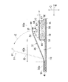
- FIG. 1 is a partially broken plan view of an open-type disposable diaper 1 which is an example of a wearing article according to the present invention.
- the diaper 1 has a longitudinal direction A and a width direction B orthogonal to each other, a rectangular chassis 2 formed to be long in the longitudinal direction A, and attached to a front portion of the chassis 2 and extending in the width direction B.
- a pair of front wings 3 and a pair of rear wings 4 attached to the rear portion of the chassis 2 and extending in the width direction B are included.
- a crotch region 6 is formed between the front wing 3 and the rear wing 4.
- a front waistline region 7 is formed in front of the crotch region 6.
- a rear waistline region 8 is formed.
- the chassis 2 includes a liquid-permeable top sheet 11, a liquid-impermeable back sheet 12, and a body fluid-absorbing core material 13 interposed between the two sheets 11 and 12, and the back sheet 12 is a non-woven fabric with a good touch.
- the outer sheet 14 is made of a metal.
- the top sheet 11 and the back sheet 12 extend from the peripheral edge portion 51 of the core member 13 and overlap each other, and are joined via a hot melt adhesive (not shown).
- the top sheet 11 and the back sheet 12 in the illustrated example have the same size in the front-rear direction A, but the back sheet 12 extends from the side edge 16 of the top sheet 11 in the width direction B.
- the outer sheet 14 having the same dimension in the front-rear direction A as that of the back sheet 12 extends from the side edge 17 of the back sheet 12 in the width direction B.
- the top sheet 11, the back sheet 12, and the outer sheet 14 form both side edge portions 18 and front and rear end edge portions 21 and 22 of the chassis 2 at portions extending from the core member 13.
- Each of the side edge portions 18 is formed with a breakwater 31 by a sheet piece that is long in the front-rear direction A.
- the breakwater 31 is bonded to the side edge 18 via the hot melt adhesive 32a and to the front edge 21 via the hot melt adhesive 32b.
- the top sheet 11 is located inside the chassis 2 with respect to the front edge 34, the rear edge 36 joined to the rear edge 22 via the hot melt adhesive 32c, and the base 33.
- a free edge portion 37 which overlaps with the elastic member 39 in a stretched state via a hot melt adhesive (not shown) inside a sleeve 38 formed on the free edge portion 37. ing.
- leg elastic members 41 extending in the front-rear direction A are located between the outer sheet 14 and the base edge 33 of the leakage breaker 31, and a hot melt adhesive (not shown). It is attached to the outer sheet 14 via
- a front waistline elastic member 42 extending in the width direction B is provided between the top sheet 11 and the back sheet 12, and a hot melt adhesive is applied to at least one of these sheets 11, 12. (Not shown).
- a rear waistline elastic member 43 extending in the width direction B is located between the top sheet 11 and the back sheet 12, and hot melt bonding is performed on at least one of the sheets 11 and 12. It joins via the agent (not shown).
- the chassis 2 thus formed has a front wing 3 attached to a side edge 18 in the front waist area 7 so as to extend in the width direction B, and a side edge in the rear waist area 8.
- a rear wing 4 is attached to 18 so as to extend in the width direction B.
- a tape fastener 46 is attached to the rear wing 4. When the diaper 1 is worn, the tape fastener 46 extends in the width direction B as indicated by the phantom line, and uses the adhesive 47 applied to the inner surface of the tape fastener 46 to apply the outer surface or front of the chassis 2. It can be fixed to the outer surface of the wing 3 in a peelable manner.
- the diaper 1 having such a chassis 2 is symmetrical with respect to the center line L that bisects the width of the chassis 2.
- the leakage breaker 31 The elastic member 39 contracts and the free edge 37 of the leakage breaker 31 moves so as to be separated from the top sheet 11 above the top sheet 11, and the leakage breaker 31 is moved to the top sheet 11 as shown in FIG. Stand up from.
- the standing leakage barrier 31 acts to prevent body fluid flowing in the width direction B over the top sheet 11 in the crotch region 6 from leaking from the diaper 1.
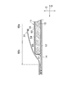
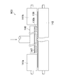
- FIG. 2 is an enlarged view of the section taken along the line II-II in FIG. 1, and the thickness direction of the diaper 1 is indicated by a double-headed arrow C.
- the core material 13 is included in at least the center region in the width direction B in the crotch region 6 of the diaper 1, and the water absorbent material 52 such as pulverized pulp or highly water absorbent polymer particles is removed from the tissue.
- the upper surface 54 is covered with the top sheet 11 and the lower surface 56 is covered with the back sheet 12.
- seat 12 with which the base edge part 33 of the leak-proof wall 31 opposes it It joins with the outer sheet
- the state when the free edge portion 37 of the breakwater 31 and the intermediate portion 35 between the free edge portion 37 and the base edge portion 33 stand up from the top sheet 11 is indicated by virtual lines.
- the top sheet 11 has an inner surface 57 facing the core member 13 and an outer surface 58 opposite to the inner surface 57, and the inner surface 57 is formed almost smoothly.
- the outer surface 58 is formed such that peaks 61 and valleys 62 are alternately arranged in the width direction B in the central portion 60 a that is inside the peripheral edge 51 in the crotch region 6 of the core member 13, and extends from the peripheral edge 51.
- the side part 60b which is the outer part that protrudes, is flat except for the part in contact with the peripheral part 51, and its thickness t is smaller than the height H of the peak 61 in the central part 60a. Is formed.
- the base edge portion 33 of the leakage breaker 31 is joined to the side portion 60 b formed flat with respect to the top sheet 11.
- the central portion 60a of the top sheet 11 can easily come into contact with the skin of the diaper wearer at the mountain portion 61, while the valley portion 62 can easily come into contact with the skin. Without this, an air passage extending in the front-rear direction A can be formed between the skin and the top sheet 11 at the valley 62.
- a boundary portion 65 between the central portion 60a and the side portion 60b in the top sheet 11 of FIG. 2 is indicated by an imaginary line in FIG.
- FIG. 3 is a view showing a section taken along line III-III in FIG.
- the shape of the core member 13 in FIG. 1 is such that the portion hidden in the top sheet 11 is indicated by a chain line, is formed in a well-known hourglass shape, has the smallest width in the crotch region 6, The width is wide in the vicinity of the waist area 7 and the rear waist area 8.
- the line III-III extends so as to cross the core member 13 at the portion where the width is increased.
- the boundary portion 65 between the central portion 60a and the side portion 60b in the top sheet 11 extends straight in the front-rear direction A in parallel with the center line L (see FIG. 1).
- FIG. 1 The shape of the core member 13 in FIG. 1 is such that the portion hidden in the top sheet 11 is indicated by a chain line, is formed in a well-known hourglass shape, has the smallest width in the crotch region 6, The width is wide in the vicinity of the waist area 7 and the rear waist area 8.
- the line III-III extend
- the peripheral portion 51 is located closer to the outer side in the width direction B, and the boundary portion 65 and the peripheral portion 51 are separated from each other.
- the flat side portion 60 b of the top sheet 11 is at least a part of the peripheral edge 51 extending in the front-rear direction A of the core member 13, more specifically, of the peripheral edge 51.
- the core material 13 is formed outside the portion where the width is the narrowest.
- FIG. 4 is a partially broken perspective view of a sheet piece 111 used as the top sheet 11.
- the sheet piece 111 is a non-woven fabric formed of a thermoplastic synthetic resin and entangled and welded with hydrophilic short fibers 112 having a fineness of 1 to 8 dtex, and has an upper surface 158 and a lower surface 157. , the basis weight is the mass per unit area in the range of 10 ⁇ 60g / m 2.
- the short fibers 112 may have a fiber length of 5 to 80 mm, and all have substantially the same length, or may have a mixture of different lengths.
- the short fibers 112 may also be straight or crimped by mechanical or thermal treatment.
- thermoplastic synthetic resin forming the short fibers 112 polyethylene, polypropylene, nylon, polyester, or the like can be used.
- the short fibers 112 also include core-sheath type and side-by-side type composite fibers made by using at least two kinds of these thermoplastic synthetic resins.
- a undulating portion 113 is formed at the center portion in the first direction X, and flat portions 114 are formed on both sides of the undulating portion 113.
- peaks 161 and valleys 162 alternately arranged in the first direction X are formed at a pitch of 2 to 7 mm.
- peak portions 161 and valley portions 162 extend in parallel to each other in a second direction Y corresponding to the front-rear direction A of the diaper 1.
- the dimension H between the upper surface 158 and the lower surface 157 of the peak 161 in the third direction Z orthogonal to the first direction X and the second direction Y is the height of the peak 161.
- the dimension H is sometimes referred to as the thickness of the sheet piece 111 in the undulating portion 113
- the third direction Z is sometimes referred to as the thickness direction of the sheet piece 111.
- the dimension between the upper surface 158 and the lower surface 157 in the valley portion 162 is f (see FIG. 2).
- the flat portion 114 has the same basis weight as that of the undulating portion 113, and the dimension between the upper surface 158 and the lower surface 157 is t (see FIG. 2).
- the upper surface 158 and the lower surface 157 of the sheet piece 111 become the outer surface 58 and the inner surface 57 of the top sheet 11.
- the undulating portion 113 and the flat portion 114 of the sheet piece 111 become the central portion 60 a and the side portion 60 b of the top sheet 11, and the peak portion 161 and the valley portion 162 become the peak portion 61 and the valley portion 62.
- the dimension H is in the range of 0.6 to 2 mm
- the dimension f is in the range of 0.4 to 0.6 mm
- the dimension t is in the range of 0.2 to 0.7 mm.
- the measuring method of these dimensions H, f, t is as follows. That is, the dimension H is set such that a pressure plate having a surface pressure of 3 gf / cm 2 with respect to the sheet piece 111 is placed on a plurality of peaks 161 arranged in the first direction X, and a dial gauge contact is placed on the pressure plate. Measure by applying and subtract the thickness of the pressure plate from the measured value.
- the dimension t is obtained by placing a pressure plate on the flat part 114 and using a dial gauge.
- the dimension f is obtained as follows. That is, the sheet knife 111 is cut in the first direction X using a cutter knife replacement blade HA-100 manufactured by KOKUYO, and a cut surface parallel to the first direction X is created. The cut surface is observed with a digital microscope VHX-900 manufactured by Keyence Co., Ltd., and a 25 ⁇ photograph of the cut surface is taken. From the photograph, the separation dimension in the third direction Z between the short fibers forming the upper surface 158 and the short fibers forming the lower surface 157 in the valley 162 is obtained, and the separation dimension is defined as a dimension f.
- the back sheet 12 in the chassis 2 is formed by a film of a thermoplastic synthetic resin such as polyethylene having a thickness of 0.01 to 0.05 mm, and the outer sheet 14 is 10 to 40 g / m 2. It is formed with nonwoven fabrics, such as a spunbon nonwoven fabric, a melt bond nonwoven fabric, and a spunlace nonwoven fabric, having a basis weight of.
- nonwoven fabrics such as a spunbon nonwoven fabric, a melt bond nonwoven fabric, and a spunlace nonwoven fabric, having a basis weight of.
- a liquid-impervious, more preferably liquid-impervious nonwoven fabric or a thermoplastic synthetic resin film is used for the breakwater 31 .
- a laminate of a nonwoven fabric or a nonwoven fabric and a thermoplastic synthetic resin film is used for the front wing 3 and the rear wing 4.
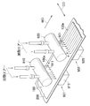
- FIG. 5 and 6 are diagrams showing a part of a process for manufacturing the first nonwoven fabric 130a for obtaining the sheet piece 111 of FIG. 4 from the card web 100, and a continuous body 131 of the sheet piece 111 from the first nonwoven fabric 130a.
- FIG. 5 is a diagram showing a part of a process for obtaining, and the process of FIG. 5 is known by Japanese Patent Laying-Open No. 2009-030218 (Patent Document 3).
- a card web 100 having a basis weight of 10 to 60 g / m 2 formed of short fibers 112 is placed on a running belt 200 that is air permeable in the thickness direction, which is a support base, and moves in the machine direction MD. Run.
- a running belt 200 for example, a mesh plate having an opening of 30 mesh or more is used.
- the first step is a pretreatment step for stabilizing the formation of the card web 100 by welding the short fibers 112 (see FIG. 3) while compressing the card web 100 in the thickness direction.
- curd web 100a which passed the 1st process 901 are provided.
- the first jet air 911 heated from the first nozzle portion 910 is blown against the card web 100.
- the first jet air 911 passes through the card web 100 and the belt 200 and is sucked into the first suction box 912.
- the air volume of the first jet air 911 is approximately the same as or slightly larger than the intake air amount per unit time of the first suction box 912 so that such preliminary processing is possible. Is set.
- the temperature of the first jet air 911 is set to a temperature at which the short fibers 112 can be welded together.
- a plurality of nozzles are arranged in the intersecting direction CD at the center distance a with respect to the pretreatment card web 100a that has passed the first step 901.
- a plurality of heated second jet air 921 is sprayed to obtain the first nonwoven fabric 130a.
- the second jet air 921 partially moves the short fibers 112 in the pretreated card web 100a with stable formation obtained in the first step 901 in the cross direction CD, and the second jet air 921 It is preferable that the air volume of the second nozzle part 920 for that purpose is set to be larger than the air intake quantity of the second suction box 925.
- the position in the cross direction CD of the second jet air 921 sprayed with a center distance a in the second step 902 coincides with the position of the valley 162 in the nonwoven fabric 1 of FIG.
- a part of the short fibers 112 located immediately below the second jet air 921 moves so as to be equally distributed to both sides of the cross direction CD and participates in the formation of the peak portion 161.
- a heat treatment chamber can be provided in the second step 902 on the downstream side of the second nozzle portion 920.
- the first nonwoven fabric 130a is heated to such an extent that the surface of the short fibers 112 is slightly melted, thereby increasing the number of welded portions of the short fibers 112 in the first nonwoven fabric 130a.
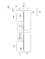
- the second nonwoven fabric 130 b cut out from the first nonwoven fabric 130 a and having a required dimension (width) in the cross direction CD is heated and pressurized with the press roll 140.
- the press roll 140 includes an upper roll 141 and a lower roll 142 that rotate in the machine direction MD.
- the upper roll 141 has an enlarged diameter portion 143 at both ends in the cross direction CD, and the enlarged diameter portion 143 is heated to a required temperature.
- the lower roll 142 supports the second nonwoven fabric 130b from below in the figure.
- the enlarged diameter portion 143 and the lower roll 142 of the upper roll 141 can cooperate to compress both side portions 136 in the cross direction CD of the second nonwoven fabric 130b under heating.
- the lower roll 142 can be used in a state heated to a required temperature, or can be used in a non-heated state.
- the clearance S between the enlarged diameter portion 143 and the lower roll 142 is adjusted so that both side portions 136 of the second nonwoven fabric 130b can be compressed to a required thickness.
- the peripheral speeds of the enlarged diameter portion 143 and the lower roll 142 are also adjusted so that the compression time required to compress the side portions 136 to the required thickness is obtained.
- the second non-woven fabric 130b is compressed under heating using the enlarged diameter portion 143 set to a temperature 3 to 20 ° C. lower than the melting temperature of the thermoplastic synthetic resin forming the short fibers 112, and thereafter By rapidly cooling to room temperature, the compressed and deformed short fibers 112 are maintained in a deformed state, and the side portion 136 has a thickness t (see FIG. 2) with the peaks 161 disappearing. It can be changed to a thin flat portion 114 (see FIG. 3).
- the second nonwoven fabric 130b having the side portion 136 thus changed is a continuum of the sheet piece 111, and is cut so that the dimension in the machine direction MD becomes a required value. It can be set as the sheet piece 111 as the top sheet 11.
- the sheet piece 111 depends on the properties of the card web 100, the operating conditions of the first and second steps 901 and 902 in FIG. Tends to be higher than the density in the other.
- the short fibers 112 tend to be oriented in the height direction at the peaks 161. Further, the valley portion 162 tends to have a large fiber gap because the number of the short fibers 112 per unit area in the sheet piece 111 is small.
- a blower for cooling both side portions 136 of the continuous body 131 can be provided on the downstream side of the roll 140. Further, a roll similar to the roll 140 can be added downstream of the roll 140 in order to make the heating / pressurization time for the both side portions 136 sufficiently long.
- the upper surface 158 of the flat portion 114 has the undulation portion 113. Since it is in a state closer to a plane than the upper surface 158, the bonding of the base edge portion 33 of the leakage breaker 31 to the top sheet 11 by the hot melt adhesive 32 a is more bonded to the flat portion 114 than to the undulating portion 113. It is easy to secure a large mutual bonding area, and as a result, the bonding state of the base edge portion 33 to the top sheet 11 becomes durable.
- the short fibers 112 that have been oriented in the height direction at the peak portion 161 of the second nonwoven fabric 130b are When the mountain portion 161 is compressed and changes to the flat portion 114, the short fibers 112 that tend to stand up in the third direction Z, which is the thickness direction, spread in a plane, in other words, the first direction. It changes so that it may sleep toward X or the 2nd direction Y. Therefore, in the top sheet 11 of the diaper 1 of FIGS. 1 and 2 formed with the sheet piece 111, body fluid flows from the center portion in the width direction B of the chassis 2 to the side edge portion 18 in the crotch region 6.
- the body fluid When the body fluid flows from the central part 60a to the side part 60b in the top sheet 11, the body fluid is quickly dense in the front and rear direction A and the width direction B in the side part 60b in which the short fibers 112 are lying. It becomes possible to diffuse. Since the side edge portion 18 is a portion having a low water absorption capability in which the core material 13 is not interposed between the top sheet 11 and the back sheet 12, body fluid that has flowed in the width direction B in the crotch region 6 is removed from the top sheet. 11 can be diffused at the side portion 60b of the eleventh side, the body fluid does not stay at the side edge portion 18 of the crotch region 6 or less stays, thereby preventing leakage of body fluid in the crotch region 6. be able to.
- the peak portion 161 and the valley portion 162 of the sheet piece 111 in other words, the peak portion 61 and the valley portion 62 of the top sheet 11 are oriented in the height direction of the short fibers 112 in the peak portion 61, and in the valley portion 62. Due to the large gap formed between the short fibers 112, the body fluid in the crotch region 6 easily passes through the top sheet 11, but diffuses in the front-rear direction A and the width direction B at the peak portion 61 and the valley portion 62. Since the ridges 61 and the valleys 62 form the side edge 18 in the crotch region 6 of the chassis 2, the urine stays in the crotch region 6. It is not preferable.
- the side portion 60 b which is a flat portion of the top sheet 11 is in a state in which a part thereof enters between the back sheet 12 and the base edge portion 33 of the breakwater 31.
- FIG. 7 is a diagram illustrating another example of the third step 903 that can be employed instead of the third step 903 in FIG. 6.
- the upper roll 141 of the rolls 140 has a first upper roll 141a and a second upper roll 141b whose rotation axes are opposed to each other in the cross direction CD, and these are heated to a required temperature.
- Each of the first and second upper rolls 141a and 141b cooperates with the lower roll 142, which is heated as necessary, to compress both side parts 136 of the second nonwoven fabric 130b under heating.
- a hot air blowing section 146 is provided between the first upper roll 141a and the second upper roll 141b.
- the hot air blowing section 146 has a plurality of nozzles 147 arranged at a required pitch in the intersecting direction CD, and hot air heated to a required temperature is ejected from the nozzle 147.
- the second nonwoven fabric 130b supplied to the third step 903 in FIG. 7 is formed by passing the web 100 through the first and second steps 901 and 902 in FIG. After exiting, it may be wound up in a roll and stored in units of weeks or months in the state of being wound.
- the second nonwoven fabric 130b stored as such may be deformed to a shape that is close to flat due to the crest 161 being compressed due to being wound up.
- the third step 903 in FIG. 7 is a step that can be adopted when the sheet piece 111 is obtained from the second nonwoven fabric 130b that has been wound up in this way, and is a ridge that is deformed to be crushed.
- the shape of 161 is restored by heating to form the undulating portion 113 required as the sheet piece 111, while compressing the both side portions 136 of the second nonwoven fabric 130 b without compressing or, if necessary, compressing with heating.
- the flat portion 114 of the sheet piece 111 can be formed.
- the lower roll 142 can be replaced with an endless belt (not shown) that travels in the machine direction MD (see FIG. 5).
- the endless belt may be a breathable mesh type belt that allows hot air that has been jetted downward from the nozzle 147 installed above and passed through the nonwoven fabric 136b to travel further downward.
- a non-breathable stainless steel belt or cloth belt that can reflect the hot air toward the nonwoven fabric 130b can be used. Below the breathable belt, suction against the hot air can be applied.
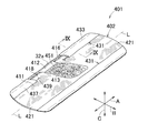
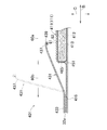
- FIGS. 8 and 9 are a partially broken perspective view of a sanitary napkin 401 which is an example of a disposable body fluid absorbent wearing article according to the present invention, and a cross-sectional view taken along the line IX-IX in FIG.
- the sanitary napkin 401 has a longitudinal direction A, a width direction B, and a thickness direction C that are orthogonal to each other, and is formed long in the longitudinal direction A.
- the sanitary napkin 401 also has a chassis 402 formed by a liquid-permeable top sheet 411, a liquid-impermeable back sheet 412, and a body fluid-absorbing core material 413 interposed between the sheets 411 and 412.
- a leakage breakwater 431 is formed in each of the side edge portions 418 that extend in parallel with each other in the front-rear direction A in the chassis 402.
- the top sheet 411 and the back sheet 412 overlap each other at a portion extending from the peripheral edge portion 451 of the core member 413, and are joined to each other by bonding with an adhesive or by heating, in addition to both side edges 418, both ends A portion 421 is formed.
- the top sheet 411 is formed by the short fibers 112 illustrated in FIG. 3, and at least the peak portion of the central portion 60 a including the peak portion 61 and the valley portion 62, and the peak portion 61 and the valley portion 62.
- 61 has a side portion 60b in a compressed state and in a relatively flat state.
- a boundary portion 465 between the central portion 60a and the side portion 60b is along a portion of the peripheral edge portion 451 of the core member 413 that extends straight in the front-rear direction A at both side edge portions 418.
- the back sheet 412 is formed of a thermoplastic synthetic resin film, and extends in the width direction B so as to extend from the side edge 416 of the top sheet 411.
- the breakwater 431 includes a base edge portion 433 bonded to the side edge portion 418 of the chassis 402 via the hot melt adhesive 32a, both end portions 436 bonded to both end edge portions 421, and a base edge portion 433. And a free edge portion 437 extending in the front-rear direction A, and an elastic member 439 is attached to the free edge portion 437 in an extended state.
- the base edge portion 433 is bonded to the back sheet 412 via the hot melt adhesive 432 a and is also bonded to the flat side portion 60 b of the top sheet 411.
- the base edge portion 433 in the leakage breakwater 431 has a bonding area compared to the case where the base edge portion 433 is bonded to the top sheet 411 at the side portion 60b and is bonded to the top sheet 411 at the peak portion 61. Easy to widen.
- the side part 60 b acts similarly to the side part 60 b of the top sheet 11 in the diaper 1, and the body fluid that flows in the width direction B of the sanitary napkin 401 is diffused in the front-rear direction A. it can.
- the boundary portion 465 between the central portion 60a and the side portion 60b is outside the peripheral portion 451 and adjacent to the peripheral portion 451, in addition to the aspect overlapping the peripheral portion 451 as shown in the figure. It is possible to carry out the present invention in a manner that is inside the peripheral edge 451 or adjacent to the peripheral edge 451.
Landscapes
- Health & Medical Sciences (AREA)
- Epidemiology (AREA)
- Heart & Thoracic Surgery (AREA)
- Engineering & Computer Science (AREA)
- Biomedical Technology (AREA)
- Vascular Medicine (AREA)
- Life Sciences & Earth Sciences (AREA)
- Animal Behavior & Ethology (AREA)
- General Health & Medical Sciences (AREA)
- Public Health (AREA)
- Veterinary Medicine (AREA)
- Fluid Mechanics (AREA)
- Physics & Mathematics (AREA)
- Absorbent Articles And Supports Therefor (AREA)
- Orthopedics, Nursing, And Contraception (AREA)
Priority Applications (5)
| Application Number | Priority Date | Filing Date | Title |
|---|---|---|---|
| AU2010299269A AU2010299269A1 (en) | 2009-09-28 | 2010-08-13 | Disposable wearing article capable of absorbing bodily fluids |
| EA201290101A EA201290101A1 (ru) | 2009-09-28 | 2010-08-13 | Предмет одежды одноразового использования, абсорбирующий выделения организма |
| US13/496,938 US20120226252A1 (en) | 2009-09-28 | 2010-08-13 | Disposable bodily fluid absorbent wearing article |
| EP10818640.4A EP2484320B1 (en) | 2009-09-28 | 2010-08-13 | Disposable wearing article capable of absorbing bodily fluids |
| CN201080043118.2A CN102573738B (zh) | 2009-09-28 | 2010-08-13 | 一次性体液吸收性穿着物品 |
Applications Claiming Priority (2)
| Application Number | Priority Date | Filing Date | Title |
|---|---|---|---|
| JP2009-223445 | 2009-09-28 | ||
| JP2009223445A JP5328586B2 (ja) | 2009-09-28 | 2009-09-28 | 使い捨ての体液吸収性着用物品 |
Publications (1)
| Publication Number | Publication Date |
|---|---|
| WO2011036964A1 true WO2011036964A1 (ja) | 2011-03-31 |
Family
ID=43795723
Family Applications (1)
| Application Number | Title | Priority Date | Filing Date |
|---|---|---|---|
| PCT/JP2010/063764 WO2011036964A1 (ja) | 2009-09-28 | 2010-08-13 | 使い捨ての体液吸収性着用物品 |
Country Status (7)
| Country | Link |
|---|---|
| US (1) | US20120226252A1 (zh) |
| EP (1) | EP2484320B1 (zh) |
| JP (1) | JP5328586B2 (zh) |
| CN (1) | CN102573738B (zh) |
| AU (1) | AU2010299269A1 (zh) |
| EA (1) | EA201290101A1 (zh) |
| WO (1) | WO2011036964A1 (zh) |
Families Citing this family (15)
| Publication number | Priority date | Publication date | Assignee | Title |
|---|---|---|---|---|
| JP5970228B2 (ja) * | 2012-04-19 | 2016-08-17 | 花王株式会社 | 吸収性物品 |
| JP5956323B2 (ja) | 2012-12-13 | 2016-07-27 | ユニ・チャーム株式会社 | ペット用使い捨ておむつ |
| JP6084451B2 (ja) | 2012-12-13 | 2017-02-22 | ユニ・チャーム株式会社 | ペット用使い捨ておむつ |
| JP6084452B2 (ja) | 2012-12-13 | 2017-02-22 | ユニ・チャーム株式会社 | ペット用使い捨ておむつ |
| JP5755631B2 (ja) | 2012-12-13 | 2015-07-29 | ユニ・チャーム株式会社 | ペット用使い捨ておむつ |
| JP6084453B2 (ja) | 2012-12-13 | 2017-02-22 | ユニ・チャーム株式会社 | ペット用使い捨ておむつ |
| JP5755630B2 (ja) | 2012-12-13 | 2015-07-29 | ユニ・チャーム株式会社 | ペット用使い捨ておむつ |
| JP5829599B2 (ja) | 2012-12-13 | 2015-12-09 | ユニ・チャーム株式会社 | ペット用使い捨ておむつ |
| JP5829600B2 (ja) | 2012-12-13 | 2015-12-09 | ユニ・チャーム株式会社 | ペット用使い捨ておむつ |
| JP6084450B2 (ja) | 2012-12-13 | 2017-02-22 | ユニ・チャーム株式会社 | ペット用使い捨ておむつ |
| JP6008729B2 (ja) | 2012-12-13 | 2016-10-19 | ユニ・チャーム株式会社 | ペット用使い捨ておむつ |
| JP6290538B2 (ja) * | 2013-02-07 | 2018-03-07 | ユニ・チャーム株式会社 | 使い捨てのおむつ |
| JP5800876B2 (ja) * | 2013-09-30 | 2015-10-28 | ユニ・チャーム株式会社 | 吸収性物品 |
| JP6175529B1 (ja) * | 2016-03-02 | 2017-08-02 | ユニ・チャーム株式会社 | パンツ型使い捨ておむつ |
| KR102536792B1 (ko) * | 2021-09-10 | 2023-05-26 | 주식회사 디알컴퍼니 | 접밴드부 누수 방지 기능을 갖는 요실금 팬티용 패드 |
Citations (7)
| Publication number | Priority date | Publication date | Assignee | Title |
|---|---|---|---|---|
| JPS58132155A (ja) | 1982-01-31 | 1983-08-06 | ユニ・チヤ−ム株式会社 | 模様を有する不織布の製造方法 |
| JPH05269168A (ja) * | 1992-03-26 | 1993-10-19 | Kobayashi Pharmaceut Co Ltd | 体液吸収用当て材 |
| JP2002524664A (ja) * | 1998-09-03 | 2002-08-06 | ザ、プロクター、エンド、ギャンブル、カンパニー | 強靭で柔かい穿孔不織ウェブ |
| JP2008025079A (ja) | 2006-06-23 | 2008-02-07 | Uni Charm Corp | 不織布 |
| JP2009030218A (ja) | 2007-06-22 | 2009-02-12 | Uni Charm Corp | 不織布およびその製造方法 |
| JP2009118921A (ja) * | 2007-11-12 | 2009-06-04 | Kao Corp | 吸収性物品 |
| JP2009118920A (ja) * | 2007-11-12 | 2009-06-04 | Kao Corp | 吸収性物品の表面シート |
Family Cites Families (11)
| Publication number | Priority date | Publication date | Assignee | Title |
|---|---|---|---|---|
| JPH07299093A (ja) * | 1994-05-10 | 1995-11-14 | Uni Charm Corp | 体液吸収性着用物品 |
| DE4422956A1 (de) * | 1994-06-30 | 1996-01-04 | Schickedanz Ver Papierwerk | Absorbierender Hygieneartikel zur Aufnahme von Körperflüssigkeiten |
| JP3490291B2 (ja) * | 1998-05-18 | 2004-01-26 | ユニ・チャーム株式会社 | 吸収性物品 |
| CN1240125A (zh) * | 1998-06-03 | 2000-01-05 | 尤妮佳股份有限公司 | 具有体液吸收性的物品 |
| JPH11342154A (ja) * | 1998-06-03 | 1999-12-14 | Uni Charm Corp | 体液吸収性物品 |
| JP2000135239A (ja) * | 1998-10-30 | 2000-05-16 | Uni Charm Corp | 使い捨ての体液吸収性着用物品 |
| JP3639450B2 (ja) * | 1999-01-20 | 2005-04-20 | ユニ・チャーム株式会社 | 使い捨ての体液処理用吸収性物品 |
| JP3926587B2 (ja) * | 2001-07-12 | 2007-06-06 | ユニ・チャーム株式会社 | 吸収性物品 |
| US7132585B2 (en) * | 2002-12-05 | 2006-11-07 | Uni-Charm Corporation | Absorbent article with liquid acquisition layer |
| JP4738049B2 (ja) * | 2005-05-02 | 2011-08-03 | ユニ・チャーム株式会社 | 吸収性物品 |
| JP5054963B2 (ja) * | 2006-11-27 | 2012-10-24 | ユニ・チャーム株式会社 | 吸収性物品 |
-
2009
- 2009-09-28 JP JP2009223445A patent/JP5328586B2/ja not_active Expired - Fee Related
-
2010
- 2010-08-13 EA EA201290101A patent/EA201290101A1/ru unknown
- 2010-08-13 US US13/496,938 patent/US20120226252A1/en not_active Abandoned
- 2010-08-13 WO PCT/JP2010/063764 patent/WO2011036964A1/ja active Application Filing
- 2010-08-13 AU AU2010299269A patent/AU2010299269A1/en not_active Abandoned
- 2010-08-13 EP EP10818640.4A patent/EP2484320B1/en not_active Not-in-force
- 2010-08-13 CN CN201080043118.2A patent/CN102573738B/zh active Active
Patent Citations (7)
| Publication number | Priority date | Publication date | Assignee | Title |
|---|---|---|---|---|
| JPS58132155A (ja) | 1982-01-31 | 1983-08-06 | ユニ・チヤ−ム株式会社 | 模様を有する不織布の製造方法 |
| JPH05269168A (ja) * | 1992-03-26 | 1993-10-19 | Kobayashi Pharmaceut Co Ltd | 体液吸収用当て材 |
| JP2002524664A (ja) * | 1998-09-03 | 2002-08-06 | ザ、プロクター、エンド、ギャンブル、カンパニー | 強靭で柔かい穿孔不織ウェブ |
| JP2008025079A (ja) | 2006-06-23 | 2008-02-07 | Uni Charm Corp | 不織布 |
| JP2009030218A (ja) | 2007-06-22 | 2009-02-12 | Uni Charm Corp | 不織布およびその製造方法 |
| JP2009118921A (ja) * | 2007-11-12 | 2009-06-04 | Kao Corp | 吸収性物品 |
| JP2009118920A (ja) * | 2007-11-12 | 2009-06-04 | Kao Corp | 吸収性物品の表面シート |
Non-Patent Citations (1)
| Title |
|---|
| See also references of EP2484320A4 |
Also Published As
| Publication number | Publication date |
|---|---|
| JP5328586B2 (ja) | 2013-10-30 |
| AU2010299269A1 (en) | 2012-05-03 |
| EP2484320B1 (en) | 2014-11-05 |
| CN102573738B (zh) | 2015-04-15 |
| EP2484320A1 (en) | 2012-08-08 |
| EP2484320A4 (en) | 2013-09-18 |
| JP2011067563A (ja) | 2011-04-07 |
| CN102573738A (zh) | 2012-07-11 |
| US20120226252A1 (en) | 2012-09-06 |
| EA201290101A1 (ru) | 2012-11-30 |
Similar Documents
| Publication | Publication Date | Title |
|---|---|---|
| JP5328586B2 (ja) | 使い捨ての体液吸収性着用物品 | |
| TWI544908B (zh) | Preparation method of liquid permeable sheet | |
| JP5939773B2 (ja) | 使い捨て着用物品の吸収層 | |
| JP5309022B2 (ja) | シート状部材の積層体 | |
| TWI519280B (zh) | Disposable disposable diaper | |
| RU2404057C2 (ru) | Шов, соединяющий вместе, по меньшей мере, два рулонных материала | |
| JP3949020B2 (ja) | 吸収性物品 | |
| WO2010055699A1 (ja) | 使い捨ての体液吸収性着用物品 | |
| JP5832761B2 (ja) | 吸収性着用物品 | |
| CA2312624C (en) | Composite plastic sheet and process for making the same | |
| JP6355808B2 (ja) | 吸収性物品 | |
| JP6004723B2 (ja) | 使い捨ておむつ | |
| KR101615415B1 (ko) | 일회용 팬츠형 착용 물품 | |
| JP5818738B2 (ja) | 透液性シート | |
| CN109640913B (zh) | 吸收性物品及用于其的立体开孔片的制造方法 | |
| KR101164697B1 (ko) | 음순간 패드 | |
| JP6029734B2 (ja) | 使い捨て着用物品の吸収層の製造方法 | |
| CN108348376B (zh) | 吸收性物品 | |
| WO2012053945A1 (en) | Method for applying elastic elements to a disposable article and disposable article produced according to the method | |
| EP4321140A1 (en) | Method and apparatus for the manufacture of absorbent article with transversal barrier | |
| JP7478038B2 (ja) | 吸収性物品 | |
| JP6467391B2 (ja) | 吸収性物品 | |
| US20240041663A1 (en) | Method and apparatus for manufacturing an elastic laminate and a disposable absorbent hygiene product comprising the elastic laminate | |
| JP5577906B2 (ja) | 吸収性物品用シートの製造方法、吸収性物品用シート及び吸収性物品 | |
| WO2018088164A1 (ja) | 吸収性物品 |
Legal Events
| Date | Code | Title | Description |
|---|---|---|---|
| WWE | Wipo information: entry into national phase |
Ref document number: 201080043118.2 Country of ref document: CN |
|
| 121 | Ep: the epo has been informed by wipo that ep was designated in this application |
Ref document number: 10818640 Country of ref document: EP Kind code of ref document: A1 |
|
| WWE | Wipo information: entry into national phase |
Ref document number: 2179/CHENP/2012 Country of ref document: IN |
|
| WWE | Wipo information: entry into national phase |
Ref document number: 2010818640 Country of ref document: EP |
|
| WWE | Wipo information: entry into national phase |
Ref document number: 201290101 Country of ref document: EA |
|
| NENP | Non-entry into the national phase |
Ref country code: DE |
|
| WWE | Wipo information: entry into national phase |
Ref document number: 1201001395 Country of ref document: TH |
|
| WWE | Wipo information: entry into national phase |
Ref document number: 2010299269 Country of ref document: AU |
|
| ENP | Entry into the national phase |
Ref document number: 2010299269 Country of ref document: AU Date of ref document: 20100813 Kind code of ref document: A |
|
| WWE | Wipo information: entry into national phase |
Ref document number: 13496938 Country of ref document: US |