EP2484320B1 - Disposable wearing article capable of absorbing bodily fluids - Google Patents
Disposable wearing article capable of absorbing bodily fluids Download PDFInfo
- Publication number
- EP2484320B1 EP2484320B1 EP10818640.4A EP10818640A EP2484320B1 EP 2484320 B1 EP2484320 B1 EP 2484320B1 EP 10818640 A EP10818640 A EP 10818640A EP 2484320 B1 EP2484320 B1 EP 2484320B1
- Authority
- EP
- European Patent Office
- Prior art keywords
- topsheet
- side edges
- ridges
- width direction
- core material
- Prior art date
- Legal status (The legal status is an assumption and is not a legal conclusion. Google has not performed a legal analysis and makes no representation as to the accuracy of the status listed.)
- Not-in-force
Links
Images


Classifications
-
- A—HUMAN NECESSITIES
- A61—MEDICAL OR VETERINARY SCIENCE; HYGIENE
- A61F—FILTERS IMPLANTABLE INTO BLOOD VESSELS; PROSTHESES; DEVICES PROVIDING PATENCY TO, OR PREVENTING COLLAPSING OF, TUBULAR STRUCTURES OF THE BODY, e.g. STENTS; ORTHOPAEDIC, NURSING OR CONTRACEPTIVE DEVICES; FOMENTATION; TREATMENT OR PROTECTION OF EYES OR EARS; BANDAGES, DRESSINGS OR ABSORBENT PADS; FIRST-AID KITS
- A61F13/00—Bandages or dressings; Absorbent pads
- A61F13/15—Absorbent pads, e.g. sanitary towels, swabs or tampons for external or internal application to the body; Supporting or fastening means therefor; Tampon applicators
- A61F13/45—Absorbent pads, e.g. sanitary towels, swabs or tampons for external or internal application to the body; Supporting or fastening means therefor; Tampon applicators characterised by the shape
- A61F13/47—Sanitary towels, incontinence pads or napkins
- A61F13/475—Sanitary towels, incontinence pads or napkins characterised by edge leakage prevention means
- A61F13/4751—Sanitary towels, incontinence pads or napkins characterised by edge leakage prevention means the means preventing fluid flow in a transversal direction
- A61F13/4752—Sanitary towels, incontinence pads or napkins characterised by edge leakage prevention means the means preventing fluid flow in a transversal direction the means being an upstanding barrier
- A61F13/4753—Sanitary towels, incontinence pads or napkins characterised by edge leakage prevention means the means preventing fluid flow in a transversal direction the means being an upstanding barrier the barrier being not integral with the topsheet or backsheet
-
- A—HUMAN NECESSITIES
- A61—MEDICAL OR VETERINARY SCIENCE; HYGIENE
- A61F—FILTERS IMPLANTABLE INTO BLOOD VESSELS; PROSTHESES; DEVICES PROVIDING PATENCY TO, OR PREVENTING COLLAPSING OF, TUBULAR STRUCTURES OF THE BODY, e.g. STENTS; ORTHOPAEDIC, NURSING OR CONTRACEPTIVE DEVICES; FOMENTATION; TREATMENT OR PROTECTION OF EYES OR EARS; BANDAGES, DRESSINGS OR ABSORBENT PADS; FIRST-AID KITS
- A61F13/00—Bandages or dressings; Absorbent pads
- A61F13/15—Absorbent pads, e.g. sanitary towels, swabs or tampons for external or internal application to the body; Supporting or fastening means therefor; Tampon applicators
- A61F13/45—Absorbent pads, e.g. sanitary towels, swabs or tampons for external or internal application to the body; Supporting or fastening means therefor; Tampon applicators characterised by the shape
- A61F13/49—Absorbent articles specially adapted to be worn around the waist, e.g. diapers
- A61F13/494—Absorbent articles specially adapted to be worn around the waist, e.g. diapers characterised by edge leakage prevention means
- A61F13/49406—Absorbent articles specially adapted to be worn around the waist, e.g. diapers characterised by edge leakage prevention means the edge leakage prevention means being at the crotch region
- A61F13/49413—Absorbent articles specially adapted to be worn around the waist, e.g. diapers characterised by edge leakage prevention means the edge leakage prevention means being at the crotch region the edge leakage prevention means being an upstanding barrier
- A61F13/4942—Absorbent articles specially adapted to be worn around the waist, e.g. diapers characterised by edge leakage prevention means the edge leakage prevention means being at the crotch region the edge leakage prevention means being an upstanding barrier the barrier not being integral with the top- or back-sheet
-
- A—HUMAN NECESSITIES
- A61—MEDICAL OR VETERINARY SCIENCE; HYGIENE
- A61F—FILTERS IMPLANTABLE INTO BLOOD VESSELS; PROSTHESES; DEVICES PROVIDING PATENCY TO, OR PREVENTING COLLAPSING OF, TUBULAR STRUCTURES OF THE BODY, e.g. STENTS; ORTHOPAEDIC, NURSING OR CONTRACEPTIVE DEVICES; FOMENTATION; TREATMENT OR PROTECTION OF EYES OR EARS; BANDAGES, DRESSINGS OR ABSORBENT PADS; FIRST-AID KITS
- A61F13/00—Bandages or dressings; Absorbent pads
- A61F13/15—Absorbent pads, e.g. sanitary towels, swabs or tampons for external or internal application to the body; Supporting or fastening means therefor; Tampon applicators
- A61F13/51—Absorbent pads, e.g. sanitary towels, swabs or tampons for external or internal application to the body; Supporting or fastening means therefor; Tampon applicators characterised by the outer layers
- A61F13/511—Topsheet, i.e. the permeable cover or layer facing the skin
- A61F13/51104—Topsheet, i.e. the permeable cover or layer facing the skin the top sheet having a three-dimensional cross-section, e.g. corrugations, embossments, recesses or projections
Definitions
- This invention relates to disposable bodily fluid absorbent wearing articles such as disposable diapers and sanitary napkins.
- disposable bodily fluid absorbent wearing articles such as disposable diapers and sanitary napkins including a core material assembly interposed between a liquid-pervious topsheet and a liquid-impervious backsheet are known. It is also known to form the topsheet with ridges and troughs extending in parallel to each other in one direction and arranged alternately in a direction being orthogonal to the direction so that these ridges and troughs face the wearer's skin.
- JP S58-132155 A discloses a liquid-pervious nonwoven fabric suitable to be used as a surface material of disposable diapers or sanitary napkins.
- This nonwoven fabric has a convexo-concave pattern composed of ridges and troughs extending in parallel to each other in a machine direction in manufacturing process for the nonwoven fabric wherein the fiber density is relatively low in the ridges and relatively high in the troughs.
- JP 2008-25079 A also discloses a liquid-pervious nonwoven fabric suitable to be used as a surface material of disposable diapers or sanitary napkins.
- this nonwoven fabric one of both surfaces is formed to be substantially flat and the other surface is formed with ridges and troughs extending in parallel to each other in the machine direction in such a manner that these ridges and troughs are arranged alternately in a direction orthogonal to the machine direction.
- the ridges have a density higher than that of the troughs.
- JP 2009-030218 A also discloses a liquid-pervious nonwoven fabric suitable to be used as a topsheet of disposable diapers or sanitary napkins.
- this nonwoven fabric also, one of both surfaces is formed to be substantially flat and the other surface is formed with ridges and troughs extending in parallel to each other in the machine direction and are arranged alternately in a direction orthogonal to the machine direction.
- the ridges contain fibers oriented in the thickness direction of the nonwoven fabric.
- the bodily fluid absorbent wearing articles such as disposable diapers and sanitary napkins
- opposite side edges of the article are provided with the leakage-barriers in order to prevent bodily fluids from leaking out beyond these side edges and, between the opposite leakage-barriers, the bodily fluid absorbent core material assembly is sandwiched between the liquid-pervious topsheet and the liquid-impervious backsheet.
- the topsheet disclosed in any one of PTL 1 through 3 it is possible to ensure a sufficient volume of air-permeable clearances between the article wearer's skin and the topsheet and, in contrast with the case in which the topsheet of which both surfaces are flat, correspondingly the contact area between the skin and the topsheet may be reduced.
- An object of the present invention is to improve the conventional disposable bodily fluid absorbent wearing article so that leakage-barriers may be easily attached to the topsheet being formed with the ridges and the troughs extending in parallel to each other.
- This invention provides a disposable bodily fluid absorbent wearing article as recited by Claim 1.
- this invention resides in that the topsheet extends outward in the width direction at least partially beyond opposite side edges of the core material assembly to define lateral regions extending outside the core material assembly and, in these lateral regions, the ridges are in a compressed state to become lower in height.
- the topsheet is in a compressed state also in part of a central region defined inboard of the lateral regions in the width direction to become lower in height than the ridges.
- the wearing article is a sanitary napkin.
- the wearing article is a disposable diaper including a crotch region extending in the front-back direction, a front waist region lying in front of the crotch region and a rear waist region lying behind the crotch region and the core material assembly is contained at least in the crotch region of these regions.
- the lateral regions of the topsheet extending in the width direction beyond the opposite side edges of the core material assembly are overlapped and bonded together with the backsheet and the respective ones of the opposite side edges of the belt-like sheet strips forming the respective leakage-barriers are overlapped and bonded together outside the respective lateral regions of the topsheet as viewed in the width direction.
- the ridges contain the short fibers oriented in a height direction of the ridges.
- the opposite lateral regions of the topsheet extending outward at least partially beyond the opposite side edges of the bodily fluid absorbent core material assembly are in a state such that the ridges have been compressed and the thickness of the topsheet has been reduced.
- the opposite lateral regions are sufficiently flattened to assure that the proximal side edges of the respective leakage-barriers may be easily bonded to the opposite lateral regions of the topsheet.
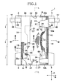
- Fig. 1 is a partially cutaway plan view of an open-type disposable diaper 1 as an example of the wearing article according to this invention.
- the diaper 1 has a front-back direction A and a width direction B being orthogonal to each other, and includes a rectangular chassis 2 shaped to be relatively long in the front-back direction A, a pair of front wings 3 attached to a front section of the chassis 2 so as to extend in the width direction B and a pair of rear wings 4 attached to a rear section of the chassis 2 so as to extend in the width direction B.
- a crotch region 6 is defined between the front wings 3 and the rear wings 4, a front waist region 7 is defined in front side of the crotch region 6 and a rear waist region 8 is defined in rear side of the crotch region 6.
- the chassis 2 includes a liquid-pervious topsheet 11, a liquid-impervious backsheet 12 and a bodily fluid absorbent core material assembly 13 interposed between these two sheets 11, 12 wherein the backsheet 12 is covered with an outer sheet 14 made of a nonwoven fabric having a comfortable texture.
- the topsheet 11 and the backsheet 12 extend outward beyond a peripheral regions 51 of the core material assembly 13 and are overlapped together outside the peripheral regions 51 and bonded to each other with hot melt adhesive (not shown). While the topsheet 11 and the backsheet 12 exemplarily illustrated are dimensioned to be the same in the front-back direction A, in the width direction B, the backsheet 12 extends outward beyond opposite side edges 16 of the topsheet 11.
- While the outer sheet 14 is dimensioned to be the same as the backsheet 12 in the front-back direction A, in the width direction B, the outer sheet 14 extends beyond opposite side edges 17 of the backsheet 12. Respective outer extensions of these topsheet 11, backsheet 12 and outer sheet 14 beyond the core material assembly 13 define opposite side edges 18 and front and rear ends 21, 22 of the chassis 2. Along the opposite side edges 18, paired leakage-barriers 31 are formed of individually cut out sheets which are relatively long in the front-back direction A.
- leakage-barriers 31 respectively include proximal side edges 33 bonded to the side edges 18 with hot melt adhesive 32a, front ends 34 bonded to the front end 21 with hot melt adhesive 32b, rear ends 36 bonded to the rear end 22 with hot melt adhesive 32c, and free side edges 37 lying on the inner side of the chassis 2 compared to the proximal side edges 33 and separably overlapping the topsheet 11 wherein the respective free side edges 37 form sleeves 38 and elastic members 39 are attached under tension to inner sides of the respective sleeves 38 with hot melt adhesives (not shown).
- leg elastic members 41 are disposed between the outer sheet 14 and the proximal side edges 33 of the respective leakage-barriers 31 and attached under tension in the front-back direction A to the outer sheet 14 with hot melt adhesives (not shown).
- front waist elastic members 42 are disposed between the topsheet 11 and the backsheet 12 and bonded under tension in the width direction B to at least one of these sheets 11, 12 with hot melt adhesive (not shown).
- rear waist elastic members 43 are disposed between the topsheet 11 and the backsheet 12 and bonded under tension in the width direction B to at least one of these two sheets 11, 12 with hot melt adhesives (not shown) .
- the chassis 2 formed in the manner as described above is provided on the opposite side edges 18 in the front waist region 7 with the front wings 3 extending outward in the width direction B and on the opposite side edges 18 in the rear waist region 8 with the rear wings 4 extending outward in the width direction B.
- the rear wings 4 respectively have tape fasteners 46 attached thereto.
- the tape fasteners 46 may be extended outward in the width direction B as indicated by imaginary lines and may be releasably fastened to the outer surface of the chassis 2 or to the outer surface of the front winds 3 with pressure-sensitive adhesive 47 applied to the inner surfaces of the respective tape fasteners 46.
- the diaper 1 having such chassis 2 is symmetric about a center line L bisecting the width of the chassis 2 and when the chassis 2 is bowed in the front-back direction A with the topsheet 11 inside to be U-shaped, the free side edges 37 of the leakage-barriers 31 are spaced apart from the topsheet 11 under contraction of the elastic members 39 and the leakage-barriers 31 rise on the topsheet 11 as will be illustrated later in Fig. 2 .
- the leakage-barriers 31 standing up in this manner function to prevent bodily fluids flowing on the topsheet 11 of the crotch region 6 in the width direction B from leaking out of the diaper 1.
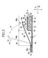
- Fig. 2 is an enlarged sectional view taken along line II-II in Fig. 1 wherein a thickness direction of the diaper 1 is indicated by a double-headed arrow C.
- the core material assembly 13 occupies at least a midsection in the width direction B of the crotch region 6 and including water-absorptive material 52 such as fluff wood pulp and superabsorbent polymer particles wrapped with a wrapping sheet 53 formed of, for example, tissue paper or a liquid-pervious nonwoven fabric which is liquid-pervious, preferably not only liquid-pervious but also liquid-absorptive, and even more preferably, in addition to these two properties, liquid-dispersant.
- water-absorptive material 52 such as fluff wood pulp and superabsorbent polymer particles wrapped with a wrapping sheet 53 formed of, for example, tissue paper or a liquid-pervious nonwoven fabric which is liquid-pervious, preferably not only liquid-pervious but also liquid-absorptive, and even more preferably, in addition to these two properties
- the core material assembly 13 has an upper surface 54 covered with the topsheet 11 and a lower surface 56 covered with the backsheet 12.
- the proximal side edges 33 of the respective leakage-barriers 31 are bonded to the topsheet 11, the backsheet 12 and the outer sheet 14 opposed to the respective proximal side edges 33 with hot melt adhesive 32a.
- the situation in which the free side edges 37 of the respective leakage-barriers 31 and intermediate portions 35 defined between the free side edges 37 and the proximal side edges 33, respectively, are standing up on the topsheet 11 is indicated by imaginary lines.
- the topsheet 11 has an inner surface 57 facing the core material assembly 13 and an outer surface 58 opposite to the inner surface 57 wherein the inner surface 57 is substantially flat.
- a central region 60a of the outer surface 58 defined inboard of peripheral regions 51 of the core material assembly 13 in the crotch region 6 is formed with ridges 61 and troughs 62 alternating in the width direction B and lateral regions 60b of the outer surface 58 extending outward from the peripheral regions 51 are flat except regions in contact with the peripheral regions 51.
- a thickness t of the topsheet 11 in the lateral regions 60b is smaller than a height H of the ridges 61 in the central region 60a.
- the proximal side edges 33 of the respective leakage-barriers 31 are bonded to the topsheet 11 in the flat lateral regions 60b thereof.
- the central region 60a of the topsheet 11 may easily come in contact with the wearer's skin at the respective ridges 61 but not easily come in contact with the wearer's skin at the respective troughs 62 and, in consequence, air passages may be formed between the wearer's skin and the topsheet 11 along the respective troughs 62 extending in the front-back direction A.
- Boundary regions 65 between the central region 60a and the respective lateral regions 60b in Fig. 2 are indicated by imaginary lines.
- Fig. 3 is a sectional view taken along line III-III in Fig. 1 .
- the core material assembly 13 partially hidden behind the topsheet 11 as indicated by dotted line in Fig. 1 has a known hourglass-shape having its width narrowest in the crotch region 6 and gradually enlarged toward the front waist region 7 and the rear waist region 8.
- the line III-III extends across the core material assembly 13 in its region having an enlarged width.
- the boundary regions 65 between the central region 60a and the lateral regions 60b rectilinearly extend in parallel to the center line L (See Fig. 1 ) in the front-back direction A. In Fig. 2 , these boundary regions 65 lie adjacent to the peripheral regions 51 but in Fig.
- the positions of the peripheral regions 51 are shifted outward in the width direction B and, in consequence, the respective boundary regions 65 are spaced from the associated peripheral regions 51.
- the flat lateral regions 60b of the topsheet 11 are defined in at least portions of the peripheral regions 51 of the core material assembly 13 extending in the front-back direction A, more specifically, defined outboard of a portion of the peripheral regions 51 of the core material assembly 13 having a narrowest width.
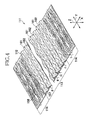
- Fig. 4 is a partially cutaway perspective view of a sheet 111 to be used as the topsheet 11.
- the sheet 111 is a nonwoven fabric formed of short fibers 112 of thermoplastic synthetic resin having a fineness in a range of 1 to 8dtex and previously treated to become hydrophilic wherein these short fibers 112 are interlaced and fused together.
- This sheet 111 has an upper surface 158 and a lower surface 157 and has a mass per unit area in a range of 10 to 60g/m 2 .
- the short fibers 112 have a fiber length in a range of 5 to 80mm and the fiber length of the short fibers 112 is uniform or different as the case may be.
- the short fibers 112 are straight or mechanically or thermally crimped as the case may be.
- the thermoplastic synthetic resin forming the short fibers 112 for example, polyethylene, polypropylene, nylon or polyester may be used.
- the short fibers 112 it is possible to use core-in-sheath type or side-by-side type conjugate fibers made from at least two of the aforementioned various kinds of thermoplastic synthetic resins.
- Central region in a first direction X of the sheet 111 corresponding to the width direction B of the diaper 1 in Fig. 1 is formed with an undulating region 113 and, on both sides of the undulating region 113, flat regions 114 are formed.
- the undulating region 113 is formed on its upper surface 158 with ridges 161 and troughs 162 alternating in the first direction X at a pitch in a range of 2 to 7mm. These ridges 161 and troughs 162 extend in parallel to each other in a second direction Y corresponding to the front-back direction A of the diaper 1. A dimension H in a third direction Z orthogonal to the first direction X and the second direction Y between an upper surface 158 and a lower surface 157 of the ridges 161 corresponds to a height of the ridges 161.
- this dimension H will be sometimes referred to as a "thickness of the sheet 111" and the third direction Z will be sometimes referred to as a "thickness direction of the sheet 111".
- a dimension f is the dimension between the upper surface 158 and the lower surface 157 in the troughs 162 (See Fig. 2 ) .
- a mass per unit area in the flat region 114 is the same as that in the undulating region 113 and a dimension between the upper surface 158 and the lower surface 157 in the flat region 114 is denoted by t (See Fig. 2 ).
- the upper surface 158 and the lower surface 157 of the sheet 111 respectively become the outer surface 58 and the inner surface 57 of the topsheet 11.
- the undulating region 113 and the flat region 114 respectively become the central region 60a and the lateral regions 60b, and the ridges 161 and the troughs 162 respectively become the ridges 61 and the troughs 62.
- the dimension H is in a range of 0.6 to 2mm
- the dimension f is in a range of 0.4 to 0.6mm
- the dimension t is in a range of 0.2 to 0 . 7mm.
- These dimensions H, f , t may be measured by a method as follows.
- the dimension H is measured by placing a pressure plate adapted to exert a surface pressure of 3gf/cm 2 on a plurality of ridges 161 arranged in the first direction X, then putting a contact shoe of a dial gauge into contact with the pressure plate to obtain a measured value and subtracting a thickness of the pressure plate from a measured value.
- the pressure plate may be placed on the flat region 114 and the dial gauge may be used to the dimension t .
- the dimension f may be measured by a method as follows.
- the Replacement Blade HA-100 for Cutter Knife manufactured by Kokuyo Co., LTD. is used to cut the sheet 111 in the first direction X and thereby to prepare a cut surface which is parallel to the first direction X .
- This cut surface is observed through Digital Microscope VHX-900 manufactured by Keyence Corporation and a photograph thereof of 25-fold magnifications is taken. Based on this photograph, a distance in the third direction Z between the short fibers forming the upper surface 158 and the short fibers forming the lower surface 157 in the troughs 162 is measured and the measured distance is obtained as the dimension f.
- the backsheet 12 of the chassis 2 is formed of a thermoplastic synthetic resin film, for example, of polyethylene having a thickness in a range of 0.01 to 0.05mm and the outer sheet 14 is formed of a nonwoven fabric such as, for example, a spunbonded nonwoven fabric, a melt blown nonwoven fabric or a spun laced nonwoven fabric.
- a poorly liquid-pervious or, more preferably a liquid-impervious nonwoven fabric or thermoplastic synthetic resin film may be used.
- a nonwoven fabric or a laminate of a nonwoven fabric and a thermoplastic synthetic resin film may be used.
- Fig. 5 is a diagram illustrating a part of a process for manufacturing a first nonwoven fabric 130a as material of the sheet 111 in Fig. 4 from a carded web 100
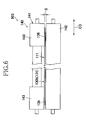
- Fig. 6 is a diagram illustrating a part of a process for manufacturing a continuous web 131 of the sheet 111 from the first nonwoven fabric 130a wherein the process illustrated in Fig. 5 is known from JP 2009-030218 A (PTL 3).
- the carded web 100 formed of the short fibers 112 and having a mass per unit area in a range of 10 to 60g/m 2 are placed on a running belt 200 serving as a supporting means and having air-permeability in the thickness direction and runs in a machine direction MD.
- a running belt 200 serving as a supporting means and having air-permeability in the thickness direction and runs in a machine direction MD.
- a mesh plate having openings, for example, of 30 meshes or more may be used.
- the process includes a first step 901 which is a pre-processing step adapted to compress the carded web 100 in its thickness direction to fuse the short fibers 112 (See Fig.
- the carded web 100 is subjected to ejection of heated first air jets 911 from a first nozzle array 910 and the first air jets 911 are sucked by a first suction box 912 through the carded web 100 and the belt 200.
- Airflow rate of the first air jets 911 is regulated to a level comparable to or a level slightly larger than an intake volume of the first suction box 912 so that such a pre-processing may be implemented.
- Temperature of the first air jets 911 is set to a temperature at which the short fibers 112 may be fused together.
- the pre-processed carded web 100a having been preliminarily processed in the first step 901 is subjected to ejection of a plurality of heated second air jets 921 from a second nozzle array 920 including a plurality of nozzles (not shown) arranged in a cross direction CD at a center-to-center distance a and thereby the first nonwoven fabric 130a is obtained.
- the second air jets 921 partially migrate the short fibers 112 in the pre-processed carded web 100a having its formation stabilized in the first step 901 in the cross direction CD so that the pre-processed carded web 100amaybe formed along portions corresponding to spaces defined between respective pairs of the adjacent second air jets 921 with the ridges 161.
- airflow rate from the second nozzle array 920 is preferably set to be larger than intake volume of the second suction box 925.
- respective positions of the second air jets 921 arranged at the center-to-center distances a in the cross direction CD correspond to positions of the troughs 7 in the nonwoven fabric 1 illustrated in Fig. 4 .
- the second step 902 may include a heat treatment chamber downstream of the second nozzle array 920.
- the first nonwoven fabric 130a may be heated so that surfaces of the respective short fibers 112 may be slightly molten so as to increase the number of regions in which the short fibers 112 in the first nonwoven fabric 130a are fused together and thereby to stabilize the formation of the first nonwoven fabric 130a.
- a second nonwoven fabric 130b cut from the first nonwoven fabric 130a and a desired dimension (width) in the cross direction CD is heat-pressure treated by a pressure roll 140 to obtain the continuous web 131 of the sheet 111.
- the pressure roll 140 includes an upper roll 141 and a lower roll 142 rotating in the machine direction MD.
- the upper roll 141 has diameter-enlarged sections 143 on both end sections in the cross direction CD and these diameter-enlarged sections 143 are heated at a desired temperature.
- the lower roll 142 supports the second nonwoven fabric 130b from below as viewed in Fig. 6 .
- the diameter-enlarged sections 143 of the upper roll 141 cooperate with the lower roll 142 to compress opposite lateral regions 136 in the cross direction CD of the second nonwoven fabric 130b under heating effect.
- the lower roll 142 may be used in a state heated to a desired temperature and may be also used in a state not heated.
- a clearance S between the diameter-enlarged sections 143 and the lower roll 142 is adjusted so that the opposite lateral regions 136 of the second nonwoven fabric 130b may be compressed to a desired thickness.
- a peripheral velocity of the diameter-enlarged sections 143 and the lower roll 142 is also adjusted so that a time required to compress the opposite lateral regions 136 to the desired thickness may be assured.
- the second nonwoven fabric 130b may be compressed by the diameter-enlarged sections 143 heated at a temperature 3 to 20°C lower than the melting temperature of the thermoplastic synthetic resin forming the short fibers 112 and then rapidly cooled to the room temperature. In this way, the compressed and deformed short fibers 112 may be maintained in such a deformed state and the opposite laterals 136 may be changed to the thinner flat regions 114 (See Fig. 3 ) having a thickness t (See Fig. 2 ) as a result of disappearance of the ridges 161.
- the second nonwoven fabric 130b having the opposite lateral regions 136 having been changed in this manner corresponds to the continuous web of the sheet 111.
- this continuous web may be cut into individual sheets having a desired dimension in the machine direction MD and thereby to obtain the individual sheets 111 used as the topsheet 11 of the diaper 1.
- this continuous web may be cut into individual sheets having a desired dimension in the machine direction MD and thereby to obtain the individual sheets 111 used as the topsheet 11 of the diaper 1.
- a density in one of the ridges 161 and the troughs 162 becomes higher than a density in the other.
- the short fibers 112 are apt to be oriented upward in the ridges 161.
- the number of the short fibers 112 per unit area of the sheet 111 is relatively low and the fiber interstices are correspondingly enlarged.
- the upper surface 158 thereof in the flat region 114 is substantially flat in contrast with the upper surface 158 thereof in the undulating region 113.
- the proximal side edges 33 of the respective leakage-barriers 31 may be more reliably bonded to the topsheet 11 in the flat regions 114 than in the undulating region 113 with hot melt adhesive 32a in view of the available area for bonding and the durability of the bonding effect between the proximal side edges 33 and the topsheet 11.
- the density of the short fibers 112 becomes higher than that in the undulating region 113 and, in addition to this, the short fibers 112 having been apt to be oriented in the height direction, i.e., in the thickness direction changes orientation thereof so as to lie in the first direction X and the second direction Y.
- the opposite lateral regions 18 are the regions not including the core material assembly 13 between the topsheet 11 and the backsheet 12 and therefore having no significant water-absorptive property.
- bodily fluids flowing in the width direction B in the crotch region 6 may be dispersed in the lateral regions 60b of the topsheet 11 to prevent or to restrict bodily fluids from staying in the lateral regions 18 of the crotch region 6 and thereby to prevent leakage of bodily fluids from occurring in the crotch region 6.
- ridges 61 and troughs 62 define the opposite side edges 18 of the chassis 2 in the crotch region 6 because such side edges 18 may cause bodily fluids to stay in the crotch region 6.
- the lateral regions 60 defined by the flat portions of the topsheet 11 are partially interposed between the backsheet 12 and the proximal side edges 33 of the leakage-barriers 31, bodily fluids having been dispersed to the lateral regions 60b should not be further dispersed outward because the liquid-impervious backsheet 12 and the poorly-liquid-pervious or liquid-impervious leakage-barriers 31 are bonded together.
- Fig. 7 is a diagram exemplarily illustrating the third step 903 which may be used as an alternative for the third step 903 illustrated in Fig. 6 .
- the upper roll 141 of the roll 140 includes a first upper roll 141a and a second upper roll 141b having respective rotating shafts opposed to each other in the cross direction CD and these first and second upper rolls 141a, 141b heated at a desired temperature cooperate with a lower roll 142 heated as occasion arises to compress the opposite lateral regions 136 of the second nonwoven fabric 130b under heating effect.
- a hot air blower unit 146 Between the first upper roll 141a and the second upper roll 141b, there is provided a hot air blower unit 146.
- the hot air blower unit 146 has a plurality of nozzles 147 arranged at desired pitches in the cross direction CD and hot air heated at a desired temperature is ejected from the respective nozzles 147.
- the second nonwoven fabric 130b corresponds to the web 100 having been treated in the first and second steps 901, 902 illustrated in Fig. 5 and, after being treated in the second step 902, the second nonwoven fabric 130b is once rolled up and sometimes stored in such a rolled up state for several weeks or even for several months. In the second nonwoven fabric 130b having been stored in the rolled up state for such a long period, the ridges 161 are compressed due to being left in such a rolled up state and sometimes deformed to substantially flat shapes.
- the third step 903 illustrated in Fig. 7 is suitably used as the step to obtain the sheet 111 of the topsheets 11 from the second nonwoven fabric 130b having been stored in the rolled up state.
- the initial shapes of the respective ridges 161 have been deformed and substantially collapsed may be restored by heat treatment and thereby the undulating regions 113 essentially required for the sheet 111 and the flat regions 114 of the sheet 111 may be restored without compressing or, if necessary, by compressing the opposite lateral regions 136 of the second nonwoven fabric 130b or compressing them under heating effect or not as the case may be.
- the endless belt may be in the form of an air-permeable mesh-type belt allowing the hot air ejected downward from the nozzle array 147 set up above the endless belt and passing through the nonwoven fabric 136b to flow further downward or in the form of an air-impervious stainless steel belt or in the form of a fabric belt adapted to reflex the hot air toward the nonwoven fabric 136b. It is also possible to exert suction effect to the hot air from underside of the air-permeable belt.
- Fig. 8 is a partially cutaway perspective view of a sanitary napkin as one example of the bodily fluid absorbent wearing article according to this invention and Fig. 9 is a sectional view taken along line IX-IX in Fig. 8 .
- the sanitary napkin 401 has a front-back direction A, a width direction B and a thickness direction C being orthogonal to each other and is shaped to be relatively long in the front-back direction A.
- the sanitary napkin 401 has a chassis 402 including a liquid-pervious topsheet 411, a liquid-impervious backsheet 412 and a bodily fluid absorbent core material assembly 413 interposed between these two sheets 411, 412 wherein the chassis 402 is formed along opposite side edges 418 thereof extending in parallel to each other in the front-back direction A with leakage-barriers 431, respectively.
- the topsheet 411 and the backsheet 412 extend outward beyond a peripheral edge 451 of the core material assembly 413 and are overlapped together outside the peripheral edge 451 of the core material assembly 413 and joined to each other with adhesive or heat sealing to define, in addition to the opposite side edges 418, opposite ends 421.
- the topsheet 411 is made of the short fibers 112 exemplarily illustrated in Fig. 3 and has the central region 60a including the ridges 61 and the troughs 62 and the relatively flat lateral regions 60b in which at least the ridges 61 of the ridges 61 and the troughs 62 are in a compressed state.
- the boundary regions 465 defined between the central region 60a and the lateral regions 60b rectilinearly extend in the front-back direction A along the opposite side edges 418 of the peripheral edge 451 of the core material assembly 413.
- the backsheet 412 is formed of a thermoplastic synthetic resin film and extends outward in the width direction B beyond the opposite side edges 416 of the topsheet 411.
- the leakage-barriers 431 respectively have the proximal side edges 433 bonded to the opposite side edges 418 of the chassis 402 with hot melt adhesive 32a, the opposite ends 436 fixed to the opposite ends 421 and the free side edges 437 extending in the front-back direction A in parallel to the proximal side edges 433 wherein the elastic members 439 are attached under tension to the respective free side edges 437.
- the proximal side edges 433 are bonded not only to the backsheet 412 but also to the flat lateral regions 60b in the topsheet 411 with hot melt adhesive 432a.
- the free side edges 437 of the respective leakage-barriers 431 rise as indicated by imaginary lines in Fig. 9 under contraction of the elastic members 439.
- the proximal side edges 433 of the respective leakage-barriers 431 are bonded to the topsheet 411 in the lateral regions 60b and thereby a sufficient area for bonding may be more easily assured in comparison to the case in which the proximal side edges 433 are bonded to the topsheet 411 in the undulating regions including the ridges 61.
- the opposite lateral regions 60b of the topsheet 411 function in the same manner as the opposite lateral regions 60b of the topsheet 11 in the diaper 1.
- bodily fluids flowing in the width direction B of the sanitary napkin 401 may be dispersed in the front-back direction A.
- the arrangement of the boundary regions 465 defined between the central region 60a and the lateral regions 60b is not limited to the exemplarily illustrated arrangement such that the boundary regions 465 overlap the peripheral edge 451.
Description
- This invention relates to disposable bodily fluid absorbent wearing articles such as disposable diapers and sanitary napkins.
- Conventionally, disposable bodily fluid absorbent wearing articles such as disposable diapers and sanitary napkins including a core material assembly interposed between a liquid-pervious topsheet and a liquid-impervious backsheet are known. It is also known to form the topsheet with ridges and troughs extending in parallel to each other in one direction and arranged alternately in a direction being orthogonal to the direction so that these ridges and troughs face the wearer's skin.
- For example,
JP S58-132155 A -
JP 2008-25079 A -
JP 2009-030218 A -
- {PTL 1}
JP S58-132155 A - {PTL 2}
JP 2008-25079 A - {PTL 3}
JP 2009-030218 A -
- In the bodily fluid absorbent wearing articles such as disposable diapers and sanitary napkins, opposite side edges of the article are provided with the leakage-barriers in order to prevent bodily fluids from leaking out beyond these side edges and, between the opposite leakage-barriers, the bodily fluid absorbent core material assembly is sandwiched between the liquid-pervious topsheet and the liquid-impervious backsheet. When the topsheet disclosed in any one of PTL 1 through 3 is used, it is possible to ensure a sufficient volume of air-permeable clearances between the article wearer's skin and the topsheet and, in contrast with the case in which the topsheet of which both surfaces are flat, correspondingly the contact area between the skin and the topsheet may be reduced. However, when it is tried to bond the proximal side edges of the respective leakage-barriers formed of the belt-like sheet strips to the topsheet, it is easy to bond the proximal side edges to the ridges of the nonwoven fabric but it is not necessarily easy to bond the proximal side edges to the troughs. To overcome such inconvenience, it will be required to enlarge the dimension of the proximal side edges in the width direction compared to the case in which the proximal side edges are bonded to the flat surface of the nonwoven fabric.
- An object of the present invention is to improve the conventional disposable bodily fluid absorbent wearing article so that leakage-barriers may be easily attached to the topsheet being formed with the ridges and the troughs extending in parallel to each other.
- In such a wearing article, this invention resides in that the topsheet extends outward in the width direction at least partially beyond opposite side edges of the core material assembly to define lateral regions extending outside the core material assembly and, in these lateral regions, the ridges are in a compressed state to become lower in height.
- According to one embodiment of this invention, the topsheet is in a compressed state also in part of a central region defined inboard of the lateral regions in the width direction to become lower in height than the ridges.
- According to further another embodiment of this invention, the wearing article is a sanitary napkin.
- According to yet another embodiment of this invention, the wearing article is a disposable diaper including a crotch region extending in the front-back direction, a front waist region lying in front of the crotch region and a rear waist region lying behind the crotch region and the core material assembly is contained at least in the crotch region of these regions.
- According to an alternative embodiment of this invention, the lateral regions of the topsheet extending in the width direction beyond the opposite side edges of the core material assembly are overlapped and bonded together with the backsheet and the respective ones of the opposite side edges of the belt-like sheet strips forming the respective leakage-barriers are overlapped and bonded together outside the respective lateral regions of the topsheet as viewed in the width direction.
- According to another alternative embodiment of this invention, the ridges contain the short fibers oriented in a height direction of the ridges.
- In the disposable bodily fluid absorbent wearing article according to this invention including the topsheet formed on its outer surface with the ridges and the troughs alternately arranged, the opposite lateral regions of the topsheet extending outward at least partially beyond the opposite side edges of the bodily fluid absorbent core material assembly are in a state such that the ridges have been compressed and the thickness of the topsheet has been reduced. In such a topsheet, the opposite lateral regions are sufficiently flattened to assure that the proximal side edges of the respective leakage-barriers may be easily bonded to the opposite lateral regions of the topsheet.
-
- {
Fig. 1} Fig. 1 is a partially cutaway plan view of a diaper. - {
Fig. 2} Fig. 2 is a sectional view taken along line II-II inFig. 1 . - {
Fig. 3} Fig. 3 is a sectional view taken along line III-III inFig. 1 . - {
Fig. 4} Fig. 4 is a partially cutaway plan view of an individually cut out sheet defining a topsheet. - {
Fig. 5} Fig. 5 is adiagrampartially illustratingamanufacturing process for the individually cut out sheet. - {
Fig. 6} Fig. 6 is adiagrampartially illustrating amanufacturing process for the individually cut out sheet. - {
Fig. 7} Fig. 7 is a diagram similar toFig. 6 , illustrating one embodiment of the manufacturing process. - {
Fig. 8} Fig. 8 is a partially cutaway perspective view of a sanitary napkin. - {
Fig. 9} Fig. 9 is a sectional view taken along a line IX-IX inFig. 8 . - Details of a disposable bodily fluid absorbent wearing article according to this invention will be described hereunder with reference to the accompanying drawings.
-
Fig. 1 is a partially cutaway plan view of an open-type disposable diaper 1 as an example of the wearing article according to this invention. The diaper 1 has a front-back direction A and a width direction B being orthogonal to each other, and includes arectangular chassis 2 shaped to be relatively long in the front-back direction A, a pair offront wings 3 attached to a front section of thechassis 2 so as to extend in the width direction B and a pair ofrear wings 4 attached to a rear section of thechassis 2 so as to extend in the width direction B. In the front-back direction A of thechassis 2, acrotch region 6 is defined between thefront wings 3 and therear wings 4, afront waist region 7 is defined in front side of thecrotch region 6 and arear waist region 8 is defined in rear side of thecrotch region 6. - The
chassis 2 includes a liquid-pervious topsheet 11, a liquid-impervious backsheet 12 and a bodily fluid absorbentcore material assembly 13 interposed between these twosheets backsheet 12 is covered with anouter sheet 14 made of a nonwoven fabric having a comfortable texture. Thetopsheet 11 and thebacksheet 12 extend outward beyond aperipheral regions 51 of thecore material assembly 13 and are overlapped together outside theperipheral regions 51 and bonded to each other with hot melt adhesive (not shown). While thetopsheet 11 and thebacksheet 12 exemplarily illustrated are dimensioned to be the same in the front-back direction A, in the width direction B, thebacksheet 12 extends outward beyondopposite side edges 16 of thetopsheet 11. While theouter sheet 14 is dimensioned to be the same as thebacksheet 12 in the front-back direction A, in the width direction B, theouter sheet 14 extends beyondopposite side edges 17 of thebacksheet 12. Respective outer extensions of thesetopsheet 11,backsheet 12 andouter sheet 14 beyond thecore material assembly 13 defineopposite side edges 18 and front andrear ends chassis 2. Along theopposite side edges 18, paired leakage-barriers 31 are formed of individually cut out sheets which are relatively long in the front-back direction A. These leakage-barriers 31 respectively includeproximal side edges 33 bonded to theside edges 18 with hot melt adhesive 32a,front ends 34 bonded to thefront end 21 with hot melt adhesive 32b,rear ends 36 bonded to therear end 22 with hot melt adhesive 32c, andfree side edges 37 lying on the inner side of thechassis 2 compared to theproximal side edges 33 and separably overlapping thetopsheet 11 wherein the respectivefree side edges 37form sleeves 38 andelastic members 39 are attached under tension to inner sides of therespective sleeves 38 with hot melt adhesives (not shown). - Along the
opposite side edges 18 of thechassis 2, legelastic members 41 are disposed between theouter sheet 14 and theproximal side edges 33 of the respective leakage-barriers 31 and attached under tension in the front-back direction A to theouter sheet 14 with hot melt adhesives (not shown). Along thefront end 21 of thechassis 2, front waistelastic members 42 are disposed between thetopsheet 11 and thebacksheet 12 and bonded under tension in the width direction B to at least one of thesesheets rear end 22 of thechassis 2, rear waistelastic members 43 are disposed between thetopsheet 11 and thebacksheet 12 and bonded under tension in the width direction B to at least one of these twosheets - The
chassis 2 formed in the manner as described above is provided on theopposite side edges 18 in thefront waist region 7 with thefront wings 3 extending outward in the width direction B and on theopposite side edges 18 in therear waist region 8 with therear wings 4 extending outward in the width direction B. Therear wings 4 respectively havetape fasteners 46 attached thereto. When it is desired to put the diaper 1 on the wearer's body, thetape fasteners 46 may be extended outward in the width direction B as indicated by imaginary lines and may be releasably fastened to the outer surface of thechassis 2 or to the outer surface of thefront winds 3 with pressure-sensitive adhesive 47 applied to the inner surfaces of therespective tape fasteners 46. - The diaper 1 having
such chassis 2 is symmetric about a center line L bisecting the width of thechassis 2 and when thechassis 2 is bowed in the front-back direction A with thetopsheet 11 inside to be U-shaped, thefree side edges 37 of the leakage-barriers 31 are spaced apart from thetopsheet 11 under contraction of theelastic members 39 and the leakage-barriers 31 rise on thetopsheet 11 as will be illustrated later inFig. 2 . The leakage-barriers 31 standing up in this manner function to prevent bodily fluids flowing on thetopsheet 11 of thecrotch region 6 in the width direction B from leaking out of the diaper 1. -
Fig. 2 is an enlarged sectional view taken along line II-II inFig. 1 wherein a thickness direction of the diaper 1 is indicated by a double-headed arrow C. Referring toFig. 2 , thecore material assembly 13 occupies at least a midsection in the width direction B of thecrotch region 6 and including water-absorptive material 52 such as fluff wood pulp and superabsorbent polymer particles wrapped with awrapping sheet 53 formed of, for example, tissue paper or a liquid-pervious nonwoven fabric which is liquid-pervious, preferably not only liquid-pervious but also liquid-absorptive, and even more preferably, in addition to these two properties, liquid-dispersant. Thecore material assembly 13 has anupper surface 54 covered with thetopsheet 11 and alower surface 56 covered with thebacksheet 12. Along theopposite side edges 18 of thechassis 2 defined by thetopsheet 11, thebacksheet 12 and theouter sheet 14, theproximal side edges 33 of the respective leakage-barriers 31 are bonded to thetopsheet 11, thebacksheet 12 and theouter sheet 14 opposed to the respectiveproximal side edges 33 with hot melt adhesive 32a. The situation in which the free side edges 37 of the respective leakage-barriers 31 andintermediate portions 35 defined between the free side edges 37 and the proximal side edges 33, respectively, are standing up on thetopsheet 11 is indicated by imaginary lines. - Referring again to
Fig. 2 , thetopsheet 11 has aninner surface 57 facing thecore material assembly 13 and anouter surface 58 opposite to theinner surface 57 wherein theinner surface 57 is substantially flat. Acentral region 60a of theouter surface 58 defined inboard ofperipheral regions 51 of thecore material assembly 13 in thecrotch region 6 is formed withridges 61 andtroughs 62 alternating in the width direction B andlateral regions 60b of theouter surface 58 extending outward from theperipheral regions 51 are flat except regions in contact with theperipheral regions 51. A thickness t of thetopsheet 11 in thelateral regions 60b is smaller than a height H of theridges 61 in thecentral region 60a. The proximal side edges 33 of the respective leakage-barriers 31 are bonded to thetopsheet 11 in the flatlateral regions 60b thereof. With the diaper put on the wearer's body, thecentral region 60a of thetopsheet 11 may easily come in contact with the wearer's skin at therespective ridges 61 but not easily come in contact with the wearer's skin at therespective troughs 62 and, in consequence, air passages may be formed between the wearer's skin and thetopsheet 11 along therespective troughs 62 extending in the front-back directionA. Boundary regions 65 between thecentral region 60a and the respectivelateral regions 60b inFig. 2 are indicated by imaginary lines. -
Fig. 3 is a sectional view taken along line III-III inFig. 1 . Thecore material assembly 13 partially hidden behind thetopsheet 11 as indicated by dotted line inFig. 1 has a known hourglass-shape having its width narrowest in thecrotch region 6 and gradually enlarged toward thefront waist region 7 and therear waist region 8. The line III-III extends across thecore material assembly 13 in its region having an enlarged width. Theboundary regions 65 between thecentral region 60a and thelateral regions 60b rectilinearly extend in parallel to the center line L (SeeFig. 1 ) in the front-back direction A. InFig. 2 , theseboundary regions 65 lie adjacent to theperipheral regions 51 but inFig. 3 , the positions of theperipheral regions 51 are shifted outward in the width direction B and, in consequence, therespective boundary regions 65 are spaced from the associatedperipheral regions 51. As will be apparent fromFigs. 2 and3 , the flatlateral regions 60b of thetopsheet 11 are defined in at least portions of theperipheral regions 51 of thecore material assembly 13 extending in the front-back direction A, more specifically, defined outboard of a portion of theperipheral regions 51 of thecore material assembly 13 having a narrowest width. -
Fig. 4 is a partially cutaway perspective view of asheet 111 to be used as thetopsheet 11. Thesheet 111 is a nonwoven fabric formed ofshort fibers 112 of thermoplastic synthetic resin having a fineness in a range of 1 to 8dtex and previously treated to become hydrophilic wherein theseshort fibers 112 are interlaced and fused together. Thissheet 111 has anupper surface 158 and alower surface 157 and has a mass per unit area in a range of 10 to 60g/m2. Theshort fibers 112 have a fiber length in a range of 5 to 80mm and the fiber length of theshort fibers 112 is uniform or different as the case may be. Furthermore, theshort fibers 112 are straight or mechanically or thermally crimped as the case may be. As the thermoplastic synthetic resin forming theshort fibers 112, for example, polyethylene, polypropylene, nylon or polyester may be used. As theshort fibers 112, it is possible to use core-in-sheath type or side-by-side type conjugate fibers made from at least two of the aforementioned various kinds of thermoplastic synthetic resins. Central region in a first direction X of thesheet 111 corresponding to the width direction B of the diaper 1 inFig. 1 is formed with anundulating region 113 and, on both sides of theundulating region 113,flat regions 114 are formed. Theundulating region 113 is formed on itsupper surface 158 withridges 161 andtroughs 162 alternating in the first direction X at a pitch in a range of 2 to 7mm. Theseridges 161 andtroughs 162 extend in parallel to each other in a second direction Y corresponding to the front-back direction A of the diaper 1. A dimension H in a third direction Z orthogonal to the first direction X and the second direction Y between anupper surface 158 and alower surface 157 of theridges 161 corresponds to a height of theridges 161. In this invention, this dimension H will be sometimes referred to as a "thickness of thesheet 111" and the third direction Z will be sometimes referred to as a "thickness direction of thesheet 111". A dimension f is the dimension between theupper surface 158 and thelower surface 157 in the troughs 162 (SeeFig. 2 ) . A mass per unit area in theflat region 114 is the same as that in theundulating region 113 and a dimension between theupper surface 158 and thelower surface 157 in theflat region 114 is denoted by t (SeeFig. 2 ). - When such a
sheet 111 is used as thetopsheet 11 inFigs. 1 to 3 , theupper surface 158 and thelower surface 157 of thesheet 111 respectively become theouter surface 58 and theinner surface 57 of thetopsheet 11. Theundulating region 113 and theflat region 114 respectively become thecentral region 60a and thelateral regions 60b, and theridges 161 and thetroughs 162 respectively become theridges 61 and thetroughs 62. - In the
preferred sheet 111, the dimension H is in a range of 0.6 to 2mm, the dimension f is in a range of 0.4 to 0.6mm and the dimension t is in a range of 0.2 to 0 . 7mm. These dimensions H, f, t may be measured by a method as follows. The dimension H is measured by placing a pressure plate adapted to exert a surface pressure of 3gf/cm2 on a plurality ofridges 161 arranged in the first direction X, then putting a contact shoe of a dial gauge into contact with the pressure plate to obtain a measured value and subtracting a thickness of the pressure plate from a measured value. Similarly to the measuring method for the dimension H, the pressure plate may be placed on theflat region 114 and the dial gauge may be used to the dimension t. The dimension f may be measured by a method as follows. The Replacement Blade HA-100 for Cutter Knife manufactured by Kokuyo Co., LTD. is used to cut thesheet 111 in the first direction X and thereby to prepare a cut surface which is parallel to the first direction X . This cut surface is observed through Digital Microscope VHX-900 manufactured by Keyence Corporation and a photograph thereof of 25-fold magnifications is taken. Based on this photograph, a distance in the third direction Z between the short fibers forming theupper surface 158 and the short fibers forming thelower surface 157 in thetroughs 162 is measured and the measured distance is obtained as the dimension f. - In the diaper 1 exemplarily illustrated in
Fig. 1 , thebacksheet 12 of thechassis 2 is formed of a thermoplastic synthetic resin film, for example, of polyethylene having a thickness in a range of 0.01 to 0.05mm and theouter sheet 14 is formed of a nonwoven fabric such as, for example, a spunbonded nonwoven fabric, a melt blown nonwoven fabric or a spun laced nonwoven fabric. As material for the leakage-barriers 31, a poorly liquid-pervious or, more preferably a liquid-impervious nonwoven fabric or thermoplastic synthetic resin film may be used. As material for thefront wings 3 and therear wings 4, a nonwoven fabric or a laminate of a nonwoven fabric and a thermoplastic synthetic resin film may be used. -
Fig. 5 is a diagram illustrating a part of a process for manufacturing a firstnonwoven fabric 130a as material of thesheet 111 inFig. 4 from a cardedweb 100 andFig. 6 is a diagram illustrating a part of a process for manufacturing acontinuous web 131 of thesheet 111 from thefirst nonwoven fabric 130a wherein the process illustrated inFig. 5 is known fromJP 2009-030218 A - Referring to
Fig. 5 , the cardedweb 100 formed of theshort fibers 112 and having a mass per unit area in a range of 10 to 60g/m2 are placed on a runningbelt 200 serving as a supporting means and having air-permeability in the thickness direction and runs in a machine direction MD. As the runningbelt 200, a mesh plate having openings, for example, of 30 meshes or more may be used. In the machine direction MD, the process includes afirst step 901 which is a pre-processing step adapted to compress the cardedweb 100 in its thickness direction to fuse the short fibers 112 (SeeFig. 3 ) together and thereby to stabilize formation of the cardedweb 100 and asecond step 902 adapted to form a pre-processed cardedweb 100a with theridges 161 and thetroughs 162. In thefirst step 901, the cardedweb 100 is subjected to ejection of heatedfirst air jets 911 from afirst nozzle array 910 and thefirst air jets 911 are sucked by afirst suction box 912 through the cardedweb 100 and thebelt 200. Airflow rate of thefirst air jets 911 is regulated to a level comparable to or a level slightly larger than an intake volume of thefirst suction box 912 so that such a pre-processing may be implemented. Temperature of thefirst air jets 911 is set to a temperature at which theshort fibers 112 may be fused together. - In the
second step 902, the pre-processed cardedweb 100a having been preliminarily processed in thefirst step 901 is subjected to ejection of a plurality of heatedsecond air jets 921 from asecond nozzle array 920 including a plurality of nozzles (not shown) arranged in a cross direction CD at a center-to-center distance a and thereby thefirst nonwoven fabric 130a is obtained. Thesecond air jets 921 partially migrate theshort fibers 112 in the pre-processed cardedweb 100a having its formation stabilized in thefirst step 901 in the cross direction CD so that the pre-processed carded web 100amaybe formed along portions corresponding to spaces defined between respective pairs of the adjacentsecond air jets 921 with theridges 161. To achieve this, airflow rate from thesecond nozzle array 920 is preferably set to be larger than intake volume of thesecond suction box 925. In thesecond step 902, respective positions of thesecond air jets 921 arranged at the center-to-center distances a in the cross direction CD correspond to positions of thetroughs 7 in the nonwoven fabric 1 illustrated inFig. 4 . In thefirst nonwoven fabric 130a, some portions of theshort fibers 112 lying immediately below the respectivesecond air jets 921 migrate in even shares toward both sides in the cross direction CD so as to participate in formation of theridges 161 while the short fibers 121 remaining immediately below thesecond air jets 921 form therespective troughs 162. Though not illustrated, thesecond step 902 may include a heat treatment chamber downstream of thesecond nozzle array 920. In this heat treatment chamber, thefirst nonwoven fabric 130a may be heated so that surfaces of the respectiveshort fibers 112 may be slightly molten so as to increase the number of regions in which theshort fibers 112 in thefirst nonwoven fabric 130a are fused together and thereby to stabilize the formation of thefirst nonwoven fabric 130a. - In a
third step 903 illustrated inFig. 6 , a secondnonwoven fabric 130b cut from thefirst nonwoven fabric 130a and a desired dimension (width) in the cross direction CD is heat-pressure treated by apressure roll 140 to obtain thecontinuous web 131 of thesheet 111. Thepressure roll 140 includes anupper roll 141 and alower roll 142 rotating in the machine direction MD. Theupper roll 141 has diameter-enlargedsections 143 on both end sections in the cross direction CD and these diameter-enlargedsections 143 are heated at a desired temperature. Thelower roll 142 supports the secondnonwoven fabric 130b from below as viewed inFig. 6 . The diameter-enlargedsections 143 of theupper roll 141 cooperate with thelower roll 142 to compress oppositelateral regions 136 in the cross direction CD of the secondnonwoven fabric 130b under heating effect. In this regard, thelower roll 142 may be used in a state heated to a desired temperature and may be also used in a state not heated. A clearance S between the diameter-enlargedsections 143 and thelower roll 142 is adjusted so that the oppositelateral regions 136 of the secondnonwoven fabric 130b may be compressed to a desired thickness. A peripheral velocity of the diameter-enlargedsections 143 and thelower roll 142 is also adjusted so that a time required to compress the oppositelateral regions 136 to the desired thickness may be assured. The secondnonwoven fabric 130b may be compressed by the diameter-enlargedsections 143 heated at atemperature 3 to 20°C lower than the melting temperature of the thermoplastic synthetic resin forming theshort fibers 112 and then rapidly cooled to the room temperature. In this way, the compressed and deformedshort fibers 112 may be maintained in such a deformed state and theopposite laterals 136 may be changed to the thinner flat regions 114 (SeeFig. 3 ) having a thickness t (SeeFig. 2 ) as a result of disappearance of theridges 161. The secondnonwoven fabric 130b having the oppositelateral regions 136 having been changed in this manner corresponds to the continuous web of thesheet 111. Specifically, this continuous web may be cut into individual sheets having a desired dimension in the machine direction MD and thereby to obtain theindividual sheets 111 used as thetopsheet 11 of the diaper 1. Depending on various factors such as the nature of the cardedweb 100 and the operating condition in the first andsecond steps Fig. 5 , generally there is a tendency such that a density in one of theridges 161 and thetroughs 162 becomes higher than a density in the other. Theshort fibers 112 are apt to be oriented upward in theridges 161. In thetroughs 162, there is a tendency such that the number of theshort fibers 112 per unit area of thesheet 111 is relatively low and the fiber interstices are correspondingly enlarged. In thethird step 903 illustrated inFig. 6 , it is possible to set up a blower downstream of theroll 140 to cool the oppositelateral regions 136 of theweb 131. It is also possible to set up an additional roll similar to theroll 140 downstream of theroll 140 to assure sufficiently long time for heating and pressurizing the oppositelateral regions 136. - In the
sheet 111 illustrated inFig. 4 obtained by cutting theweb 131 obtained by following the first tothird steps 901 to 903, theupper surface 158 thereof in theflat region 114 is substantially flat in contrast with theupper surface 158 thereof in theundulating region 113. Consequentially, the proximal side edges 33 of the respective leakage-barriers 31 may be more reliably bonded to thetopsheet 11 in theflat regions 114 than in theundulating region 113 with hot melt adhesive 32a in view of the available area for bonding and the durability of the bonding effect between the proximal side edges 33 and thetopsheet 11. In thesheet 111, the density of theshort fibers 112 becomes higher than that in theundulating region 113 and, in addition to this, theshort fibers 112 having been apt to be oriented in the height direction, i.e., in the thickness direction changes orientation thereof so as to lie in the first direction X and the second direction Y. As an advantageous result, on thetopsheet 11 of the diaper 1 illustrated inFigs. 1 and2 formed of thesheet 111, bodily fluids flowing from the central region in the width direction B of thechassis 2 toward thelateral regions 18 in thecrotch region 6, in other words, bodily fluids flowing from thecentral region 60a toward thelateral regions 60b of thetopsheet 11 may rapidly disperse in the front-back direction A as well as in the width direction B in the oppositelateral regions 60b in which the density is relatively high and theshort fibers 112 are horizontally oriented. The oppositelateral regions 18 are the regions not including thecore material assembly 13 between thetopsheet 11 and thebacksheet 12 and therefore having no significant water-absorptive property. In view of this, bodily fluids flowing in the width direction B in thecrotch region 6 may be dispersed in thelateral regions 60b of thetopsheet 11 to prevent or to restrict bodily fluids from staying in thelateral regions 18 of thecrotch region 6 and thereby to prevent leakage of bodily fluids from occurring in thecrotch region 6. In fact, in theridges 161 and thetroughs 162 of thesheet 111, in other words, in theridges 61 and thetroughs 62 of thetopsheet 11, orientation of theshort fibers 112 in the height direction in theridges 61 and relatively large interstices among theshort fibers 112 in the troughs facilitate bodily fluids in thecrotch region 6 to permeate thetopsheet 11. However, in theridges 61 as well as in thetroughs 62, bodily fluids may not smoothly disperse in the front-back direction A as well as in the width direction B. Considering this, it is not preferable thatsuch ridges 61 andtroughs 62 define the opposite side edges 18 of thechassis 2 in thecrotch region 6 because such side edges 18 may cause bodily fluids to stay in thecrotch region 6. While, referring toFigs. 2 and3 , the lateral regions 60 defined by the flat portions of thetopsheet 11 are partially interposed between thebacksheet 12 and the proximal side edges 33 of the leakage-barriers 31, bodily fluids having been dispersed to thelateral regions 60b should not be further dispersed outward because the liquid-impervious backsheet 12 and the poorly-liquid-pervious or liquid-impervious leakage-barriers 31 are bonded together. -
Fig. 7 is a diagram exemplarily illustrating thethird step 903 which may be used as an alternative for thethird step 903 illustrated inFig. 6 . In the step illustrated inFig.7 , theupper roll 141 of theroll 140 includes a firstupper roll 141a and a secondupper roll 141b having respective rotating shafts opposed to each other in the cross direction CD and these first and secondupper rolls lower roll 142 heated as occasion arises to compress the oppositelateral regions 136 of the secondnonwoven fabric 130b under heating effect. Between the firstupper roll 141a and the secondupper roll 141b, there is provided a hotair blower unit 146. The hotair blower unit 146 has a plurality ofnozzles 147 arranged at desired pitches in the cross direction CD and hot air heated at a desired temperature is ejected from therespective nozzles 147. The secondnonwoven fabric 130b corresponds to theweb 100 having been treated in the first andsecond steps Fig. 5 and, after being treated in thesecond step 902, the secondnonwoven fabric 130b is once rolled up and sometimes stored in such a rolled up state for several weeks or even for several months. In the secondnonwoven fabric 130b having been stored in the rolled up state for such a long period, theridges 161 are compressed due to being left in such a rolled up state and sometimes deformed to substantially flat shapes. Theseridges 161 may be softened by heating them at a temperature not so high to melt theshort fibers 112 to recover the initial or substantially initial shapes thereof. Thethird step 903 illustrated inFig. 7 is suitably used as the step to obtain thesheet 111 of thetopsheets 11 from the secondnonwoven fabric 130b having been stored in the rolled up state. Specifically, in thethird step 903, the initial shapes of therespective ridges 161 have been deformed and substantially collapsed may be restored by heat treatment and thereby the undulatingregions 113 essentially required for thesheet 111 and theflat regions 114 of thesheet 111 may be restored without compressing or, if necessary, by compressing the oppositelateral regions 136 of the secondnonwoven fabric 130b or compressing them under heating effect or not as the case may be. - In the step exemplarily illustrated in
Fig. 7 , it is possible to replace thelower roll 142 by an endless belt (not shown) adapted to run in the machine direction MD (SeeFig. 5 ). The endless belt may be in the form of an air-permeable mesh-type belt allowing the hot air ejected downward from thenozzle array 147 set up above the endless belt and passing through the nonwoven fabric 136b to flow further downward or in the form of an air-impervious stainless steel belt or in the form of a fabric belt adapted to reflex the hot air toward the nonwoven fabric 136b. It is also possible to exert suction effect to the hot air from underside of the air-permeable belt. -
Fig. 8 is a partially cutaway perspective view of a sanitary napkin as one example of the bodily fluid absorbent wearing article according to this invention andFig. 9 is a sectional view taken along line IX-IX inFig. 8 . Thesanitary napkin 401 has a front-back direction A, a width direction B and a thickness direction C being orthogonal to each other and is shaped to be relatively long in the front-back direction A. Thesanitary napkin 401 has achassis 402 including a liquid-pervious topsheet 411, a liquid-impervious backsheet 412 and a bodily fluid absorbentcore material assembly 413 interposed between these twosheets chassis 402 is formed along opposite side edges 418 thereof extending in parallel to each other in the front-back direction A with leakage-barriers 431, respectively. Thetopsheet 411 and thebacksheet 412 extend outward beyond aperipheral edge 451 of thecore material assembly 413 and are overlapped together outside theperipheral edge 451 of thecore material assembly 413 and joined to each other with adhesive or heat sealing to define, in addition to the opposite side edges 418, opposite ends 421. - The
topsheet 411 is made of theshort fibers 112 exemplarily illustrated inFig. 3 and has thecentral region 60a including theridges 61 and thetroughs 62 and the relatively flatlateral regions 60b in which at least theridges 61 of theridges 61 and thetroughs 62 are in a compressed state. Theboundary regions 465 defined between thecentral region 60a and thelateral regions 60b rectilinearly extend in the front-back direction A along the opposite side edges 418 of theperipheral edge 451 of thecore material assembly 413. Thebacksheet 412 is formed of a thermoplastic synthetic resin film and extends outward in the width direction B beyond the opposite side edges 416 of thetopsheet 411. - The leakage-
barriers 431 respectively have the proximal side edges 433 bonded to the opposite side edges 418 of thechassis 402 with hot melt adhesive 32a, the opposite ends 436 fixed to the opposite ends 421 and the free side edges 437 extending in the front-back direction A in parallel to the proximal side edges 433 wherein theelastic members 439 are attached under tension to the respective free side edges 437. As will be apparent fromFig. 9 , the proximal side edges 433 are bonded not only to thebacksheet 412 but also to the flatlateral regions 60b in thetopsheet 411 with hot melt adhesive 432a. - When such a
sanitary napkin 401 is put on the wearer's body and bowed in the front-back direction A in U-shape, the free side edges 437 of the respective leakage-barriers 431 rise as indicated by imaginary lines inFig. 9 under contraction of theelastic members 439. The proximal side edges 433 of the respective leakage-barriers 431 are bonded to thetopsheet 411 in thelateral regions 60b and thereby a sufficient area for bonding may be more easily assured in comparison to the case in which the proximal side edges 433 are bonded to thetopsheet 411 in the undulating regions including theridges 61. The oppositelateral regions 60b of thetopsheet 411 function in the same manner as the oppositelateral regions 60b of thetopsheet 11 in the diaper 1. Specifically, bodily fluids flowing in the width direction B of thesanitary napkin 401 may be dispersed in the front-back direction A. In this invention, the arrangement of theboundary regions 465 defined between thecentral region 60a and thelateral regions 60b is not limited to the exemplarily illustrated arrangement such that theboundary regions 465 overlap theperipheral edge 451. For example, it is also possible to arrange theboundary regions 465 to be contiguous to theperipheral edge 451 from the outside of theperipheral edge 451, or to be contiguous to theperipheral edge 451 from the inside of theperipheral edge 451. -
- 1
- wearing article (diaper)
- 2
- chassis
- 6
- crotch region
- 7
- front waist region
- 8
- rear waist region
- 11
- topsheet
- 12
- backsheet
- 13
- core material assembly
- 31
- leakage-barriers
- 33
- side edges (proximal side edges)
- 37
- side edges (free side edges)
- 51
- side edges
- 57
- inner surface
- 58
- outer surface
- 60a
- central region
- 60b
- lateral regions
- 61
- ridges
- 62
- troughs
- A
- front-back direction
- B
- width direction
Claims (6)
- A disposable bodily fluid absorbent wearing article (1) having a front-back direction (A) corresponding to a front-back direction of wearer's body and a width direction (B) being orthogonal to the front-back direction, including
a bodily fluid absorbent core material assembly (13) interposed between a liquid-pervious topsheet (11) and a liquid-impervious backsheet (12) in a central region as viewed in the width direction wherein
the topsheet is formed of thermoplastic synthetic resin short fibers (112) and formed on its outer surface opposed to its inner surface facing the core material assembly with ridges (61) and troughs (62) extending in the front-back direction in parallel to each other so as to undulate in the width direction and wherein
along opposite outsides in the width direction of the core material assembly, leakage-barriers (31) adapted to be elastically stretched and contracted in the front-back direction and to be spaced apart from the topsheet are formed, and
the topsheet extends outward in the width direction at least partially beyond opposite side edges of the core material assembly to define lateral regions (60b) extending outside the core material assembly, wherein:in these lateral regions, the ridges are in a compressed state to become lower in height and to be flat;the leakage-barriers are formed of belt-like sheet strips;respective ones of opposite side edges of the leakage-barriers extending in the front-back direction in parallel to each other are overlapped and bonded together with the respective lateral regions of the topsheet in the width direction so that the ridges are in a compressed state in zones of the lateral regions overlapping the respective ones of the opposite side edges of the leakage-barriers; andthe ridges are in a compressed state in regions of the topsheet defined between the zones in which the respective ones of the opposite side edges of the leakage-barriers overlapped and bonded together with the lateral regions of the topsheet and the opposite side edges of the core material assembly as viewed in the width direction. - The wearing article defined by Claim 1, wherein the topsheet is in a compressed state also in part of a central region defined inboard of the lateral regions in the width direction to become lower in height than the ridges.
- The wearing article defined by Claim 1 or 2, wherein the wearing article is a sanitary napkin (401).
- The wearing article defined by any one of Claims 1 to 3, wherein the wearing article is a disposable diaper (1) including a crotch region (6) extending in the front-back direction, a front waist region (7) lying in front of the crotch region and a rear waist region (8) lying behind the crotch region and the core material assembly is contained at least in the crotch region of these regions.
- The wearing article defined by any one of Claims 1 to 4, wherein the lateral regions of the topsheet extending in the width direction beyond the opposite side edges of the core material assembly are overlapped and bonded together with the backsheet and the respective ones of the opposite side edges of the belt-like sheet strips forming the respective leakage-barriers are overlapped and bonded together outside the respective lateral regions of the topsheet as viewed in the width direction.
- The wearing article defined by any one of Claims 1 to 5, wherein the ridges contain the short fibers oriented in a height direction of the ridges.
Applications Claiming Priority (2)
| Application Number | Priority Date | Filing Date | Title |
|---|---|---|---|
| JP2009223445A JP5328586B2 (en) | 2009-09-28 | 2009-09-28 | Disposable body fluid absorbent article |
| PCT/JP2010/063764 WO2011036964A1 (en) | 2009-09-28 | 2010-08-13 | Disposable wearing article capable of absorbing bodily fluids |
Publications (3)
| Publication Number | Publication Date |
|---|---|
| EP2484320A1 EP2484320A1 (en) | 2012-08-08 |
| EP2484320A4 EP2484320A4 (en) | 2013-09-18 |
| EP2484320B1 true EP2484320B1 (en) | 2014-11-05 |
Family
ID=43795723
Family Applications (1)
| Application Number | Title | Priority Date | Filing Date |
|---|---|---|---|
| EP10818640.4A Not-in-force EP2484320B1 (en) | 2009-09-28 | 2010-08-13 | Disposable wearing article capable of absorbing bodily fluids |
Country Status (7)
| Country | Link |
|---|---|
| US (1) | US20120226252A1 (en) |
| EP (1) | EP2484320B1 (en) |
| JP (1) | JP5328586B2 (en) |
| CN (1) | CN102573738B (en) |
| AU (1) | AU2010299269A1 (en) |
| EA (1) | EA201290101A1 (en) |
| WO (1) | WO2011036964A1 (en) |
Families Citing this family (15)
| Publication number | Priority date | Publication date | Assignee | Title |
|---|---|---|---|---|
| JP5970228B2 (en) * | 2012-04-19 | 2016-08-17 | 花王株式会社 | Absorbent articles |
| JP5755631B2 (en) | 2012-12-13 | 2015-07-29 | ユニ・チャーム株式会社 | Disposable diapers for pets |
| JP6084451B2 (en) | 2012-12-13 | 2017-02-22 | ユニ・チャーム株式会社 | Disposable diapers for pets |
| JP6084453B2 (en) | 2012-12-13 | 2017-02-22 | ユニ・チャーム株式会社 | Disposable diapers for pets |
| JP5755630B2 (en) | 2012-12-13 | 2015-07-29 | ユニ・チャーム株式会社 | Disposable diapers for pets |
| JP6008729B2 (en) | 2012-12-13 | 2016-10-19 | ユニ・チャーム株式会社 | Disposable diapers for pets |
| JP6084452B2 (en) | 2012-12-13 | 2017-02-22 | ユニ・チャーム株式会社 | Disposable diapers for pets |
| JP5956323B2 (en) | 2012-12-13 | 2016-07-27 | ユニ・チャーム株式会社 | Disposable diapers for pets |
| JP6084450B2 (en) | 2012-12-13 | 2017-02-22 | ユニ・チャーム株式会社 | Disposable diapers for pets |
| JP5829599B2 (en) | 2012-12-13 | 2015-12-09 | ユニ・チャーム株式会社 | Disposable diapers for pets |
| JP5829600B2 (en) | 2012-12-13 | 2015-12-09 | ユニ・チャーム株式会社 | Disposable diapers for pets |
| JP6290538B2 (en) * | 2013-02-07 | 2018-03-07 | ユニ・チャーム株式会社 | Disposable diapers |
| JP5800876B2 (en) * | 2013-09-30 | 2015-10-28 | ユニ・チャーム株式会社 | Absorbent articles |
| JP6175529B1 (en) * | 2016-03-02 | 2017-08-02 | ユニ・チャーム株式会社 | Pants-type disposable diaper |
| KR102536792B1 (en) * | 2021-09-10 | 2023-05-26 | 주식회사 디알컴퍼니 | A pad for incontinence panties with a leak prevention function in the folding band part |
Family Cites Families (18)
| Publication number | Priority date | Publication date | Assignee | Title |
|---|---|---|---|---|
| JPS58132155A (en) * | 1982-01-31 | 1983-08-06 | ユニ・チヤ−ム株式会社 | Production of nonwoven fabric with pattern |
| JP2860730B2 (en) * | 1992-03-26 | 1999-02-24 | 小林製薬株式会社 | Body fluid absorption material |
| JPH07299093A (en) * | 1994-05-10 | 1995-11-14 | Uni Charm Corp | Body fluid absorbent article for wear |
| DE4422956A1 (en) * | 1994-06-30 | 1996-01-04 | Schickedanz Ver Papierwerk | Absorbent hygiene article for absorbing body fluids |
| JP3490291B2 (en) * | 1998-05-18 | 2004-01-26 | ユニ・チャーム株式会社 | Absorbent articles |
| CN1240125A (en) * | 1998-06-03 | 2000-01-05 | 尤妮佳股份有限公司 | Body liquid absorption articles |
| JPH11342154A (en) * | 1998-06-03 | 1999-12-14 | Uni Charm Corp | Humor absorption article |
| EP0983758A1 (en) * | 1998-09-03 | 2000-03-08 | The Procter & Gamble Company | Strong and soft apertured nonwoven web |
| JP2000135239A (en) * | 1998-10-30 | 2000-05-16 | Uni Charm Corp | Disposable humor absorption type wearing article |
| JP3639450B2 (en) * | 1999-01-20 | 2005-04-20 | ユニ・チャーム株式会社 | Disposable absorbent article for body fluid treatment |
| JP3926587B2 (en) * | 2001-07-12 | 2007-06-06 | ユニ・チャーム株式会社 | Absorbent articles |
| US7132585B2 (en) * | 2002-12-05 | 2006-11-07 | Uni-Charm Corporation | Absorbent article with liquid acquisition layer |
| JP4738049B2 (en) * | 2005-05-02 | 2011-08-03 | ユニ・チャーム株式会社 | Absorbent articles |
| JP5123511B2 (en) * | 2006-06-23 | 2013-01-23 | ユニ・チャーム株式会社 | Non-woven |
| JP5054963B2 (en) * | 2006-11-27 | 2012-10-24 | ユニ・チャーム株式会社 | Absorbent articles |
| JP5497987B2 (en) * | 2007-06-22 | 2014-05-21 | ユニ・チャーム株式会社 | Nonwoven fabric and method for producing the same |
| JP5086035B2 (en) * | 2007-11-12 | 2012-11-28 | 花王株式会社 | Absorbent article surface sheet |
| JP5086036B2 (en) * | 2007-11-12 | 2012-11-28 | 花王株式会社 | Absorbent articles |
-
2009
- 2009-09-28 JP JP2009223445A patent/JP5328586B2/en not_active Expired - Fee Related
-
2010
- 2010-08-13 WO PCT/JP2010/063764 patent/WO2011036964A1/en active Application Filing
- 2010-08-13 AU AU2010299269A patent/AU2010299269A1/en not_active Abandoned
- 2010-08-13 EA EA201290101A patent/EA201290101A1/en unknown
- 2010-08-13 CN CN201080043118.2A patent/CN102573738B/en active Active
- 2010-08-13 EP EP10818640.4A patent/EP2484320B1/en not_active Not-in-force
- 2010-08-13 US US13/496,938 patent/US20120226252A1/en not_active Abandoned
Also Published As
| Publication number | Publication date |
|---|---|
| CN102573738A (en) | 2012-07-11 |
| AU2010299269A1 (en) | 2012-05-03 |
| EP2484320A1 (en) | 2012-08-08 |
| EA201290101A1 (en) | 2012-11-30 |
| EP2484320A4 (en) | 2013-09-18 |
| JP5328586B2 (en) | 2013-10-30 |
| CN102573738B (en) | 2015-04-15 |
| WO2011036964A1 (en) | 2011-03-31 |
| US20120226252A1 (en) | 2012-09-06 |
| JP2011067563A (en) | 2011-04-07 |
Similar Documents
| Publication | Publication Date | Title |
|---|---|---|
| EP2484320B1 (en) | Disposable wearing article capable of absorbing bodily fluids | |
| JP3638819B2 (en) | Disposable diapers with back leak prevention function | |
| EP1199059B1 (en) | Body fluid absorbent panel | |
| RU2735227C1 (en) | Absorbent products with visually different base and belt tapes | |
| KR101973345B1 (en) | An absorbent article with an optionally positioned waist-hole preventing member having an improved waist seal | |
| EP0815819B1 (en) | Perforated multilayer topsheet | |
| JP5743961B2 (en) | Liquid-permeable nonwoven fabric | |
| WO2011040042A1 (en) | Disposable diaper | |
| JP6968170B2 (en) | Disposable pants type absorbent goods | |
| KR20110098765A (en) | Disposable absorbent garments employing elastomeric film laminates with deactivated regions | |
| EP1064897B1 (en) | Composite plastic sheet and process for making the same | |
| EP2221033A1 (en) | Absorbent article to be worn | |
| JP5832761B2 (en) | Absorbent wearing articles | |
| US20100268185A1 (en) | Shaped absorbent article with edge elastics | |
| US20030040732A1 (en) | Pants-type disposable diaper | |
| US20220354711A1 (en) | Absorbent article | |
| CN113573678B (en) | Absorbent article having discontinuous bond pattern | |
| JP6004723B2 (en) | Disposable diapers | |
| EP1062927A2 (en) | Liquid-pervious topsheet for disposable absorbent article and process for making the same | |
| JPH11197180A (en) | Absorptive article | |
| WO2013084516A1 (en) | Disposable wearing article | |
| JP4630622B2 (en) | Pants-type disposable diaper | |
| JP3723755B2 (en) | Open disposable diaper | |
| JP6603922B2 (en) | Absorbent articles | |
| US11617692B2 (en) | Absorbent article including a conformance zone which includes absorbent clusters |
Legal Events
| Date | Code | Title | Description |
|---|---|---|---|
| PUAI | Public reference made under article 153(3) epc to a published international application that has entered the european phase |
Free format text: ORIGINAL CODE: 0009012 |
|
| 17P | Request for examination filed |
Effective date: 20120314 |
|
| AK | Designated contracting states |
Kind code of ref document: A1 Designated state(s): AL AT BE BG CH CY CZ DE DK EE ES FI FR GB GR HR HU IE IS IT LI LT LU LV MC MK MT NL NO PL PT RO SE SI SK SM TR |
|
| DAX | Request for extension of the european patent (deleted) | ||
| A4 | Supplementary search report drawn up and despatched |
Effective date: 20130820 |
|
| RIC1 | Information provided on ipc code assigned before grant |
Ipc: A61F 13/15 20060101ALI20130813BHEP Ipc: A61F 13/49 20060101AFI20130813BHEP Ipc: A61F 13/511 20060101ALI20130813BHEP |
|
| GRAP | Despatch of communication of intention to grant a patent |
Free format text: ORIGINAL CODE: EPIDOSNIGR1 |
|
| INTG | Intention to grant announced |
Effective date: 20140613 |
|
| GRAS | Grant fee paid |
Free format text: ORIGINAL CODE: EPIDOSNIGR3 |
|
| GRAA | (expected) grant |
Free format text: ORIGINAL CODE: 0009210 |
|
| AK | Designated contracting states |
Kind code of ref document: B1 Designated state(s): AL AT BE BG CH CY CZ DE DK EE ES FI FR GB GR HR HU IE IS IT LI LT LU LV MC MK MT NL NO PL PT RO SE SI SK SM TR |
|
| REG | Reference to a national code |
Ref country code: GB Ref legal event code: FG4D |
|
| REG | Reference to a national code |
Ref country code: CH Ref legal event code: EP |
|
| REG | Reference to a national code |
Ref country code: AT Ref legal event code: REF Ref document number: 694211 Country of ref document: AT Kind code of ref document: T Effective date: 20141115 |
|
| REG | Reference to a national code |
Ref country code: IE Ref legal event code: FG4D |
|
| REG | Reference to a national code |
Ref country code: DE Ref legal event code: R096 Ref document number: 602010020034 Country of ref document: DE Effective date: 20141211 |
|
| REG | Reference to a national code |
Ref country code: AT Ref legal event code: MK05 Ref document number: 694211 Country of ref document: AT Kind code of ref document: T Effective date: 20141105 |
|
| REG | Reference to a national code |
Ref country code: NL Ref legal event code: VDEP Effective date: 20141105 |
|
| REG | Reference to a national code |
Ref country code: LT Ref legal event code: MG4D |
|
| PG25 | Lapsed in a contracting state [announced via postgrant information from national office to epo] |
Ref country code: NL Free format text: LAPSE BECAUSE OF FAILURE TO SUBMIT A TRANSLATION OF THE DESCRIPTION OR TO PAY THE FEE WITHIN THE PRESCRIBED TIME-LIMIT Effective date: 20141105 Ref country code: IS Free format text: LAPSE BECAUSE OF FAILURE TO SUBMIT A TRANSLATION OF THE DESCRIPTION OR TO PAY THE FEE WITHIN THE PRESCRIBED TIME-LIMIT Effective date: 20150305 Ref country code: PT Free format text: LAPSE BECAUSE OF FAILURE TO SUBMIT A TRANSLATION OF THE DESCRIPTION OR TO PAY THE FEE WITHIN THE PRESCRIBED TIME-LIMIT Effective date: 20150305 Ref country code: ES Free format text: LAPSE BECAUSE OF FAILURE TO SUBMIT A TRANSLATION OF THE DESCRIPTION OR TO PAY THE FEE WITHIN THE PRESCRIBED TIME-LIMIT Effective date: 20141105 Ref country code: NO Free format text: LAPSE BECAUSE OF FAILURE TO SUBMIT A TRANSLATION OF THE DESCRIPTION OR TO PAY THE FEE WITHIN THE PRESCRIBED TIME-LIMIT Effective date: 20150205 Ref country code: LT Free format text: LAPSE BECAUSE OF FAILURE TO SUBMIT A TRANSLATION OF THE DESCRIPTION OR TO PAY THE FEE WITHIN THE PRESCRIBED TIME-LIMIT Effective date: 20141105 Ref country code: FI Free format text: LAPSE BECAUSE OF FAILURE TO SUBMIT A TRANSLATION OF THE DESCRIPTION OR TO PAY THE FEE WITHIN THE PRESCRIBED TIME-LIMIT Effective date: 20141105 |
|
| PG25 | Lapsed in a contracting state [announced via postgrant information from national office to epo] |
Ref country code: AT Free format text: LAPSE BECAUSE OF FAILURE TO SUBMIT A TRANSLATION OF THE DESCRIPTION OR TO PAY THE FEE WITHIN THE PRESCRIBED TIME-LIMIT Effective date: 20141105 Ref country code: PL Free format text: LAPSE BECAUSE OF FAILURE TO SUBMIT A TRANSLATION OF THE DESCRIPTION OR TO PAY THE FEE WITHIN THE PRESCRIBED TIME-LIMIT Effective date: 20141105 Ref country code: SE Free format text: LAPSE BECAUSE OF FAILURE TO SUBMIT A TRANSLATION OF THE DESCRIPTION OR TO PAY THE FEE WITHIN THE PRESCRIBED TIME-LIMIT Effective date: 20141105 Ref country code: HR Free format text: LAPSE BECAUSE OF FAILURE TO SUBMIT A TRANSLATION OF THE DESCRIPTION OR TO PAY THE FEE WITHIN THE PRESCRIBED TIME-LIMIT Effective date: 20141105 Ref country code: CY Free format text: LAPSE BECAUSE OF FAILURE TO SUBMIT A TRANSLATION OF THE DESCRIPTION OR TO PAY THE FEE WITHIN THE PRESCRIBED TIME-LIMIT Effective date: 20141105 Ref country code: LV Free format text: LAPSE BECAUSE OF FAILURE TO SUBMIT A TRANSLATION OF THE DESCRIPTION OR TO PAY THE FEE WITHIN THE PRESCRIBED TIME-LIMIT Effective date: 20141105 Ref country code: GR Free format text: LAPSE BECAUSE OF FAILURE TO SUBMIT A TRANSLATION OF THE DESCRIPTION OR TO PAY THE FEE WITHIN THE PRESCRIBED TIME-LIMIT Effective date: 20150206 |
|
| PG25 | Lapsed in a contracting state [announced via postgrant information from national office to epo] |
Ref country code: CZ Free format text: LAPSE BECAUSE OF FAILURE TO SUBMIT A TRANSLATION OF THE DESCRIPTION OR TO PAY THE FEE WITHIN THE PRESCRIBED TIME-LIMIT Effective date: 20141105 Ref country code: SK Free format text: LAPSE BECAUSE OF FAILURE TO SUBMIT A TRANSLATION OF THE DESCRIPTION OR TO PAY THE FEE WITHIN THE PRESCRIBED TIME-LIMIT Effective date: 20141105 Ref country code: EE Free format text: LAPSE BECAUSE OF FAILURE TO SUBMIT A TRANSLATION OF THE DESCRIPTION OR TO PAY THE FEE WITHIN THE PRESCRIBED TIME-LIMIT Effective date: 20141105 Ref country code: DK Free format text: LAPSE BECAUSE OF FAILURE TO SUBMIT A TRANSLATION OF THE DESCRIPTION OR TO PAY THE FEE WITHIN THE PRESCRIBED TIME-LIMIT Effective date: 20141105 |
|
| REG | Reference to a national code |
Ref country code: DE Ref legal event code: R097 Ref document number: 602010020034 Country of ref document: DE |
|
| PLBE | No opposition filed within time limit |
Free format text: ORIGINAL CODE: 0009261 |
|
| STAA | Information on the status of an ep patent application or granted ep patent |
Free format text: STATUS: NO OPPOSITION FILED WITHIN TIME LIMIT |
|
| 26N | No opposition filed |
Effective date: 20150806 |
|
| PG25 | Lapsed in a contracting state [announced via postgrant information from national office to epo] |
Ref country code: IT Free format text: LAPSE BECAUSE OF FAILURE TO SUBMIT A TRANSLATION OF THE DESCRIPTION OR TO PAY THE FEE WITHIN THE PRESCRIBED TIME-LIMIT Effective date: 20141105 |
|
| PG25 | Lapsed in a contracting state [announced via postgrant information from national office to epo] |
Ref country code: SI Free format text: LAPSE BECAUSE OF FAILURE TO SUBMIT A TRANSLATION OF THE DESCRIPTION OR TO PAY THE FEE WITHIN THE PRESCRIBED TIME-LIMIT Effective date: 20141105 |
|
| PG25 | Lapsed in a contracting state [announced via postgrant information from national office to epo] |
Ref country code: LU Free format text: LAPSE BECAUSE OF FAILURE TO SUBMIT A TRANSLATION OF THE DESCRIPTION OR TO PAY THE FEE WITHIN THE PRESCRIBED TIME-LIMIT Effective date: 20150813 Ref country code: MC Free format text: LAPSE BECAUSE OF FAILURE TO SUBMIT A TRANSLATION OF THE DESCRIPTION OR TO PAY THE FEE WITHIN THE PRESCRIBED TIME-LIMIT Effective date: 20141105 |
|
| REG | Reference to a national code |
Ref country code: CH Ref legal event code: PL |
|
| PG25 | Lapsed in a contracting state [announced via postgrant information from national office to epo] |
Ref country code: LI Free format text: LAPSE BECAUSE OF NON-PAYMENT OF DUE FEES Effective date: 20150831 Ref country code: CH Free format text: LAPSE BECAUSE OF NON-PAYMENT OF DUE FEES Effective date: 20150831 |
|
| PG25 | Lapsed in a contracting state [announced via postgrant information from national office to epo] |
Ref country code: RO Free format text: LAPSE BECAUSE OF FAILURE TO SUBMIT A TRANSLATION OF THE DESCRIPTION OR TO PAY THE FEE WITHIN THE PRESCRIBED TIME-LIMIT Effective date: 20141105 |
|
| REG | Reference to a national code |
Ref country code: IE Ref legal event code: MM4A |
|
| REG | Reference to a national code |
Ref country code: FR Ref legal event code: PLFP Year of fee payment: 7 |
|
| PG25 | Lapsed in a contracting state [announced via postgrant information from national office to epo] |
Ref country code: IE Free format text: LAPSE BECAUSE OF NON-PAYMENT OF DUE FEES Effective date: 20150813 |
|
| PG25 | Lapsed in a contracting state [announced via postgrant information from national office to epo] |
Ref country code: MT Free format text: LAPSE BECAUSE OF FAILURE TO SUBMIT A TRANSLATION OF THE DESCRIPTION OR TO PAY THE FEE WITHIN THE PRESCRIBED TIME-LIMIT Effective date: 20141105 |
|
| PG25 | Lapsed in a contracting state [announced via postgrant information from national office to epo] |
Ref country code: SM Free format text: LAPSE BECAUSE OF FAILURE TO SUBMIT A TRANSLATION OF THE DESCRIPTION OR TO PAY THE FEE WITHIN THE PRESCRIBED TIME-LIMIT Effective date: 20141105 Ref country code: BG Free format text: LAPSE BECAUSE OF FAILURE TO SUBMIT A TRANSLATION OF THE DESCRIPTION OR TO PAY THE FEE WITHIN THE PRESCRIBED TIME-LIMIT Effective date: 20141105 Ref country code: HU Free format text: LAPSE BECAUSE OF FAILURE TO SUBMIT A TRANSLATION OF THE DESCRIPTION OR TO PAY THE FEE WITHIN THE PRESCRIBED TIME-LIMIT; INVALID AB INITIO Effective date: 20100813 |
|
| REG | Reference to a national code |
Ref country code: FR Ref legal event code: PLFP Year of fee payment: 8 |
|
| PG25 | Lapsed in a contracting state [announced via postgrant information from national office to epo] |
Ref country code: TR Free format text: LAPSE BECAUSE OF FAILURE TO SUBMIT A TRANSLATION OF THE DESCRIPTION OR TO PAY THE FEE WITHIN THE PRESCRIBED TIME-LIMIT Effective date: 20141105 |
|
| PG25 | Lapsed in a contracting state [announced via postgrant information from national office to epo] |
Ref country code: BE Free format text: LAPSE BECAUSE OF FAILURE TO SUBMIT A TRANSLATION OF THE DESCRIPTION OR TO PAY THE FEE WITHIN THE PRESCRIBED TIME-LIMIT Effective date: 20141105 |
|
| PG25 | Lapsed in a contracting state [announced via postgrant information from national office to epo] |
Ref country code: MK Free format text: LAPSE BECAUSE OF FAILURE TO SUBMIT A TRANSLATION OF THE DESCRIPTION OR TO PAY THE FEE WITHIN THE PRESCRIBED TIME-LIMIT Effective date: 20141105 |
|
| REG | Reference to a national code |
Ref country code: FR Ref legal event code: PLFP Year of fee payment: 9 |
|
| PG25 | Lapsed in a contracting state [announced via postgrant information from national office to epo] |
Ref country code: AL Free format text: LAPSE BECAUSE OF FAILURE TO SUBMIT A TRANSLATION OF THE DESCRIPTION OR TO PAY THE FEE WITHIN THE PRESCRIBED TIME-LIMIT Effective date: 20141105 |
|
| PGFP | Annual fee paid to national office [announced via postgrant information from national office to epo] |
Ref country code: FR Payment date: 20200715 Year of fee payment: 11 Ref country code: DE Payment date: 20200729 Year of fee payment: 11 Ref country code: GB Payment date: 20200818 Year of fee payment: 11 |
|
| REG | Reference to a national code |
Ref country code: DE Ref legal event code: R119 Ref document number: 602010020034 Country of ref document: DE |
|
| GBPC | Gb: european patent ceased through non-payment of renewal fee |
Effective date: 20210813 |
|
| PG25 | Lapsed in a contracting state [announced via postgrant information from national office to epo] |
Ref country code: GB Free format text: LAPSE BECAUSE OF NON-PAYMENT OF DUE FEES Effective date: 20210813 Ref country code: FR Free format text: LAPSE BECAUSE OF NON-PAYMENT OF DUE FEES Effective date: 20210831 Ref country code: DE Free format text: LAPSE BECAUSE OF NON-PAYMENT OF DUE FEES Effective date: 20220301 |