WO2011033975A1 - 非水系電池用セパレータ及びそれを用いた非水系電池、ならびに非水系電池用セパレータの製造方法 - Google Patents
非水系電池用セパレータ及びそれを用いた非水系電池、ならびに非水系電池用セパレータの製造方法 Download PDFInfo
- Publication number
- WO2011033975A1 WO2011033975A1 PCT/JP2010/065402 JP2010065402W WO2011033975A1 WO 2011033975 A1 WO2011033975 A1 WO 2011033975A1 JP 2010065402 W JP2010065402 W JP 2010065402W WO 2011033975 A1 WO2011033975 A1 WO 2011033975A1
- Authority
- WO
- WIPO (PCT)
- Prior art keywords
- polymer
- fiber layer
- heat
- separator
- melting point
- Prior art date
Links
Images
Classifications
-
- H—ELECTRICITY
- H01—ELECTRIC ELEMENTS
- H01M—PROCESSES OR MEANS, e.g. BATTERIES, FOR THE DIRECT CONVERSION OF CHEMICAL ENERGY INTO ELECTRICAL ENERGY
- H01M50/00—Constructional details or processes of manufacture of the non-active parts of electrochemical cells other than fuel cells, e.g. hybrid cells
- H01M50/40—Separators; Membranes; Diaphragms; Spacing elements inside cells
- H01M50/409—Separators, membranes or diaphragms characterised by the material
- H01M50/44—Fibrous material
-
- H—ELECTRICITY
- H01—ELECTRIC ELEMENTS
- H01M—PROCESSES OR MEANS, e.g. BATTERIES, FOR THE DIRECT CONVERSION OF CHEMICAL ENERGY INTO ELECTRICAL ENERGY
- H01M50/00—Constructional details or processes of manufacture of the non-active parts of electrochemical cells other than fuel cells, e.g. hybrid cells
- H01M50/40—Separators; Membranes; Diaphragms; Spacing elements inside cells
- H01M50/409—Separators, membranes or diaphragms characterised by the material
- H01M50/411—Organic material
-
- H—ELECTRICITY
- H01—ELECTRIC ELEMENTS
- H01M—PROCESSES OR MEANS, e.g. BATTERIES, FOR THE DIRECT CONVERSION OF CHEMICAL ENERGY INTO ELECTRICAL ENERGY
- H01M10/00—Secondary cells; Manufacture thereof
- H01M10/05—Accumulators with non-aqueous electrolyte
-
- H—ELECTRICITY
- H01—ELECTRIC ELEMENTS
- H01M—PROCESSES OR MEANS, e.g. BATTERIES, FOR THE DIRECT CONVERSION OF CHEMICAL ENERGY INTO ELECTRICAL ENERGY
- H01M50/00—Constructional details or processes of manufacture of the non-active parts of electrochemical cells other than fuel cells, e.g. hybrid cells
- H01M50/40—Separators; Membranes; Diaphragms; Spacing elements inside cells
- H01M50/403—Manufacturing processes of separators, membranes or diaphragms
-
- H—ELECTRICITY
- H01—ELECTRIC ELEMENTS
- H01M—PROCESSES OR MEANS, e.g. BATTERIES, FOR THE DIRECT CONVERSION OF CHEMICAL ENERGY INTO ELECTRICAL ENERGY
- H01M50/00—Constructional details or processes of manufacture of the non-active parts of electrochemical cells other than fuel cells, e.g. hybrid cells
- H01M50/40—Separators; Membranes; Diaphragms; Spacing elements inside cells
- H01M50/409—Separators, membranes or diaphragms characterised by the material
- H01M50/411—Organic material
- H01M50/414—Synthetic resins, e.g. thermoplastics or thermosetting resins
- H01M50/417—Polyolefins
-
- H—ELECTRICITY
- H01—ELECTRIC ELEMENTS
- H01M—PROCESSES OR MEANS, e.g. BATTERIES, FOR THE DIRECT CONVERSION OF CHEMICAL ENERGY INTO ELECTRICAL ENERGY
- H01M50/00—Constructional details or processes of manufacture of the non-active parts of electrochemical cells other than fuel cells, e.g. hybrid cells
- H01M50/40—Separators; Membranes; Diaphragms; Spacing elements inside cells
- H01M50/409—Separators, membranes or diaphragms characterised by the material
- H01M50/411—Organic material
- H01M50/414—Synthetic resins, e.g. thermoplastics or thermosetting resins
- H01M50/423—Polyamide resins
-
- H—ELECTRICITY
- H01—ELECTRIC ELEMENTS
- H01M—PROCESSES OR MEANS, e.g. BATTERIES, FOR THE DIRECT CONVERSION OF CHEMICAL ENERGY INTO ELECTRICAL ENERGY
- H01M50/00—Constructional details or processes of manufacture of the non-active parts of electrochemical cells other than fuel cells, e.g. hybrid cells
- H01M50/40—Separators; Membranes; Diaphragms; Spacing elements inside cells
- H01M50/409—Separators, membranes or diaphragms characterised by the material
- H01M50/411—Organic material
- H01M50/414—Synthetic resins, e.g. thermoplastics or thermosetting resins
- H01M50/426—Fluorocarbon polymers
-
- H—ELECTRICITY
- H01—ELECTRIC ELEMENTS
- H01M—PROCESSES OR MEANS, e.g. BATTERIES, FOR THE DIRECT CONVERSION OF CHEMICAL ENERGY INTO ELECTRICAL ENERGY
- H01M50/00—Constructional details or processes of manufacture of the non-active parts of electrochemical cells other than fuel cells, e.g. hybrid cells
- H01M50/40—Separators; Membranes; Diaphragms; Spacing elements inside cells
- H01M50/409—Separators, membranes or diaphragms characterised by the material
- H01M50/411—Organic material
- H01M50/429—Natural polymers
-
- H—ELECTRICITY
- H01—ELECTRIC ELEMENTS
- H01M—PROCESSES OR MEANS, e.g. BATTERIES, FOR THE DIRECT CONVERSION OF CHEMICAL ENERGY INTO ELECTRICAL ENERGY
- H01M50/00—Constructional details or processes of manufacture of the non-active parts of electrochemical cells other than fuel cells, e.g. hybrid cells
- H01M50/40—Separators; Membranes; Diaphragms; Spacing elements inside cells
- H01M50/409—Separators, membranes or diaphragms characterised by the material
- H01M50/449—Separators, membranes or diaphragms characterised by the material having a layered structure
-
- H—ELECTRICITY
- H01—ELECTRIC ELEMENTS
- H01M—PROCESSES OR MEANS, e.g. BATTERIES, FOR THE DIRECT CONVERSION OF CHEMICAL ENERGY INTO ELECTRICAL ENERGY
- H01M50/00—Constructional details or processes of manufacture of the non-active parts of electrochemical cells other than fuel cells, e.g. hybrid cells
- H01M50/40—Separators; Membranes; Diaphragms; Spacing elements inside cells
- H01M50/463—Separators, membranes or diaphragms characterised by their shape
-
- H—ELECTRICITY
- H01—ELECTRIC ELEMENTS
- H01M—PROCESSES OR MEANS, e.g. BATTERIES, FOR THE DIRECT CONVERSION OF CHEMICAL ENERGY INTO ELECTRICAL ENERGY
- H01M50/00—Constructional details or processes of manufacture of the non-active parts of electrochemical cells other than fuel cells, e.g. hybrid cells
- H01M50/40—Separators; Membranes; Diaphragms; Spacing elements inside cells
- H01M50/489—Separators, membranes, diaphragms or spacing elements inside the cells, characterised by their physical properties, e.g. swelling degree, hydrophilicity or shut down properties
-
- H—ELECTRICITY
- H01—ELECTRIC ELEMENTS
- H01M—PROCESSES OR MEANS, e.g. BATTERIES, FOR THE DIRECT CONVERSION OF CHEMICAL ENERGY INTO ELECTRICAL ENERGY
- H01M2300/00—Electrolytes
- H01M2300/0017—Non-aqueous electrolytes
-
- Y—GENERAL TAGGING OF NEW TECHNOLOGICAL DEVELOPMENTS; GENERAL TAGGING OF CROSS-SECTIONAL TECHNOLOGIES SPANNING OVER SEVERAL SECTIONS OF THE IPC; TECHNICAL SUBJECTS COVERED BY FORMER USPC CROSS-REFERENCE ART COLLECTIONS [XRACs] AND DIGESTS
- Y02—TECHNOLOGIES OR APPLICATIONS FOR MITIGATION OR ADAPTATION AGAINST CLIMATE CHANGE
- Y02E—REDUCTION OF GREENHOUSE GAS [GHG] EMISSIONS, RELATED TO ENERGY GENERATION, TRANSMISSION OR DISTRIBUTION
- Y02E60/00—Enabling technologies; Technologies with a potential or indirect contribution to GHG emissions mitigation
- Y02E60/10—Energy storage using batteries
-
- Y—GENERAL TAGGING OF NEW TECHNOLOGICAL DEVELOPMENTS; GENERAL TAGGING OF CROSS-SECTIONAL TECHNOLOGIES SPANNING OVER SEVERAL SECTIONS OF THE IPC; TECHNICAL SUBJECTS COVERED BY FORMER USPC CROSS-REFERENCE ART COLLECTIONS [XRACs] AND DIGESTS
- Y02—TECHNOLOGIES OR APPLICATIONS FOR MITIGATION OR ADAPTATION AGAINST CLIMATE CHANGE
- Y02P—CLIMATE CHANGE MITIGATION TECHNOLOGIES IN THE PRODUCTION OR PROCESSING OF GOODS
- Y02P70/00—Climate change mitigation technologies in the production process for final industrial or consumer products
- Y02P70/50—Manufacturing or production processes characterised by the final manufactured product
Definitions
- the present invention relates to a battery separator useful as a constituent material of a non-aqueous battery and a non-aqueous battery using the same, and further relates to a method for manufacturing the battery separator.
- non-aqueous batteries such as lithium batteries (lithium primary batteries) and lithium ion secondary batteries have been attracting attention as power sources that are lightweight, have high electromotive force, and high energy in order to cope with cordless electronic devices.
- cylindrical lithium secondary batteries and the like are produced in large quantities because they are used in mobile phones, notebook computers, and the like, and their production volume is increasing year by year.
- non-aqueous batteries are attracting attention as energy sources for next-generation electric vehicles, and there is an increasing demand for higher output by further suppressing electric resistance.
- an organic solvent such as ethylene carbonate, propylene carbonate, acetonitrile, ⁇ -butyrolactone, 1,2-dimethoxyethane, tetrahydrofuran, LiPF 6 , LiCF 3 SO 3 , LiClO, LiBF 4, etc.
- Patent Document 1 Japanese Patent Application Laid-Open No. 8-306352
- a beating raw material of regenerated cellulose fiber that can be beaten is used at 10% by weight or more in a separator interposed between electrodes.
- a non-aqueous battery characterized by using paper made in this way is disclosed.
- the present invention it is possible to increase the battery capacity and obtain a high-performance non-aqueous battery by using a separator that is excellent in heat resistance and ion permeability and is thin and excellent in insulation.
- Patent Document 2 Japanese Patent Laid-Open No. 2006-92929
- a sheet made of an aggregate of fibers having a fiber diameter of 2 ⁇ m or less and a fiber length of 20 ⁇ m or more is laminated on both surfaces of the mesh sheet surface.
- a separator for a lithium ion secondary battery is disclosed.
- the contact area between the fiber and the electrolytic solution can be increased, so that leakage of the electrolytic solution can be minimized, but the electrical resistance increases as the battery temperature rises. It is not possible to block the battery reaction.
- a nanofiber layer (low-melting polymer fiber layer) formed of a low-melting polymer is composed of a heat-resistant polymer nanofiber and a non-nanofiber.
- the low melting point nanofibers that are ultrafine fibers start to melt quickly, and
- the melted low melting point nanofibers are Coating the surface of a heat-resistant polymer fiber layer composed of a mixture of nanofibers and non-nanofibers to form a uniform film quickly; (iii) heat-resistant even after the low-melting polymer fiber layer has melted
- the polymer fiber layer itself can prevent short circuit without melting and maintain battery safety. And, to complete the present invention.
- a low melting point polymer fiber layer (A) composed of a low melting point polymer having a melting point of 100 to 200 ° C .; It is formed of a laminate having a heat-resistant polymer fiber layer (B) formed on the low-melting polymer fiber layer (A) and composed of a high-melting polymer having a melting point exceeding 200 ° C. or a heat-infusible polymer.
- the low-melting polymer fiber layer (A) is formed from the low-melting polymer, and includes nanofibers having a fiber diameter of 1000 nm or less
- the heat-resistant polymer fiber layer (B) is a non-aqueous battery separator formed of the heat-resistant polymer and including a mixture of nanofibers having a fiber diameter of 1000 nm or less and non-nanofibers having a fiber diameter of more than 1000 nm. .
- the polymer constituting the low melting point polymer fiber layer (A) is composed of at least one selected from the group consisting of polyolefin polymers, ethylene-vinyl alcohol copolymers, and fluorine polymers.
- the polymer constituting the heat-resistant polymer fiber layer (B) may be composed of at least one selected from the group consisting of wholly aromatic polyamide polymers, polyvinyl alcohol polymers, and cellulose polymers. May be.
- the average fiber diameter of the nanofibers contained in the low melting polymer fiber layer (A) is preferably about 10 to 800 nm, and / or the heat resistant polymer fiber layer (B) has a beating degree.
- a wet nonwoven fabric containing 0 to 300 ml of heat resistant polymer fiber as a main fiber is preferable.
- the basis weight (Wa) of the low melting point polymer fiber layer (A) is about 1 to 10 g / m 2
- the basis weight (Wb) of the heat resistant polymer fiber layer (B) is about 6 to 20 g / m 2.
- the low melting point polymer fiber layer (A) may be formed by an electrostatic spinning method.
- the thickness of the laminate may be about 10 to 30 ⁇ m.
- the separator (or the laminate) has an initial resistance value of 0.5 to 10 ⁇ and a melting point of the low melting point polymer constituting the low melting point polymer fiber layer + 10 ° C.
- the resistance value after heating for 30 minutes may be twice or more the initial resistance value before heating.
- the present invention also includes a method for producing a non-aqueous battery separator, the method comprising: From a heat-resistant polymer composed of a high melting point polymer having a melting point exceeding 200 ° C. or a heat infusible polymer, a nanofiber having a fiber diameter of 1000 nm or less and a non-nanofiber having a fiber diameter exceeding 1000 nm are prepared, A heat-resistant polymer fiber layer forming step for forming a heat-resistant polymer fiber layer composed of a fiber assembly including both fibers; A low-melting-point polymer fiber layer forming step of forming a low-melting-point polymer fiber layer by preparing nanofibers formed from a low-melting-point polymer having a melting point of 100 to 200 ° C. and a fiber diameter of 1000 nm or less; A laminating step of laminating the low-melting polymer fiber layer and the heat-resistant polymer fiber layer; Is included.
- the method for producing a separator for a non-aqueous battery includes: Prepare both nanofibers with a fiber diameter of 1000 nm or less and non-nanofibers with a fiber diameter of more than 1000 nm from a heat-resistant polymer composed of a high melting point polymer or a thermofusible polymer with a melting point of over 200 ° C.
- a heat-resistant polymer fiber layer forming step of forming a heat-resistant polymer fiber layer composed of a fiber assembly comprising: Spinning a solution obtained by dissolving the polymer in a solvent capable of dissolving a low melting polymer having a melting point of 100 to 200 ° C.
- a spinning dope preparation step to prepare as a dough An electrospinning process in which nanofibers are laminated on the heat-resistant polymer fiber layer by an electrospinning method using the spinning solution and combined; Is included.
- the heat-resistant polymer fiber layer may contain as a main fiber a fiber obtained by beating the heat-resistant polymer fiber.
- the present invention also includes a non-aqueous battery using the non-aqueous battery separator.
- the separator for non-aqueous batteries of the present invention When the separator for non-aqueous batteries of the present invention is used, it is possible to obtain a non-aqueous battery having low initial resistance, high output, excellent heat resistance, and prevention of occurrence of short circuit.
- the low-melting polymer fiber layer is formed of nanofibers
- the heat-resistant polymer fiber layer contains both nanofibers and non-nanofibers.
- the polymer can form a molten film to exhibit shutdown characteristics, and can improve shutdown performance.
- the heat-resistant polymer fiber layer is formed from a wet nonwoven fabric made of beaten heat-resistant polymer, not only can the strength of the separator be improved, but also the handling in the battery manufacturing process is improved. be able to.
- the low-melting polymer fiber layer formed by the electrospinning method has not only a nanofiber structure but also excellent integration between the low-melting polymer fiber layer and the heat-resistant polymer fiber layer. Can be manufactured efficiently.
- the separator for a non-aqueous battery of the present invention is formed on a low-melting polymer fiber layer (A) composed of a polymer having a melting point of 100 to 200 ° C., and the low-melting polymer fiber layer (A). It is comprised with the laminated body provided with the heat-resistant polymer fiber layer (B) comprised by the high melting point polymer or heat-infusible polymer which exceeds degree C.
- the low melting polymer fiber layer (A) is formed of nanofibers having a fiber diameter of 1000 nm or less, and the heat resistant polymer fiber layer (B) is a mixture of nanofibers and non-nanofibers (ie, nanofibers and non-nanofibers).
- the low melting point polymer fiber layer contains a low melting point polymer having a melting point of 100 to 200 ° C.
- the low melting point polymer fiber layer contains a polymer having a melting point of 100 to 200 ° C.
- the low melting point polymer fiber layer is melted even when the battery temperature rises due to an abnormal current or an internal short circuit caused by lithium dendrites.
- a film can be formed to increase resistance and provide shutdown characteristics.
- the low melting point polymer constituting the low melting point polymer fiber layer is not particularly limited as long as it is a polymer that can be used as a separator for a non-aqueous battery.
- a polyolefin polymer for example, polyethylene, polypropylene, polybutene, and ethylene- Propylene copolymer, etc.
- ethylene-vinyl alcohol copolymer e.g, polyvinylidene fluoride, a copolymer of vinylidene fluoride and hexafluoropropylene, a copolymer of ethylene and vinylidene fluoride, etc.
- Vinyl polymers for example, polystyrene, ABS, AS, polyvinyl chloride, polyvinylidene chloride), acrylic polymers (polyacrylonitrile, poly (meth) acrylic acid, poly (meth) acrylic acid ester, etc.) and the like. These polymers may be used alone or in combination of two or
- polyolefin-based polymers for example, polyethylene, polypropylene
- ethylene-vinyl alcohol copolymers for example, ethylene-vinyl alcohol copolymers
- fluorine-based polymers for example, from the viewpoints of film-forming properties when melted, chemical stability in the battery, etc.
- Polyvinylidene fluoride, a copolymer of vinylidene fluoride and hexafluoropropylene is preferable.
- the ethylene-vinyl alcohol copolymer preferably contains 25 to 70 mol% of ethylene units, and consists of vinyl alcohol units alone or repeating units of vinyl alcohol and other vinyl monomers.
- a copolymer may also be used.
- the ethylene-vinyl alcohol copolymer can be obtained by saponifying the vinyl acetate portion of the ethylene / vinyl acetate copolymer. The degree of saponification is, for example, about 95 mol% or more, preferably 98 mol. % Or more, more preferably 99 mol% or more and 100 mol% or less.
- the number average molecular weight of the ethylene-vinyl alcohol copolymer may be about 5000 to 40000, and preferably about 8000 to 30000.
- the number average molecular weight of EVOH said here is the value measured by GPC method.
- the ethylene-vinyl alcohol copolymer is commercially available, for example, under the trade name of Eval from Kuraray Co., Ltd., and under the trade name of Soarnol from Nippon Synthetic Chemical Industry Co., Ltd.
- an ethylene / vinyl acetate copolymer may be produced from commercially available ethylene and vinyl acetate by radical polymerization or the like and saponified.
- the melting point of the low melting point polymer is required to be 100 to 200 ° C. from the viewpoint of exhibiting shutdown properties, preferably about 120 to 180 ° C., more preferably about 130 to 170 ° C.
- the method for measuring the melting point is described in detail in the following examples.
- the low-melting polymer fiber layer (A) needs to contain nanofibers formed from the low-melting polymer and having a fiber diameter of 1000 nm or less.
- the low melting point polymer fiber layer (A) may contain non-nanofibers as long as the shutdown effect is not hindered.
- the nanofiber layer in the low-melting polymer fiber layer (A) may be 70 to 100% by mass, preferably 80 to 100% by mass, more preferably 90 to 100% by mass, most preferably all ( 100% by mass) is nanofiber.
- Nanofibers may be produced from a low melting point polymer by a known or conventional method such as a melt blown method. However, a nanofiber fiber assembly (that is, a low melting point polymer fiber layer) using an electrospinning method described later. Is preferably formed.
- the average fiber diameter of the fibers constituting the low-melting polymer fiber layer may be usually about 10 to 1000 nm, preferably about 10 to 800 nm, more preferably about 30 to 600 nm.
- the measuring method of the said average fiber diameter it describes in detail in the following examples.
- the heat-resistant polymer fiber layer functions as a support when the low-melting-point polymer fiber layer forms a film, and from the viewpoint of maintaining the shape of the entire separator, a high-melting-point polymer and a heat-infusible polymer with a melting point exceeding 200 ° C. It is necessary to include at least one heat resistant polymer selected from the group consisting of:
- the heat-resistant polymer is not particularly limited as long as it can be used as a non-aqueous battery separator and has a predetermined heat resistance and can form nanofibers.
- a polymer having a melting point exceeding 200 ° C. or a high melting point polymer
- a wholly aromatic polyamide polymer for example, para-aramid obtained by co-condensation polymerization from p-phenylenediamine and terephthalic acid chloride, m-phenylene
- Meta-aramid fiber for example, para-aramid obtained by co-condensation polymerization from p-phenylenediamine and terephthalic acid chloride, m-phenylene
- Meta-aramid fiber aromatic polyetheramide fiber, etc.
- polyimide-based polymer for example, thermoplastic polyimide, polyetherimide, etc.
- polycarbonate-based polymer for example, Bisphenol A-type polycarbonate
- polyphenylene sulfide-based polymer for example, polyphenylene sulfide
- polyphenylene ether-based polymer for example, polyphenylene ether
- polyether ketone-based polymer polyether ether Ketones, polyether ether ketone, etc.
- polysulfone-based polymers e.g., polysulfone, polyether sulfone, etc.
- These high melting point polymers may be used alone or in combination of two or more.
- the melting point of the high melting point polymer needs to exceed 200 ° C. (for example, about 205 to 400 ° C.), preferably about 220 to 350 ° C. from the viewpoint of maintaining the separator form in the abnormal heat generation of the battery. There may be.
- the method for measuring the melting point is described in detail in the following examples.
- the difference in melting point between the low melting point polymer and the high melting point polymer forming the separator may be, for example, about 50 to 200 ° C., preferably about 60 to 180 ° C.
- heat-infusible polymer examples include polyvinyl alcohol polymers (for example, high-strength polyvinyl alcohol), cellulose polymers [for example, purified cellulose (such as Tencel (registered trademark)), regenerated cellulose (viscose rayon, polynosic rayon). , Copper ammonia rayon, etc.), natural cellulose (wood pulp, hemp pulp, cotton linter etc.), semi-synthetic cellulose (cellulose esters such as cellulose acetate, cellulose acetate butyrate, cellulose acetate porpionate etc.)] and the like. .
- These heat infusible polymers may be used alone or in combination of two or more.
- the high-strength polyvinyl alcohol fiber can be produced by quenching immediately after the spinning stock solution is extruded from a nozzle in a solvent to be gelled (solidified into a jelly shape), followed by desolvation, It is marketed by Kuraray Co., Ltd. as “Claron (registered trademark)”.
- the heat-infusible polymer may be infusible to heat at a temperature exceeding 200 ° C. (for example, about 205 to 400 ° C.), preferably about 220 to 350 ° C. .
- heat resistant polymers from the viewpoint of achieving both heat resistance and resistance to electrolytic solution, wholly aromatic polyamide-based polymers, polyvinyl alcohol-based polymers, cellulose-based polymers, and the like are preferable.
- the heat-resistant polymer fiber layer (B) is formed from the heat-resistant polymer and needs to contain a mixture of nanofibers having a fiber diameter of 1000 nm or less and non-nanofibers having a fiber diameter of more than 1000 nm. Therefore, the heat-resistant polymer fiber layer (B) may be prepared by separately preparing nanofibers and non-nanofibers from the heat-resistant polymer, and mixing them, or using non-nanofiber heat-resistant polymer fibers. A mixture of nanofibers and non-nanofibers obtained as a result of fibrillation by beating or the like may be used.
- the ratio of nanofibers to non-nanofibers (nanofiber / non-nanofiber: mass ratio) in the mixture can be selected from a wide range of 10/90 to 90/10, preferably 20/80 to It may be about 80/20, more preferably about 30/70 to 70/30.
- the beating degree is preferably about 0 to 300 ml in terms of CSF, more preferably about 0 to 200 ml, and further preferably about 0 to 100 ml.
- the beating degree measurement method is described in detail in the following examples.
- the heat-resistant polymer may be formed of a mixture of different heat-resistant polymers, as long as the heat-resistant polymer fiber layer can be formed.
- the heat-resistant polymer may be formed of the same kind of heat-resistant polymer. Is preferred.
- the mixture may be a woven or knitted fabric as long as it can support the nanofibers of the low-melting polymer fiber layer (A) and exhibit shutdown characteristics, but may be a wet papermaking method, a dry papermaking method (thermal bond), or the like. Method, chemical bond method, etc.), spunlace method, airlaid method, needle punch method and the like are preferable. In view of obtaining a thin and uniform sheet, a wet nonwoven fabric by wet papermaking is most preferable.
- the non-woven fabric may contain a heat resistant polymer as a main fiber, and may further have a thermal bonding fiber (or binder fiber).
- the blend ratio (parts by mass) of the main fiber and the heat-bonding fiber may be about 90/10 to 50/50, preferably about 85/15 to 55/45. If the proportion of the thermal bonding fibers is too small, not only the sheet strength that can withstand the production process will be obtained, but also the adhesion with the layers constituting the nanofibers may be weakened. On the other hand, if the proportion of the thermal bonding fibers is too large, the sheet strength is sufficient, but the gap of the separator is filled with the adhesive component, and there is a possibility that the separator has a high resistance.
- the manufacturing method of the separator of the present invention can be set as appropriate according to the method of forming the low melting point nanofiber, and the heat resistant polymer composed of a high melting point polymer or a heat infusible polymer having a melting point exceeding 200 ° C.
- the separator is produced by a high melting point polymer having a melting point exceeding 200 ° C.
- a heat resistant polymer that forms a heat resistant polymer fiber layer by preparing nanofibers having a fiber diameter of 1000 nm or less and non-nanofibers having a fiber diameter exceeding 1000 nm from a heat resistant polymer composed of a heat infusible polymer.
- a spinning dope preparation step for preparing the dope as a spinning dope, and nanofibers by electrostatic spinning using the spinning dope The laminated heat resistance polymer fiber layer comprises at least an electrostatic spinning process of the composite, the.
- a nanofiber spinning solution is prepared.
- This spinning stock solution can be used in the electrospinning method as a spinning stock solution, either a solution obtained by dissolving in a solvent capable of dissolving the polymer or a melt obtained by melting the polymer.
- a solution obtained by uniformly eliminating the granular gel can be used as the spinning dope.
- Various solvents can be used depending on the type of polymer that is a solute. Examples of the solvent include water, organic solvents (such as methanol, ethanol, propanol, isopropanol, hexafluoroisopropanol, benzyl alcohol, phenol, and toluene).
- ketones such as acetone, 1,4-butyrolactone, cyclohexanone, 3-methyloxazolidine-2-one; 1,4-dioxane, 1,2-dimethoxyethane, tetrahydrofuran, 2-methyltetrahydrofuran, diethyl ether, 1 Ethers such as 1,3-dioxolane; Aromatic hydrocarbons such as benzene; Halogenated hydrocarbons such as chloroform, carbon tetrachloride, trichloroethane and methylene chloride; Alicyclic hydrocarbons such as cyclohexane; Acetic acid and formic acid Which organic acids; Amides such as N, N-dimethylformamide (DMF), N, N-dimethylacetamide, 1-methyl-2-pyrrolidone (NMP), 1,3-dimethyl-2-imidazolidinone; Dimethyl sulfoxide Sulfoxides such as (DMSO); carbonates such as ethylene
- the polymer when the polymer is melted, it is not particularly limited as long as electrostatic spinning can be performed using the molten polymer.
- the polymer may be heated and melted with an extruder or a heating medium and then used as a spinning dope.
- the polymer linear body Before the electrostatic spinning, the polymer linear body may be irradiated with a laser beam to heat and melt the polymer linear body to obtain a spinning dope.
- a polymer is spun by an electrostatic spinning method to form an aggregate of nanometer-sized ultrafine fibers, that is, a nanofiber layer.
- an electrostatic spinning method There is no particular limitation on the method of electrostatic spinning, and a method of depositing nanofibers on the grounded counter electrode side by applying a high voltage to a conductive member capable of supplying a spinning solution is used.
- the spinning stock solution discharged from the stock solution supply section is charged and split, and then the fiber is continuously drawn from one point of the droplet by the electric field, and a large number of the divided fibers are diffused.
- the solvent is easily dried at the stage of fiber formation and thinning, and is deposited on a collecting belt or sheet installed several cm to several tens cm away from the stock solution supply unit.
- the semi-dried fibers are finely agglomerated with the deposition, preventing the movement between the fibers, and the new fine fibers are sequentially deposited to obtain a dense sheet-like nanofiber layer.
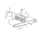
- FIG. 1 a heat resistant polymer fiber layer (B) is attached on the forming sheet take-up device 7.
- the spinning solution of the low-melting polymer prepared by the method described above is metered by the metering pump 1, distributed by the distribution rectifying block 2 so that the pressure and liquid amount are uniform, and sent to the base part 3. It is done.
- a base 4 that is protruded for each hole in a hollow needle shape is attached, and electricity is prevented from leaking to the whole base part 3 by the electrical insulating part 5.
- a plurality of protruding caps 4 made of a conductive material are vertically and vertically attached in parallel to the direction of travel of the forming sheet take-up device 7 made of an endless conveyor. By attaching a terminal to the protruding cap 4, each protruding cap 4 can be applied by a conductive wire.
- a conductive member 8 having a ground is attached to an endless conveyor of the forming sheet take-up device (or a transfer device composed of an endless conveyor) so that the applied potential can be neutralized.
- the spinning dope fed from the base part 3 to the projecting base 4 is charged and split, and then the fiber is continuously drawn from one point of the droplet by the electric field, and a large number of the split fibers are diffused and formed into a semi-dry state.
- a dense and uniform sheet-like low melting point polymer fiber layer is repeatedly formed on the heat resistant polymer fiber layer.
- the laminate of the heat-resistant polymer fiber layer and the low-melting polymer fiber layer that has undergone the electrospinning process is further subjected to a heat-pressure fusion process using embossing or calendering as necessary, so that the adhesion between the laminates (or integral) Property) may be improved.
- the laminate (or battery separator) thus obtained has a total basis weight of, for example, about 5 to 30 g / m 2 , preferably about 6 to 25 g / m 2 , and more preferably about 7 to 20 g / m 2. It may be a range.
- the amount of the low-melting polymer fiber layer is about 0.1 to 10 g / m 2 , preferably about 0.2 to 7 g / m 2. More preferably, it may be in the range of about 0.3 to 6 g / m 2 .
- the heat-resistant polymer fiber layer (B) Since the heat-resistant polymer fiber layer (B) also has a role as a support and requires strong physical properties that can withstand the actual battery production process, the heat-resistant polymer fiber layer (B) has a basis weight of 6 to 20 g. / M 2 is preferable, and about 8 to 18 g / m 2 may be more preferable. If the basis weight is too small, there is a possibility that the strength that can withstand the production process cannot be secured. On the other hand, if the basis weight is too large, the thickness of the substrate becomes too thick and the distance between the electrodes becomes long, so that the battery resistance may increase.
- the ratio (Wb / Wa) of the basis weight (Wb) of the heat-resistant polymer fiber layer to the basis weight (Wa) of the low melting point polymer fiber layer may be about 1 to 5, preferably 1.5 to 4 .5 may be sufficient.
- the measuring method of the said fabric weight it describes in the following examples.
- the thickness of the battery separator may be, for example, about 8 to 40 ⁇ m, preferably about 10 to 30 ⁇ m.
- the measuring method of the said thickness it describes in the following examples.
- the density of the battery separator may be, for example, about 0.3 to 0.8 g / cm 3 , preferably about 0.4 to 0.75 g / cm 3 .
- the average pore size of the whole battery separator may be about 0.05 to 1 ⁇ m, and preferably about 0.1 to 0.8 ⁇ m.
- the said density can be calculated
- the battery separator of the present invention may have a strength of, for example, 0.3 kg / 15 mm or more (eg, about 0.3 to 3 kg / 15 mm) from the viewpoint of handleability, preferably 0.4. It may be about 2 kg / 15 mm.
- a strength of, for example, 0.3 kg / 15 mm or more eg, about 0.3 to 3 kg / 15 mm from the viewpoint of handleability, preferably 0.4. It may be about 2 kg / 15 mm.
- strength it describes in the following examples.
- the liquid absorption amount of the separator may be, for example, 1.5 g / g or more (for example, about 1.5 to 6 g / g), and preferably about 1.8 to 5 g / g. .
- the measuring method of the said liquid absorption amount it describes in the following examples.
- the separator of the present invention having nanofibers in both the low-melting polymer fiber layer and the heat-resistant polymer fiber layer can also improve the fluidity after temporarily holding the electrolytic solution.
- the air permeability may be, for example, about 1 to 600 seconds / 100 cc, and preferably about 30 to 500 seconds / 100 cc.
- the measuring method of the said air permeability it describes in the following examples.
- the battery separator of the present invention is particularly excellent in resistance to hydrogen fluoride generated by thermal decomposition of the electrolyte solution.
- the battery separator is 1 mol% hexafluorophosphoric acid.
- the rate of weight loss after standing at 100 ° C. for 30 minutes in a lithium solution is preferably 2% or less, more preferably 1% or less, and particularly preferably 0%.
- the measuring method of the said weight decreasing rate it describes in the following examples.
- the battery separator of the present invention is compatible with high-power batteries, and the initial resistance value may be, for example, about 0.5 to 10 ⁇ , preferably about 1 to 8 ⁇ .
- the resistance value after heating the separator at the melting point of the low melting point polymer constituting the low melting point polymer fiber layer at + 10 ° C. for 30 minutes is more than twice the initial resistance value before heating ( For example, it may be about 2 to 300 times), preferably about 3 to 200 times, more preferably about 10 to 150 times.
- the measuring method of the said initial resistance value and the resistance value after a heating it describes in detail in the following examples.
- Non-aqueous battery The present invention also includes a non-aqueous battery using the separator.
- the basic structure of the non-aqueous battery includes a positive electrode, a negative electrode, a non-aqueous electrolyte, and a separator, and other members usually used in the technical field of non-aqueous electrolyte batteries as necessary. Is provided.
- the shape of the non-aqueous battery of the present invention is not particularly limited, and can be used as batteries having various shapes such as a coin type, a button type, a paper type, a cylindrical type, and a square type.
- the positive electrode active material of the non-aqueous battery of the present invention is partially different between the primary battery and the secondary battery.
- fluorinated graphite (CF x ), MnO 2 , V 2 Preferable examples include O 5 , SOCl 2 , SO 2 , FeS 2 , CuO, and CuS. These positive electrode active materials may be used alone or in combination of two or more. Of these, fluorinated graphite and MnO 2 are preferable because high energy density is possible and safety is excellent.
- the positive electrode active material of the non-aqueous electrolyte secondary battery metal oxides such as V 2 O 5 and Nb 2 O 5 , Li (1-X) NiO 2 , Li (1-X) MnO 2 , Li Conductive polymers such as (1-X) Mn 2 O 4 , Li (1-X) CoO 2 , lithium-containing composite oxides such as Li (1-X) FeO 2 , and polyanionic lithium fiber metal compounds such as LiFePO 4 Etc.
- X represents a number from 0 to 1.
- Li (1-X) CoO 2 , Li (1-X) NiO 2 , Li (1-X) MnO having a layered structure or a spinel structure 2 is preferable, and LiCoO 2 , LiNiO 2 , and LiMn 2 O 4 are particularly preferable.
- the negative electrode active material of the non-aqueous battery of the present invention is partially different between the primary battery and the secondary battery.
- Examples of the negative electrode active material of the non-aqueous electrolyte primary battery include lithium metal, Mg—Li alloy, Al—Li alloy, etc. Lithium alloys and the like. These negative electrode active materials may be used alone or in combination of two or more.
- the negative electrode active material of the non-aqueous electrolyte secondary battery is a carbon material such as lithium metal, graphite, or amorphous carbon.
- a carbon material such as lithium metal, graphite, or amorphous carbon.
- the carbon material can have a relatively large specific surface area, and the lithium occlusion and release speed is fast, so that it is favorable for charge / discharge characteristics, output and regeneration density at a large current.
- a carbon material is used as the negative electrode active material
- a conductive material and a binder are mixed with the negative electrode active material as necessary to obtain a negative electrode mixture, and this negative electrode mixture is used as a current collector. It is preferable to apply and use.
- the sample weight after immersion for 30 minutes under natural conditions and natural liquid removal for 30 seconds was measured, and the liquid absorption was calculated by dividing the weight of the retained liquid by the sample weight before immersion.
- Example 1 Production of heat-resistant polymer fiber layer (B) 1.7 dtex, 3 mm long solvent-spun cellulose fiber (Cortles, Tencel) was beaten with a pulper and a fiber riser to obtain a CSF 0 ml fibrillated product. This fiber is used as a main fiber, and ethylene-vinyl alcohol fiber (manufactured by Kuraray Co., Ltd., “S030”) is used as a binder fiber in an amount such that the main fiber: binder fiber mass ratio is 80:20. The slurry was adjusted.
- the slurry was made with a round paper machine and dried at a dryer temperature of 130 ° C. to prepare a heat-resistant polymer fiber layer having a basis weight of 10.9 g / m 2 and a thickness of 15 ⁇ m.
- the spinning device a needle having an inner diameter of 0.9 mm was used as the base 4, and the distance between the base 4 and the formed sheet take-up device 7 was 8 cm. Further, the heat-resistant polymer fiber layer obtained in the above (1) was wound around the forming sheet take-up device 7. Next, the conveyor speed is 0.1 m / min, the stock solution is extruded from the die at a predetermined supply amount, a 20 kV applied voltage is applied to the die, and nanofibers having a fiber diameter of 200 nm are applied to the heat-resistant polymer fiber layer at 3.2 g / m 2. Laminated so that
- the laminate of the heat-resistant polymer fiber layer and the low-melting polymer fiber layer obtained in this way was further subjected to a heat press treatment at 170 ° C., and the heat-resistant polymer fiber layer and the low-melting polymer fiber layer were integrated.
- the performance of the obtained separator is shown in Table 1.
- Example 2 A low melting point polymer forming the low melting point polymer fiber layer of Example 1 was produced in the same manner as in Example 1 except that polypropylene was used instead of the ethylene-vinyl alcohol copolymer.
- a polypropylene resin (Grand Polymer Co., Ltd .: B101) is melt kneaded at 300 ° C. with a twin-screw extruder to form a spinning stock solution, and the spinning apparatus shown in FIG. Spinning was performed.
- the spinning device a needle having an inner diameter of 0.3 mm was used as the base 4, and the distance between the base 4 and the formed sheet take-up device 7 was 6 cm. Further, the laminate obtained in (2) of Example 1 was wound around the forming sheet take-up device 7. Next, the conveyor speed is 0.1 m / min, the stock solution is extruded from the die at a predetermined supply rate, and a 40 kV applied voltage is applied to the die to form nanofibers having a fiber diameter of 450 nm on the heat-resistant polymer fiber layer to 3.4 g / m 2 . It laminated
- Example 3 The low melting point polymer fiber layer of Example 2 was prepared in the same manner as in Example 2 except that the low melting point polymer was changed to polyethylene (Mitsui Chemicals: 5202B). The performance of the obtained separator is shown in Table 1.
- Example 4 The low melting point polymer fiber layer of Example 2 was prepared in the same manner as in Example 2 except that the low melting point polymer was changed to polyvinylidene fluoride (manufactured by Arkema Co., Ltd., “KYNAK”). The performance of the obtained separator is shown in Table 1.
- Example 5 Except for changing the low melting point polymer of the low melting point polymer fiber layer of Example 2 to vinylidene fluoride-hexafluoropropylene copolymer (“KYNAK FLEX” manufactured by Arkema Co., Ltd.), the same as in Example 2. Produced. The performance of the obtained separator is shown in Table 1.
- Example 7 The polymer of the heat resistant polymer fiber layer of Example 1 is the same as Example 1 except that the main fiber is an aramid resin (manufactured by Toray DuPont, “Kevlar”, 1.7 dtex, length 3 mm). It was prepared. Specifically, the aramid resin was beaten with a pulper and a fiber riser and used as a fibrillated product of 100 ml of CSF.
- aramid resin manufactured by Toray DuPont, “Kevlar”, 1.7 dtex, length 3 mm. It was prepared. Specifically, the aramid resin was beaten with a pulper and a fiber riser and used as a fibrillated product of 100 ml of CSF.
- Example 8 instead of the heat-resistant polymer fiber layer of Example 1, polyvinyl alcohol fiber (manufactured by Kuraray Co., Ltd., “VPB033 ⁇ 3”) and solvent-spun cellulose fiber prepared in Example 1 (Cortles, Tencel) This was prepared in the same manner as in Example 1 except that it was a mixture with the fibrillated product.
- polyvinyl alcohol fiber manufactured by Kuraray Co., Ltd., “VPB033 ⁇ 3”
- solvent-spun cellulose fiber prepared in Example 1 (Cortles, Tencel) This was prepared in the same manner as in Example 1 except that it was a mixture with the fibrillated product.
- Comparative Example 1 It was produced in the same manner as in Example 1 except that solvent-spun cellulose fiber (Torcel, manufactured by Coatles Co., Ltd.) that had not been beaten was used as the main fiber of the heat-resistant polymer fiber layer.
- the performance of the obtained separator is shown in Table 2.
- Comparative Example 2 It was produced in the same manner as in Example 1 except that the heat resistant polymer fiber layer was omitted. The performance of the obtained separator is shown in Table 2.
- Example 4 A low-melting polymer fiber layer was produced in the same manner as in Example 1 except that non-nanofibers having a fiber diameter of 1200 nm were formed by an electrostatic spinning method. The performance of the obtained separator is shown in Table 2.
- This sheet was set in a biaxial stretching machine, and simultaneously biaxially stretched 7 ⁇ 7 times at 115 ° C., and liquid paraffin was extracted with methyl ethyl ketone to obtain a polyethylene microporous film.
- the performance of the obtained microporous film is shown in Table 2.
- the separators of Examples 1 to 8 all have low initial resistance, they exhibit excellent properties as high-power non-aqueous battery separators. Furthermore, in these examples, since the polymer of the low melting point polymer fiber layer can be melted by abnormal heat generation to form a film, it also shows good shutdown characteristics. Furthermore, the strength of the separator is high, and the handleability during manufacture is also excellent. Furthermore, the resistance to hydrogen fluoride is high, and the weight of the separator does not change at all against hydrogen fluoride (HF) generated by the decomposition of the electrolytic solution.
- HF hydrogen fluoride
- the separator of Comparative Example 1 since the separator of Comparative Example 1 does not have nanofibers in the heat-resistant polymer fiber layer, the polymer of the low-melting-point polymer fiber layer becomes void in the heat-resistant polymer fiber layer (B) layer when melted with abnormal heat generation. It cannot be used as a separator for a non-aqueous battery in which a film cannot be formed efficiently, a film cannot be formed efficiently, shutdown characteristics are insufficient, and safety is essential.
- the separator of Comparative Example 2 Since the separator of Comparative Example 2 has low strength and is likely to be damaged, the processability is poor and it cannot be used as a separator for non-aqueous batteries. Moreover, in the separator of the comparative example 3 which does not contain a low melting-point polymer fiber layer, and the separator of the comparative example 4 whose low-melting-point polymer fiber layer does not contain nanofiber, a short circuit will generate
- the microporous film of Comparative Example 5 Since the microporous film of Comparative Example 5 has a high initial resistance, the internal resistance of the battery becomes high when used as a separator for a non-aqueous battery, and not only a high output cannot be obtained, but also has a shutdown characteristic due to melting, but is abnormal. Since the sheet form is not maintained when the heat generation proceeds and the temperature becomes higher, the pole materials may come into contact with each other to further increase the danger, which is insufficient as a safety function.
- the separator for non-aqueous batteries of the present invention can be usefully used for non-aqueous batteries.
Abstract
Description
本発明の別の目的は、電池が異常に加熱した場合、速やかに溶融膜を形成してシャットダウン特性を発揮できるだけでなく、耐電解液性をも有する非水系電池用セパレータを提供することにある。
本発明のさらに別の目的は、ナノファイバー層との一体性に優れ、電池を製造する工程での取り扱い性に優れる非水系電池用セパレータを提供することにある。
本発明のさらに他の目的は、高出力であるとともに安全性にも優れている非水系電池を提供することにある。
融点が100~200℃の低融点ポリマーで構成された低融点ポリマーファイバー層(A)と、
この低融点ポリマーファイバー層(A)の上に形成され、融点が200℃を超える高融点ポリマーもしくは熱不融性ポリマーで構成された耐熱性ポリマーファイバー層(B)とを備えた積層体で構成され、
前記低融点ポリマーファイバー層(A)は、前記低融点ポリマーから形成され、繊維径が1000nm以下のナノファイバーを含み、
前記耐熱性ポリマーファイバー層(B)は、前記耐熱性ポリマーから形成され、繊維径が1000nm以下のナノファイバーと、繊維径が1000nmを超える非ナノファイバーとの混合物を含む非水系電池用セパレータである。
融点が200℃を超える高融点ポリマーまたは熱不融性ポリマーで構成された耐熱性ポリマーから、繊維径が1000nm以下のナノファイバーと、繊維径が1000nmを超える非ナノファイバーとをそれぞれ調製して、双方の繊維を含む繊維集合体で構成された耐熱性ポリマーファイバー層を形成する耐熱性ポリマーファイバー層形成工程と、
融点が100~200℃の低融点ポリマーから形成され、繊維径が1000nm以下のナノファイバーを調製して、低融点ポリマーファイバー層を形成する低融点ポリマーファイバー層形成工程と、
前記低融点ポリマーファイバー層と、前記耐熱性ポリマーファイバー層とを積層する積層工程と、
を含んでいる。
融点が200℃を超える高融点ポリマーまたは熱不融性ポリマーで構成された耐熱性ポリマーから、繊維径が1000nm以下のナノファイバーと、繊維径が1000nmを超える非ナノファイバーをそれぞれ調製して、双方を含む繊維集合体で構成された耐熱性ポリマーファイバー層を形成する耐熱性ポリマーファイバー層形成工程と、
融点が100~200℃の低融点ポリマーを溶解することが可能な溶媒に前記ポリマーを溶解して得られた溶解液を、および/または低融点ポリマーを溶融して得られた溶融液を、紡糸原液として調製する紡糸原液調製工程と、
前記紡糸原液を用いて静電紡糸法によりナノファイバーを前記耐熱性ポリマーファイバー層に積層して複合する静電紡糸工程と、
を含んでいる。
低融点ポリマーファイバー層は、融点100~200℃の低融点ポリマーを含むことが重要である。低融点ポリマーファイバー層が融点100~200℃のポリマーを含むことにより、異常電流や、リチウムデンドライドによる内部短絡によって電池の温度上昇が生じた場合であっても、低融点ポリマーファイバー層が溶融して皮膜を形成して抵抗を高め、シャットダウン特性を与えることができる。
エチレン-ビニルアルコール共重合体は、エチレン/酢酸ビニル系共重合体の酢酸ビニル部分をケン化することにより得ることができ、ケン化度としては、例えば、約95モル%以上、好ましくは98モル%以上、より好ましくは99モル%以上100モル%以下であってもよい。
耐熱性ポリマーファイバー層は、低融点ポリマーファイバー層が皮膜を形成する際の支持体として機能し、セパレータ全体の形状を保持する観点から、融点が200℃を超える高融点ポリマーおよび熱不融性ポリマーからなる群から選択された少なくとも一種の耐熱性ポリマーを含むことが必要である。
また、セパレータを形成する低融点ポリマーと高融点ポリマーとの融点の差は、例えば、50~200℃程度、好ましくは60~180℃程度であってもよい。
次に本発明を構成するセパレータの製造方法について説明する。本発明のセパレータの製造方法は、低融点ナノファイバーの形成方法に応じて適宜設定することが可能であり、融点が200℃を超える高融点ポリマーもしくは熱不融性ポリマーで構成された耐熱性ポリマーから、繊維径が1000nm以下のナノファイバーと、繊維径が1000nmを超える非ナノファイバーを調製して、耐熱性ポリマーファイバー層を形成する耐熱性ポリマーファイバー層形成工程と、融点が100~200℃の低融点ポリマーから形成され、繊維径が1000nm以下のナノファイバーを調製して、低融点ポリマーファイバー層を形成する低融点ポリマーファイバー層形成工程と、前記低融点ポリマーファイバー層と、前記耐熱性ポリマーファイバー層とを積層する積層工程と、を少なくとも含んでいる。
静電紡糸の方法としては特に制限はなく、紡糸原液を供給できる導電性部材に高電圧を印加することで、接地した対極側にナノファイバーを堆積させる方法をとる。これにより、原液供給部から吐出された紡糸原液が帯電分裂され、ついで電場により液滴の一点からファイバーが連続的に引き出され、分割された繊維が多数拡散する。ポリマーの濃度が10%以下であっても、溶媒は繊維形成と細化の段階で乾燥しやすく、原液供給部より数cm~数十cm離れた設置された捕集ベルトあるいはシートに堆積する。堆積と共に半乾燥繊維は微膠着し、繊維間の移動を防止し、新たな微細繊維が逐次堆積し、緻密なシート状のナノファイバー層が得られる。
第1図において、形成シート引取り装置7の上には、耐熱性ポリマーファイバー層(B)が取り付けられている。また、前記に記載した方法で調製された低融点ポリマーの紡糸原液は、定量ポンプ1により計量送液され、分配整流ブロック2により均一な圧力と液量となるように分配され口金部3に送られる。
このようにして得られた積層体(または電池用セパレータ)は、総目付が、例えば5~30g/m2程度、好ましくは6~25g/m2程度、さらに好ましくは7~20g/m2程度の範囲であってもよい。
本発明は、前記セパレータを用いた非水系電池も包含する。非水系電池の基本的な構造は、正極と、負極と、非水電解液と、セパレータとを備え、その他、必要に応じて非水電解液電池の技術分野で通常使用されている他の部材を備える。本発明の非水系電池は、その形状には特に制限されず、コイン型、ボタン型、ペーパー型、円筒型、角型等、種々の形状の電池として使用できる。
低融点ポリマーファイバー層において、顕微鏡により倍率5000倍で撮影した不織布構成繊維の断面の拡大写真から、無作為に100本の繊維を選び、それらの繊維径を測定し、その平均値を平均繊維径とした。
耐熱性ポリマーファイバー層において、顕微鏡により倍率5000倍で撮影した不織布構成繊維の断面の拡大写真から、無作為に100本の繊維を選び、それらの繊維径を測定し、最も大きい値を最大繊維径、最も小さい値を最小繊維径とした。
試料50mgを示差走査熱量計(セイコーインスツル(株)製:DSC6200)により測定し吸熱ピーク値を融点とした。
JIS P 8124「紙のメートル坪量測定方法」に準じて測定した。
JIS P 8118「紙及び板紙の厚さと密度の試験方法」に準じて測定した。
JIS P 8113「紙及び板紙の引張特性の試験方法」に準じて測定した。
50mm×50mmの試料を6フッ化リン酸リチウム液(キシダ化学(株):1mol/l LiPF6/EC:EMC=3:7(v/v%);23℃)に浴比1/100の条件で30分浸漬し、30秒間自然液切りした後の試料重量を測定し、保液された液体の重量を浸漬前の試料重量で除することによって吸液量を算出した。
JIS P 8117に準じ、ガーレ式透気度試験器を用いて測定した。
PMI社製;Perm-Porometerにより測定した。
予め秤量した試料サンプル(5×5cm)に対して、1mol%の6フッ化リン酸リチウム液(キシダ化学(株):1mol/l LiPF6/EC:EMC (3:7v/v%))を加え、100℃で30分放置した後、試料サンプルを取り出し、水洗、乾燥した試料サンプルの重量を測定し、6フッ化リン酸リチウム液へ浸漬する前後の試料サンプルの重量減少率(%)を求めた。
試料を、1mol%の6フッ化リン酸リチウム液(キシダ化学(株):1mol/l LiPF6/EC:EMC (3:7v/v%))に20℃、30分浸漬し、保液十分な状態(30秒液切りした状態)で、測定雰囲気(20℃×65%RH)にてインピーダンス測定器(国洋電気工業(株)製:KC-547 LCR METER)で測定した。
抵抗値が10Ω以下の試料ならば低抵抗となり、高出力の非水系電池が作製可能なことから○と判定した。それ以上は抵抗が高すぎ、非水系電池として劣ったものとなってしまうため×と判定した。
ステンレス製密閉容器内に電解液と試料を投入し、オイルバス中で低融点ポリマーファイバー層を構成する低融点ポリマーの融点+10℃で30分加熱し、加熱後の試料を、1mol%の6フッ化リン酸リチウム液(キシダ化学(株):1mol/l LiPF6/EC:EMC (3:7v/v%))に20℃、30分浸漬し、保液十分な状態(30秒液切りした状態)で、測定雰囲気(20℃×65%RH)にてインピーダンス測定器(国洋電気工業(株)製:KC-547 LCR METER)で測定した。
200℃以下で初期抵抗値が2倍以上に向上しているサンプルをシャットダウン特性が発現している○と判定し、それ以下を×とした。
(1)耐熱性ポリマーファイバー層(B)の製造
1.7dtex、長さ3mmの溶剤紡糸セルロース繊維(コートールズ社製、テンセル)をパルパーとファイバライザーにて叩解し、CSF0mlのフイブリル化物とした。この繊維を主体繊維とし、エチレン-ビニルアルコール系繊維((株)クラレ製、「S030」)をバインダー繊維として、主体繊維:バインダー繊維の質量比が80:20となるような量で添加してスラリーを調整した。
まずエチレン-ビニルアルコール共重合体(EVOH:(株)クラレ製,EVAL-G)を14質量%となるようにDMSO溶媒に投入後、25℃で静置溶解し、紡糸原液を得た。得られた紡糸原液を用い、図1の紡糸装置にて静電紡糸を行った。
実施例1の低融点ポリマーファイバー層を形成する低融点ポリマーを、エチレン-ビニルアルコール共重合体に代えて、ポリプロピレンとする以外は、実施例1と同様に作製した。
実施例2の低融点ポリマーファイバー層の低融点ポリマーを、ポリエチレン(三井化学製:5202B)に変更すること以外は、実施例2と同様に作製した。得られたセパレータの性能を表1に示す。
実施例2の低融点ポリマーファイバー層の低融点ポリマーを、ポリフッ化ビニリデン(アルケマ(株)製、「KYNAK」)に変更すること以外は、実施例2と同様に作製した。得られたセパレータの性能を表1に示す。
実施例2の低融点ポリマーファイバー層の低融点ポリマーを、フッ化ビニリデン-ヘキサフルオロプロピレン共重合体(アルケマ(株)製、「KYNAK FLEX」)に変更すること以外は、実施例2と同様に作製した。得られたセパレータの性能を表1に示す。
実施例2の低融点ポリマーファイバー層の低融点ポリマーを、ポリフッ化ビニリデン(PVDF:アルケマ(株)製、「KYNAK」)とエチレン-ビニルアルコール共重合体(EVOH:(株)クラレ製、「EVAL-G」)とのブレンド物(質量比:PVDF/EVOH=30/70)に変更すること以外は、実施例2と同様に作製した。得られたセパレータの性能を表1に示す。
実施例1の耐熱性ポリマーファイバー層のポリマーとして、主体繊維をアラミド樹脂(東レ・デュポン(株)製、「ケブラー」、1.7dtex、長さ3mm)とすること以外は、実施例1と同様に作製した。具体的には、アラミド樹脂は、パルパーとファイバライザーにて叩解し、CSF100mlのフイブリル化物として用いた。
実施例1の耐熱性ポリマーファイバー層に代えて、主体繊維をポリビニルアルコール繊維((株)クラレ製、「VPB033×3」)と、実施例1で作製した溶剤紡糸セルロース繊維(コートールズ社製、テンセル)のフィブリル化物との混合物とすること以外は、実施例1と同様に作製した。
耐熱性ポリマーファイバー層の主体繊維として、叩解処理を施していない溶剤紡糸セルロース繊維(コートールズ社製、テンセル)を用いる以外は、実施例1と同様に作製した。得られたセパレータの性能を表2に示す。
耐熱性ポリマーファイバー層を省略すること以外は実施例1と同様に作製した。得られたセパレータの性能を表2に示す。
低融点ポリマーファイバー層を省略すること以外は実施例1と同様に作製した。得られたセパレータの性能を表2に示す。
低融点ポリマーファイバー層として、繊維径が1200nmの非ナノファイバーを静電紡糸法によって形成する以外は、実施例1と同様にして作製した。得られたセパレータの性能を表2に示す。
二軸押出機にポリエチレン(三井化学(株)製:5202B)100質量部を供給し、流動パラフィン120質量部を二軸押出機のシリンダーに設けた注入口から注入して220℃で十分に溶融混練を行うことによりポリエチレン溶液を調製し、二軸押出機の先端に取り付けたTダイからポリエチレン溶液をシート状に押し出し冷却した。このシートを二軸延伸機にセットし、115℃で7×7倍に同時二軸延伸を行い、メチルエチルケトンで流動パラフィンを抽出してポリエチレン微多孔フィルムを得た。得られた微多孔フィルムの性能を表2に示す。
特公昭52-151624号公報に記載の方法で調製したアラミドファイブリッドを離解機、叩解機で処理して得られた重量平均繊維長0.9mmのアラミドファイブリッドパルプ状物5重量部と、アラミド短繊維(デュポン社製メタアラミド繊維:繊維長6mm)49重量部とを水中で分散しスラリーを作製した。このスラリーを、タッピー式手抄き機(断面積325cm2)にてシート状物を作製した。次いで、これを金属製カレンダーロールにより温度295℃、線圧300kg/cmで熱圧加工し、アラミド薄葉材を得た。
このアラミド薄葉材に対して、比較例5で作製したポリエチレン製多孔質フィルムを貼り合わせ、セパレータを作製した。得られたセパレータの性能を表2に示す。

また、低融点ポリマーファイバー層を含まない比較例3のセパレータや、低融点ポリマーファイバー層がナノファイバーを含まない比較例4のセパレータでは、セパレータ内部で短絡を発生してしまう。
Claims (14)
- 融点が100~200℃の低融点ポリマーで構成された低融点ポリマーファイバー層(A)と、
この低融点ポリマーファイバー層(A)の上に形成され、融点が200℃を超える高融点ポリマーもしくは熱不融性ポリマーで構成された耐熱性ポリマーファイバー層(B)とを備えた積層体で構成され、
前記低融点ポリマーファイバー層(A)は、前記低融点ポリマーから形成され、繊維径が1000nm以下のナノファイバーを含み、
前記耐熱性ポリマーファイバー層(B)は、前記耐熱性ポリマーから形成され、繊維径が1000nm以下のナノファイバーと、繊維径が1000nmを超える非ナノファイバーとの混合物を含む非水系電池用セパレータ。 - 請求項1のセパレータにおいて、低融点ポリマーファイバー層(A)を構成するポリマーが、ポリオレフィン系ポリマー、エチレン-ビニルアルコール系共重合物、およびフッ素系ポリマーからなる群から選択された少なくとも一種で構成されている非水系電池用セパレータ。
- 請求項1または2のセパレータにおいて、耐熱性ポリマーファイバー層(B)を構成するポリマーが、全芳香族ポリアミド系ポリマー、ポリビニルアルコール系ポリマー、およびセルロース系ポリマーからなる群から選択された少なくとも一種で構成されている非水系電池用セパレータ。
- 請求項1から3のいずれか一項のセパレータにおいて、低融点ポリマーファイバー層(A)に含まれるナノファイバーの平均繊維径が10~800nmである非水系電池用セパレータ。
- 請求項1から4のいずれか一項のセパレータにおいて、耐熱性ポリマーファイバー層(B)が、叩解度0~300mlの耐熱性ポリマー繊維を主体繊維として含む湿式不織布である非水系電池用セパレータ。
- 請求項1から5のいずれか一項のセパレータにおいて、低融点ポリマーファイバー層(A)の目付(Wa)に対する耐熱性ポリマーファイバー層(B)の目付(Wb)が、(Wb)/(Wa)=1~5である非水系電池用セパレータ。
- 請求項1から6のいずれか一項のセパレータにおいて、低融点ポリマーファイバー層(A)の目付(Wa)が1~10g/m2であり、耐熱性ポリマーファイバー層(B)の目付(Wb)が6~20g/m2である非水系電池用セパレータ。
- 請求項1から7のいずれか一項のセパレータにおいて、積層体の厚さが10~30μmである非水系電池用セパレータ。
- 請求項1から8のいずれか一項のセパレータにおいて、初期抵抗値が0.5~10Ωであり、且つ低融点ポリマーファイバー層(A)を構成する低融点ポリマーの融点+10℃で、30分加熱した後の抵抗値が、加熱前の初期抵抗値の3倍以上である非水系電池用セパレータ。
- 請求項1から9のいずれか一項のセパレータにおいて、低融点ポリマーファイバー層(A)が、静電紡糸法により形成されている非水系電池用セパレータ。
- 融点が200℃を超える高融点ポリマーまたは熱不融性ポリマーで構成された耐熱性ポリマーから、繊維径が1000nm以下のナノファイバーと、繊維径が1000nmを超える非ナノファイバーとをそれぞれ調製して、双方の繊維を含む繊維集合体で構成された耐熱性ポリマーファイバー層を形成する耐熱性ポリマーファイバー層形成工程と、
融点が100~200℃の低融点ポリマーから形成され、繊維径が1000nm以下のナノファイバーを調製して、低融点ポリマーファイバー層を形成する低融点ポリマーファイバー層形成工程と、
前記低融点ポリマーファイバー層と、前記耐熱性ポリマーファイバー層とを積層する積層工程と、
を含む請求項1~10のいずれか一項に記載の非水系電池用セパレータの製造方法。 - 融点が200℃を超える高融点ポリマーまたは熱不融性ポリマーで構成された耐熱性ポリマーから、繊維径が1000nm以下のナノファイバーと、繊維径が1000nmを超える非ナノファイバーをそれぞれ調製して、双方を含む繊維集合体で構成された耐熱性ポリマーファイバー層を形成する耐熱性ポリマーファイバー層形成工程と、
融点が100~200℃の低融点ポリマーを溶解することが可能な溶媒に前記ポリマーを溶解して得られた溶解液を、および/または低融点ポリマーを溶融して得られた溶融液を、紡糸原液として調製する紡糸原液調製工程と、
前記紡糸原液を用いて静電紡糸法によりナノファイバーを前記耐熱性ポリマーファイバー層に積層して複合する静電紡糸工程と、
を含む請求項1~10のいずれか一項に記載の非水系電池用セパレータの製造方法。 - 請求項11または12の製造方法において、耐熱性ポリマーファイバー層が、耐熱性ポリマー繊維を叩解して得られた繊維を主体繊維として含む製造方法。
- 請求項1~10のいずれか一項に記載の非水系電池用セパレータを使用した非水系電池。
Priority Applications (5)
| Application Number | Priority Date | Filing Date | Title |
|---|---|---|---|
| CN201080041219.6A CN102498592B (zh) | 2009-09-16 | 2010-09-08 | 非水类电池用隔板及使用其的非水类电池以及非水类电池用隔板的制造方法 |
| KR1020127008640A KR101714811B1 (ko) | 2009-09-16 | 2010-09-08 | 비수계 전지용 세퍼레이터 및 그것을 사용한 비수계 전지, 그리고 비수계 전지용 세퍼레이터의 제조 방법 |
| EP10817088.7A EP2479820B1 (en) | 2009-09-16 | 2010-09-08 | Separator for non-aqueous batteries, non-aqueous battery using same, and production method for separator for non-aqueous batteries |
| JP2011531897A JP5529148B2 (ja) | 2009-09-16 | 2010-09-08 | 非水系電池用セパレータ及びそれを用いた非水系電池、ならびに非水系電池用セパレータの製造方法 |
| US13/414,030 US8802271B2 (en) | 2009-09-16 | 2012-03-07 | Separator for non-aqueous batteries, non-aqueous battery using same, and production method for separator for non-aqueous batteries |
Applications Claiming Priority (2)
| Application Number | Priority Date | Filing Date | Title |
|---|---|---|---|
| JP2009-214216 | 2009-09-16 | ||
| JP2009214216 | 2009-09-16 |
Related Child Applications (1)
| Application Number | Title | Priority Date | Filing Date |
|---|---|---|---|
| US13/414,030 Continuation US8802271B2 (en) | 2009-09-16 | 2012-03-07 | Separator for non-aqueous batteries, non-aqueous battery using same, and production method for separator for non-aqueous batteries |
Publications (1)
| Publication Number | Publication Date |
|---|---|
| WO2011033975A1 true WO2011033975A1 (ja) | 2011-03-24 |
Family
ID=43758583
Family Applications (1)
| Application Number | Title | Priority Date | Filing Date |
|---|---|---|---|
| PCT/JP2010/065402 WO2011033975A1 (ja) | 2009-09-16 | 2010-09-08 | 非水系電池用セパレータ及びそれを用いた非水系電池、ならびに非水系電池用セパレータの製造方法 |
Country Status (6)
| Country | Link |
|---|---|
| US (1) | US8802271B2 (ja) |
| EP (1) | EP2479820B1 (ja) |
| JP (1) | JP5529148B2 (ja) |
| KR (1) | KR101714811B1 (ja) |
| CN (1) | CN102498592B (ja) |
| WO (1) | WO2011033975A1 (ja) |
Cited By (22)
| Publication number | Priority date | Publication date | Assignee | Title |
|---|---|---|---|---|
| JP2012209235A (ja) * | 2011-03-28 | 2012-10-25 | Samsung Electro-Mechanics Co Ltd | 二次電池繊維状分離膜およびその製造方法 |
| JP2012209234A (ja) * | 2011-03-28 | 2012-10-25 | Samsung Electro-Mechanics Co Ltd | 二次電池繊維状分離膜およびその製造方法 |
| US20120295165A1 (en) * | 2011-05-20 | 2012-11-22 | Morin Brian G | Single-layer lithium ion battery separator |
| JP2012232518A (ja) * | 2011-05-02 | 2012-11-29 | Daicel Corp | 不織繊維積層体及びその製造方法並びにセパレータ |
| WO2013065290A1 (ja) * | 2011-10-31 | 2013-05-10 | パナソニック株式会社 | リチウム一次電池およびその製造方法 |
| JP2013534980A (ja) * | 2010-06-21 | 2013-09-09 | コーロン インダストリーズ インク | 多孔性ナノウェブ及びその製造方法 |
| WO2013180073A1 (ja) | 2012-05-28 | 2013-12-05 | 株式会社クラレ | 非水系電池用セパレータ及び非水系電池 |
| CN103437071A (zh) * | 2013-09-11 | 2013-12-11 | 浙江伟星实业发展股份有限公司 | 一种静电纺纳米纤维膜及其制备方法 |
| JP2013251347A (ja) * | 2012-05-30 | 2013-12-12 | Panasonic Corp | キャパシタ、キャパシタ用セパレータおよびキャパシタ用セパレータの製造方法 |
| CN103620818A (zh) * | 2011-06-28 | 2014-03-05 | 日产自动车株式会社 | 带耐热绝缘层的隔板 |
| US20140205908A1 (en) * | 2013-01-21 | 2014-07-24 | Samsung Sdi Co., Ltd. | Enhanced-safety galvanic element |
| US20140213135A1 (en) * | 2011-09-28 | 2014-07-31 | Kuraray Co., Ltd. | Extra-fine fiber sheet |
| US20140272599A1 (en) * | 2013-03-15 | 2014-09-18 | Brian G. Morin | Direct Electrolyte Gelling Via Battery Separator Composition and Structure |
| CN104727016A (zh) * | 2014-04-01 | 2015-06-24 | 浙江伟星实业发展股份有限公司 | 一种纳米纤维复合膜及其制备方法 |
| US20150372273A1 (en) * | 2013-02-06 | 2015-12-24 | Toptec Hns Co., Ltd. | Hybrid nonwoven separator having inverted structure |
| JP2016502736A (ja) * | 2012-11-14 | 2016-01-28 | ジー. モリン,ブライアン | 低収縮性単層リチウムイオンバッテリセパレータ |
| JP2016506017A (ja) * | 2012-11-20 | 2016-02-25 | ジー. モリン,ブライアン | ナノファイバとマイクロファイバ構成要素を有する単層リチウムイオンバッテリセパレータの作製方法 |
| JP2016532014A (ja) * | 2013-07-15 | 2016-10-13 | ソルヴェイ(ソシエテ アノニム) | フルオロポリマー繊維 |
| JP2017053075A (ja) * | 2011-10-13 | 2017-03-16 | 大王製紙株式会社 | 多孔性を有する3層積層シート及びその製造方法、並びに3層積層シートからなる蓄電素子用セパレータ |
| US10020124B2 (en) | 2012-12-26 | 2018-07-10 | Kuraray Co., Ltd. | Separator for electric double layer capacitors, and electric double layer capacitor |
| WO2019163933A1 (ja) * | 2018-02-26 | 2019-08-29 | 株式会社ダイセル | 二次電池用セパレータ |
| JP2019149361A (ja) * | 2018-02-26 | 2019-09-05 | 株式会社ダイセル | 二次電池用セパレータ |
Families Citing this family (13)
| Publication number | Priority date | Publication date | Assignee | Title |
|---|---|---|---|---|
| US8361365B2 (en) * | 2006-12-20 | 2013-01-29 | E I Du Pont De Nemours And Company | Process for electroblowing a multiple layered sheet |
| AT512460B1 (de) * | 2011-11-09 | 2013-11-15 | Chemiefaser Lenzing Ag | Dispergierbare nicht-gewebte Textilien |
| CN102832367B (zh) * | 2012-08-31 | 2014-12-31 | 浙江大东南包装股份有限公司 | 一种锂离子二次电池隔膜及其制备方法 |
| US9637861B1 (en) * | 2012-11-20 | 2017-05-02 | Dreamweaver International, Inc. | Methods of making single-layer lithium ion battery separators having nanofiber and microfiber constituents |
| US20140141337A1 (en) * | 2012-11-20 | 2014-05-22 | Brian G. Morin | Versatile Single-Layer Lithium Ion Battery Separators Having Nanofiber and Microfiber Components |
| CN103840111B (zh) * | 2012-11-27 | 2016-03-09 | 比亚迪股份有限公司 | 聚合物膜、凝胶聚合物电解质和聚合物锂电池及其制备方法 |
| WO2014113944A1 (zh) * | 2013-01-23 | 2014-07-31 | 华南理工大学 | 一种隔膜纸及其制备方法和应用 |
| KR101267283B1 (ko) * | 2013-01-25 | 2013-05-27 | 톱텍에이치앤에스 주식회사 | 전해액 젖음성이 우수한 이차전지용 분리막 및 이의 제조방법 |
| CN103541149B (zh) * | 2013-08-29 | 2017-04-05 | 天津工业大学 | 一种增强静电纺纳米纤维膜的方法 |
| CN105723030B (zh) * | 2013-09-06 | 2018-06-05 | 帝人芳纶有限公司 | 用于电化学电池的隔纸 |
| WO2015069008A1 (ko) * | 2013-11-05 | 2015-05-14 | 주식회사 엘지화학 | 전기화학소자용 분리막 |
| CN104485437B (zh) * | 2014-12-19 | 2018-02-09 | 宁波艾特米克锂电科技有限公司 | 具有热闭孔功能复合纳米纤维隔膜、制备方法和储能器件 |
| CN108711604B (zh) * | 2018-05-28 | 2022-01-25 | 河南科高辐射化工科技有限公司 | 一种高温闭孔自封闭型锂电池隔膜的制备方法 |
Citations (7)
| Publication number | Priority date | Publication date | Assignee | Title |
|---|---|---|---|---|
| JPS52151624A (en) | 1976-06-14 | 1977-12-16 | Mitsubishi Keikinzoku Kogyo | Method of electromagnetically casting aluminium alloy |
| JPS61232560A (ja) * | 1985-04-08 | 1986-10-16 | Fuji Elelctrochem Co Ltd | リチウム電池 |
| JPH08306352A (ja) | 1995-05-10 | 1996-11-22 | Nippon Koudoshi Kogyo Kk | 非水系電池 |
| JP2002170540A (ja) * | 2000-11-30 | 2002-06-14 | Tonen Tapyrus Co Ltd | セパレータ |
| JP2006092829A (ja) | 2004-09-22 | 2006-04-06 | Teijin Ltd | リチウムイオン二次電池用セパレータおよびその製造方法とリチウムイオン二次電池 |
| JP2009214216A (ja) | 2008-03-10 | 2009-09-24 | Konica Minolta Business Technologies Inc | 紙断裁装置 |
| JP2010103050A (ja) * | 2008-10-27 | 2010-05-06 | Kuraray Co Ltd | リチウム電池用セパレータ及びそれを用いたリチウム電池 |
Family Cites Families (8)
| Publication number | Priority date | Publication date | Assignee | Title |
|---|---|---|---|---|
| US6753114B2 (en) * | 1998-04-20 | 2004-06-22 | Electrovaya Inc. | Composite electrolyte for a rechargeable lithium battery |
| US6730439B2 (en) | 2000-08-01 | 2004-05-04 | Tonen Tapyrus Co., Ltd. | Heat-resistant separator |
| JP4593566B2 (ja) * | 2003-06-17 | 2010-12-08 | ナノフィル カンパニー リミテッド | 電気化学素子用複合膜、その製造方法及びこれを備えた電気化学素子 |
| US8092566B2 (en) * | 2004-12-28 | 2012-01-10 | E.I. Du Pont De Nemours And Company | Filtration media for filtering particulate material from gas streams |
| JP4992186B2 (ja) * | 2005-03-02 | 2012-08-08 | 東レ株式会社 | 電池セパレータ |
| DE102006021273A1 (de) * | 2006-05-05 | 2007-11-08 | Carl Freudenberg Kg | Separator zur Anordnung in Batterien und Batterie |
| US8865336B2 (en) | 2006-12-20 | 2014-10-21 | Kuraray Co., Ltd. | Separator for alkaline battery, method for producing the same, and battery |
| CN101821824B (zh) * | 2007-10-18 | 2012-07-04 | 株式会社可乐丽 | 层叠体、电容器用隔板和电容器 |
-
2010
- 2010-09-08 JP JP2011531897A patent/JP5529148B2/ja not_active Expired - Fee Related
- 2010-09-08 KR KR1020127008640A patent/KR101714811B1/ko active IP Right Grant
- 2010-09-08 EP EP10817088.7A patent/EP2479820B1/en not_active Not-in-force
- 2010-09-08 WO PCT/JP2010/065402 patent/WO2011033975A1/ja active Application Filing
- 2010-09-08 CN CN201080041219.6A patent/CN102498592B/zh not_active Expired - Fee Related
-
2012
- 2012-03-07 US US13/414,030 patent/US8802271B2/en not_active Expired - Fee Related
Patent Citations (7)
| Publication number | Priority date | Publication date | Assignee | Title |
|---|---|---|---|---|
| JPS52151624A (en) | 1976-06-14 | 1977-12-16 | Mitsubishi Keikinzoku Kogyo | Method of electromagnetically casting aluminium alloy |
| JPS61232560A (ja) * | 1985-04-08 | 1986-10-16 | Fuji Elelctrochem Co Ltd | リチウム電池 |
| JPH08306352A (ja) | 1995-05-10 | 1996-11-22 | Nippon Koudoshi Kogyo Kk | 非水系電池 |
| JP2002170540A (ja) * | 2000-11-30 | 2002-06-14 | Tonen Tapyrus Co Ltd | セパレータ |
| JP2006092829A (ja) | 2004-09-22 | 2006-04-06 | Teijin Ltd | リチウムイオン二次電池用セパレータおよびその製造方法とリチウムイオン二次電池 |
| JP2009214216A (ja) | 2008-03-10 | 2009-09-24 | Konica Minolta Business Technologies Inc | 紙断裁装置 |
| JP2010103050A (ja) * | 2008-10-27 | 2010-05-06 | Kuraray Co Ltd | リチウム電池用セパレータ及びそれを用いたリチウム電池 |
Non-Patent Citations (1)
| Title |
|---|
| See also references of EP2479820A4 |
Cited By (34)
| Publication number | Priority date | Publication date | Assignee | Title |
|---|---|---|---|---|
| JP2013534980A (ja) * | 2010-06-21 | 2013-09-09 | コーロン インダストリーズ インク | 多孔性ナノウェブ及びその製造方法 |
| US9142815B2 (en) | 2010-06-21 | 2015-09-22 | Kolon Industries, Inc. | Method for manufacturing a porous nanoweb |
| JP2012209235A (ja) * | 2011-03-28 | 2012-10-25 | Samsung Electro-Mechanics Co Ltd | 二次電池繊維状分離膜およびその製造方法 |
| US8968909B2 (en) | 2011-03-28 | 2015-03-03 | Samsung Electro-Mechanics Co., Ltd | Fibrous separation membrane for secondary battery and manufacturing method thereof |
| JP2012209234A (ja) * | 2011-03-28 | 2012-10-25 | Samsung Electro-Mechanics Co Ltd | 二次電池繊維状分離膜およびその製造方法 |
| JP2012232518A (ja) * | 2011-05-02 | 2012-11-29 | Daicel Corp | 不織繊維積層体及びその製造方法並びにセパレータ |
| US20120295165A1 (en) * | 2011-05-20 | 2012-11-22 | Morin Brian G | Single-layer lithium ion battery separator |
| US11171387B2 (en) * | 2011-05-20 | 2021-11-09 | Dreamweaves Intl., Inc. | Single-layer lithium ion battery separator |
| US9666848B2 (en) * | 2011-05-20 | 2017-05-30 | Dreamweaver International, Inc. | Single-layer lithium ion battery separator |
| CN103688387A (zh) * | 2011-05-20 | 2014-03-26 | 梦想编织者国际股份有限公司 | 单层锂离子电池隔膜 |
| US20130078525A1 (en) * | 2011-05-20 | 2013-03-28 | James L. Schaeffer | Single-Layer Lithium Ion Battery Separator |
| CN103620818A (zh) * | 2011-06-28 | 2014-03-05 | 日产自动车株式会社 | 带耐热绝缘层的隔板 |
| US9728757B2 (en) | 2011-06-28 | 2017-08-08 | Nissan Motor Co., Ltd. | Separator having heat-resistant insulating layer and electric device comprising the same |
| US20140213135A1 (en) * | 2011-09-28 | 2014-07-31 | Kuraray Co., Ltd. | Extra-fine fiber sheet |
| US10106923B2 (en) * | 2011-09-28 | 2018-10-23 | Kuraray Co., Ltd. | Extra-fine fiber sheet |
| JP2017053075A (ja) * | 2011-10-13 | 2017-03-16 | 大王製紙株式会社 | 多孔性を有する3層積層シート及びその製造方法、並びに3層積層シートからなる蓄電素子用セパレータ |
| WO2013065290A1 (ja) * | 2011-10-31 | 2013-05-10 | パナソニック株式会社 | リチウム一次電池およびその製造方法 |
| US9748543B2 (en) | 2012-05-28 | 2017-08-29 | Kuraray Co., Ltd. | Separator for nonaqueous cell and nonaqueous cell |
| WO2013180073A1 (ja) | 2012-05-28 | 2013-12-05 | 株式会社クラレ | 非水系電池用セパレータ及び非水系電池 |
| JP2013251347A (ja) * | 2012-05-30 | 2013-12-12 | Panasonic Corp | キャパシタ、キャパシタ用セパレータおよびキャパシタ用セパレータの製造方法 |
| JP2016502736A (ja) * | 2012-11-14 | 2016-01-28 | ジー. モリン,ブライアン | 低収縮性単層リチウムイオンバッテリセパレータ |
| JP2016506017A (ja) * | 2012-11-20 | 2016-02-25 | ジー. モリン,ブライアン | ナノファイバとマイクロファイバ構成要素を有する単層リチウムイオンバッテリセパレータの作製方法 |
| US10020124B2 (en) | 2012-12-26 | 2018-07-10 | Kuraray Co., Ltd. | Separator for electric double layer capacitors, and electric double layer capacitor |
| US20140205908A1 (en) * | 2013-01-21 | 2014-07-24 | Samsung Sdi Co., Ltd. | Enhanced-safety galvanic element |
| US20150372273A1 (en) * | 2013-02-06 | 2015-12-24 | Toptec Hns Co., Ltd. | Hybrid nonwoven separator having inverted structure |
| US20140272599A1 (en) * | 2013-03-15 | 2014-09-18 | Brian G. Morin | Direct Electrolyte Gelling Via Battery Separator Composition and Structure |
| US10607790B2 (en) * | 2013-03-15 | 2020-03-31 | Dreamweaver International, Inc. | Direct electrolyte gelling via battery separator composition and structure |
| JP2016532014A (ja) * | 2013-07-15 | 2016-10-13 | ソルヴェイ(ソシエテ アノニム) | フルオロポリマー繊維 |
| US10364514B2 (en) | 2013-07-15 | 2019-07-30 | Solvay Sa | Fluoropolymer fibre |
| CN103437071A (zh) * | 2013-09-11 | 2013-12-11 | 浙江伟星实业发展股份有限公司 | 一种静电纺纳米纤维膜及其制备方法 |
| CN104727016A (zh) * | 2014-04-01 | 2015-06-24 | 浙江伟星实业发展股份有限公司 | 一种纳米纤维复合膜及其制备方法 |
| JP2019149361A (ja) * | 2018-02-26 | 2019-09-05 | 株式会社ダイセル | 二次電池用セパレータ |
| WO2019163933A1 (ja) * | 2018-02-26 | 2019-08-29 | 株式会社ダイセル | 二次電池用セパレータ |
| EP3761400A4 (en) * | 2018-02-26 | 2021-11-10 | Daicel Corporation | SECONDARY BATTERY SEPARATOR |
Also Published As
| Publication number | Publication date |
|---|---|
| US20120164514A1 (en) | 2012-06-28 |
| EP2479820A4 (en) | 2014-03-05 |
| KR101714811B1 (ko) | 2017-03-09 |
| CN102498592A (zh) | 2012-06-13 |
| CN102498592B (zh) | 2014-10-22 |
| EP2479820B1 (en) | 2016-10-26 |
| EP2479820A1 (en) | 2012-07-25 |
| JP5529148B2 (ja) | 2014-06-25 |
| JPWO2011033975A1 (ja) | 2013-02-14 |
| KR20120080596A (ko) | 2012-07-17 |
| US8802271B2 (en) | 2014-08-12 |
Similar Documents
| Publication | Publication Date | Title |
|---|---|---|
| JP5529148B2 (ja) | 非水系電池用セパレータ及びそれを用いた非水系電池、ならびに非水系電池用セパレータの製造方法 | |
| Li et al. | A review of electrospun nanofiber-based separators for rechargeable lithium-ion batteries | |
| JP5189459B2 (ja) | リチウム電池用セパレータ及びそれを用いたリチウム電池 | |
| JP5031836B2 (ja) | 耐熱性超極細繊維層を有する分離膜及びそれを利用した二次電池 | |
| JP5703306B2 (ja) | 多孔性コーティング層を備えるセパレータの製造方法、その方法によって形成されたセパレータ、及びそれを備える電気化学素子 | |
| JP5031835B2 (ja) | 耐熱性超極細繊維状分離膜及びそれを利用した二次電池 | |
| JP5771621B2 (ja) | 非水系電池用セパレータ及びそれを用いた非水系電池、ならびに非水系電池用セパレータの製造方法 | |
| JP4803984B2 (ja) | リチウムイオン二次電池用セパレータおよびその製造方法とリチウムイオン二次電池 | |
| JP5415609B2 (ja) | 多孔性コーティング層を含むセパレータ、その製造方法、及びそれを備える電気化学素子 | |
| JP5678201B2 (ja) | セパレータの製造方法、その方法により形成したセパレータ、及びそれを備えた電気化学素子 | |
| JP6984033B2 (ja) | 非水系二次電池用セパレータ及び非水系二次電池 | |
| JP6841706B2 (ja) | リチウムイオン電池セパレータ | |
| KR101634144B1 (ko) | 다공성 지지체, 이의 제조방법, 분리막 및 전기화학소자 | |
| JP2012099324A (ja) | 非水電解質二次電池用セパレータ及び非水電解質二次電池 | |
| US20230207970A1 (en) | Separator for non-aqueous secondary battery and non-aqueous secondary battery |
Legal Events
| Date | Code | Title | Description |
|---|---|---|---|
| WWE | Wipo information: entry into national phase |
Ref document number: 201080041219.6 Country of ref document: CN |
|
| 121 | Ep: the epo has been informed by wipo that ep was designated in this application |
Ref document number: 10817088 Country of ref document: EP Kind code of ref document: A1 |
|
| WWE | Wipo information: entry into national phase |
Ref document number: 2011531897 Country of ref document: JP |
|
| REEP | Request for entry into the european phase |
Ref document number: 2010817088 Country of ref document: EP |
|
| WWE | Wipo information: entry into national phase |
Ref document number: 2010817088 Country of ref document: EP |
|
| NENP | Non-entry into the national phase |
Ref country code: DE |
|
| ENP | Entry into the national phase |
Ref document number: 20127008640 Country of ref document: KR Kind code of ref document: A |