WO2011007706A1 - インパルス応答測定方法およびインパルス応答測定装置 - Google Patents
インパルス応答測定方法およびインパルス応答測定装置 Download PDFInfo
- Publication number
- WO2011007706A1 WO2011007706A1 PCT/JP2010/061567 JP2010061567W WO2011007706A1 WO 2011007706 A1 WO2011007706 A1 WO 2011007706A1 JP 2010061567 W JP2010061567 W JP 2010061567W WO 2011007706 A1 WO2011007706 A1 WO 2011007706A1
- Authority
- WO
- WIPO (PCT)
- Prior art keywords
- signal
- frequency
- impulse response
- phase
- inverse filter
- Prior art date
Links
Images


Classifications
-
- G—PHYSICS
- G01—MEASURING; TESTING
- G01H—MEASUREMENT OF MECHANICAL VIBRATIONS OR ULTRASONIC, SONIC OR INFRASONIC WAVES
- G01H17/00—Measuring mechanical vibrations or ultrasonic, sonic or infrasonic waves, not provided for in the preceding groups
-
- G—PHYSICS
- G01—MEASURING; TESTING
- G01R—MEASURING ELECTRIC VARIABLES; MEASURING MAGNETIC VARIABLES
- G01R27/00—Arrangements for measuring resistance, reactance, impedance, or electric characteristics derived therefrom
- G01R27/28—Measuring attenuation, gain, phase shift or derived characteristics of electric four pole networks, i.e. two-port networks; Measuring transient response
Definitions
- the present invention relates to an impulse response measuring method and an impulse response measuring apparatus for measuring transfer characteristics of a system to be measured such as an acoustic device, an acoustic space, and an electric signal transmission line, and in particular, between a processing apparatus on a transmission side and a reception side. Further, the present invention relates to an impulse response measuring method and an impulse response measuring apparatus that can accurately measure transfer characteristics even when the synchronization signal frequency is different.
- a plurality of (I) identical signals are used to measure the transfer characteristics of acoustic equipment and acoustic space, and the signals are synchronously added and averaged at the repetition period of this signal.
- the signal-to-noise (S / N) ratio for a signal having random noise is improved (up to 10 log I dB).
- a common synchronizing signal clock pulse
- the signal from the test signal generator (transmission side) is supplied to the sound source amplifier and the sound is output from the speaker.
- the signal from the test signal generator transmission side
- the sound source amplifier is included by the cable. It is necessary to connect to the speaker side.
- the inventors of the present invention cut out a plurality of continuous signal sampling data sequences that have been A / D converted on the receiving side of the asynchronous system, and perform discrete Fourier transform (DFT / Discrete Fourier Transform) processing on each data sequence.
- DFT discrete Fourier transform
- Discrete Fourier Transform discrete Fourier transform
- the TSP Time Stretched Pulses
- a sampling signal sequence of a plurality of identical signals A / D converted at the receiving side is synchronously added in the time domain.
- a method of adding the signals by aligning the positions of the respective signal data strings (see, for example, Patent Document 2).
- the difference between the length (number of bits) of each data string obtained by sampling with the clock on the receiving side and the length (number of bits) of each data string on the transmitting side is obtained by the cross-correlation processing described above.
- the inverse TSP signal is resampled (the number of generated signals is compensated), and the clock on the receiving side
- the corrected inverse TSP signal having the length of the data string corresponding to the length of each data string (number of clock pulses) obtained by sampling in step (1) is obtained.
- Patent Document 4 a method of randomly or increasing / decreasing the interval between data strings to minimize the influence of low-frequency external noise has been proposed (see, for example, Patent Document 4 and Patent Document 5).
- the TSP method (see, for example, Patent Document 3 and Non-Patent Document 2) is often used for digital measurement of impulse responses.
- a TSP signal is a signal that changes from a high frequency to a low frequency, or a signal that changes from a low frequency to a high frequency (a signal that sweeps the frequency), and increases the energy by extending the impulse on the time axis. I am letting. Therefore, an impulse response measurement that can obtain a high S / N ratio can be performed.
- TSP filters that can further increase the power in the low band have been proposed (see, for example, Patent Document 6, Patent Document 7, and Patent Document 8).
- the CD player detects TSP information recorded on the disc, converts it to analog by a D / A converter, and releases it in a measurement room via an amplifier or a speaker. Sound. Then, the receiving computer takes in the sound emitted from the speaker via the microphone, performs digital conversion by the A / D converter, executes signal processing, and measures the impulse response.
- the frequency (or phase) of the sampling clock which is the synchronization signal of the D / A converter on the CD player side (transmission side) and the sampling clock of the A / D converter on the computer (reception side) are different.
- the sampling clock is asynchronous between the transmitting side and the receiving side, the sampling number (sampling number) representing the same waveform is different, and an error occurs in the measured signal. I can't.
- an object of the present invention is to provide an impulse response measuring method and an impulse response measuring apparatus capable of measuring an impulse response with high accuracy by signal processing.
- the present invention uses an input signal generation step for generating an input signal having an arbitrary waveform to be input to a system under test using a synchronization signal having a first sampling clock frequency, and a synchronization signal having a second sampling clock frequency.
- the signal conversion step for converting the signal under measurement output from the system under measurement into a discrete value system, and the frequency ratio between the first sampling clock frequency and the second sampling clock frequency
- An inverse filter correction step for correcting at least the phase of the inverse filter that is an inverse function of the function expressed by the frequency characteristic of the input signal, and using the corrected inverse filter, the impulse response of the system under test is obtained. It is an impulse response measuring method characterized by measuring.
- the present invention also provides an input signal generating means for generating an input signal having an arbitrary waveform to be input to the system under test using a synchronization signal having a first sampling clock frequency, and a synchronization signal having a second sampling clock frequency. And a signal conversion means for converting a signal under measurement output from the system under measurement into a discrete value system, and a frequency ratio between the first sampling clock frequency and the second sampling clock frequency. And an inverse filter correction means for correcting at least the phase of the inverse filter of the input signal generation filter, and measuring the impulse response of the system under test using the corrected inverse filter.
- the impulse response measuring device is provided.
- the impulse response measuring method and the impulse response measuring apparatus when measuring the impulse response of the system under measurement, even if the sampling clocks on the transmission side and the reception side are asynchronous, simple apparatus or signal processing Can measure impulse response with high accuracy.
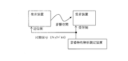
- the signal from the test signal generator is supplied to the sound source amplifier, the sound is radiated into the space by the speakers, and the sound is received by the measuring device. Therefore, correct impulse response measurement can be performed without using the same synchronization signal (clock pulse) for the test signal generator and the measurement device. For this reason, it is not necessary to route the cable to the microphone that receives the sound to measure the sound, or to move the measuring apparatus itself to the measurement point together with the microphone and connect it to the speaker side including the sound source amplifier by the cable.
- the impulse response characteristics from the acoustic device already mounted on the car to the position where the person listens (driving position) can be measured by a measuring instrument not connected to the acoustic device by a cable.
- a measuring instrument not connected to the acoustic device by a cable.
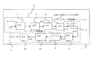
- the asynchronous system 1 includes a transmission side unit 2 and a reception side unit 3 that operate at different sampling clock frequencies (fs and f's).
- the impulse input I (k) in the frequency domain is input to the TSP filter 4 of the transfer function H (k), so that the output of the TSP filter 4 is H (k) I (k). can get.
- IDFT Inverse Discrete Fourier Transform
- IDFT is executed by the inverse discrete Fourier transform processing unit 5 on the H (k) I (k) that is the output of the TSP filter 4, thereby transmitting the data of the transmission side unit 2.
- a TSP signal h (n) which is a sample sequence synchronized with the sampling clock frequency fs, is obtained.
- the TSP signal h (t) is obtained by passing the TSP signal h (n) through the D / A converter 6.
- This X (l) and the TSP inverse filter H ⁇ 1 (l) 9 G ′ (l) is obtained by performing multiplication H ⁇ 1 (l) X (l) with the transfer characteristic of Next, IDFT processing unit 10 executes IDFT on G ′ (l) to obtain a sample string g (m), and passes this g (m) through D / A converter 11. Thus, an impulse response waveform g (t) is obtained.
- the D / A converters 6 and 11 shown in this example include a function of D / A converting an input signal, creating a pulse train with an analog gate or the like, and performing interpolation with an analog low-pass filter. Yes.
- the receiving side unit 3 performs DFT processing on the impulse response output x (m) by each of the plurality of TSP signals, performs synchronization vector addition averaging in the frequency domain, and then performs TSP inverse, which is an inverse function of the TSP filter.
- TSP inverse which is an inverse function of the TSP filter.
- the transfer characteristic of the filter H ⁇ 1 (l) is multiplied, the impulse response can be measured with higher accuracy when the influence of the sampling frequency deviation is taken into consideration for this inverse function.
- the synchronization vector addition average in the frequency domain and the correction principle of the TSP inverse filter H ⁇ 1 (k) will be described in detail.
- Step 1 From the A / D converter 7 of the receiving side unit 3, the entire signal data sequence x (m) to be synchronized and averaged output in synchronization with the sampling clock frequency f's of the receiving side unit 3 is read. . At this time, based on the data format determined by the transmission side unit 2, a plurality of signal data sequences are assumed that the sampling data sequence is continuous with reference to the synchronous data provided before the data sequence subject to synchronous addition averaging. Cut out.
- Step 2 A position error expressed by the number of sampling clocks of each signal data string on the time axis at which the correlation value reaches a peak and the phase between the sampling clocks, taking a cross-correlation between the head signal data string and the subsequent signal data (Phase difference) or synchronization position is estimated.
- Such position measurement of each data string by cross-correlation is suitable for impulse response measurement by the TSP method that can lengthen the data string on the receiving side (receiving unit 3). Is less susceptible to noise. This is because there is no correlation between the signal and noise, and the noise on one data string and the noise on the other.
- Step 3 Interpolation by a quadratic function is performed using the symmetry of the correlation shape in order to obtain the position of the accurate peak point of the cross-correlation value. Thereby, it is possible to accurately know the phase information of the synchronization position.
- Step 4 The DFT processing unit 8 executes DFT for each extracted data string.
- the sampling clock frequency of the receiving side unit 3 is different from the sampling clock frequency of the transmitting side unit 2, the phase of the position of each cut out signal data string varies. For this reason, the phase shift amount for each frequency in the frequency region corresponding to the position error (time shift) is corrected with respect to the DFT data obtained in advance, and complex vector addition averaging for each frequency is performed on the corrected DFT data. This is the synchronous vector addition average.
- the position error corresponds to around the phase in the frequency domain.
- the relationship between the time shift ⁇ and the phase ⁇ in the frequency domain is expressed mathematically.
- the angular frequency in the frequency domain is ⁇ and the phase rotation amount at each angular frequency is ⁇ ( ⁇ )
- the following equation is established.
- Step 5 The result of synchronous addition is multiplied with the TSP inverse filter H ⁇ 1 (l) 9 and the result is subjected to IDFT in the IDFT processing unit 10 to obtain an impulse response waveform g (m).
- the TSP inverse filter H ⁇ 1 (l ) Since the sample sequence x (m) of the response waveform of the reception side unit 3 is sampled at a frequency different from the sampling frequency of the transmission side unit 2, the TSP inverse filter H ⁇ 1 (l ) And IDFT of the result to obtain a pulse train of the impulse response, the TSP inverse filter H ⁇ 1 (l) must be generated corresponding to the sampling frequency of the receiving unit 3.
- the receiving unit 3 has a detected signal width of W N in the transmitting unit 2 when the processing is performed with the same total number N of samples as in the transmitting unit 2.
- the sample sequence x (m) obtained by the receiving side unit 3 is regarded as continuous x ( ⁇ t), and in the Fourier transform X (f) of x (t).
- the following formula (2) showing the relationship of the time scale factor ⁇ (E. Orang Brigham, “Fast Fourier Transform”, see Prentice-Hall Inc, Chapter 3 (1974)) will be considered.
- the scale factor ⁇ is a ratio between the above-described sampling frequency fs on the transmission side and the sampling frequency f ′s on the reception side.
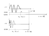
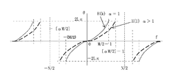
- FIG. 4 is a diagram schematically showing the relationship regarding the time scale factor ⁇ in the continuous system and the discrete system.
- the upper and middle stages show the relation of the equation (2), and the lower stage shows the discrete system DFT. Shows the relationship.
- the amplitude frequency characteristic and phase frequency characteristic of the signal x (t) having the time length Wt and the frequency band ⁇ Fm to + Fm at the measurement time T are shown in the upper stage, and the amplitude of the signal x ( ⁇ t) with the scale factor ⁇ > 1
- the frequency characteristics and phase frequency characteristics are shown in the middle section.
- the latter signal x ( ⁇ t) with a scale factor ⁇ > 1 has a waveform whose time length is Wt / ⁇ at the measurement time T, its frequency band is ⁇ Fm to + ⁇ Fm, and the amplitude of the amplitude frequency characteristic is 1 / ⁇ . Become.
- the continuous signal x ( ⁇ t) having the scale factor ⁇ is DFT
- the signal x ( ⁇ t) is repeated in the period T, and the frequency domain bandwidth ⁇ Fx to + Fx is expressed as Fx> ⁇ maxFm (where ⁇ max is (Maximum value of ⁇ > 0). Since it is a DFT, it becomes a periodic function with a period 2Fx in which the base frequency band is ⁇ Fx to + Fx in the frequency domain.
- a line spectrum for each 1 / T appears as the frequency characteristics of the signal, and the characteristics of the bands - ⁇ Fm to + ⁇ Fm are repeated on the frequency axis with a period of 2Fx.
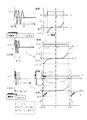
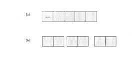
- FIG. 4 is a diagram schematically showing an actual response waveform x (t) based on the TSP signal. Further, since the signal sequence h (n) obtained by IDFT of the output H (k) I (k) of the TSP filter H (k) 4 by the IDFT processing unit 5 does not appear at the head portion as it is, FIG. The circular shift shown is performed. That is, although the leading signal sequence is shifted backward, the DFT assumes periodicity, so the result does not change even in this way.
- TSP filter transfer function
- DFT discrete Fourier transform
- Equation (4) 1 / ⁇ is substituted for k, and H (l) of the DFT with the amplitude 1 /
- H (l) (1 /
- ) exp ⁇ j ⁇ (l / ⁇ ) 2 ⁇ (1 /
- H * (l) (1 /
- H (l)
- H * -1 (l)
- the time length TL of the impulse response of the system under measurement is assumed to be equal to or shorter than the period T on the receiving
- an accurate impulse response sequence g (m) can be obtained by using the TSP inverse filter H ⁇ 1 (l) of equation (6). Further, since the correction TSP inverse filter H ⁇ 1 (l) can be corrected with a resolution within the numerical expression range, it is possible to ensure accuracy without increasing the data amount.
- the scale factor ⁇ at this time can be obtained by comparing the auto-correlation of the entire data string or the cross-correlation of adjacent data strings, so that the scale factor ⁇ is compared with a predetermined period on the transmission side.
- the method for increasing the accuracy by performing the interpolation process when obtaining the period by the cross-correlation process is the same as that for taking the above-mentioned synchronous addition average.
- the leading data string to be synchronously added is not used as a synchronous addition average data string if the waveform is not stable due to the transient response of the circuit system.
- each signal data row is cut out assuming that the sampling data row is continuous in a predetermined format with reference to the synchronous data provided before the data row to be synchronously added. Then, the phase error of each data string cut out by the cross correlation is obtained. Further, by taking the cross-correlation between adjacent data strings, the period of the data string is measured, and the scale factor ⁇ is obtained by comparing the period with the period of the data string predetermined on the transmission side.
- the impulse response measuring method and the impulse response measuring apparatus according to the present embodiment, even in an asynchronous system, even if the data sequence to be synchronously added is continuous or the interval between them is not constant, the synchronization is highly accurate. Addition can be performed.
- the impulse response measurement apparatus generates an input signal having an arbitrary waveform to be input to the system under measurement using the synchronization signal having the first sampling clock frequency (for example, fs).
- Signal converting means for example, the A / D converter 7 or DFT converter 8 of the receiving unit 3) for converting the signal under measurement into a discrete value system, the first sampling clock frequency, and the second sampling clock frequency ratio of the frequency (e.g., alpha) reverse to correct at least the phase of the inverse filter generating filter of the input signal in accordance with (e.g., TSP inverse filter H -1 (k))
- Has a filter correction means and characterized in that said measuring the impulse response of the measured system by using the inverse filter after correction, is the impulse response measuring device.
- the “inverse filter of the input signal generation filter” refers to a transfer function that is an inverse function of the function expressed by the discrete frequency characteristics of the input signal.
- the impulse response measuring apparatus (or impulse response measuring method) according to the present embodiment, even when the sampling clocks on the transmission side and the reception side are asynchronous when measuring the impulse response of the system under measurement, a simple apparatus is provided. Alternatively, a highly accurate impulse response measurement can be performed by signal processing.
- the signal from the test signal generator is supplied to the sound source amplifier, the sound is radiated into the space by the speakers, and the sound is received by the measuring device. Therefore, correct impulse response measurement can be performed without using the same synchronization signal (clock pulse) for the test signal generator and the measurement device. For this reason, it is not necessary to route the cable to the microphone that receives the sound to measure the sound, or to move the measuring apparatus itself to the measurement point together with the microphone and connect it to the speaker side including the sound source amplifier by the cable.
- the impulse response characteristics from the acoustic device already mounted on the car to the position where the person listens (driving position) with a measuring instrument not connected to the acoustic device with a cable.
- a measuring instrument it is possible to measure the impulse response characteristics of sound with a measuring instrument easily and with high accuracy by recording repeated TSP data for synchronous addition averaging on a CD and reproducing it with a CD player, which is an audio device. .
- the input signal generating means is a signal generator that repeatedly generates the input signal having the same arbitrary waveform at equal intervals or unequal intervals, or a medium (for example, the CD 12 in FIG. 8) on which the same signal as the input signal is recorded. ) And a regenerator (for example, a CD player 13) that repeatedly reproduces the input signal as a measurement signal source, and a repetitive signal generated from the measurement signal source is input to the system under test as the input signal,
- the signal conversion means receives the signal under measurement at a reception point, and uses each signal obtained from the waveform of the signal under measurement without using a common synchronization signal between the signal source for measurement and the reception point.
- the signal to be measured is segmented using the waveform information of the period, and the amount of time deviation of the waveform information of each segmented period becomes the true maximum value of the correlation value of the cross-correlation between the reference period and other periods Time lag
- the waveform of each period is converted into frequency domain amplitude and phase information, and then the phase is corrected based on the phase lag information for each frequency corresponding to the time lag.
- the amplitude and phase information of each period whose phase has been converted and corrected are added and averaged as a vector quantity, and the inverse filter correction means is obtained by autocorrelation of the signal under measurement or cross-correlation between adjacent signals of the repeated signal.
- the frequency ratio is obtained by comparing the signal period of the measured signal and the period of the repetitive signal, and the phase of the inverse filter in the frequency domain of the repetitive signal of the measurement signal source is corrected according to the frequency ratio. Then, the product of the result of the addition averaging in the signal conversion step and the inverse filter after the correction in the inverse filter correction step is calculated, and the calculation result is changed to the time domain. It may be measured the impulse response by.
- the signal conversion means performs discrete Fourier transform (DFT) on each period for correction of the time shift and converts it into amplitude and phase information of the frequency domain, and then a phase for each frequency corresponding to the time shift.
- the phase may be corrected based on the shift information, and the sum of the waveform information of each period may be obtained by averaging the complex vector quantities of each frequency.
- DFT discrete Fourier transform
- the scale factor ⁇ used for the inverse filter correction means may be obtained by interpolating the maximum correlation value by the autocorrelation or the cross correlation.
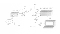
- the impulse response measuring method As an example of the impulse response measuring method according to the present invention, a method of measuring response characteristics from an acoustic device already mounted on a vehicle to a position (driving position) where a person listens without connecting the acoustic device and a measuring instrument with a cable. Will be described.
- a plurality of identical TSP data strings h (n) are continuously recorded on the CD 12.
- the data recorded on the CD 12 is read by the CD player 13 and the read signal h (t) is supplied to the speaker 14.
- the sound output from the speaker 14 is converted into an electric signal by the microphone 15 and then input to the ASA 16.
- the ASA 16 obtains the detection amplifier output (response waveform) x (t).
- the response waveform x (t) obtained by the ASA 16 includes spatial characteristics and speaker 14 characteristics.
- the ASA 16 transfers a plurality of data strings x (m) having continuous response waveforms to a PC (personal computer) 17 via an interface such as a USB.
- the PC 17 Based on the data format recorded on the CD 12, the PC 17 extracts a plurality of signal data strings on the basis of the synchronization data provided before the data string to be synchronized and added, and extracts a plurality of signal data strings.
- a position error time difference and autocorrelation
- ⁇ which is a sampling frequency ratio with the input side is obtained.
- a DFT is performed on the column x (m) by the DFT processing unit 8 to obtain each X (l), a correction phase amount is obtained from the previously obtained data position information, and a phase for each frequency of each X (l).
- the PC 17 performs synchronization vector addition on each of the plurality of phase-corrected X (l), and finally, the PC 17 performs the T correction with the scale factor ⁇ .
- the IDFT processing unit 10 performs fast inverse Fourier transform (IFFT / Inverse Fast Fourier Transform) processing to generate an impulse response sequence g (m), and the result is shown on the display unit.
- the synchronization data sequence is provided before the data sequence to be synchronized and added, so that on the reception side, the synchronization position is obtained by synchronizing with the synchronization data sequence in the received signal data. Can be determined. In other words, it is possible to know the location of data. However, data processing may be performed with reference to a position where data first appears without providing synchronization data.
- this embodiment uses the fact that the data format on the transmitting side is known. A continuous data string was cut out. However, if the same repeated data sequence subject to synchronous addition averaging is continuous, each data sequence can be cut out by executing autocorrelation to obtain a data repetition period.
- the effectiveness of the TSP inverse filter H ⁇ 1 (l) according to the present embodiment is confirmed by a simulation in a state where there is no measurement target such as an acoustic space. Therefore, when the sampling frequency on the transmitting side is shifted and the waveform on the receiving side is shifted in time, the impulse waveform is examined when the TSP inverse filter is corrected and not corrected.
- the simulation was performed under the following conditions.
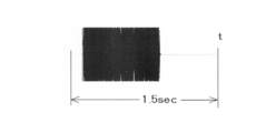
- the simulation result is shown in FIG. Further, the TSP waveform h (t) at this time is shown in FIG.
- the impulse response measuring method and the impulse response measuring apparatus generate an input signal having an arbitrary waveform to be input to the system under measurement using the synchronization signal having the first sampling clock frequency, and perform the second sampling.
- a synchronization signal having a clock frequency is used to convert a signal under measurement output from the system under measurement into a discrete value system, and a frequency ratio between the first sampling clock frequency and the second sampling clock frequency
- the phase of the inverse filter of the input signal is at least corrected according to the above, and the impulse response of the system under measurement may be measured using the corrected inverse filter.
- the impulse response measuring method and the impulse response measuring apparatus according to the present invention can be used for measuring transfer characteristics of a system under test such as an acoustic device, an acoustic space, and an electric signal transmission line.
Priority Applications (3)
| Application Number | Priority Date | Filing Date | Title |
|---|---|---|---|
| US13/384,381 US20120166123A1 (en) | 2009-07-17 | 2010-07-07 | Impulse response measuring method and impulse response measuring device |
| EP10799765.2A EP2455768A4 (en) | 2009-07-17 | 2010-07-07 | Impulse response measuring method and impulse response measuring device |
| CN201080032402.XA CN102472784B (zh) | 2009-07-17 | 2010-07-07 | 脉冲响应测定方法和脉冲响应测定装置 |
Applications Claiming Priority (2)
| Application Number | Priority Date | Filing Date | Title |
|---|---|---|---|
| JP2009168427A JP5540224B2 (ja) | 2009-07-17 | 2009-07-17 | インパルス応答測定方法およびインパルス応答測定装置 |
| JP2009-168427 | 2009-07-17 |
Publications (1)
| Publication Number | Publication Date |
|---|---|
| WO2011007706A1 true WO2011007706A1 (ja) | 2011-01-20 |
Family
ID=43449316
Family Applications (1)
| Application Number | Title | Priority Date | Filing Date |
|---|---|---|---|
| PCT/JP2010/061567 WO2011007706A1 (ja) | 2009-07-17 | 2010-07-07 | インパルス応答測定方法およびインパルス応答測定装置 |
Country Status (5)
| Country | Link |
|---|---|
| US (1) | US20120166123A1 (zh) |
| EP (1) | EP2455768A4 (zh) |
| JP (1) | JP5540224B2 (zh) |
| CN (1) | CN102472784B (zh) |
| WO (1) | WO2011007706A1 (zh) |
Cited By (3)
| Publication number | Priority date | Publication date | Assignee | Title |
|---|---|---|---|---|
| WO2015182608A1 (ja) * | 2014-05-27 | 2015-12-03 | 独立行政法人石油天然ガス・金属鉱物資源機構 | 振動検出システム、信号処理装置及び信号処理方法 |
| JP2018133682A (ja) * | 2017-02-15 | 2018-08-23 | 株式会社Jvcケンウッド | フィルタ生成装置、及びフィルタ生成方法 |
| RU2719325C2 (ru) * | 2015-09-08 | 2020-04-17 | Сэн-Гобэн Изовер | Способ и система получения по меньшей мере одного акустического параметра окружающей среды |
Families Citing this family (6)
| Publication number | Priority date | Publication date | Assignee | Title |
|---|---|---|---|---|
| JP6436616B2 (ja) * | 2013-06-12 | 2018-12-12 | キヤノン株式会社 | 計測装置、計測方法、および処理装置 |
| US9596553B2 (en) * | 2013-07-18 | 2017-03-14 | Harman International Industries, Inc. | Apparatus and method for performing an audio measurement sweep |
| JP6814957B2 (ja) | 2017-05-17 | 2021-01-20 | パナソニックIpマネジメント株式会社 | 再生システム、制御装置、制御方法、およびプログラム |
| CN107144343A (zh) * | 2017-07-10 | 2017-09-08 | 薛天 | 低频振动位移传感器组网方法、系统及装置 |
| JP6935370B2 (ja) * | 2018-07-24 | 2021-09-15 | アンリツ株式会社 | 信号発生装置および該装置を用いた周波数特性表示方法 |
| WO2021152918A1 (ja) * | 2020-01-31 | 2021-08-05 | 住友電気工業株式会社 | 検知システム、検知装置および検知方法 |
Citations (9)
| Publication number | Priority date | Publication date | Assignee | Title |
|---|---|---|---|---|
| JPH06265400A (ja) | 1993-03-11 | 1994-09-20 | Sony Corp | インパルス応答測定装置 |
| JP2725838B2 (ja) | 1989-06-05 | 1998-03-11 | 株式会社小野測器 | インパルス応答の測定方法 |
| JP2867769B2 (ja) | 1991-10-24 | 1999-03-10 | ヤマハ株式会社 | 音響測定方法およびその装置 |
| JP2004193782A (ja) * | 2002-12-09 | 2004-07-08 | Toa Corp | スピーカとマイクロホン間の音波伝搬時間測定方法およびその装置 |
| JP3718642B2 (ja) | 2001-06-12 | 2005-11-24 | エタニ電機株式会社 | 音響機器、音響空間、電気信号伝送線路等の伝達特性測定方法 |
| WO2006011356A1 (ja) | 2004-07-29 | 2006-02-02 | Wakayama University | インパルス応答測定方法及び装置 |
| JP3766975B1 (ja) | 2004-08-25 | 2006-04-19 | 辰哉 加藤 | パラメトリックな時間引き延ばしパルス生成装置 |
| JP2007156393A (ja) | 2005-11-09 | 2007-06-21 | Pioneer Electronic Corp | インパルス応答検出装置及びインパルス応答検出プログラム |
| JP2007232492A (ja) | 2006-02-28 | 2007-09-13 | Kawai Musical Instr Mfg Co Ltd | 伝達特性測定方法および装置 |
Family Cites Families (10)
| Publication number | Priority date | Publication date | Assignee | Title |
|---|---|---|---|---|
| US5404379A (en) * | 1991-01-28 | 1995-04-04 | Industrial Technology Research Institute | Timing recovery method and system |
| US6307868B1 (en) * | 1995-08-25 | 2001-10-23 | Terayon Communication Systems, Inc. | Apparatus and method for SCDMA digital data transmission using orthogonal codes and a head end modem with no tracking loops |
| US7046694B2 (en) * | 1996-06-19 | 2006-05-16 | Digital Radio Express, Inc. | In-band on-channel digital broadcasting method and system |
| US6005901A (en) * | 1997-02-27 | 1999-12-21 | Advanced Micro Devices | Arrangement for asynchronous decimation using a frequency ratio estimator and method thereof |
| AU5009399A (en) * | 1998-09-24 | 2000-05-04 | Sony Corporation | Impulse response collecting method, sound effect adding apparatus, and recording medium |
| US6507606B2 (en) * | 2000-03-29 | 2003-01-14 | Symmetrican, Inc. | Asymmetric digital subscriber line methods suitable for long subscriber loops |
| US20030112861A1 (en) * | 2001-12-18 | 2003-06-19 | Erdogan Alper Tunga | Method and system for adaptively training time domain equalizers |
| JP4184420B2 (ja) * | 2005-02-28 | 2008-11-19 | パイオニア株式会社 | 特性測定装置及び特性測定プログラム |
| JP4285469B2 (ja) * | 2005-10-18 | 2009-06-24 | ソニー株式会社 | 計測装置、計測方法、音声信号処理装置 |
| JP4466658B2 (ja) * | 2007-02-05 | 2010-05-26 | ソニー株式会社 | 信号処理装置、信号処理方法、プログラム |
-
2009
- 2009-07-17 JP JP2009168427A patent/JP5540224B2/ja active Active
-
2010
- 2010-07-07 CN CN201080032402.XA patent/CN102472784B/zh not_active Expired - Fee Related
- 2010-07-07 EP EP10799765.2A patent/EP2455768A4/en not_active Withdrawn
- 2010-07-07 WO PCT/JP2010/061567 patent/WO2011007706A1/ja active Application Filing
- 2010-07-07 US US13/384,381 patent/US20120166123A1/en not_active Abandoned
Patent Citations (9)
| Publication number | Priority date | Publication date | Assignee | Title |
|---|---|---|---|---|
| JP2725838B2 (ja) | 1989-06-05 | 1998-03-11 | 株式会社小野測器 | インパルス応答の測定方法 |
| JP2867769B2 (ja) | 1991-10-24 | 1999-03-10 | ヤマハ株式会社 | 音響測定方法およびその装置 |
| JPH06265400A (ja) | 1993-03-11 | 1994-09-20 | Sony Corp | インパルス応答測定装置 |
| JP3718642B2 (ja) | 2001-06-12 | 2005-11-24 | エタニ電機株式会社 | 音響機器、音響空間、電気信号伝送線路等の伝達特性測定方法 |
| JP2004193782A (ja) * | 2002-12-09 | 2004-07-08 | Toa Corp | スピーカとマイクロホン間の音波伝搬時間測定方法およびその装置 |
| WO2006011356A1 (ja) | 2004-07-29 | 2006-02-02 | Wakayama University | インパルス応答測定方法及び装置 |
| JP3766975B1 (ja) | 2004-08-25 | 2006-04-19 | 辰哉 加藤 | パラメトリックな時間引き延ばしパルス生成装置 |
| JP2007156393A (ja) | 2005-11-09 | 2007-06-21 | Pioneer Electronic Corp | インパルス応答検出装置及びインパルス応答検出プログラム |
| JP2007232492A (ja) | 2006-02-28 | 2007-09-13 | Kawai Musical Instr Mfg Co Ltd | 伝達特性測定方法および装置 |
Non-Patent Citations (3)
| Title |
|---|
| E. ORAN BRIGHAM: "The Fast Fourier Transform", 1974, PRENTICE-HALL INC. |
| HINO; TSUCHIYA; ENDO: "An Examination of the Synchronous Addition Method under an Asynchronous Measurement System", AES 10TH REGIONAL CONVENTION, June 2001 (2001-06-01) |
| JURO OHGA; YOSHIO YAMASAKI; YUTAKA KANEDA: "Acoustic Systems and Digital Processing", THE INSTITUTE OF ELECTRONICS, INFORMATION AND COMMUNICATION ENGINEERS, 1995, pages 158 - 159 |
Cited By (5)
| Publication number | Priority date | Publication date | Assignee | Title |
|---|---|---|---|---|
| WO2015182608A1 (ja) * | 2014-05-27 | 2015-12-03 | 独立行政法人石油天然ガス・金属鉱物資源機構 | 振動検出システム、信号処理装置及び信号処理方法 |
| JP2015224916A (ja) * | 2014-05-27 | 2015-12-14 | 独立行政法人石油天然ガス・金属鉱物資源機構 | 振動検出システム、信号処理装置及び信号処理方法 |
| US10281601B2 (en) | 2014-05-27 | 2019-05-07 | Japan Oil, Gas And Metals National Corporation | Vibration detecting system, signal processing apparatus and signal processing method |
| RU2719325C2 (ru) * | 2015-09-08 | 2020-04-17 | Сэн-Гобэн Изовер | Способ и система получения по меньшей мере одного акустического параметра окружающей среды |
| JP2018133682A (ja) * | 2017-02-15 | 2018-08-23 | 株式会社Jvcケンウッド | フィルタ生成装置、及びフィルタ生成方法 |
Also Published As
| Publication number | Publication date |
|---|---|
| CN102472784B (zh) | 2014-07-16 |
| EP2455768A1 (en) | 2012-05-23 |
| CN102472784A (zh) | 2012-05-23 |
| JP2011022055A (ja) | 2011-02-03 |
| US20120166123A1 (en) | 2012-06-28 |
| EP2455768A4 (en) | 2017-10-25 |
| JP5540224B2 (ja) | 2014-07-02 |
Similar Documents
| Publication | Publication Date | Title |
|---|---|---|
| JP5540224B2 (ja) | インパルス応答測定方法およびインパルス応答測定装置 | |
| US20080025521A1 (en) | Impulse Response Measurement Method and Device | |
| JP6508539B2 (ja) | 音場収音装置および方法、音場再生装置および方法、並びにプログラム | |
| US20060267813A1 (en) | Analog/digital converter and program therefor | |
| JP2011022055A5 (zh) | ||
| JP2020036271A (ja) | 伝達関数生成装置、伝達関数生成方法、およびプログラム | |
| JP2002365320A (ja) | 音響用ならびに電気電子伝送路用伝達特性の測定方法 | |
| JP2019052938A (ja) | 光反射測定装置及びその方法 | |
| JP5035815B2 (ja) | 周波数測定装置 | |
| Hafez et al. | Automatic detection of geomagnetic sudden commencement via time–frequency clusters | |
| JP2007017415A (ja) | インパルス応答の時間差測定方法 | |
| JP3139803B2 (ja) | インパルス応答測定装置 | |
| Novak et al. | Impulse Response Measurements using MLS Technique on Nonsynchronous Devices | |
| JP4247168B2 (ja) | 音場特性測定システム | |
| CN110231515B (zh) | 一种绝缘寿命试验介质损耗因数的实时在线测量方法 | |
| JP3795446B2 (ja) | Mtie試験信号発生装置 | |
| JP5802573B2 (ja) | 計測器およびその制御方法 | |
| Gamper | Clock drift estimation and compensation for asynchronous impulse response measurements | |
| JP2008224306A (ja) | スペクトラム解析装置 | |
| JP4827595B2 (ja) | インパルス応答検出装置及びインパルス応答検出プログラム | |
| Takeuchi et al. | A method for analyzing sampling jitter in audio equipment | |
| TWI792779B (zh) | 用於同步聲音播放及記錄時脈的系統及其使用之方法 | |
| Mori et al. | Robustness of pure white pseudonoise signal to temporal fluctuation in impulse response measurement | |
| JP5544549B2 (ja) | 特異点を有する信号処理システムおよび情報記憶媒体 | |
| CN115792446A (zh) | 一种单相输电线路可听噪声声源的测试方法及装置 |
Legal Events
| Date | Code | Title | Description |
|---|---|---|---|
| WWE | Wipo information: entry into national phase |
Ref document number: 201080032402.X Country of ref document: CN |
|
| 121 | Ep: the epo has been informed by wipo that ep was designated in this application |
Ref document number: 10799765 Country of ref document: EP Kind code of ref document: A1 |
|
| NENP | Non-entry into the national phase |
Ref country code: DE |
|
| WWE | Wipo information: entry into national phase |
Ref document number: 2010799765 Country of ref document: EP |
|
| WWE | Wipo information: entry into national phase |
Ref document number: 13384381 Country of ref document: US |