JP6436616B2 - 計測装置、計測方法、および処理装置 - Google Patents
計測装置、計測方法、および処理装置 Download PDFInfo
- Publication number
- JP6436616B2 JP6436616B2 JP2013123379A JP2013123379A JP6436616B2 JP 6436616 B2 JP6436616 B2 JP 6436616B2 JP 2013123379 A JP2013123379 A JP 2013123379A JP 2013123379 A JP2013123379 A JP 2013123379A JP 6436616 B2 JP6436616 B2 JP 6436616B2
- Authority
- JP
- Japan
- Prior art keywords
- signal
- period
- position data
- output
- time
- Prior art date
- Legal status (The legal status is an assumption and is not a legal conclusion. Google has not performed a legal analysis and makes no representation as to the accuracy of the status listed.)
- Active
Links
- 238000012545 processing Methods 0.000 title claims description 54
- 238000000034 method Methods 0.000 title claims description 15
- 238000005259 measurement Methods 0.000 claims description 74
- 238000012937 correction Methods 0.000 claims description 67
- 230000001360 synchronised effect Effects 0.000 claims description 41
- 238000001514 detection method Methods 0.000 claims description 28
- 238000006073 displacement reaction Methods 0.000 claims description 24
- 238000006243 chemical reaction Methods 0.000 claims description 11
- 238000000691 measurement method Methods 0.000 claims description 2
- 230000001133 acceleration Effects 0.000 description 9
- 238000010586 diagram Methods 0.000 description 9
- 230000033001 locomotion Effects 0.000 description 8
- 230000008859 change Effects 0.000 description 7
- 230000004044 response Effects 0.000 description 6
- 230000003287 optical effect Effects 0.000 description 5
- 230000008569 process Effects 0.000 description 5
- 238000013461 design Methods 0.000 description 4
- 230000005540 biological transmission Effects 0.000 description 3
- 238000007405 data analysis Methods 0.000 description 3
- 238000013480 data collection Methods 0.000 description 3
- 230000000694 effects Effects 0.000 description 3
- 238000007689 inspection Methods 0.000 description 3
- 230000010355 oscillation Effects 0.000 description 2
- 238000005070 sampling Methods 0.000 description 2
- 206010004966 Bite Diseases 0.000 description 1
- 230000008901 benefit Effects 0.000 description 1
- 238000004891 communication Methods 0.000 description 1
- 125000004122 cyclic group Chemical group 0.000 description 1
- 230000001934 delay Effects 0.000 description 1
- 230000003111 delayed effect Effects 0.000 description 1
- 230000010354 integration Effects 0.000 description 1
- 238000012544 monitoring process Methods 0.000 description 1
- 230000009466 transformation Effects 0.000 description 1
Images


Classifications
-
- G—PHYSICS
- G01—MEASURING; TESTING
- G01D—MEASURING NOT SPECIALLY ADAPTED FOR A SPECIFIC VARIABLE; ARRANGEMENTS FOR MEASURING TWO OR MORE VARIABLES NOT COVERED IN A SINGLE OTHER SUBCLASS; TARIFF METERING APPARATUS; MEASURING OR TESTING NOT OTHERWISE PROVIDED FOR
- G01D5/00—Mechanical means for transferring the output of a sensing member; Means for converting the output of a sensing member to another variable where the form or nature of the sensing member does not constrain the means for converting; Transducers not specially adapted for a specific variable
- G01D5/26—Mechanical means for transferring the output of a sensing member; Means for converting the output of a sensing member to another variable where the form or nature of the sensing member does not constrain the means for converting; Transducers not specially adapted for a specific variable characterised by optical transfer means, i.e. using infrared, visible, or ultraviolet light
- G01D5/32—Mechanical means for transferring the output of a sensing member; Means for converting the output of a sensing member to another variable where the form or nature of the sensing member does not constrain the means for converting; Transducers not specially adapted for a specific variable characterised by optical transfer means, i.e. using infrared, visible, or ultraviolet light with attenuation or whole or partial obturation of beams of light
- G01D5/34—Mechanical means for transferring the output of a sensing member; Means for converting the output of a sensing member to another variable where the form or nature of the sensing member does not constrain the means for converting; Transducers not specially adapted for a specific variable characterised by optical transfer means, i.e. using infrared, visible, or ultraviolet light with attenuation or whole or partial obturation of beams of light the beams of light being detected by photocells
- G01D5/347—Mechanical means for transferring the output of a sensing member; Means for converting the output of a sensing member to another variable where the form or nature of the sensing member does not constrain the means for converting; Transducers not specially adapted for a specific variable characterised by optical transfer means, i.e. using infrared, visible, or ultraviolet light with attenuation or whole or partial obturation of beams of light the beams of light being detected by photocells using displacement encoding scales
-
- G—PHYSICS
- G01—MEASURING; TESTING
- G01D—MEASURING NOT SPECIALLY ADAPTED FOR A SPECIFIC VARIABLE; ARRANGEMENTS FOR MEASURING TWO OR MORE VARIABLES NOT COVERED IN A SINGLE OTHER SUBCLASS; TARIFF METERING APPARATUS; MEASURING OR TESTING NOT OTHERWISE PROVIDED FOR
- G01D5/00—Mechanical means for transferring the output of a sensing member; Means for converting the output of a sensing member to another variable where the form or nature of the sensing member does not constrain the means for converting; Transducers not specially adapted for a specific variable
- G01D5/12—Mechanical means for transferring the output of a sensing member; Means for converting the output of a sensing member to another variable where the form or nature of the sensing member does not constrain the means for converting; Transducers not specially adapted for a specific variable using electric or magnetic means
- G01D5/244—Mechanical means for transferring the output of a sensing member; Means for converting the output of a sensing member to another variable where the form or nature of the sensing member does not constrain the means for converting; Transducers not specially adapted for a specific variable using electric or magnetic means influencing characteristics of pulses or pulse trains; generating pulses or pulse trains
- G01D5/24471—Error correction
Description
まず、本発明の第1実施形態に係る計測装置について説明する。本実施形態に係る計測装置は、対象物(計測対象物)の変位に伴って変化する信号を検出して変位を計測する、いわゆるエンコーダであり、以下、対象物の位置の変化、または変位を計測する光学式のアブソリュートエンコーダを例に説明する。なお、本発明の計測装置は、このような位置の変化、もしくは変位を計測するエンコーダに限らず、角度の変化、もしくは変位を計測するエンコーダ、またはインクリメンタルエンコーダにも適用可能である。
移動速度[m/s]=(今回の位置データ[m]−前回の位置データ[m])/
位置計測周期[s] (1)
例えば、位置データP3_1の時点での速度V3_1を求める場合には、式(1)は、以下の式(2)のようになる。ただし、位置計測周期は、10μs(meas信号111の周波数100kHzより)である。
V3_1[m/s]=(P3_1[m]−P2_10[m])/10[μs] (2)
制御時補正位置データ[m]=今回の位置データ[m]+移動速度[m/s]×
制御時点との時間差[s] (3)
例えば、制御時補正位置データP4’_1は、以下の式(4)により求められる。ただし、ここでは制御時点との時間差を100μsとしている。
P4’_1[m]=P3_1[m]+V3_1[m/s]×100[μs] (4)
計測時補正位置データ[m]=今回の位置データ[m]+移動速度[m/s]×
Tsp[s] (5)
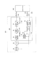
ただし、移動速度を求める式は、上記式(1)と同一である。また、Tspは、図8にも示すとおり、今回の位置データの計測開始時点とデータ要求時点との時間差であり、図1では、time_delay信号114として、時間差計測部60から位置補正部40へと入力される。
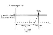
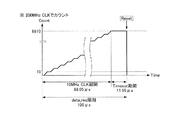
補正値演算基準クロック番号=(全クロック数+1)−今クロック番号 (6)
例えば、位置データP2_10については、10+1−10=1より、補正値演算基準クロック番号は1となる。すなわち、位置データP2_10は、データ要求時点に対して1つ前のクロックで計測した位置データということになる。最終的に、Tspは、以下の式(7)により求められる。
Tsp[s]=meas信号の周期[s]×補正値演算基準クロック番号 (7)
例えば、図8のTspは、以下の式(8)のように求められる。
Tsp[s]=10[μs]×1=10[μs] (8)
P3’_1[m]=P2_10[m]+V2_10[m/s]×10[μs] (9)
そして、位置データ出力部50は、この式(9)にて求められる計測時補正位置データのうち、data_req3のデータ要求時点に最も時間的に近い計測時補正位置データを、上位システム500へと出力する。
Tsp’[s]=Tsp[s]+検出部10の受光時間[s]/2 (10)
なお、検出部10の受光時間は、設計値から求めてもよいし、実際に計測して求めてもよい。
制御時補正位置データ[m]=計測時補正位置データ[m]+移動速度[m/s]×
制御時点との時間差[s] (11)
例えば、図8の制御時補正位置データP4’_1を求める場合には、以下の式(12)のようになる。ただし、ここでは制御時点との時間差を100μsとしている。
P4’_1[m]=P3’_1[m]+V2_10[m/s]×100[μs](12)
P3’_1[m]=P2_1[m]+V2_1[m/s]×100[μs] (13)
そして、実際のdata_req3の時点での位置データP3_1と、ここで得られた計測時補正位置データP3’_1との差が、従来生じ得る位置誤差となる。図10は、図9の加速度動作をする対象物について求めた位置誤差を示すグラフである。特に、図10(a)は、計測時補正に係る位置誤差に関するものである。図10(a)中の実線で示す従来の誤差量については、横軸の時間に対して、左側縦軸で示している。誤差量は、対象物の加速度の大きさに比例しており、最大で98nmとなる。
P4’_1[m]=P3’_1[m]+V2_1[m/s]×100[μs](14)
そして、実際のdata_req4の時点での位置データP4_1と、ここで得られた計測時補正位置データP4’_1との差が、従来生じ得る位置誤差となる。図10(b)は、制御時補正に係る位置誤差に関するものである。図10(b)中の実線で示す従来の誤差量は、対象物の加速度の大きさに比例しており、最大で294nmとなる。
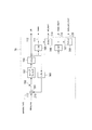
次に、本発明の第2実施形態に係る計測装置について説明する。図12は、本実施形態に係るエンコーダ300の信号処理系の構成を示すブロック図である。本実施形態に係るエンコーダ300の特徴は、第1実施形態に係るエンコーダ100が発振器80を有しているのに対してその発振器を含まず、上位システム500からclk_IN信号230の入力を受ける点にある。なお、エンコーダ300のその他の構成は、第1実施形態に係るエンコーダ100と基本的に同一であるので、図12において同一の符号を付し、説明を省略する。
30 位置演算部
40 位置補正部
70 同期高速クロック生成部
100 エンコーダ
111 meas信号
210 data_req信号
Claims (10)
- 対象物の変位に伴って変化する信号の検出を行って前記対象物の位置を計測する計測装置であって、
1周期の中に所定周期の信号を出力する第1期間と一定値の信号を出力する第2期間を含んでおり、前記対象物の位置の出力用位置データを要求する要求信号に基づいて、該要求信号の周期より短い周期を有する第1クロック信号を生成するクロック生成部と、
前記第1クロック信号の周期ごとに前記検出を行う検出部と、
前記検出部の出力に基づいて、前記対象物の処理用位置データを得る演算部と、
前記演算部からの複数の前記処理用位置データに基づいて単位時間当たりの前記対象物の変位量を得、前記出力用位置データの要求信号が受信される前に前記出力用位置データのための計測が開始された時点と前記出力用位置データの前記要求信号が受信された時点との間の時間差と、前記変位量とに基づいて、前記演算部が得た処理用位置データのうち補正対象の処理用位置データを補正する補正部と、
を有しており、
前記クロック生成部は、前記第1期間では、前記要求信号に含まれる前記所定周期の信号に同期した前記第1クロック信号を出力し、前記第2期間では、前記第1期間に出力した前記要求信号の周期より短い周期を有する第1クロック信号を継続して出力するように動作が維持される位相同期部を含む、
ことを特徴とする計測装置。 - 前記クロック生成部は、前記要求信号に同期し且つ該要求信号の周期より短い周期を有する第2クロック信号に同期して前記第1クロック信号を生成する、ことを特徴とする請求項1に記載の計測装置。
- 前記時間差を計測する時間差計測部を有する、ことを特徴とする請求項1または2に記載の計測装置。
- 前記補正部は、前記補正対象の処理用位置データを補正して、前記要求信号を受信した時点における出力用位置データを得る、
ことを特徴とする請求項1ないし3のいずれか1項に記載の計測装置。 - 前記補正部は、前記補正対象の処理用位置データを補正して、前記要求信号を受信した時点より後の時点における出力用位置データを得る、
ことを特徴とする請求項1ないし4のいずれか1項に記載の計測装置。 - 前記検出部は、光電変換素子を含み、
前記出力用位置データのための前記計測が開始される前記時点は、前記光電変換素子の受光時間の中間に設定されている、ことを特徴とする請求項1ないし5のいずれか1項に記載の計測装置。 - 対象物を処理する処理装置であって、
前記対象物の変位を計測する請求項1ないし6のいずれか1項に記載の計測装置を有することを特徴とする処理装置。 - 対象物の変位に伴って変化する信号の検出を行って前記対象物の位置を計測する計測方法であって、
1周期の中に所定周期の信号を出力する第1期間と一定値の信号を出力する第2期間を含んでおり、前記対象物の位置の出力用位置データを要求する要求信号に基づいて、該要求信号の周期より短い周期を有する第1クロック信号を生成し、
前記第1クロック信号の周期ごとに前記検出を行い、
前記検出に基づいて、前記対象物の処理用位置データを得、
複数の前記処理用位置データに基づいて単位時間当たりの前記対象物の変位量を得、前記出力用位置データの要求信号が受信される前に前記出力用位置データのための計測が開始された時点と前記出力用位置データの前記要求信号が受信された時点との間の時間差と、前記変位量とに基づいて、演算部が得た処理用位置データのうち補正対象の処理用位置データを補正し、
前記第1期間では、前記要求信号に含まれる前記所定周期の信号に同期した前記第1クロック信号を出力し、前記第2期間では、前記第1期間に出力した前記要求信号の周期より短い周期を有する第1クロック信号を継続して出力することが維持される、
ことを特徴とする計測方法。 - 対象物を移動させる機構と、該対象物の変位に伴って変化する信号の検出を行って前記対象物の位置を計測する計測装置とを有する装置であって、
1周期の中に所定周期の信号を出力する第1期間と一定値の信号を出力する第2期間を含んでおり、前記対象物の位置の出力用位置データを要求する要求信号に基づいて、該要求信号の周期より短い周期を有する第1クロック信号を生成するクロック生成部と、
前記第1クロック信号の周期ごとに前記検出を行う検出部と、
前記検出部の出力に基づいて、前記対象物の処理用位置データを得る演算部と、
前記演算部からの複数の前記処理用位置データに基づいて単位時間当たりの前記対象物の変位量を得、前記出力用位置データの要求信号が受信される前に前記出力用位置データのための計測が開始された時点と前記出力用位置データの前記要求信号が受信された時点との間の時間差と、前記変位量とに基づいて、前記演算部が得た処理用位置データのうち補正対象の処理用位置データを補正する補正部と、
を有しており、
前記クロック生成部は、前記第1期間では、前記要求信号に含まれる前記所定周期の信号に同期した前記第1クロック信号を出力し、前記第2期間では、前記第1期間に出力した前記要求信号の周期より短い周期を有する第1クロック信号を継続して出力するように動作が維持される位相同期部を含む、
ことを特徴とする装置。 - 対象物の位置を計測する、請求項1乃至6いずれか1項に記載の計測装置と、
該計測装置に出力用位置データの要求信号を送信するシステムと、
を備えることを特徴とする産業用装置。
Priority Applications (3)
| Application Number | Priority Date | Filing Date | Title |
|---|---|---|---|
| JP2013123379A JP6436616B2 (ja) | 2013-06-12 | 2013-06-12 | 計測装置、計測方法、および処理装置 |
| US14/299,581 US9488501B2 (en) | 2013-06-12 | 2014-06-09 | Measuring apparatus, measuring method, and processing apparatus thereof that obtain displacement amount of an object using clock in synchronization with data request signal |
| EP14171884.1A EP2813820B1 (en) | 2013-06-12 | 2014-06-11 | Measuring apparatus, measuring method, and processing apparatus |
Applications Claiming Priority (1)
| Application Number | Priority Date | Filing Date | Title |
|---|---|---|---|
| JP2013123379A JP6436616B2 (ja) | 2013-06-12 | 2013-06-12 | 計測装置、計測方法、および処理装置 |
Publications (3)
| Publication Number | Publication Date |
|---|---|
| JP2014240790A JP2014240790A (ja) | 2014-12-25 |
| JP2014240790A5 JP2014240790A5 (ja) | 2016-07-28 |
| JP6436616B2 true JP6436616B2 (ja) | 2018-12-12 |
Family
ID=50927970
Family Applications (1)
| Application Number | Title | Priority Date | Filing Date |
|---|---|---|---|
| JP2013123379A Active JP6436616B2 (ja) | 2013-06-12 | 2013-06-12 | 計測装置、計測方法、および処理装置 |
Country Status (3)
| Country | Link |
|---|---|
| US (1) | US9488501B2 (ja) |
| EP (1) | EP2813820B1 (ja) |
| JP (1) | JP6436616B2 (ja) |
Families Citing this family (11)
| Publication number | Priority date | Publication date | Assignee | Title |
|---|---|---|---|---|
| JP6168762B2 (ja) * | 2012-12-14 | 2017-07-26 | キヤノン株式会社 | アブソリュートエンコーダ |
| EP3086126B1 (de) * | 2015-04-23 | 2020-12-16 | Siemens Healthcare Diagnostics Products GmbH | Verfahren zur bestimmung der lage von messpositionen in einem messsystem |
| CN105119907A (zh) * | 2015-07-22 | 2015-12-02 | 哈尔滨工业大学 | 一种基于FPGA的BiSS-C通信协议方法 |
| CN106066837B (zh) * | 2016-05-30 | 2018-12-18 | 哈工大机器人集团有限公司 | 一种基于fpga的biss-c协议通用控制器 |
| JP6779081B2 (ja) * | 2016-09-28 | 2020-11-04 | キヤノン株式会社 | 記録素子基板、記録ヘッド、および記録装置 |
| JP2018200666A (ja) * | 2017-05-25 | 2018-12-20 | ルネサスエレクトロニクス株式会社 | 検出システム、センサ及びマイクロコンピュータ |
| US20180340803A1 (en) * | 2017-05-25 | 2018-11-29 | Renesas Electronics Corporation | Detection system, sensor and microcomputer |
| US9877042B1 (en) * | 2017-05-26 | 2018-01-23 | Mitutoyo Corporation | Position encoder sample timing system |
| JP7277274B2 (ja) * | 2019-06-12 | 2023-05-18 | ファナック株式会社 | エンコーダおよびデータ送信方法 |
| JP7452330B2 (ja) | 2020-08-26 | 2024-03-19 | ブラザー工業株式会社 | モータ制御装置、及びモータ制御方法 |
| CN112306112B (zh) * | 2020-10-09 | 2023-11-24 | 武汉华之洋科技有限公司 | 一种带有高频测角机构的转台/摇摆台及测角方法 |
Family Cites Families (16)
| Publication number | Priority date | Publication date | Assignee | Title |
|---|---|---|---|---|
| JPH05240631A (ja) * | 1992-02-27 | 1993-09-17 | Yokogawa Electric Corp | 光学式エンコーダ |
| JP3072938B2 (ja) * | 1992-05-15 | 2000-08-07 | オークマ株式会社 | 位置検出装置 |
| JP3367260B2 (ja) | 1995-03-24 | 2003-01-14 | 三菱電機株式会社 | エンコーダ装置及びサーボモーター制御装置 |
| DE10054070A1 (de) | 2000-10-31 | 2002-05-08 | Heidenhain Gmbh Dr Johannes | Positionsmeßgerät und Verfahren zur Bestimmung einer Position |
| DE10149174A1 (de) * | 2001-10-04 | 2003-04-17 | Heidenhain Gmbh Dr Johannes | Verfahren und Vorrichtung zur Positionsbestimmung |
| US6639529B1 (en) * | 2002-05-14 | 2003-10-28 | Mitutoyo Corporation | System and method for delay calibration in position encoders |
| US7094978B2 (en) * | 2002-11-15 | 2006-08-22 | Mitutoyo Corporation | System and method for generating a high speed estimated position output for a position encoder |
| JP4179143B2 (ja) * | 2003-11-25 | 2008-11-12 | 松下電器産業株式会社 | アブソリュートエンコーダ |
| JP2006048380A (ja) * | 2004-08-04 | 2006-02-16 | Keyence Corp | 光学式変位計のデータ伝送方法及び光学式変位計 |
| JP4953714B2 (ja) | 2005-08-11 | 2012-06-13 | 株式会社ミツトヨ | エンコーダ出力の内挿方法及び内挿回路 |
| JP2008032562A (ja) * | 2006-07-28 | 2008-02-14 | Ntn Corp | 回転検出装置および回転検出装置付き軸受 |
| JP5540224B2 (ja) * | 2009-07-17 | 2014-07-02 | エタニ電機株式会社 | インパルス応答測定方法およびインパルス応答測定装置 |
| JP5129224B2 (ja) * | 2009-10-30 | 2013-01-30 | オークマ株式会社 | 位置検出装置 |
| JP2011209375A (ja) * | 2010-03-29 | 2011-10-20 | Dainippon Screen Mfg Co Ltd | パターン描画装置およびパターン描画方法 |
| JP5251960B2 (ja) | 2010-11-05 | 2013-07-31 | 株式会社安川電機 | エンコーダ、サーボユニット及び位置データ算出方法 |
| DE102011079961A1 (de) * | 2011-07-28 | 2013-01-31 | Dr. Johannes Heidenhain Gmbh | Vorrichtung und Verfahren zur Winkelmessung |
-
2013
- 2013-06-12 JP JP2013123379A patent/JP6436616B2/ja active Active
-
2014
- 2014-06-09 US US14/299,581 patent/US9488501B2/en not_active Expired - Fee Related
- 2014-06-11 EP EP14171884.1A patent/EP2813820B1/en not_active Not-in-force
Also Published As
| Publication number | Publication date |
|---|---|
| EP2813820B1 (en) | 2017-12-20 |
| EP2813820A1 (en) | 2014-12-17 |
| JP2014240790A (ja) | 2014-12-25 |
| US20140367561A1 (en) | 2014-12-18 |
| US9488501B2 (en) | 2016-11-08 |
Similar Documents
| Publication | Publication Date | Title |
|---|---|---|
| JP6436616B2 (ja) | 計測装置、計測方法、および処理装置 | |
| US7945821B2 (en) | Time lag measuring device, distance measuring apparatus and distance measuring method | |
| US10072950B2 (en) | Encoder and method of outputting measurement value of position or angle | |
| US7777865B2 (en) | Time difference measuring device, measuring method, distance measuring device, and distance measuring method | |
| US8531651B2 (en) | Distance measuring device, distance measuring method, program, and integrated circuit | |
| JP5932285B2 (ja) | エンコーダおよびこれを備えた装置 | |
| EP2581713B1 (en) | Encoder and apparatus using the same | |
| JP5753449B2 (ja) | 光波距離測定方法及び光波距離装置 | |
| EP2343573B1 (en) | Electro-optical distance measuring device | |
| CN104101369A (zh) | 位置检测设备 | |
| JP2014190905A (ja) | 位置検出手段 | |
| US10393550B2 (en) | Encoder and apparatus having the same | |
| JP5581174B2 (ja) | 障害物検知装置 | |
| JP2015179051A (ja) | 位置検出装置及びそれを有するレンズ装置及び光学操作装置 | |
| KR101223953B1 (ko) | 표준 시각 동기용 주파수를 이용한 자체 온도 보상 기능을 갖는 고 분해능 정밀 시각 측정 장치 및 방법 | |
| JP2013079915A (ja) | 絶対測長型エンコーダ | |
| JP2015161595A (ja) | 光学式エンコーダ | |
| JP4202751B2 (ja) | 位置設定をするための方法及びこの方法を実施するための位置測定装置 | |
| JP2003254784A (ja) | 変位校正方法及び装置 | |
| JP2014115203A (ja) | 距離計測装置 | |
| JP4227352B2 (ja) | 一致検出装置及び方法 | |
| WO2019176751A1 (ja) | 光検出装置、光検出方法および光学式測距センサ | |
| JPH0933284A (ja) | 光学式エンコーダ | |
| JP4230244B2 (ja) | 形状測定装置 | |
| WO2012029778A1 (ja) | エンコーダ用信号処理回路 |
Legal Events
| Date | Code | Title | Description |
|---|---|---|---|
| A521 | Request for written amendment filed |
Free format text: JAPANESE INTERMEDIATE CODE: A523 Effective date: 20160613 |
|
| A621 | Written request for application examination |
Free format text: JAPANESE INTERMEDIATE CODE: A621 Effective date: 20160613 |
|
| A977 | Report on retrieval |
Free format text: JAPANESE INTERMEDIATE CODE: A971007 Effective date: 20170215 |
|
| A131 | Notification of reasons for refusal |
Free format text: JAPANESE INTERMEDIATE CODE: A131 Effective date: 20170307 |
|
| A521 | Request for written amendment filed |
Free format text: JAPANESE INTERMEDIATE CODE: A523 Effective date: 20170427 |
|
| A131 | Notification of reasons for refusal |
Free format text: JAPANESE INTERMEDIATE CODE: A131 Effective date: 20170919 |
|
| A521 | Request for written amendment filed |
Free format text: JAPANESE INTERMEDIATE CODE: A523 Effective date: 20171120 |
|
| A131 | Notification of reasons for refusal |
Free format text: JAPANESE INTERMEDIATE CODE: A131 Effective date: 20180424 |
|
| A521 | Request for written amendment filed |
Free format text: JAPANESE INTERMEDIATE CODE: A523 Effective date: 20180622 |
|
| TRDD | Decision of grant or rejection written | ||
| A01 | Written decision to grant a patent or to grant a registration (utility model) |
Free format text: JAPANESE INTERMEDIATE CODE: A01 Effective date: 20181016 |
|
| A61 | First payment of annual fees (during grant procedure) |
Free format text: JAPANESE INTERMEDIATE CODE: A61 Effective date: 20181113 |
|
| R151 | Written notification of patent or utility model registration |
Ref document number: 6436616 Country of ref document: JP Free format text: JAPANESE INTERMEDIATE CODE: R151 |