WO2010116928A1 - Stator dans une machine électrique - Google Patents
Stator dans une machine électrique Download PDFInfo
- Publication number
- WO2010116928A1 WO2010116928A1 PCT/JP2010/055736 JP2010055736W WO2010116928A1 WO 2010116928 A1 WO2010116928 A1 WO 2010116928A1 JP 2010055736 W JP2010055736 W JP 2010055736W WO 2010116928 A1 WO2010116928 A1 WO 2010116928A1
- Authority
- WO
- WIPO (PCT)
- Prior art keywords
- coils
- series
- phase
- coil
- stator core
- Prior art date
Links
Images


Classifications
-
- H—ELECTRICITY
- H02—GENERATION; CONVERSION OR DISTRIBUTION OF ELECTRIC POWER
- H02K—DYNAMO-ELECTRIC MACHINES
- H02K1/00—Details of the magnetic circuit
- H02K1/06—Details of the magnetic circuit characterised by the shape, form or construction
- H02K1/12—Stationary parts of the magnetic circuit
- H02K1/18—Means for mounting or fastening magnetic stationary parts on to, or to, the stator structures
-
- H—ELECTRICITY
- H02—GENERATION; CONVERSION OR DISTRIBUTION OF ELECTRIC POWER
- H02K—DYNAMO-ELECTRIC MACHINES
- H02K3/00—Details of windings
- H02K3/04—Windings characterised by the conductor shape, form or construction, e.g. with bar conductors
- H02K3/12—Windings characterised by the conductor shape, form or construction, e.g. with bar conductors arranged in slots
-
- H—ELECTRICITY
- H02—GENERATION; CONVERSION OR DISTRIBUTION OF ELECTRIC POWER
- H02K—DYNAMO-ELECTRIC MACHINES
- H02K1/00—Details of the magnetic circuit
- H02K1/06—Details of the magnetic circuit characterised by the shape, form or construction
- H02K1/12—Stationary parts of the magnetic circuit
- H02K1/16—Stator cores with slots for windings
-
- H—ELECTRICITY
- H02—GENERATION; CONVERSION OR DISTRIBUTION OF ELECTRIC POWER
- H02K—DYNAMO-ELECTRIC MACHINES
- H02K3/00—Details of windings
- H02K3/04—Windings characterised by the conductor shape, form or construction, e.g. with bar conductors
-
- H—ELECTRICITY
- H02—GENERATION; CONVERSION OR DISTRIBUTION OF ELECTRIC POWER
- H02K—DYNAMO-ELECTRIC MACHINES
- H02K3/00—Details of windings
- H02K3/04—Windings characterised by the conductor shape, form or construction, e.g. with bar conductors
- H02K3/28—Layout of windings or of connections between windings
Definitions
- the present invention relates to a stator in an electric machine having a first series of coils molded into a predetermined shape and a second series of coils molded into a predetermined shape.
- each coil end is pre-formed into a predetermined shape in order to avoid interference between coil ends of coils of different phases when the coils of each phase are incorporated into the slots.
- the coil is prevented from being damaged when the coil is incorporated into the slot using the inserter, and the coil space factor is improved. It is no longer necessary to mold the coil end after incorporating.
- the U-phase in the state in which the U-phase coil is incorporated in the slot, the U-phase can be viewed from the axial direction of the stator after which the V-phase coil and the W-phase coil are respectively incorporated.
- the coil end of the coil is molded. That is, the coil end of the U-phase coil is formed such that the transition portion extends in a circular arc shape on the outer side in the radial direction of the stator core than the slot into which the V-phase coil and the W-phase coil are respectively incorporated. Further, the coil end of the V-phase coil is formed so as to incline toward the radially outer side of the stator core from a position slightly away from the end face of the stator core in the axial direction.
- the V-phase coil is arranged on the U-phase coil.
- the coil end of the W-phase coil is formed in a shape that fits in a region other than the portion where the U-phase coil and the V-phase coil are arranged, and the transition portion of the coil end of the W-phase coil is the coil end of the V-phase coil It is formed so as to be disposed on the radially inner side of the stator core from the transition portion.
- An object of the present invention is to provide a stator in an electric machine that can avoid interference between coil ends of a three-phase coil and can suppress the manufacturing cost of a distributed winding stator.
- an aspect of the present invention provides a stator in an electric machine.
- the stator includes a stator core, a plurality of teeth, a first series of coils, and a second series of coils.
- the plurality of teeth extend in the first direction from the stator core.
- the plurality of teeth are arranged so as to form a slot between adjacent teeth.
- the first series of coils is incorporated in the slot.
- the first series of coils is formed in a predetermined shape.
- a second series of coils is incorporated in the slot.
- a second series of coils is formed into a predetermined shape.
- Each of the first series coils includes a pair of insertion portions that are respectively inserted into the slots, and a pair of first coil ends that protrude from both end faces of the stator core.
- Each first coil end includes a pair of bent portions extending in a second direction opposite to the first direction from the end portions of the pair of insertion portions, and a bridge portion connecting the bent portions.
- Each of the second series of coils includes a pair of insertion portions that are respectively inserted into the slots, and second coil ends that protrude from both end faces of the stator core.
- Each second coil end includes a pair of upright portions extending from ends of the pair of insertion portions, and a transition portion connecting the upright portions.
- the transition portion of the first series of coils is disposed on the second direction side of the transition portion of the second series of coils.
- the transition part of each coil of the second series straddles the bent part of two adjacent coils of the first series.
- the first series coil and the second series coil are arranged such that at least two phases of the U-phase, V-phase, and W-phase coils are mixed in the same series.
- the coils of each phase in the first series are connected to the coils of the same phase in the second series.
- the perspective view which shows the stator of one Embodiment of this invention is a perspective view which shows a stator core
- (b) is a perspective view which shows a division
- (A) is a perspective view which shows an outer coil
- (b) is a perspective view which shows an inner coil.
- (A) is a perspective view which shows the state which assembled
- (b) is a perspective view which shows the state which mounted
- (A) is a perspective view which shows the state which assembled
- (b) is a perspective view which shows the state which mounted
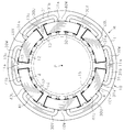
- the rotating electrical machine M as an electrical machine includes a stator 10 and a rotor 15 as a mover that is rotatably disposed inside the stator 10.
- the stator 10 includes an annular stator core 11, a plurality of fixed teeth 12 and a plurality of divided teeth 13 arranged along the circumferential direction on the radially inner side of the stator core 11, and a slot 14.
- the number of fixed teeth 12 and the number of divided teeth 13 are each 12, and the number of slots 14 is 24.
- the slots 14 are arranged at an equal pitch along the circumferential direction of the stator core 11.
- the stator core 11 is configured by laminating a plurality of core plates made of a magnetic material (steel plate) in the axial direction.
- a plurality of fixed teeth 12 are integrally formed on the inner peripheral surface of the stator core 11.
- the fixed teeth 12 are formed so as to extend in the radial direction of the stator core 11, that is, in the first direction from the inner peripheral surface of the stator core 11 toward the central axis P of the stator core 11.
- the fixed teeth 12 are formed so as to extend over the entire axial direction of the stator core 11.
- a locking projection 11 a is formed at an intermediate position between the fixed teeth 12 adjacent in the circumferential direction of the stator core 11 so as to extend over the entire axial direction of the stator core 11.
- the locking projection 11 a is formed in a tapered shape that gradually widens from the inner peripheral surface of the stator core 11 toward the central axis P (center portion) of the stator core 11.
- split teeth 13 are mounted between the fixed teeth 12 adjacent to each other in the circumferential direction of the stator core 11 on the radially inner side of the stator core 11.
- the divided teeth 13 have a rectangular plate shape, and the longitudinal dimension (dimension along the axial direction of the stator core 11) is the same as the axial dimension of the stator core 11.
- a locking recess 13 c is formed on the base end surface of the divided teeth 13 so as to extend over the entire longitudinal direction of the divided teeth 13.
- the locking recess 13c is formed in a tapered shape that gradually widens from the base end surface of the divided tooth 13 toward the front end surface.
- the divided teeth 13 are attached to the stator core 11 by fitting the engaging projections 11 a of the stator core 11 into the engaging recesses 13 c of the divided teeth 13. In this mounted state, the division teeth 13 are prevented from moving inward in the radial direction of the stator core 11 by the engagement of the engagement protrusions 11a with the engagement recesses 13c.
- a slot 14 having a rectangular shape in plan view is defined between the fixed teeth 12 and the divided teeth 13 that are adjacent to each other in the circumferential direction of the stator core 11.
- the U-phase, V-phase, and W-phase outer coils 30U, 30V, and 30W are wound around the fixed teeth 12 by distributed winding. There are two U-phase, V-phase, and W-phase outer coils 30U, 30V, and 30W, respectively.
- the outer coils 30U, 30V, and 30W are all arranged so as to be located on one circumference around the central axis P of the stator core 11. Each of the outer coils 30U, 30V, and 30W extends over the two fixed teeth 12 such that the outer coils 30U, 30V, and 30W straddle the two fixed teeth 12 with the one divided tooth 13 interposed therebetween. It is assembled. Further, coils of different phases are not inserted into the same slot 14.
- the pair of outer coils 30U are arranged with an angular interval of 180 degrees from each other, and are inserted into a total of four slots 14. There are eight slots 14 between the slot 14 in which one outer coil 30U is inserted and the slot 14 in which the other outer coil 30U is inserted.
- Each of the outer coil 30V and the outer coil 30W has the same arrangement as the outer coil 30U described above.
- Each of the outer coils 30U, 30V, and 30W is made of a coil wire (flat wire) having a rectangular cross section and a uniform width, and is covered with insulation.
- each of the outer coils 30U, 30V, and 30W (only the outer coil 30U is shown in FIG. 4A) includes a pair of insertion portions 37 that are inserted into the slots 14, and the stator core 11. And a pair of coil ends 31 (first coil ends) protruding from both end faces in the axial direction.
- each outer coil end 31 includes an outer transition portion 31b extending along the circumferential direction of the stator core 11 so as to connect the tips of the pair of bent portions 31a.
- Each outer coil end 31 is formed in a channel shape in plan view by a pair of bent portions 31a and an outer transition portion 31b.
- each outer transition portion 31 b is formed in a predetermined shape so as to extend along the circumferential direction of the stator core 11. Further, the outer crossover portion 31 b is disposed on the radially outer side of the stator core 11 with respect to the inner peripheral surface of the stator core 11 (corresponding to the bottom portion of the slot 14). In addition, when the insertion portion 37 is assembled in the slot 14, a portion that protrudes outward from both end surfaces of the stator core 11 in the axial direction is the outer coil end 31. As shown in FIG. 4A, an insulating sheet 32 made of synthetic resin is wound around each insertion portion 37.
- the U-phase, V-phase, and W-phase inner coils 40U, 40V, and 40W as the second series coils are wound around the fixed teeth 12 by distributed winding.
- the inner coils 40U, 40V, 40W are all arranged so as to be located on one circumference centered on the central axis P of the stator core 11.
- Each of the inner coils 40U, 40V, and 40W extends over the two fixed teeth 12 so as to straddle the two fixed teeth 12 with the one divided tooth 13 sandwiched between the two slots 14. It is assembled. Further, coils of different phases are not inserted into the same slot 14.
- the pair of inner coils 40U are arranged at an angular interval of 180 degrees from each other, and are inserted into a total of four slots 14.
- Each of the inner coil 40V and the inner coil 40W has the same arrangement as the inner coil 40U described above.
- Each of the inner coils 40U, 40V, and 40W is made of a coil wire (flat wire) having a rectangular cross section and a uniform width, and is covered with insulation.
- each of the inner coils 40U, 40V, 40W (only the inner coil 40U is shown in FIG. 4B) includes a pair of insertion portions 47 inserted into the slot 14 and the stator core 11. It has a pair of coil ends 41 (second coil ends) protruding from both end faces in the axial direction.
- each coil end 41 (hereinafter, referred to as an inner coil end 41) of each inner coil 40 ⁇ / b> U, 40 ⁇ / b> V, 40 ⁇ / b> W extends from both insertion portions 47 along the axial direction of the stator core 11.
- a pair of upright portions 41a is provided.
- the inner coil end 41 includes an inner transition portion 41b extending along the circumferential direction of the stator core 11 so as to connect the tips of the pair of standing portions 41a.
- Each inner coil end 41 is formed in a channel shape in a front view by a pair of upright portions 41a and an inner transition portion 41b.
- a synthetic resin insulating sheet 32 is wound around each insertion portion 47.
- the outer transition portion 31b is disposed outside the inner transition portion 41b in the radial direction of the stator core 11.
- the outer transition part 31b is disposed on the opposite side of the rotor 15 with respect to the inner transition part 41b.
- the outer transition part 31b is arranged on one first circumference centered on the central axis P of the stator core 11, and the inner transition part 41b is one second circle located radially inward of the first circumference. It is arranged on the circumference.
- the outer and inner coil insertion portions 37 and 47 are disposed on the second circumference.
- Each of the inner crossover portions 41b straddles the bent portions 31a of the two outer coils 30U adjacent to each other in the circumferential direction of the stator core 11.
- the teeth adjacent to each of the upright portions 41a between the pair of upright portions 41a of the inner coil ends 41 are the fixed teeth 12.
- the teeth over which both the outer transition portions 31b and the inner transition portions 41b that partially overlap with the outer transition portions 31b in the circumferential direction are the fixed teeth 12.
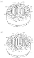
- the outer coils 30U, 30V, and 30W are incorporated into the stator core 11 before the inner coils 40U, 40V, and 40W.
- each outer coil 30U, 30V, 30W is assembled. That is, the outer coils 30U, 30V, and 30W are moved radially outward of the stator core 11.
- Each outer coil 30U, 30V, 30W is assembled
- two outer coils 30U, 30V, and 30W for each of the U phase, the V phase, and the W phase are arranged on the same circumference in the order of the U phase, the V phase, and the W phase along the circumferential direction of the stator core 11. Assemble to fixed teeth 12 (stator core 11).
- the divided teeth 13 are inserted into the gaps between the two outer coils 30 ⁇ / b> U, 30 ⁇ / b> V, 30 ⁇ / b> W adjacent in the circumferential direction of the stator core 11, and the divided teeth are inserted into the stator core 11. 13 is installed.
- the split teeth 13 are attached to the stator core 11 by fitting the locking recesses 13c of the split teeth 13 to the locking protrusions 11a of the stator core 11 while moving the split teeth 13 along the axial direction of the stator core 11. .
- the slots 14 are defined between the fixed teeth 12 and the divided teeth 13 that are adjacent in the circumferential direction of the stator core 11. Inserted portions 37 of the outer coils 30U, 30V, and 30W are inserted into the partitioned slots 14.
- the bent portion 31a of the outer coil end 31 extends from the insertion portion 37 (slot 14) toward the radially outer side of the stator core 11. For this reason, a gap is formed between the bent portions 31 a of the outer coil ends 31 adjacent to each other in the circumferential direction, and the locking projection 11 a is opened in the axial direction of the stator core 11 in the gap. That is, the bent portion 31 a does not exist on the extended line of the locking convex portion 11 a along the axial direction of the stator core 11. Therefore, the divided teeth 13 can be inserted while being moved along the axial direction of the stator core 11 between the two bent portions 31 a existing between the pair of fixed teeth 12.
- the inner coils 40U, 40V, and 40W are assembled to the two (paired) fixed teeth 12 with one divided tooth 13 interposed therebetween.
- the inner coils 40U, 40V, and 40W are assembled to the fixed teeth 12 over which both the inner transition portion 41b and the outer transition portion 31b are straddled.
- the inner coils 40U, 40V, 40W are moved from the inner space of the stator core 11 toward the radially outer side of the stator core 11, and a pair of fixed teeth 12 (and the same pair of fixed teeth 12) are fixed to the inner coils 40U, 40V, 40W.
- the inner coils 40U, 40V, and 40W are assembled to the same pair of fixed teeth 12 so that one divided tooth 13) between the teeth 12 is disposed.
- the outer transition part 31b is disposed radially outside the inner peripheral surface of the stator core 11 (corresponding to the bottom part of the slot 14), and a gap is formed between the pair of bent parts 31a at both ends of the transition part 31b. .
- the outer transition part 31b does not interfere with the assembly of the inner coils 40U, 40V, 40W.
- the insertion portion 37 is accommodated in the gap between the fixed teeth 12, and the inner transition portion 41b includes two bent portions 31a adjacent to each other in the circumferential direction of the stator core 11. It straddles and is arrange
- two inner coils 40U, 40V, and 40W for each of the U phase, the V phase, and the W phase are arranged on the same circumference (in the same series) in the order of the U phase, the V phase, and the W phase. Attach to the fixed teeth 12.
- the U-phase inner coil 40U and the V-phase inner coil 40V adjacent in the circumferential direction between the V-phase inner coil 40V and the W-phase inner coil 40W adjacent in the circumferential direction.
- a gap that allows the divided teeth 13 to be inserted is formed between each of the W-phase inner coil 40W and the U-phase inner coil 40U that are adjacent to each other in the circumferential direction.
- the divided teeth 13 are inserted into the gaps between the two inner coils 40 ⁇ / b> U, 40 ⁇ / b> V, 40 ⁇ / b> W adjacent in the circumferential direction of the stator core 11, and the divided teeth 13 are inserted into the stator core 11. Wear.
- the outer transition portion 31b is disposed on the radially outer side of the stator core 11 from the inner peripheral surface of the stator core 11, and is disposed on the radially outer side of the stator core 11 with respect to the locking convex portion 11a. Further, a gap opened in the axial direction of the stator core 11 is formed between the two bent portions 31 a arranged between the fixed teeth 12 adjacent in the circumferential direction. Therefore, the presence of the outer transition part 31b and the bent part 31a does not hinder the insertion of the divided teeth 13.
- the split teeth 13 are attached to the stator core 11 so that the insert portions 47 of the inner coils 40U, 40V, and 40W are sandwiched between the split teeth 13 and the fixed teeth 12.
- the split teeth 13 are mounted on the stator core 11 by fitting the latching recesses 13c of the split teeth 13 to the latching projections 11a of the stator core 11 while moving the split teeth 13 along the axial direction of the stator core 11. Is called.
- the slots 14 are partitioned between the fixed teeth 12 and the divided teeth 13 that are adjacent in the circumferential direction.
- An insertion portion 47 for inner coils 40U, 40V, and 40W is inserted into the slot 14.
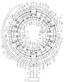
- FIG. 7 shows a wiring diagram of the outer coils 30U, 30V, 30W and the inner coils 40U, 40V, 40W in the stator 10 manufactured by the above method.
- the U-phase insertion part (shown by 37U in FIG. 7 only) of the pair of outer coils 30U connected to the U-phase terminal 51 of the inverter 50 is passed through a group of U-phase slots (shown by 14Uo in FIG. 7 only). ing.
- the V-phase insertion part (shown by 37V in FIG. 7 only) of the pair of outer coils 30V connected to the V-phase terminal 52 of the inverter 50 is passed through a group of V-phase slots (shown by 14V in FIG. 7 only). ing.
- a W-phase insertion portion (indicated by 37W in FIG. 7 only) of the pair of outer coils 30W connected to the W-phase terminal 53 of the inverter 50 is passed through a group of W-phase slots (indicated by 14W only in FIG. 7). ing.
- the U-phase insertion part (shown by 47U in FIG. 7 only) of the pair of inner coils 40U connected to the U-phase terminal 51 of the inverter 50 is passed through a group of U-phase slots (shown by 14Ui in FIG. 7 only).
- the V-phase insertion part (shown by 47V in FIG. 7 only) of the pair of inner coils 40V connected to the V-phase terminal 52 of the inverter 50 is passed through a group of V-phase slots (shown by 14Vi only in FIG. 7).
- a W-phase insertion portion (indicated by 47W in FIG. 7 only) of the pair of inner coils 40W connected to the W-phase terminal 53 of the inverter 50 is passed through a group of W-phase slots (indicated by 14Wi only in FIG. 7). ing.
- the U-phase outer coil 30U and the U-phase inner coil 40U are connected in series.
- As the U-phase coils the same number (two) of the first series of outer coils 30U and the second series of inner coils 40U are used.
- a V-phase outer coil 30V and a V-phase inner coil 40V are connected in series.
- As the V-phase coils the same number (two) of the first series of outer coils 30V and the second series of inner coils 40V are used.
- a W-phase outer coil 30W and a W-phase inner coil 40W are connected in series.
- As the W-phase coils the same number (two) of the first series of outer coils 30W and the second series of inner coils 40W are used.
- Reference numeral N1 is a neutral point where the outer coil 30U, 30V, 30W and the inner coil 40U, 40V, 40W end points of the coil wires 33, 34, 43 are connected
- reference numeral N2 is the outer coil 30U, 30V, This is a neutral point where the ends of the coil wires 35, 36 and 44 of 30W and the inner coils 40U, 40V and 40W are connected.
- the rotating electrical machine M is an 8-pole 3-phase 24-slot rotating electrical machine.
- the rotor 15 rotates by energizing the outer coils 30U, 30V, 30W and the inner coils 40U, 40V, 40W via the inverter 50.
- the above embodiment has the following advantages. (1) Preliminarily molded outer coils 30U, 30V, and 30W for U phase, V phase, and W phase are used, and premolded inner coils 40U, 40V, and 40W for U phase, V phase, and W phase, respectively. Is used.
- the outer coils 30U, 30V, and 30W are preliminarily molded such that each outer transition portion 31b is disposed radially outside the inner transition portion 41b of the inner coils 40U, 40V, and 40W. For this reason, when the inner coils 40U, 40V, 40W are assembled to the fixed teeth 12 after the outer coils 30U, 30V, 30W are assembled to the fixed teeth 12, the coil ends 31, 41 do not interfere with each other. .
- outer coils 30U, 30V, 30W and inner coils 40U, 40V, 40W with three-phase coils, and the three-phase coils are formed into separate shapes.
- tool can be reduced, and the manufacturing cost of the stator 10 can be held down.
- the U-phase, V-phase, and W-phase outer coils 30U, 30V, and 30W have their outer transition portions 31b (outer coil ends 31) on one circumference centered on the central axis P of the stator core 11.
- the outer coils 30U, 30V, and 30W are arranged in the same series.
- the U-phase, V-phase, and W-phase inner coils 40U, 40V, and 40W are arranged on one circumference with the inner transition portion 41b (inner coil end 41) centered on the central axis P of the stator core 11.
- the inner coils 40U, 40V, and 40W are arranged in the same series. Therefore, the outer coil end 31 and the inner coil end 41 can be reduced in size compared with the case where the coil ends of the three-phase coils are arranged on different circumferences.
- the U-phase outer coil 30U and the U-phase inner coil 40U, the V-phase outer coil 30V and the V-phase inner coil 40V, and the W-phase outer coil 30W and the W-phase inner coil 40U are Each is connected in series. Two outer coils 30U, 30V, and 30W are used, and two inner coils 40U, 40V, and 40W are used. For this reason, the coil length for every phase can be made the same, and the variation in the impedance of the coil between different phases can be suppressed. As a result, current imbalance can be made difficult to occur, and the occurrence of problems such as torque reduction, loss increase, and vibration increase due to power concentration can be prevented.
- the outer coils 30U, 30V, 30W are all formed in the same shape in the U phase, the V phase, and the W phase, and the inner coils 40U, 40V, 40W are also formed in the same shape in the U phase, the V phase, and the W phase. Is formed. For this reason, the outer coil ends 31 of the outer coils 30U, 30V, 30W arranged on the same circumference (in the same series) all have the same shape, and the inner coil 40U arranged on the same circumference (in the same series). , 40V, 40W all have the same shape. Therefore, the coil length for each phase can be made the same, and variation in the impedance of the coil between different phases can be suppressed. As a result, current imbalance can be made difficult to occur, and the occurrence of problems such as torque reduction, loss increase, and vibration increase due to power concentration can be prevented.
- the stator 10 includes a fixed tooth 12 integrally formed with the stator core 11 and a split tooth 13 that can be attached to and detached from the stator core 11. After the outer coils 30U, 30V, and 30W are assembled to the fixed teeth 12, a part of the divided teeth 12 is attached to the stator core 11 to define the slots 14, and the inner coils 40U, 40V, and 40W are assembled to the fixed teeth 12. After that, the remaining divided teeth 13 are attached to the stator core 11 to define the slots 14. Therefore, even when the distributed-winding stator 10 is manufactured, there is no need to deform the outer coils 30U, 30V, 30W and the inner coils 40U, 40V, 40W when they are assembled into the slots 14, and the coil wires are damaged. And the performance degradation of the rotating electrical machine M associated with the manufacture of the stator 10 can be prevented.
- Half of all the teeth are fixed teeth 12. Therefore, for example, compared with the case where all the teeth are divided into teeth 13, the time required to mount all the teeth on the stator core 11 can be shortened, the number of parts can be reduced, and the manufacturing cost of the stator 10 can be suppressed. . Furthermore, compared with the case where all the teeth are divided into teeth 13, an increase in iron loss due to the gap between the fitting portions between the divided teeth 13 and the stator core 11 can be reduced, and the stator core 11 is adjacent in the circumferential direction. Variations in the gap between the teeth can be suppressed, and as a result, an increase in torque ripple can be prevented.
- the amount of plastic deformation generated when all the divided teeth 13 are mounted on the stator core 11 is large, but in this embodiment, only half of all the teeth are included. Since the divided teeth 13, the amount of plastic deformation when the divided teeth 13 are assembled can be reduced to suppress the deterioration of electromagnetic characteristics.
- the first series of outer coils 30U, 30V, and 30W may have a shape in which the outer transition part 31b is disposed radially outside the inner transition part 41b (on the side opposite to the protruding direction of the fixed teeth 12). If it is not necessarily the same shape. For example, the length of a coil wire etc. may differ between different phases. Further, the inner coils 40U, 40V, 40W of each phase of the second series do not necessarily have the same shape as long as the inner connecting portion 41b has a shape straddling the bent portion 31a. The length or the like may be different.
- the first series coils are arranged so that at least two-phase coils (U phase and V phase, V phase and W phase, or W phase and U phase) are mixed, and the second series coil is at least two phases. (V phase and W phase, W phase and U phase, or U phase and V phase) may be arranged so as to coexist.
- the first series of coils are the first outer coils 301U, 301V, 301W and the second outer coils 302U, 302V arranged inside the first outer coils 301U, 301V, 301W in the radial direction of the stator core 11. , 302W.
- the second series of coils are the first inner coils 401U, 401V, 401W and the second inner coils 402U, 402V, 402W disposed inside the first inner coils 401U, 401V, 401W in the radial direction of the stator core 11. It consists of.
- All teeth may be fixed teeth 12, or all teeth may be divided teeth 13.
- a linear electric motor stator such as a linear motor may be configured as in the present invention.
- the outer coil first-series coil
- the inner coil is assembled to the stator core before the inner coil (second-series coil), and the transition part is more than the transition part of the inner coil.
- the coil arranged on the side opposite to the protruding direction of the teeth refers to the coil, and the inner coil is assembled to the stator core after the outer coil, and the connecting portion is closer to the protruding direction of the teeth than the connecting portion of the outer coil.
- M rotating electric machine as electric machine
- 10 stator
- 11 stator core
- 12 fixed teeth as teeth
- 13 divided teeth as teeth
- 14 slots
- 30U, 30V, 30W, 301U, 301V, 301W, 302U, 302V, 302W outer coil as first series coil
- 31 outer coil end as first series coil end
- 31a bent part
- 31b outer transition part
- 37 outer coil insertion part
- 41 ... inner coil end as a second series coil end
- 41b ... inner transition part, 47 ... Insertion part of the inner coil.
Landscapes
- Engineering & Computer Science (AREA)
- Power Engineering (AREA)
- Windings For Motors And Generators (AREA)
- Iron Core Of Rotating Electric Machines (AREA)
- Manufacture Of Motors, Generators (AREA)
Abstract
Priority Applications (4)
| Application Number | Priority Date | Filing Date | Title |
|---|---|---|---|
| EP10761627.8A EP2418757A4 (fr) | 2009-04-09 | 2010-03-30 | Stator dans une machine électrique |
| CN201080014398.4A CN102369651B (zh) | 2009-04-09 | 2010-03-30 | 电机的定子 |
| US13/256,679 US8704420B2 (en) | 2009-04-09 | 2010-03-30 | Stator for electric machine |
| KR1020117020859A KR101237250B1 (ko) | 2009-04-09 | 2010-03-30 | 전기 기계에 있어서의 스테이터 |
Applications Claiming Priority (2)
| Application Number | Priority Date | Filing Date | Title |
|---|---|---|---|
| JP2009-095158 | 2009-04-09 | ||
| JP2009095158A JP5446406B2 (ja) | 2009-04-09 | 2009-04-09 | 電機における固定子 |
Publications (1)
| Publication Number | Publication Date |
|---|---|
| WO2010116928A1 true WO2010116928A1 (fr) | 2010-10-14 |
Family
ID=42936213
Family Applications (1)
| Application Number | Title | Priority Date | Filing Date |
|---|---|---|---|
| PCT/JP2010/055736 WO2010116928A1 (fr) | 2009-04-09 | 2010-03-30 | Stator dans une machine électrique |
Country Status (6)
| Country | Link |
|---|---|
| US (1) | US8704420B2 (fr) |
| EP (1) | EP2418757A4 (fr) |
| JP (1) | JP5446406B2 (fr) |
| KR (1) | KR101237250B1 (fr) |
| CN (1) | CN102369651B (fr) |
| WO (1) | WO2010116928A1 (fr) |
Families Citing this family (15)
| Publication number | Priority date | Publication date | Assignee | Title |
|---|---|---|---|---|
| JP2013062897A (ja) * | 2011-09-12 | 2013-04-04 | Aida Engineering Ltd | インバータモータ装置 |
| JP5915736B2 (ja) * | 2012-06-01 | 2016-05-11 | 株式会社安川電機 | 回転電機、回転電機用ステータおよび車両 |
| JP5910738B2 (ja) * | 2012-06-01 | 2016-04-27 | 株式会社安川電機 | 回転電機、回転電機用ステータおよび車両 |
| JP6356394B2 (ja) * | 2013-08-07 | 2018-07-11 | 株式会社東芝 | 回転電機、及び回転電機の製造方法 |
| US9906105B1 (en) * | 2014-01-28 | 2018-02-27 | Maestra Energy, Llc | Electrical induction motor with reconfigured rotor mounted commutators for receiving an armature current from a stator mounted brush component along with a reversing gear arrangement for driving a pair of opposite gear rings |
| JP6248704B2 (ja) * | 2014-03-03 | 2017-12-20 | 株式会社豊田自動織機 | 車載用電動圧縮機 |
| DE102015225586A1 (de) * | 2015-12-17 | 2017-06-22 | Volkswagen Aktiengesellschaft | Spulenkörper für eine elektrische Spule |
| JP2017131046A (ja) * | 2016-01-21 | 2017-07-27 | 株式会社明電舎 | コイル及びこれを用いた回転電機の固定子 |
| JP6682956B2 (ja) * | 2016-03-30 | 2020-04-15 | アイシン精機株式会社 | モータ装置、およびモータ装置の製造方法 |
| CN105790479A (zh) * | 2016-04-05 | 2016-07-20 | 中国船舶重工集团公司第七〇二研究所 | 一种船舶推进电机及其定子线圈的绕制方法 |
| DE102017102314A1 (de) * | 2017-02-07 | 2018-08-09 | SciMo - Elektrische Hochleistungsantriebe GmbH | Wicklung einer elektrischen Maschine mit gesteigertem Füllgrad |
| JP7348029B2 (ja) * | 2019-10-31 | 2023-09-20 | ファナック株式会社 | ステータおよびモータ |
| JP7342654B2 (ja) * | 2019-11-26 | 2023-09-12 | 株式会社デンソー | 回転電機 |
| JP2023000667A (ja) * | 2021-06-18 | 2023-01-04 | 株式会社デンソー | モータ |
| WO2024087813A1 (fr) * | 2022-10-27 | 2024-05-02 | 安徽威灵汽车部件有限公司 | Stator, moteur électrique et véhicule |
Citations (6)
| Publication number | Priority date | Publication date | Assignee | Title |
|---|---|---|---|---|
| JPH06261475A (ja) * | 1993-03-08 | 1994-09-16 | Honda Motor Co Ltd | 電動機又は発電機のコア |
| JPH10271733A (ja) | 1997-03-27 | 1998-10-09 | Hitachi Ltd | 電動機およびステータの製造方法 |
| JP2003507994A (ja) * | 1999-08-16 | 2003-02-25 | アメリカン スーパーコンダクター コーポレイション | 電気モータの水冷ステータ巻線 |
| JP2005348461A (ja) * | 2004-05-31 | 2005-12-15 | Asahi Denki Kenkyusho:Kk | 整列巻きコイル及び整列巻きコイルの形成方法 |
| JP2006238687A (ja) * | 2005-01-28 | 2006-09-07 | Mosutetsuku:Kk | コイル、コイルユニット、ステーター、及びローター、コイル及びコイルユニット製造治具、並びに、コイル及びコイルユニット製造方法 |
| JP2007329985A (ja) * | 2006-06-06 | 2007-12-20 | Daikin Ind Ltd | アキシャルギャップ型モータおよびその製造方法 |
Family Cites Families (16)
| Publication number | Priority date | Publication date | Assignee | Title |
|---|---|---|---|---|
| US3495114A (en) * | 1968-06-14 | 1970-02-10 | Vasily Mikhailovich Kz | Cylindrical and disc stators for electrical machines having composite windings |
| JP3484006B2 (ja) * | 1996-01-30 | 2004-01-06 | 株式会社日立製作所 | 回転機および成形方法 |
| JPH10146030A (ja) * | 1996-11-05 | 1998-05-29 | Hitachi Ltd | 集中巻固定子を有する回転電機 |
| US6229241B1 (en) * | 1997-03-26 | 2001-05-08 | Hitachi, Ltd. | Structure and manufacturing method for motor and stator |
| JP2002125340A (ja) * | 1998-02-03 | 2002-04-26 | Hitachi Ltd | モータ、その製造方法およびそれに用いるインサータ |
| US7211919B2 (en) | 1999-08-16 | 2007-05-01 | American Superconductor Corporation | Thermally-conductive stator support structure |
| JP2005124362A (ja) * | 2003-10-20 | 2005-05-12 | Toyota Industries Corp | 巻き線用ケーブル及び電機子 |
| US7247967B2 (en) * | 2004-08-09 | 2007-07-24 | A. O. Smith Corporation | Electric motor having a stator |
| JP4678522B2 (ja) * | 2006-03-31 | 2011-04-27 | アイシン・エィ・ダブリュ株式会社 | ステータ及び回転電機 |
| JP5354888B2 (ja) * | 2007-11-05 | 2013-11-27 | 株式会社ミツバ | ブラシレスモータ |
| JP5253789B2 (ja) * | 2007-11-05 | 2013-07-31 | 株式会社ミツバ | ブラシレスモータ |
| JP2009189078A (ja) * | 2008-02-01 | 2009-08-20 | Toyota Industries Corp | 回転電機の固定子及び回転電機 |
| EP2112747B1 (fr) * | 2008-04-24 | 2014-01-22 | Magneti Marelli S.p.A. | Machine électrique et son procéde de fabrication |
| JP5235634B2 (ja) * | 2008-12-05 | 2013-07-10 | 日立オートモティブシステムズ株式会社 | 回転電機の製造方法 |
| EP2226923B1 (fr) * | 2009-03-03 | 2015-06-10 | GE Energy Power Conversion Technology Limited | Bobines |
| DE102009032883A1 (de) * | 2009-07-13 | 2011-01-27 | Siemens Aktiengesellschaft | Wickelkopfanordnung |
-
2009
- 2009-04-09 JP JP2009095158A patent/JP5446406B2/ja not_active Expired - Fee Related
-
2010
- 2010-03-30 EP EP10761627.8A patent/EP2418757A4/fr not_active Withdrawn
- 2010-03-30 US US13/256,679 patent/US8704420B2/en not_active Expired - Fee Related
- 2010-03-30 CN CN201080014398.4A patent/CN102369651B/zh not_active Expired - Fee Related
- 2010-03-30 WO PCT/JP2010/055736 patent/WO2010116928A1/fr active Application Filing
- 2010-03-30 KR KR1020117020859A patent/KR101237250B1/ko not_active IP Right Cessation
Patent Citations (6)
| Publication number | Priority date | Publication date | Assignee | Title |
|---|---|---|---|---|
| JPH06261475A (ja) * | 1993-03-08 | 1994-09-16 | Honda Motor Co Ltd | 電動機又は発電機のコア |
| JPH10271733A (ja) | 1997-03-27 | 1998-10-09 | Hitachi Ltd | 電動機およびステータの製造方法 |
| JP2003507994A (ja) * | 1999-08-16 | 2003-02-25 | アメリカン スーパーコンダクター コーポレイション | 電気モータの水冷ステータ巻線 |
| JP2005348461A (ja) * | 2004-05-31 | 2005-12-15 | Asahi Denki Kenkyusho:Kk | 整列巻きコイル及び整列巻きコイルの形成方法 |
| JP2006238687A (ja) * | 2005-01-28 | 2006-09-07 | Mosutetsuku:Kk | コイル、コイルユニット、ステーター、及びローター、コイル及びコイルユニット製造治具、並びに、コイル及びコイルユニット製造方法 |
| JP2007329985A (ja) * | 2006-06-06 | 2007-12-20 | Daikin Ind Ltd | アキシャルギャップ型モータおよびその製造方法 |
Also Published As
| Publication number | Publication date |
|---|---|
| EP2418757A4 (fr) | 2016-02-24 |
| CN102369651A (zh) | 2012-03-07 |
| KR101237250B1 (ko) | 2013-02-27 |
| EP2418757A1 (fr) | 2012-02-15 |
| JP2010246343A (ja) | 2010-10-28 |
| KR20110125233A (ko) | 2011-11-18 |
| CN102369651B (zh) | 2014-06-18 |
| JP5446406B2 (ja) | 2014-03-19 |
| US20120001513A1 (en) | 2012-01-05 |
| US8704420B2 (en) | 2014-04-22 |
Similar Documents
| Publication | Publication Date | Title |
|---|---|---|
| WO2010116928A1 (fr) | Stator dans une machine électrique | |
| JP6072238B2 (ja) | 回転電機の製造方法 | |
| WO2010087078A1 (fr) | Armature pour machine dynamo-électrique et son procédé de fabrication | |
| US7701107B2 (en) | Motor including a teeth section and a yoke section which are formed of mutually independent configuration members | |
| US11063482B2 (en) | Stator and motor having the same | |
| KR20120041127A (ko) | 고정자, 브러시리스 모터 및 이의 제조방법 | |
| EP3193428B1 (fr) | Stator | |
| JP5917109B2 (ja) | 端部絶縁部材、固定子および回転機 | |
| WO2011108736A1 (fr) | Stator et moteur | |
| US7893590B2 (en) | Stator having high assembly | |
| WO2017141361A1 (fr) | Machine électrique tournante et procédé de fabrication de machine électrique tournante | |
| WO2011121983A1 (fr) | Machine électrique tournante | |
| WO2015068266A1 (fr) | Stator pour machine électrique rotative, et machine électrique rotative | |
| CN108370184B (zh) | 旋转电机 | |
| JP2012095488A (ja) | 回転電機用ロータ、およびこれを用いた回転電機 | |
| CN106411014B (zh) | 旋转电机及其制造方法、定子线圈、线圈树脂结构体 | |
| JP2010246342A (ja) | 電機における固定子 | |
| JP2014072925A (ja) | 複数相のステータコイルの接続構造 | |
| JP2011004456A (ja) | モータ | |
| CN108781006B (zh) | 旋转电机、旋转电机的制造方法 | |
| JP2006115694A (ja) | 内転型電動機の固定子 | |
| JP2006081398A (ja) | 内転型電動機の固定子の製造方法 | |
| WO2019044612A1 (fr) | Moteur électrique | |
| JP2001251792A (ja) | 回転電機のステータコア | |
| WO2023149252A1 (fr) | Stator de machine électrique tournante, machine électrique tournante, procédé de fabrication de stator de machine électrique tournante et procédé de fabrication de machine électrique tournante |
Legal Events
| Date | Code | Title | Description |
|---|---|---|---|
| WWE | Wipo information: entry into national phase |
Ref document number: 201080014398.4 Country of ref document: CN |
|
| 121 | Ep: the epo has been informed by wipo that ep was designated in this application |
Ref document number: 10761627 Country of ref document: EP Kind code of ref document: A1 |
|
| DPE1 | Request for preliminary examination filed after expiration of 19th month from priority date (pct application filed from 20040101) | ||
| ENP | Entry into the national phase |
Ref document number: 20117020859 Country of ref document: KR Kind code of ref document: A |
|
| WWE | Wipo information: entry into national phase |
Ref document number: 13256679 Country of ref document: US |
|
| REEP | Request for entry into the european phase |
Ref document number: 2010761627 Country of ref document: EP |
|
| WWE | Wipo information: entry into national phase |
Ref document number: 2010761627 Country of ref document: EP |
|
| NENP | Non-entry into the national phase |
Ref country code: DE |