WO2010113449A1 - コンベア装置 - Google Patents
コンベア装置 Download PDFInfo
- Publication number
- WO2010113449A1 WO2010113449A1 PCT/JP2010/002184 JP2010002184W WO2010113449A1 WO 2010113449 A1 WO2010113449 A1 WO 2010113449A1 JP 2010002184 W JP2010002184 W JP 2010002184W WO 2010113449 A1 WO2010113449 A1 WO 2010113449A1
- Authority
- WO
- WIPO (PCT)
- Prior art keywords
- articles
- detector
- conveyor
- position information
- main conveyor
- Prior art date
- Legal status (The legal status is an assumption and is not a legal conclusion. Google has not performed a legal analysis and makes no representation as to the accuracy of the status listed.)
- Ceased
Links
Images

Classifications
-
- B—PERFORMING OPERATIONS; TRANSPORTING
- B65—CONVEYING; PACKING; STORING; HANDLING THIN OR FILAMENTARY MATERIAL
- B65G—TRANSPORT OR STORAGE DEVICES, e.g. CONVEYORS FOR LOADING OR TIPPING, SHOP CONVEYOR SYSTEMS OR PNEUMATIC TUBE CONVEYORS
- B65G1/00—Storing articles, individually or in orderly arrangement, in warehouses or magazines
- B65G1/02—Storage devices
- B65G1/04—Storage devices mechanical
- B65G1/137—Storage devices mechanical with arrangements or automatic control means for selecting which articles are to be removed
-
- B—PERFORMING OPERATIONS; TRANSPORTING
- B65—CONVEYING; PACKING; STORING; HANDLING THIN OR FILAMENTARY MATERIAL
- B65G—TRANSPORT OR STORAGE DEVICES, e.g. CONVEYORS FOR LOADING OR TIPPING, SHOP CONVEYOR SYSTEMS OR PNEUMATIC TUBE CONVEYORS
- B65G43/00—Control devices, e.g. for safety, warning or fault-correcting
- B65G43/08—Control devices operated by article or material being fed, conveyed or discharged
-
- B—PERFORMING OPERATIONS; TRANSPORTING
- B65—CONVEYING; PACKING; STORING; HANDLING THIN OR FILAMENTARY MATERIAL
- B65G—TRANSPORT OR STORAGE DEVICES, e.g. CONVEYORS FOR LOADING OR TIPPING, SHOP CONVEYOR SYSTEMS OR PNEUMATIC TUBE CONVEYORS
- B65G47/00—Article or material-handling devices associated with conveyors; Methods employing such devices
- B65G47/52—Devices for transferring articles or materials between conveyors i.e. discharging or feeding devices
-
- G—PHYSICS
- G06—COMPUTING OR CALCULATING; COUNTING
- G06M—COUNTING MECHANISMS; COUNTING OF OBJECTS NOT OTHERWISE PROVIDED FOR
- G06M7/00—Counting of objects carried by a conveyor
- G06M7/02—Counting of objects carried by a conveyor wherein objects ahead of the sensing element are separated to produce a distinct gap between successive objects
- G06M7/04—Counting of piece goods, e.g. of boxes
Definitions
- the present invention relates to a conveyor device, and more particularly, to a conveyor device in which a branch path is connected to a main conveyor and is manually sorted.
- the conveyor device is, for example, a belt conveyor, and mainly includes a main conveyor (main line) and a plurality of branch paths (chutes) branched therefrom.
- Articles are put into the main conveyor and sorted into each branch path.
- this sorting method there is a method using an automatic sorting machine.
- manual sorting is performed for articles that are not subject to automatic sorting (unstandardized articles that cannot be automatically discriminated, broken articles, and articles packed with valuables).
- a manual sorting conveyor device such a conveyor device is referred to as a manual sorting conveyor device.
- a detector is provided on each branch path.
- Each detector is a photoelectric sensor or a limit switch.
- As the photoelectric sensor a transmission type, a mirror reflection type, and a diffuse reflection type are used.
- the detector detects ON / OFF when the article passes, and the control unit counts it as the number of sorting.
- the count number is displayed on a sorting number monitor provided in each branch path. Thereby, sorting performance management, progress management, productivity management, and the like are performed.
- the detector counts less than the actual number of sorting.
- the detector detects more than the actual number of sorting.
- the stagnation of the article occurs in the branch path, such as when the branch path is full or clogged, the detector remains in the ON state. That is, the detector cannot detect the article normally.
- An object of the present invention is to accurately count the number of articles sorted into a branch path in a conveyor device having a branch path.
- a conveyor device is a conveyor device for conveying a plurality of articles, and includes a main conveyor, a branch path, a first detector and a second detector, and a calculation unit. Yes.
- the main conveyor is a device for conveying a plurality of articles.
- the branch path is branched from the branch point of the main conveyor.
- a 1st detector and a 2nd detector are each provided in the conveyance direction upstream and downstream of the branching point of a branching path, and detect the articles
- the calculation unit calculates the number of articles sorted into the branch path from the difference between the number of articles detected by the first detector and the number of articles detected by the second detector.
- the article is conveyed by the main conveyor and detected by the first detector. Further, the operator sorts the articles into branch paths as necessary. Articles not sorted into the branch path are further conveyed by the main conveyor and detected by the second detector.
- the calculation unit calculates the number of articles sorted into the branch path from the difference between the number of articles detected by the first detector and the number of articles detected by the second detector. In this apparatus, since the first detector and the second detector detect the number of articles conveyed by the main conveyor, the state of the articles in the branch path does not affect the detector. Therefore, in the manual sorting conveyor device having a branch path, the number of articles sorted into the branch path can be accurately counted.
- the interval adjustment device appropriately adjusts the conveyance interval of the articles conveyed on the main conveyor.
- a display unit for displaying the number of articles sorted into the branch path may be further provided.
- the movement amount acquisition unit for obtaining the movement amount of the main conveyor is further provided, and the calculation unit is configured to estimate the estimated positions of the articles detected by the first detector and the second detector based on the movement amount of the main conveyor.
- the difference between the number of articles detected by the first detector and the number of articles detected by the second detector may be determined based on the comparison result.
- the difference between the number of articles detected by the first detector and the number of articles detected by the second detector is equal to the estimated positions of the articles detected by the first detector and the second detector. Determined by comparison. That is, it can be seen that the articles determined to be absent by the comparison there are sorted into the branch roads. In this way, the number of articles sorted into the branch path can be obtained in real time.
- the number of articles sorted into the branch path cannot be obtained accurately in real time.
- “the number of articles sorted in real time can be obtained” means that the number of articles sorted during the sorting operation can be obtained. For example, this means that the number of articles in a sorted state can be obtained 5 to 10 seconds after actually being sorted into a branch path. In other words, it is possible to prevent fluctuations in the number of branches, for example, a situation in which articles that are detected by the first detector and are not detected by the second detector are not counted in the branch path.
- the difference between the number of articles detected by the first detector and the number of articles detected by the second detector is the estimated position of the article detected by the first detector and the article detected by the second detector.
- the estimated position may be on the downstream side in the transport direction with respect to the second detector.
- a conveyor apparatus is an apparatus for conveying a plurality of articles, and includes a main conveyor, a plurality of branch paths, a plurality of detectors, and a calculation unit.
- the main conveyor conveys a plurality of articles.
- the plurality of branch paths are branched from a plurality of branch points of the main conveyor.
- Each of the plurality of detectors is provided on the upstream side or the downstream side in the conveyance direction of the branch point, and detects an article on the main conveyor. Based on the difference in the number of articles detected by a pair of adjacent detectors arranged upstream and downstream in the conveyance direction of one branch point among the plurality of branch points, the calculation unit The number of sorted items is calculated.
- an article is conveyed by the main conveyor and detected by a detector on the upstream side in the conveyance direction of each branch point. Further, the operator sorts the articles into branch paths as necessary. Articles that are not sorted into the branch path are further transported by the main conveyor, and are detected by a detector on the downstream side of the branch point in the transport direction.
- the calculation unit calculates the number of articles sorted into the branch path from the difference between the numbers of articles detected by the pair of detectors. In this apparatus, since a pair of detectors detect an article conveyed by the main conveyor, the state of the article on the branch path does not affect the detector. Therefore, in the manual sorting conveyor device having a branch path, the number of articles sorted into the branch path can be accurately counted.
- one detector serves as both the upstream detector function and the downstream detector function.
- the number of vessels can be reduced.
- a device for adjusting the intervals on the main conveyor of a plurality of articles arranged upstream of the most upstream branch point in the transport direction may be further provided.
- a plurality of display units each displaying the number of articles sorted into a plurality of branch paths may be further provided.
- the difference between the number of articles detected by a pair of adjacent detectors is determined based on a mismatch between the estimated positions of the articles detected by the pair of adjacent detectors, and the estimated positions are determined by a pair of adjacent detectors.
- the downstream side in the transport direction may be more than the detector on the downstream side in the transport direction.
- a conveyor apparatus is an apparatus for transporting a plurality of articles, and includes a main conveyor, a branch path, a first detector and a second detector, and a calculation unit. ing.
- the main conveyor conveys articles.
- the branch path is branched from the branch point of the main conveyor.
- a 1st detector and a 2nd detector are each provided in the conveyance direction upstream and downstream of a branch point, and detect the articles
- the calculation unit calculates the number of articles sorted into the branch path.
- the calculation unit includes first estimated position information obtained when the article detected by the first detector is on the downstream side in the transport direction from the second detector, obtained based on the amount of movement of the main conveyor, and the second detector
- first estimated position information obtained when the article detected by the first detector is on the downstream side in the transport direction from the second detector, obtained based on the amount of movement of the main conveyor, and the second detector
- the second estimated position information corresponding to the first estimated position information does not exist when the article detected by is compared with the second estimated position information when the article is downstream in the transport direction from the second detector. It is determined that the article is branched into the branch path.
- the article is first transported by the main conveyor and detected by the first detector. Further, the operator sorts the articles into branch paths as necessary. Articles not sorted into the branch path are further conveyed by the main conveyor and detected by the second detector.
- the calculation unit calculates the number of articles sorted into the branch path.
- the calculation unit determines that the article is branched on the branch path when there is no second estimated position information corresponding to the first estimated position information. In this way, the number of articles sorted into the branch path can be obtained in real time. For this reason, it is useful for work progress confirmation. If the difference between the detection number of the first detector and the detection number of the second detector is simply taken, the influence of the number of articles conveyed between the first detector and the second detector on the main conveyor. Therefore, the number of articles sorted into the branch path cannot be obtained accurately in real time.
- a device for adjusting the interval on the main conveyor of a plurality of articles, which is arranged on the upstream side in the conveyance direction from the branch point, may further be provided.
- a first memory for storing the first estimated position information and a second memory for storing the second estimated position information are further provided, and the calculation unit compares the contents of the first memory with the contents of the second memory to The first estimated position information and the second estimated position information may be compared.
- the calculation unit can obtain the number of articles sorted into the branch path in real time by comparing the contents of the first memory and the contents of the second memory. For this reason, it is useful for work progress confirmation.
- the first memory and the second memory have the same number of bits corresponding to a predetermined distance downstream from the second detector in the transport direction
- the calculation unit stores the first estimated position information of the article in the first memory, and shifts the stored first estimated position information according to the movement amount of the main conveyor
- the calculation unit stores the second estimated position information of the article in the second memory and shifts the stored second estimated position information according to the movement amount of the main conveyor
- the calculation unit may determine whether there is second estimated position information corresponding to the first estimated position information by comparing corresponding bits of the first memory and the second memory.
- the calculation unit stores the information about the article in the memory and shifts the information about the article according to the movement amount of the main conveyor. Therefore, the calculation unit can always compare the presence of the article between the first memory and the second memory. In this way, the number of articles sorted into the branch path can be obtained in real time. For this reason, it is useful for work progress confirmation.
- a display unit for displaying the number of articles sorted into the branch path may be further provided.
- the conveyor device can accurately count the number of articles sorted into the branch path.
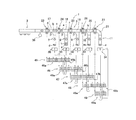
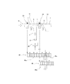
- the schematic diagram of the conveyor apparatus as one Example of this invention It is the elements on larger scale of Drawing 1, and is a figure for explaining operation which computes the number of articles branched to the 1st branch way using the 1st detector and the 2nd detector.
- the block diagram which shows the control structure of the conveyor apparatus as one Example of this invention.
- FIG. 1 is a schematic diagram of a conveyor apparatus as an embodiment of the present invention.
- the conveyor device 1 is a manual sorting conveyor device for an operator to sort a plurality of articles according to a specific standard while conveying a plurality of articles from the upstream side toward the downstream side.
- the conveyor apparatus 1 mainly includes a charging conveyor 3, a main conveyor 5, and a plurality of branch paths (7, 8, 9, 10, 11).
- the input conveyor 3 is, for example, a belt conveyor, and is a conveyor for an operator to input articles. Note that a robot may throw in an article instead of an operator.
- the main conveyor 5 is a conveyor for automatically conveying articles.
- the main conveyor 5 is, for example, a belt conveyor.
- the main conveyor 5 is provided continuously with the charging conveyor 3 and extends in a straight line in this embodiment.
- the input conveyor 3 and the main conveyor 5 have separate drive motors (not shown), so that they are driven by the first conveyor drive mechanism 41 and the second conveyor drive mechanism 43 (FIG. 3). It has become.
- a plurality of branch paths (7, 8, 9, 10, 11) are branched from the main conveyor 5.
- the branch path (7, 8, 9, 10, 11) is, for example, a roller conveyor, and the plurality of branch paths (7, 8, 9, 10, 11) are a plurality of branch points on the main conveyor 5 ( 17, 18, 19, 20, 21). More specifically, the conveyance surface of the branch path (7, 8, 9, 10, 11) is inclined so as to become lower as the distance from the main conveyor 5 increases, and the article is conveyed in the branch path by its own weight. In the vicinity of each branch point, an operator waits, identifies an article conveyed by the main conveyor 5, and pulls in an article corresponding to the branch path he is in charge of.
- the first branch path 7 branches from the first branch point 17
- the second branch path 8 branches from the second branch point 18
- the third branch path 9 Branching from the third branch point 19
- the fourth branch path 10 branches from the fourth branch point 20
- the fifth branch path 11 branches from the fifth branch point 21.
- the conveyor apparatus 1 further has a plurality of detectors (23, 24, 25, 26, 27).
- the plurality of detectors (23, 24, 25, 26, 27) are devices for detecting the number of articles passed by the main conveyor 5.
- the plurality of detectors (23, 24, 25, 26, 27) are provided along the main conveyor 5, and are arranged at positions where detection errors due to the operation of the sorting operator are unlikely to occur.
- the plurality of detectors are transmissive photoelectric sensors including a pair of projectors and light receivers, but may be other types of photoelectric sensors or limit switches.
- a first detector 23 is provided on the upstream side of the main conveyor 5 on the upstream side of the first branch point 17, on the downstream side of the first branch point 17 and on the upstream side of the second branch point 18.
- a second detector 24 is provided, a third detector 25 is provided downstream of the second branch point 18 and upstream of the third branch point 19, and downstream of the third branch point 19 and fourth branch.
- a fourth detector 26 is provided upstream of the point 20, and a fifth detector 27 is provided downstream of the fourth branch point 20 and upstream of the fifth branch point 21.
- the conveyor apparatus 1 further has a plurality of sorting number monitors (30, 31, 32, 33, 34).
- the plurality of sorting number monitors (30, 31, 32, 33, 34) is a device for indicating in real time the number of articles divided into the branch paths (7, 8, 9, 10, 11) (described later). .
- a first sorting number monitor 30 is disposed corresponding to the first branch path 7
- a second sorting number monitor 31 is disposed corresponding to the second branch path 8, and corresponds to the third branch path 9.
- the third sorting number monitor 32 is arranged
- the fourth sorting number monitor 33 is arranged corresponding to the fourth branch path 10
- the fifth sorting number monitor 34 is arranged corresponding to the fifth branch path 11. Yes.
- the conveyor apparatus 1 further includes a rotary encoder 36.
- the rotary encoder 36 is a device for detecting the conveyance speed of the main conveyor 5.
- FIG. 3 is a block diagram showing a control configuration of the conveyor apparatus as one embodiment of the present invention.
- the control unit 37 is a computer having a CPU, a RAM, and a ROM, and performs a control operation by executing a predetermined program.
- the control unit 37 includes a detection information processing unit 51, a movement amount determination unit 52, and a memory 39.
- the movement amount determination unit 52 determines the movement amount of the main conveyor 5 based on a signal from the rotary encoder 36.
- the first detector 23, the second detector 24, the third detector 25, the fourth detector 26, and the fifth detector 27 are connected to the control unit 37, and the detection signals from them are controlled. Is transmitted to the unit 37.
- the control unit 37 further includes a first conveyor drive mechanism 41, a second conveyor drive mechanism 43, a first sort number monitor 30, a second sort number monitor 31, a third sort number monitor 32, a fourth sort number monitor 33, A fifth sorting number monitor 34 is connected to which a control signal is transmitted from the control unit 37.
- FIG. 2 is a partially enlarged view of FIG. 1 and is a diagram for explaining an operation of calculating the number of articles branched into the first branch using the first detector and the second detector.
- the plurality of position information storage units (45, 46, 47, 48, 49) are devices for storing in real time the conveyance positions of the articles detected by the detectors (23, 24, 25, 26, 27). (See below). Specifically, a first position information storage unit 45 is prepared corresponding to the first detector 23, a second position information storage unit 46 is disposed corresponding to the second detector 24, and the third detector 25. The third position information storage unit 47 is arranged corresponding to the fourth detector 26, the fourth position information storage unit 48 is arranged corresponding to the fourth detector 26, and the fifth position information storage unit corresponding to the fifth detector 27 is arranged. 49 are prepared.
- the plurality of position information storage units include a first memory portion that stores position information of articles between the corresponding detector and the downstream detector in the main conveyor 5; And a second memory part for storing position information of articles between the downstream detector and the further downstream detector.
- the fifth position information storage unit 49 has only the first memory portion.
- the first memory portion and the second memory portion have a plurality of bits. In this embodiment, the first memory portion has 12 bits and the second memory portion also has 12 bits. When each bit is “0”, it means that the article does not exist, and when it is “1”, it means that the article exists.
- the first position information storage unit 45 includes a first memory portion 45a and a second memory portion 45b.
- the first memory portion 45a corresponds to the distance between the first detector 23 and the second detector 24, and the second memory portion 45b is the distance between the second detector 24 and the third detector 25. It corresponds to.
- the second position information storage unit 46 includes a first memory portion 46a and a second memory portion 46b.
- the first memory portion 46a corresponds to the distance between the second detector 24 and the third detector 25, and the second memory portion 46b is the distance between the third detector 25 and the fourth detector 26. It corresponds to.
- the third position information storage unit 47 includes a first memory portion 47a and a second memory portion 47b.
- the first memory portion 47a corresponds to the distance between the third detector 25 and the fourth detector 26, and the second memory portion 47b is the distance between the fourth detector 26 and the fifth detector 27. It corresponds to.
- the fourth position information storage unit 48 includes a first memory portion 48a and a second memory portion 48b.
- the first memory portion 48 a corresponds to the distance between the fourth detector 26 and the fifth detector 27, and the second memory portion 48 b corresponds to the distance to a predetermined position downstream from the fifth detector 27. ing.
- the fifth position information storage unit 49 has only the first memory portion 49a.
- the first memory portion 49 a corresponds to the distance to a predetermined position downstream from the fifth detector 27.
- the second memory portion 45b of the first position information storage unit 45 and the first memory portion 46a of the second position information storage unit 46 correspond to each other.
- the second memory portion 46 b corresponds to the first memory portion 47 a of the third position information storage unit 47
- the second memory portion 47 b of the third position information storage unit 47 corresponds to the first position of the fourth position information storage unit 48.
- the second memory portion 48b of the fourth position information storage unit 48 and the first memory portion 49a of the fifth position information storage unit 49 correspond to the memory portion 48a.
- Branching route sorting number counting operation of conveyor device When an input operator inputs an article into the input conveyor 3, the input conveyor 3 and the main conveyor 5 convey the article. The conveyance interval of articles conveyed by the main conveyor 5 is appropriately adjusted by the input conveyor 3. Therefore, the detectors (23, 24, 25, 26, 27) can accurately detect the number of articles. As a result, the number of articles sorted into the branch path can be accurately obtained. The sorting worker sorts the articles to be sorted into his or her branch at the branch point. The article is detected on the main conveyor 5 by a detector (23, 24, 25, 26, 27).
- the detection information processing unit 51 of the control unit 37 subtracts the number of detections of the second detector 24 from the number of detections of the first detector 23 to thereby calculate the number of articles sorted into the first branch path 7. calculate.
- the detection information processing unit 51 calculates the number of articles sorted in the second branch path 8 by subtracting the detection number of the third detector 25 from the detection number of the second detector 24.
- the detection information processing unit 51 calculates the number of articles sorted into the third branch path 9 by subtracting the detection number of the fourth detector 26 from the detection number of the third detector 25.
- the detection information processing unit 51 calculates the number of articles sorted into the fourth branch path 10 by subtracting the detection number of the fifth detector 27 from the detection number of the fourth detector 26.
- the detection information processing unit 51 calculates the number of articles sorted into the fifth branch path 11 from the number detected by the fifth detector 27. In this case, since the detector (23, 24, 25, 26, 27) detects an article conveyed on the main conveyor 5, the state of the article in the branch path (7, 8, 9, 10, 11) is determined. It does not adversely affect the detectors (23, 24, 25, 26, 27). Therefore, in the manual sorting conveyor device having a branch path, the number of articles sorted into the branch path can be accurately detected.
- the detection information processing unit 51 counts the number of sorting in the branch path as follows and displays the number of sorting on the sorting number monitor in real time.
- the detection information processing unit 51 changes the first bit from “0” to “1” in the first position information storage unit 45. In FIG. 1, “1” is indicated by hatching.
- the movement amount determination unit 52 calculates the movement amount using the speed information of the main conveyor 5 from the rotary encoder 36, and transmits the obtained movement amount to the detection information processing unit 51.
- the detection information processing unit 51 shifts “1” in the first position information storage unit 45 based on the movement amount of the main conveyor 5.
- “1” in the first position information storage unit 45 corresponds to the position of the article on the main conveyor 5. This operation is similarly performed in the second position information storage unit 46, the third position information storage unit 47, the fourth position information storage unit 48, and the fifth position information storage unit 49.
- alphabets are attached to the actual articles in the conveyor device 1, and the corresponding article alphabet is also attached to “1” (shaded part) indicated in the information storage unit. However, information on the actual article itself is not stored in the information storage unit.
- the detection information processing unit 51 compares the second memory portion 45 b of the first position information storage unit 45 with the first memory portion 46 a of the second position information storage unit 46. Specifically, the detection information processing unit 51 compares the two for each bit. In this case, three bits are “1” in the former, whereas two bits are “1” in the latter, so that the number of the former is increased by one. This means that one of the articles that have passed through the first detector 23 is sorted at the first branch point 17. Therefore, the detected information processing unit 51 displays the sorting number “1” on the first sorting number monitor 30. The timing at which the detection information processing unit 51 compares the memories and adds the number to the first sorting number monitor 30 is performed at regular time intervals.
- the certain time is, for example, the time for the article to move from the detector to the detector.
- the detection information processing unit 51 always performs comparison between the memories, and uses the first bit of the second memory portion 45b of the first position information storage unit 45 and the first memory portion 46a of the second position information storage unit 46.
- a number may be added to the first sorting number monitor 30, and comparison between memories is always performed. The number may be added to the first sorting number monitor 30 when the above state is found by comparison of subsequent bits (for example, the second bit to the fifth bit).
- the same information is displayed on the second sort number monitor 31, the third sort number monitor 32, and the fourth sort number monitor 33.
- the detection information processing unit 51 when the detection information processing unit 51 receives the detection signal from the fifth detector 27, the detection information processing unit 51 changes the display of the fifth sorting number monitor 34 without comparing the memories.
- the conveyor device 1 displays the number of articles sorted in real time on the sorting number monitor. For this reason, it is useful for work progress confirmation.
- the conveyor device 1 is a device for conveying a plurality of articles, and includes a main conveyor 5, a first branch path 7, a first detector 23 and a second detector 24, and a detection information processing unit 51. ing.
- the main conveyor 5 is a device for conveying a plurality of articles.
- the first branch path 7 is branched from the first branch point 17 of the main conveyor 5.
- the first detector 23 and the second detector 24 are provided on the upstream side and the downstream side in the transport direction of the first branch point 17, respectively, and detect articles on the main conveyor 5.
- the detection information processing unit 51 calculates the number of articles sorted into the first branch path 7 from the difference between the number of articles detected by the first detector 23 and the number of articles detected by the second detector 24. calculate.
- the article is conveyed by the main conveyor 5 and detected by the first detector 23. Further, the operator sorts the articles into the first branch path 7 as necessary. Articles not sorted into the first branch path 7 are further conveyed by the main conveyor 5 and detected by the second detector 24.
- the detection information processing unit 51 calculates the number of articles sorted into the first branch path 7 from the difference between the number of articles detected by the first detector 23 and the number of articles detected by the second detector 24. calculate.
- the state of the article in the first branch path 7 does not affect the detector. Therefore, in the manual sorting conveyor device having a branch path, the number of articles sorted into the branch path can be accurately counted.
- a rotary encoder 36 for obtaining the amount of movement of the main conveyor is further provided, and the detection information processing unit 51 is detected by the first detector 23 and the second detector 24 based on the amount of movement of the main conveyor 5, respectively.
- the difference between the number of articles detected by the first detector 23 and the number of articles detected by the second detector 24 may be determined based on the comparison result.
- the difference between the number of articles detected by the first detector 23 and the number of articles detected by the second detector 24 is the same as that detected by the first detector 23 and the second detector 24.
- the number of articles sorted into the first branch path 7 can be obtained in real time. For this reason, it is useful for work progress confirmation.
- the main conveyor 5 is transported between the first detector 23 and the second detector 24 simply by taking the difference between the number detected by the first detector 23 and the number detected by the second detector 24. Since the influence of the number of articles cannot be removed, the number of articles sorted into the first branch path 23 cannot be obtained accurately in real time.
- “the number of articles sorted in real time can be obtained” means that the number of articles sorted during the sorting operation can be obtained. For example, this means that the number of articles in a sorted state can be obtained 5 to 10 seconds after actually being sorted into a branch path.
- the fluctuation of the number of branches for example, the number of articles detected by the first detector 23 and not detected by the second detector 24 but not branched to the first branch path 7 is counted as the number of branches. The situation can be prevented.
- the conveyor device 1 further includes a charging conveyor 3 on the main conveyor 5 on the upstream side in the transport direction from the first branch point 17. Since the input conveyor 3 has a lower conveying speed than the main conveyor 5, the articles that are close to each other on the input conveyor 3 are separated from each other when being transferred to the main conveyor 5, and are conveyed in a state where a constant interval is maintained. In this way, the input conveyor 3 adjusts the article conveyance interval. In this apparatus, the conveyance interval of the articles conveyed by the main conveyor 5 is appropriately adjusted by the input conveyor 3. Therefore, the first detector 23 and the second detector 24 can accurately count the number of articles. As a result, the number of articles sorted into the first branch path 7 can be accurately obtained.
- the conveyor apparatus 1 is demonstrated from the other viewpoint of this invention.
- the conveyor device 1 is a device for conveying a plurality of articles, and includes a main conveyor 5, a first branch path 7, a first detector 23 and a second detector 24, and a detection information processing unit 51.
- the main conveyor 5 conveys articles.
- the first branch path 7 is branched from the first branch point 17 of the main conveyor 5.
- the first detector 23 and the second detector 24 are provided on the upstream side and the downstream side in the transport direction of the first branch point 17, respectively, and detect articles on the main conveyor 5.
- the detection information processing unit 51 calculates the number of articles sorted into the first branch path 7.
- the detection information processing unit 51 obtains the first estimated position information when the article detected by the first detector 23 is on the downstream side in the transport direction from the second detector 24, obtained based on the amount of movement of the main conveyor 5. And the second estimated position information corresponding to the first estimated position information by comparing the article detected by the second detector 24 with the second estimated position information when the article is downstream of the second detector 24 in the transport direction. When the information does not exist, it is determined that the article is branched to the first branch path 7. In this apparatus, the article is conveyed by the main conveyor 5 and detected by the first detector 23. Further, the operator sorts the articles into the first branch path 7 as necessary. Articles not sorted into the first branch path 7 are further conveyed by the main conveyor 5 and detected by the second detector 24.
- the detection information processing unit 51 calculates the number of articles sorted into the first branch path 7.
- the detection information processing unit 51 determines that the article is branched to the first branch path 7 when the second estimated position information corresponding to the first estimated position information does not exist. In this way, the number of articles sorted into the first branch path 7 can be obtained in real time. For this reason, it is useful for work progress confirmation. If the difference between the detection number of the first detector 23 and the detection number of the second detector 24 is simply taken, the main conveyor 5 is transported between the first detector 23 and the second detector 24. Since the influence of the number of articles cannot be removed, the number of articles sorted into the first branch path 7 cannot be obtained accurately in real time.
- the conveyor apparatus 1 includes a second memory portion 45b of a first position information storage unit 45 that stores first estimated position information, and a first memory portion 46a of a second position information storage unit 46 that stores second estimated position information.
- the detected information processing unit 51 compares the first estimated position information and the second estimated position by comparing the second memory portion 45b of the first position information storage unit 45 with the first memory portion 46a of the second position information storage unit 46. Compare with information.
- the detection information processing unit 51 can obtain the number of articles sorted into the first branch path 7 in real time. For this reason, it is useful for work progress confirmation.
- the second memory portion 45b of the first position information storage unit 45 and the first memory portion 46a of the second position information storage unit 46 have the same number corresponding to a predetermined distance downstream from the second detector 24 in the transport direction. It has multiple bits.
- the detection information processing unit 51 stores the first estimated position information of the article in the second memory portion 45b of the first position information storage unit 45, and stores the first estimation stored according to the movement amount of the main conveyor 5. Shift position information.
- the detection information processing unit 51 stores the second estimated position information of the article in the first memory portion 46a of the second position information storage unit 46, and stores the second estimated information stored in accordance with the movement amount of the main conveyor 5. Shift position information.
- the detected information processing unit 51 compares the corresponding bits of the second memory portion 45b of the first position information storage unit 45 and the first memory portion 46a of the second position information storage unit 46, thereby obtaining first estimated position information. It is determined whether there is second estimated position information corresponding to.
- the detected information processing unit 51 stores the detected article information in a memory and shifts the article information according to the amount of movement of the main conveyor 5. Therefore, the detection information processing unit 51 can always confirm the presence of the article by comparing the second memory portion 45b of the first position information storage unit 45 with the first memory portion 46a of the second position information storage unit 46. . In this way, the number of articles sorted into the first branch path 7 can be obtained in real time. For this reason, it is useful for work progress confirmation.
- the sorting number monitor may indicate the ratio of the total number of articles, not the number of branched articles. For example, when 25, 100, 75, 100, and 100 are sorted, 6.25%, 25%, 18.75%, 25%, 25%, and 25% are displayed. As a result, even if an error occurs in the detector and the total number becomes an inaccurate number, the ratio of the articles sorted into the individual branch paths to the whole can be obtained in real time. In this way, the tendency of the branching of the articles can be understood, which is effective for progress management.
- the plurality of branch paths are branched from the main conveyor, but the number of branch paths may be one. In the embodiment, the plurality of branch paths extend only to one side of the main conveyor, but may be arranged to extend to both sides.
- the branch path is not limited to the roller conveyor.
- the branch path may be a belt conveyor or a simple ramp.
- the shape and arrangement of the main conveyor are not limited to the above embodiment.
- Article conveyance interval adjusting means is not limited to the input conveyor.
- a stopper that prohibits and permits the movement of the article may be disposed on the main conveyor so that the article is conveyed to the main conveyor at regular intervals.
- Means for obtaining the amount of movement of the main conveyor is not limited to the rotary encoder.
- a linear encoder that directly detects the amount of movement of the main conveyor may be used.
- articles are sorted manually, but the present invention can also be applied to a conveyor device that performs automatic sorting by a machine.
- the description has mainly focused on counting the number of articles sorted.
- the above-described function can also be used to check whether or not articles are reliably sorted into a branch path.
- the number of articles sorted into the branch path is displayed on the display device in the conveyor device.
- the number of articles may be transmitted to the management device via the network.
- the present invention can be widely applied to a conveyor device in which a branch path is connected to the main conveyor and performs a sorting operation.
Landscapes
- Engineering & Computer Science (AREA)
- Mechanical Engineering (AREA)
- Physics & Mathematics (AREA)
- General Physics & Mathematics (AREA)
- Theoretical Computer Science (AREA)
- Control Of Conveyors (AREA)
- Branching, Merging, And Special Transfer Between Conveyors (AREA)
- Warehouses Or Storage Devices (AREA)
Abstract
Description
第1に、作業者が複数の物品をくっついた状態で分岐路に引き込むと、検出器は実際の仕分け数より少なくカウントする。
第2に、作業者が検出器の検出に影響を与えるような動作(例えば、手で検出器を遮光する)を行うと、検出器は実際の仕分け数より多く検出する。
第3に、分岐路が満杯になったり荷詰まりを起こしたりするなど物品の滞留が分岐路で生じると、検出器はON状態が続く。つまり、検出器は物品を正常に検出できない。
本発明の一見地に係るコンベア装置は、複数の物品を搬送するためのコンベア装置であって、主コンベアと、分岐路と、第1検出器および第2検出器と、算出部とを備えている。主コンベアは、複数の物品を搬送するための装置である。分岐路は、主コンベアの分岐点から分岐されている。第1検出器および第2検出器は、分岐路の分岐点の搬送方向上流側および下流側にそれぞれ設けられ、主コンベア上の物品を検出する。算出部は、第1検出器によって検出された物品の数と第2検出器によって検出された物品の数との差から、分岐路に仕分けられた物品の数を算出する。
この装置では、物品は、主コンベアによって搬送されて、第1検出器によって検出される。さらに、作業者が必要に応じて物品を分岐路に仕分ける。分岐路に仕分けられなかった物品は、主コンベアによってさらに搬送され、第2検出器によって検出される。算出部は、第1検出器によって検出された物品の数と第2検出器によって検出された物品の数との差から、分岐路に仕分けられた物品の数を算出する。
この装置では、第1検出器および第2検出器が検出するのは主コンベアによって搬送される物品の数なので、分岐路における物品の状態が検出器に影響を与えることはない。したがって、分岐路を有する手仕分けコンベア装置において、分岐路に仕分けられた物品の数を正確にカウントすることができる。
この場合、最初に、間隔調整装置によって、主コンベアを搬送される物品の搬送間隔が適切に調整される。
この装置では、第1検出器によって検出された物品の数と第2検出器によって検出された物品の数との差は、第1検出器および第2検出器において検出された物品の推定位置同士の比較によって決定される。つまり、そこでの比較によって無いと判断された物品は分岐路に仕分けられたことが分かる。このようにして、分岐路に仕分けられた物品の数をリアルタイムに得ることができる。このため、作業進捗確認に有用である。なお、単に第1検出器による検出数と第2検出器による検出数との差を取るだけでは、主コンベアにおいて2つの検出器の間を搬送されている物品の数の影響を取り除くことができないので、分岐路へ仕分けられた物品の数をリアルタイムで正確に得ることができない。
なお、ここでいう「リアルタイムに仕分けられた物品の数を得ることができる」とは、仕分け作業の途中に仕分けられた物品の数を得ることができることを意味する。例えば、実際に分岐路に仕分けられてから5~10秒後に仕分け状態の物品の数を得ることができることを意味する。言い換えれば、分岐数のふらつき、例えば、第1検出器で検出されて第2検出器で検出されていない物品のうち分岐路に分岐されていないものまで分岐数にカウントされる事態を防止できる。
この装置では、物品は、主コンベアによって搬送されて、各分岐点の搬送方向上流側にある検出器によって検出される。さらに、作業者が必要に応じて物品を分岐路に仕分ける。分岐路に仕分けられなかった物品は、主コンベアによってさらに搬送され、分岐点の搬送方向下流側にある検出器によって検出される。算出部は、一対の検出器によって検出された物品の数同士の差から、分岐路に仕分けられた物品の数を算出する。
この装置では、一対の検出器が検出するのは主コンベアによって搬送される物品なので、分岐路における物品の状態が検出器に影響を与えることはない。したがって、分岐路を有する手仕分けコンベア装置において、分岐路に仕分けられた物品の数を正確にカウントすることができる。
この装置では、物品は、最初に、主コンベアによって搬送されて、第1検出器によって検出される。さらに、作業者が必要に応じて物品を分岐路に仕分ける。分岐路に仕分けられなかった物品は、主コンベアによってさらに搬送され、第2検出器によって検出される。算出部は、分岐路に仕分けられた物品の数を算出する。
この装置では、算出部は、第1推定位置情報に対応する第2推定位置情報が存在しない場合に、当該物品は分岐路に分岐されていると判断する。このようにして、分岐路に仕分けられた物品の数をリアルタイムに得ることができる。このため、作業進捗確認に有用である。なお、単に第1検出器の検出数と第2検出器の検出数の差を取ることにすると、主コンベアにおいて第1検出器と第2検出器の間を搬送されている物品の数の影響を取り除くことができないので、分岐路に仕分けられた物品の数をリアルタイムで正確に得ることができない。
この装置では、算出部は第1メモリの内容と第2メモリの内容を比較することで、分岐路に仕分けられた物品の数をリアルタイムで得ることができる。このため、作業進捗確認に有用である。
算出部は、第1メモリにおいて、物品の第1推定位置情報を記憶すると共に、主コンベアの移動量に応じて、記憶された第1推定位置情報をシフトさせ、
算出部は、第2メモリにおいて、物品の第2推定位置情報を記憶すると共に、主コンベアの移動量に応じて、記憶された第2推定位置情報をシフトさせ、
算出部は、第1メモリと第2メモリの対応ビット同士を比較することで第1推定位置情報に対応する第2推定位置情報が存在するか否かを判断してもよい。
この装置では、算出部は、物品の情報をメモリに記憶すると共に、主コンベアの移動量に応じて物品の情報をシフトさせている。したがって、算出部は常に物品の存在を第1メモリと第2メモリとで比較できる。このようにして、分岐路に仕分けられた物品の数をリアルタイムで得ることができる。このため、作業進捗確認に有用である。
図1を用いて、コンベア装置1を説明する。図1は、本発明の一実施例としてのコンベア装置の模式図である。
投入コンベア3および主コンベア5はそれぞれ別個の駆動用モータ(図示せず)を有しており、それらは第1コンベア駆動機構41および第2コンベア駆動機構43(図3)によって駆動されるようになっている。
より詳細には、分岐路(7、8、9、10、11)の搬送面は、主コンベア5から離れるに従って低くなるように傾斜しており、物品は自重によって分岐路内を搬送される。
各分岐点の近くには、作業者が待機して、主コンベア5によって搬送される物品を識別し、自分が担当の分岐路に対応する物品を引き込む。
より詳細には、上流側から、第1分岐路7が第1分岐点17から分岐しており、第2分岐路8が第2分岐点18から分岐しており、第3分岐路9が第3分岐点19から分岐しており、第4分岐路10が第4分岐点20から分岐しており、第5分岐路11が第5分岐点21から分岐している。
この実施例では、複数の検出器は、一対の投光器および受光器からなる透過型の光電センサであるが、他の種類の光電センサであってもよいし、リミットスイッチでもよい。
具体的には、主コンベア5の上流側から、第1分岐点17の上流側に第1検出器23が設けられ、第1分岐点17の下流側でかつ第2分岐点18の上流側に第2検出器24が設けられ、第2分岐点18の下流側でかつ第3分岐点19の上流側に第3検出器25が設けられ、第3分岐点19の下流側でかつ第4分岐点20の上流側に第4検出器26が設けられ、第4分岐点20の下流側でかつ第5分岐点21の上流側に第5検出器27が設けられている。
図3を用いて、コンベア装置1の制御構成を説明する。図3は、本発明の一実施例としてのコンベア装置の制御構成を示すブロック図である。
メモリ39は、図1および図2に示すように、複数の位置情報記憶部(45、46、47、48、49)を有している。図2は、図1の部分拡大図であり、第1検出器と第2検出器を用いて第1分岐路に分岐された物品の数を算出する動作を説明するための図である。複数の位置情報記憶部(45、46、47、48、49)は、検出器(23、24、25、26、27)によって検出された物品の搬送位置をリアルタイムで記憶するための装置である(後述)。
具体的には、第1検出器23に対応して第1位置情報記憶部45が用意され、第2検出器24に対応して第2位置情報記憶部46が配置され、第3検出器25に対応して第3位置情報記憶部47が配置され、第4検出器26に対応して第4位置情報記憶部48が配置され、第5検出器27に対応して第5位置情報記憶部49が用意されている。
第1メモリ部分と第2メモリ部分は複数のビットを有している。この実施例では、第1メモリ部分は12ビット有しており、第2メモリ部分も12ビット有している。各ビットが「0」の場合は物品が存在しないことを意味しており、「1」の場合は物品が存在することを意味している。
投入作業者が物品を投入コンベア3に投入すると、投入コンベア3および主コンベア5が物品を搬送する。投入コンベア3によって、主コンベア5によって搬送される物品の搬送間隔が適切に調整される。したがって、検出器(23、24、25、26、27)が物品の数を正確に検出できる。この結果、分岐路に仕分けられた物品の数が正確に得られる。
仕分け作業者は、分岐点において自分の担当の分岐路に仕分けられるべき物品を仕分けていく。物品は、主コンベア5上で検出器(23、24、25、26、27)によって通過を検出される。
この装置では、制御部37の検出情報処理部51は、第1検出器23の検出数から第2検出器24の検出数を引くことで、第1分岐路7に仕分けられた物品の数を算出する。検出情報処理部51は、第2検出器24の検出数から第3検出器25の検出数を引くことで、第2分岐路8に仕分けられた物品の数を算出する。検出情報処理部51は、第3検出器25の検出数から第4検出器26の検出数を引くことで、第3分岐路9に仕分けられた物品の数を算出する。検出情報処理部51は、第4検出器26の検出数から第5検出器27の検出数を引くことで、第4分岐路10に仕分けられた物品の数を算出する。検出情報処理部51は、第5検出器27の検出数から、第5分岐路11に仕分けられた物品の数を算出する。
この場合、検出器(23、24、25、26、27)が検出するのは主コンベア5上を搬送される物品なので、分岐路(7、8、9、10、11)における物品の状態が検出器(23、24、25、26、27)に悪影響を与えることはない。したがって、分岐路を有する手仕分けコンベア装置において、分岐路に仕分けられた物品の数を正確に検出することができる。
物品が通過して第1検出器23がON/OFFされると、検出情報処理部51は第1位置情報記憶部45において、第1ビットを「0」から「1」にする。図1において、「1」は斜線で示されている。その後、移動量判定部52は、ロータリエンコーダ36からの主コンベア5の速度情報を用いて移動量を算出し、得られた移動量を検出情報処理部51に送信する。検出情報処理部51は、主コンベア5の移動量に基づいて、第1位置情報記憶部45において「1」をシフトさせていく。したがって、第1位置情報記憶部45において「1」は、物品の主コンベア5上の位置に対応している。なお、この動作は、第2位置情報記憶部46、第3位置情報記憶部47、第4位置情報記憶部48、第5位置情報記憶部49でも同様に行われる。
なお、検出情報処理部51がメモリ同士の比較を行って第1仕分け数モニタ30に数を追加するタイミングは、一定時間間隔で行われる。一定時間とは、例えば、物品が検出器から検出器までの間を移動する時間である。また、検出情報処理部51は、メモリ同士の比較を常に行って、第1位置情報記憶部45の第2メモリ部分45bと第2位置情報記憶部46の第1メモリ部分46aの第1ビットで前者が「1」になっているのに後者が「0」になっていることが判明した時に、第1仕分け数モニタ30に数を追加してもよいし、メモリ同士の比較を常に行って、後のビット(例えば、第2ビット~第5ビット)の比較で上記状態が判明した時に、第1仕分け数モニタ30に数を追加してもよい。
コンベア装置1について、特徴部分を説明する。なお、ここでは、第1分岐路7に仕分けられる物品の数の計測についてのみ説明する。
コンベア装置1は複数の物品を搬送するための装置であって、主コンベア5と、第1分岐路7と、第1検出器23および第2検出器24と、検出情報処理部51とを備えている。主コンベア5は、複数の物品を搬送するための装置である。第1分岐路7は、主コンベア5の第1分岐点17から分岐されている。第1検出器23および第2検出器24は、第1分岐点17の搬送方向上流側および下流側にそれぞれ設けられ、主コンベア5上の物品を検出する。検出情報処理部51は、第1検出器23によって検出された物品の数と第2検出器24によって検出された物品の数との差から、第1分岐路7に仕分けられた物品の数を算出する。
この装置では、物品は、主コンベア5によって搬送されて、第1検出器23によって検出される。さらに、作業者が必要に応じて物品を第1分岐路7に仕分ける。第1分岐路7に仕分けられなかった物品は、主コンベア5によってさらに搬送され、第2検出器24によって検出される。検出情報処理部51は、第1検出器23によって検出された物品の数と第2検出器24によって検出された物品の数との差から、第1分岐路7に仕分けられた物品の数を算出する。
この場合、第1検出器23および第2検出器24が検出するのは主コンベア5上を搬送される物品なので、第1分岐路7における物品の状態が検出器に影響を与えることはない。したがって、分岐路を有する手仕分けコンベア装置において、分岐路に仕分けられた物品の数を正確にカウントすることができる。
この装置では、第1検出器23によって検出された物品の数と第2検出器24によって検出された物品の数との差は、第1検出器23および第2検出器24において検出された物品の推定位置同士の比較によって決定される。つまり、そこでの比較によって無いと判断された物品は第1分岐路7に仕分けられたことが分かる。このようにして、第1分岐路7に仕分けられた物品の数をリアルタイムに得ることができる。このため、作業進捗確認に有用である。なお、単に第1検出器23による検出数と第2検出器24による検出数との差を取るだけでは、主コンベア5において第1検出器23と第2検出器24の間を搬送されている物品の数の影響を取り除くことができないので、第1分岐路23へ仕分けられた物品の数をリアルタイムで正確に得ることができない。
なお、ここでいう「リアルタイムに仕分けられた物品の数を得ることができる」とは、仕分け作業の途中に仕分けられた物品の数を得ることができることを意味する。例えば、実際に分岐路に仕分けられてから5~10秒後に仕分け状態の物品の数を得ることができることを意味する。言い換えれば、分岐数のふらつき、例えば、第1検出器23で検出されて第2検出器24で検出されていない物品のうち第1分岐路7に分岐されていないものまで分岐数にカウントされる事態を防止できる。
この装置では、投入コンベア3によって、主コンベア5によって搬送される物品の搬送間隔が適切に調整される。したがって、第1検出器23および第2検出器24が物品の数を正確にカウントできる。この結果、第1分岐路7に仕分けられた物品の数が正確に得られる。
コンベア装置1は、複数の物品を搬送するための装置であって、主コンベア5と、第1分岐路7と、第1検出器23および第2検出器24と、検出情報処理部51とを備えている。主コンベア5は、物品を搬送する。第1分岐路7は、主コンベア5の第1分岐点17から分岐されている。第1検出器23および第2検出器24は、第1分岐点17の搬送方向上流側および下流側にそれぞれ設けられ、主コンベア5上の物品を検出する。検出情報処理部51は、第1分岐路7に仕分けられた物品の数を算出する。検出情報処理部51は、主コンベア5の移動量に基づいて得られた、第1検出器23によって検出された物品が第2検出器24より搬送方向下流側にあるときの第1推定位置情報と、第2検出器24によって検出された物品が第2検出器24より搬送方向下流側にあるときの第2推定位置情報とを比較して、第1推定位置情報に対応する第2推定位置情報が存在しない場合に、当該物品は第1分岐路7に分岐されていると判断する。
この装置では、物品は、主コンベア5によって搬送されて、第1検出器23によって検出される。さらに、作業者が必要に応じて物品を第1分岐路7に仕分ける。第1分岐路7に仕分けられなかった物品は、主コンベア5によってさらに搬送され、第2検出器24によって検出される。検出情報処理部51は、第1分岐路7に仕分けられた物品の数を算出する。
この装置では、検出情報処理部51は、第1推定位置情報に対応する第2推定位置情報が存在しない場合に、当該物品は第1分岐路7に分岐されていると判断する。このようにして、第1分岐路7に仕分けられた物品の数をリアルタイムに得ることができる。このため、作業進捗確認に有用である。なお、単に第1検出器23の検出数と第2検出器24の検出数の差を取ることにすると、主コンベア5において第1検出器23と第2検出器24の間を搬送されている物品の数の影響を取り除くことができないので、第1分岐路7に仕分けられた物品の数をリアルタイムで正確に得ることができない。
この装置では、検出情報処理部51は、第1分岐路7に仕分けられた物品の数をリアルタイムで得ることができる。このため、作業進捗確認に有用である。
この装置では、検出情報処理部51は、検出された物品の情報をメモリに記憶すると共に、主コンベア5の移動量に応じて物品の情報をシフトさせている。したがって、検出情報処理部51は、第1位置情報記憶部45の第2メモリ部分45bと、第2位置情報記憶部46の第1メモリ部分46aとで比較して、物品の存在を常に確認できる。このようにして、第1分岐路7に仕分けられた物品の数をリアルタイムで得ることができる。このため、作業進捗確認に有用である。
以上、本発明の一実施形態について説明したが、本発明は上記実施形態に限定されるものではなく、発明の要旨を逸脱しない範囲で種々の変更が可能である。特に、本明細書に書かれた複数の実施形態および変形例は必要に応じて任意に組合せ可能である。
前記実施形態では複数の分岐路が主コンベアの片側にのみ延びていたが、両側に延びるように配置されていてもよい。
主コンベアの形状や配置は前記実施形態に限定されない。
主コンベアの移動量を得るための手段はロータリエンコーダに限定されない。例えば、主コンベアの移動量を直接検出するリニアエンコーダを用いてもよい。
前記実施形態では主に仕分けられた物品の数量のカウントを中心に説明したが、上記の機能は物品が分岐路に確実に仕分けられたか否かの確認にも用いることができる。
前記実施形態では分岐路に仕分けられた物品の数はコンベア装置内の表示装置に表示されていたが、前述の物品の数はネットワークによって管理装置に送信されてもよい。
3 投入コンベア(物品の搬送間隔調整装置)
5 主コンベア
7 第1分岐路
8 第2分岐路
9 第3分岐路
10 第4分岐路
11 第5分岐路
17 第1分岐点
18 第2分岐点
19 第3分岐点
20 第4分岐点
21 第5分岐点
23 第1検出器
24 第2検出器
25 第3検出器
26 第4検出器
27 第5検出器
30 第1仕分け数モニタ
31 第2仕分け数モニタ
32 第3仕分け数モニタ
33 第4仕分け数モニタ
34 第5仕分け数モニタ
36 ロータリエンコーダ(移動量取得部)
37 制御部
39 メモリ
41 第1コンベア駆動機構
43 第2コンベア駆動機構
45 第1位置情報記憶部
45a 第1メモリ部分
45b 第2メモリ部分(第1メモリ)
46 第2位置情報記憶部
46a 第1メモリ部分(第2メモリ)
46b 第2メモリ部分(第1メモリ)
47 第3位置情報記憶部
47a 第1メモリ部分(第2メモリ)
47b 第2メモリ部分(第1メモリ)
48 第4位置情報記憶部
48a 第1メモリ部分(第2メモリ)
48b 第2メモリ部分(第1メモリ)
49 第5位置情報記憶部
49a 第1メモリ部分(第2メモリ)
51 検出情報処理部(算出部)
52 移動量判定部(移動量取得部)
Claims (15)
- 複数の物品を搬送するためのコンベア装置であって、
前記複数の物品を搬送するための主コンベアと、
前記主コンベアの分岐点から分岐された分岐路と、
前記分岐路の前記分岐点の搬送方向上流側および下流側にそれぞれ設けられ、前記主コンベア上の前記物品を検出するための第1検出器および第2検出器と、
前記第1検出器によって検出された前記物品の数と前記第2検出器によって検出された前記物品の数との差から、前記分岐路に仕分けられた物品の数を算出する算出部と、
を備えたコンベア装置。 - 前記分岐点より搬送方向上流側に配置された、前記複数の物品の前記主コンベア上の間隔を調整するための装置をさらに備えている、請求項1に記載のコンベア装置。
- 前記分岐路に仕分けられた物品の数を表示する表示部をさらに備えている、請求項1に記載のコンベア装置。
- 前記主コンベアの移動量を得るための移動量取得部をさらに備え、
前記算出部は、前記主コンベアの前記移動量に基づいて、前記第1検出器および前記第2検出器においてそれぞれ検出された物品の推定位置を比較して、前記第1検出器によって検出された物品の数と前記第2検出器によって検出された物品の数の差は比較結果に基づいて決定される、請求項1に記載のコンベア装置。 - 前記第1検出器によって検出された物品の数と前記第2検出器によって検出された物品の数の差は、前記第1検出器によって検出された物品の推定位置と、前記第2検出器によって検出された物品の推定位置との不一致に基づいて決定され、前記推定位置は前記第2検出器より搬送方向下流側である、請求項4に記載のコンベア装置。
- 複数の物品を搬送するためのコンベア装置であって、
前記複数の物品を搬送するための主コンベアと、
前記主コンベアの複数の分岐点から分岐された複数の分岐路と、
各々が前記分岐点の搬送方向上流側または下流側に設けられ、前記主コンベア上の物品を検出するための複数の検出器と、
前記複数の分岐点のうちの1つの分岐点の搬送方向上流側と下流側に配置された隣接する一対の検出器によって検出された物品の数の差に基づいて、各分岐路に仕分けられた物品の数を算出する算出部と、
を備えたコンベア装置。 - 最上流の分岐点より搬送方向上流側に配置された、前記複数の物品の前記主コンベア上の間隔を調整するための装置をさらに備えた、請求項5に記載のコンベア装置。
- 前記複数の分岐路に仕分けられた物品の数をそれぞれ表示する複数の表示部をさらに備えている、請求項5に記載のコンベア装置。
- 前記主コンベアの移動量を得るための移動量取得部をさらに備え、
前記算出部は、前記主コンベアの前記移動量に基づいて、前記一対の隣接する検出器によってそれぞれ検出された物品の推定位置を比較して、前記一対の隣接する検出器によって検出された物品の数同士の差は比較結果に基づいて決定される、請求項5に記載のコンベア装置。 - 前記一対の隣接する検出器によって検出された物品の数同士の差は、前記一対の隣接する検出器によって検出された物品の推定位置同士の不一致に基づいて決定され、前記推定位置は前記一対の隣接する検出器のうち搬送方向下流側の検出器より搬送方向下流側である、請求項9に記載のコンベア装置。
- 複数の物品を搬送するためのコンベア装置であって、
前記物品を搬送するための主コンベアと、
前記主コンベアの分岐点から分岐された分岐路と、
前記分岐点の搬送方向上流側および下流側にそれぞれ設けられ、前記主コンベア上の前記物品を検出するための第1検出器および第2検出器と、
前記分岐路に仕分けられた物品の数を算出するための算出部とを備え、
前記算出部は、前記主コンベアの移動量に基づいて得られた、前記1検出器によって検出された物品が前記第2検出器より搬送方向下流側にあるときの第1推定位置情報と、前記第2検出器によって検出された物品が前記第2検出器より搬送方向下流側にあるときのときの第2推定位置情報とを比較して、前記第1推定位置情報に対応する前記第2推定位置情報が存在しない場合に、当該物品は前記分岐路に分岐されていると判断する、コンベア装置。 - 前記分岐点より搬送方向上流側に配置された、前記複数の物品の前記主コンベア上の間隔を調整するための装置をさらに備えている、請求項11に記載のコンベア装置。
- 前記分岐路に仕分けられた物品の数を表示する表示部をさらに備えている、請求項11に記載のコンベア装置。
- 前記第1推定位置情報を記憶する第1メモリと、前記第2推定位置情報を記憶する第2メモリとをさらに備え、
前記算出部は、前記第1メモリの内容と前記第2メモリの内容を比較することで前記第1推定位置情報と前記第2推定位置情報とを比較する、請求項11に記載のコンベア装置。 - 前記第1メモリと前記第2メモリは、前記第2検出器から搬送方向下流側の所定の距離に対応する同数の複数ビットを有しており、
前記算出部は、前記第1メモリにおいて、物品の第1推定位置情報を記憶すると共に、前記主コンベアの移動量に応じて、記憶された前記第1推定位置情報をシフトさせ、
前記算出部は、前記第2メモリにおいて、物品の第2推定位置情報を記憶すると共に、前記主コンベアの移動量に応じて、記憶された前記第2推定位置情報をシフトさせ、
前記算出部は、前記第1メモリと前記第2メモリの対応ビット同士を比較することで前記第1推定位置情報に対応する前記第2推定位置情報が存在するか否かを判断する、請求項14に記載のコンベア装置。
Priority Applications (5)
| Application Number | Priority Date | Filing Date | Title |
|---|---|---|---|
| US13/262,280 US8499920B2 (en) | 2009-04-03 | 2010-03-26 | Conveyor device |
| KR1020117025064A KR101351494B1 (ko) | 2009-04-03 | 2010-03-26 | 컨베이어 장치 |
| HK12107842.1A HK1167128B (en) | 2009-04-03 | 2010-03-26 | Conveyor device |
| CN201080014406.5A CN102369149B (zh) | 2009-04-03 | 2010-03-26 | 输送装置 |
| JP2011507003A JP5397465B2 (ja) | 2009-04-03 | 2010-03-26 | コンベア装置 |
Applications Claiming Priority (2)
| Application Number | Priority Date | Filing Date | Title |
|---|---|---|---|
| JP2009-090619 | 2009-04-03 | ||
| JP2009090619 | 2009-04-03 |
Publications (1)
| Publication Number | Publication Date |
|---|---|
| WO2010113449A1 true WO2010113449A1 (ja) | 2010-10-07 |
Family
ID=42827760
Family Applications (1)
| Application Number | Title | Priority Date | Filing Date |
|---|---|---|---|
| PCT/JP2010/002184 Ceased WO2010113449A1 (ja) | 2009-04-03 | 2010-03-26 | コンベア装置 |
Country Status (5)
| Country | Link |
|---|---|
| US (1) | US8499920B2 (ja) |
| JP (1) | JP5397465B2 (ja) |
| KR (1) | KR101351494B1 (ja) |
| CN (1) | CN102369149B (ja) |
| WO (1) | WO2010113449A1 (ja) |
Families Citing this family (17)
| Publication number | Priority date | Publication date | Assignee | Title |
|---|---|---|---|---|
| KR20140022569A (ko) * | 2012-08-14 | 2014-02-25 | 한국전자통신연구원 | 소포 자동화 기기 |
| JP6011311B2 (ja) * | 2012-12-18 | 2016-10-19 | 日本電気硝子株式会社 | ワーク搬送装置およびワーク搬送方法 |
| JP6487649B2 (ja) * | 2014-08-08 | 2019-03-20 | 株式会社イシダ | 検査振分システム |
| US10135737B2 (en) * | 2014-09-30 | 2018-11-20 | Nicira, Inc. | Distributed load balancing systems |
| US10322883B2 (en) * | 2014-11-18 | 2019-06-18 | Itoh Denki Co. | Conveyor device, conveyor system, zone controller, CAD device, and method for manufacturing conveyor device |
| CN104555386B (zh) * | 2014-12-12 | 2018-10-19 | 云南财经大学 | 一种平面动态在线柔性合单系统 |
| CN104986485A (zh) * | 2014-12-27 | 2015-10-21 | 孙涛 | 一种药片输送分配系统 |
| CN104787569B (zh) * | 2015-04-20 | 2017-05-10 | 南京我乐家居股份有限公司 | 板材自动化生产线 |
| CN104773432B (zh) * | 2015-04-20 | 2017-05-10 | 南京我乐家居股份有限公司 | 板材生产线自动出入库装置和方法 |
| FR3044648B1 (fr) * | 2015-12-04 | 2018-01-12 | Fives Intralogistics S.A. | Installation de tri d'articles comprenant un systeme de detection et d'analyse de la trajectoire des articles et procede de tri |
| CN107176433B (zh) * | 2016-03-09 | 2020-07-17 | 顺丰科技有限公司 | 物品传送辅助系统 |
| US10421613B2 (en) * | 2018-02-23 | 2019-09-24 | Grabit, Inc. | Electroadhesive tilt sorter and control system |
| EP3950545A4 (en) | 2019-04-05 | 2022-12-28 | Itoh Denki Co., Ltd. | CONVEYING SYSTEM, CAUSE INFORMATION REPORTING DEVICE, CAUSE INFORMATION REPORTING DEVICE PROGRAM, AND COMPUTER READABLE RECORDING MEDIA WITH CAUSE INFORMATION REPORTING DEVICE RECORDED PROGRAM |
| CN110386394B (zh) * | 2019-08-09 | 2022-09-30 | 佛山井松智能科技有限公司 | 一种自动化立体仓库的智能输送系统 |
| JP7149607B2 (ja) | 2019-10-25 | 2022-10-07 | 伊東電機株式会社 | コンベヤシステム |
| JP7335621B2 (ja) * | 2020-05-19 | 2023-08-30 | 株式会社ヤハタホールディングス | 搬送システム |
| CN113716120A (zh) * | 2021-09-29 | 2021-11-30 | 红云红河烟草(集团)有限责任公司 | 一种烟条输送带堵塞报警装置 |
Citations (3)
| Publication number | Priority date | Publication date | Assignee | Title |
|---|---|---|---|---|
| JPH03267239A (ja) * | 1990-03-17 | 1991-11-28 | Nec Corp | ジャム検知装置 |
| JPH09248523A (ja) * | 1996-03-14 | 1997-09-22 | Mitsubishi Heavy Ind Ltd | 選果仕分け設備 |
| JP2002160803A (ja) * | 2000-11-28 | 2002-06-04 | Aisin Seiki Co Ltd | 自動倉庫の制御システム |
Family Cites Families (21)
| Publication number | Priority date | Publication date | Assignee | Title |
|---|---|---|---|---|
| US3799319A (en) * | 1972-04-27 | 1974-03-26 | Rapistan Inc | Article aligning apparatus |
| US4029194A (en) * | 1974-05-13 | 1977-06-14 | Pemco, Inc. | Automatic indexing and transferring apparatus |
| JPS5429797B2 (ja) * | 1974-08-30 | 1979-09-26 | ||
| JPS58123188A (ja) * | 1982-01-16 | 1983-07-22 | 株式会社小田原機器 | 硬貨選別計数機 |
| JPH062246B2 (ja) * | 1986-02-13 | 1994-01-12 | マツダ株式会社 | 自動車ボディ塗装ラインにおけるボディ色別プーリング装置及び方法 |
| JPS6337014A (ja) * | 1986-07-30 | 1988-02-17 | Hitachi Ltd | 搬送装置の分岐制御方式 |
| JPH04300687A (ja) * | 1991-03-28 | 1992-10-23 | Sumitomo Heavy Ind Ltd | 選果システム |
| AU662262B2 (en) * | 1993-04-08 | 1995-08-24 | Daifuku Co., Ltd. | Conveyor unit |
| JP3321340B2 (ja) * | 1995-08-24 | 2002-09-03 | 株式会社マキ製作所 | 農産物の選別装置 |
| US6314337B1 (en) * | 1998-08-27 | 2001-11-06 | Dell Usa, L.P. | Automated consolidation station |
| JP2001034839A (ja) | 1999-07-16 | 2001-02-09 | Toshiba Tec Corp | 釣り銭自動払出装置 |
| JP3973861B2 (ja) * | 2001-07-12 | 2007-09-12 | ローレル精機株式会社 | 硬貨入出金機 |
| WO2003008306A1 (fr) * | 2001-07-18 | 2003-01-30 | Chuo Logistics Engineering Co., Ltd. | Procede et appareil de tri |
| JP3819802B2 (ja) * | 2002-04-19 | 2006-09-13 | アスクル株式会社 | コンベヤシステム |
| CN100453426C (zh) * | 2003-05-15 | 2009-01-21 | 周锡卫 | 可动态编码与自动提醒的多仓室存储盒控制方法 |
| JP2006036452A (ja) | 2004-07-27 | 2006-02-09 | Murata Mach Ltd | コンベヤシステム |
| WO2007148547A1 (ja) * | 2006-06-23 | 2007-12-27 | Hirata Corporation | 搬送システム |
| JP4991394B2 (ja) * | 2007-05-28 | 2012-08-01 | アンリツ産機システム株式会社 | 分別装置 |
| US7954621B2 (en) * | 2007-09-27 | 2011-06-07 | Rockwell Automation Technologies, Inc. | Modular wireless conveyor interconnection method and system |
| JP4508233B2 (ja) * | 2007-12-06 | 2010-07-21 | 村田機械株式会社 | 仕分け装置 |
| CN101434336B (zh) * | 2008-09-27 | 2011-06-22 | 云南昆船设计研究院 | 一种密集自动分拣设备 |
-
2010
- 2010-03-26 JP JP2011507003A patent/JP5397465B2/ja active Active
- 2010-03-26 CN CN201080014406.5A patent/CN102369149B/zh not_active Expired - Fee Related
- 2010-03-26 WO PCT/JP2010/002184 patent/WO2010113449A1/ja not_active Ceased
- 2010-03-26 KR KR1020117025064A patent/KR101351494B1/ko not_active Expired - Fee Related
- 2010-03-26 US US13/262,280 patent/US8499920B2/en not_active Expired - Fee Related
Patent Citations (3)
| Publication number | Priority date | Publication date | Assignee | Title |
|---|---|---|---|---|
| JPH03267239A (ja) * | 1990-03-17 | 1991-11-28 | Nec Corp | ジャム検知装置 |
| JPH09248523A (ja) * | 1996-03-14 | 1997-09-22 | Mitsubishi Heavy Ind Ltd | 選果仕分け設備 |
| JP2002160803A (ja) * | 2000-11-28 | 2002-06-04 | Aisin Seiki Co Ltd | 自動倉庫の制御システム |
Also Published As
| Publication number | Publication date |
|---|---|
| HK1167128A1 (en) | 2012-11-23 |
| CN102369149B (zh) | 2014-05-21 |
| KR20120008510A (ko) | 2012-01-30 |
| US20120024663A1 (en) | 2012-02-02 |
| JPWO2010113449A1 (ja) | 2012-10-04 |
| CN102369149A (zh) | 2012-03-07 |
| US8499920B2 (en) | 2013-08-06 |
| KR101351494B1 (ko) | 2014-01-16 |
| JP5397465B2 (ja) | 2014-01-22 |
Similar Documents
| Publication | Publication Date | Title |
|---|---|---|
| JP5397465B2 (ja) | コンベア装置 | |
| JP5425663B2 (ja) | 重量選別機 | |
| CN103964196B (zh) | 物品分类设备 | |
| AU2016287069B2 (en) | Method and apparatus for determining a specific energy consumption of belt conveyors | |
| CN107220701B (zh) | 皮带传输袋装物体的精确计数检测方法 | |
| US12578697B2 (en) | Conveyor system | |
| JP5332778B2 (ja) | 寸法測定装置 | |
| JP2020165804A (ja) | 重量選別装置及びそれに用いられる計量装置 | |
| JP5639374B2 (ja) | 物品検査装置および物品検査システム | |
| KR102688550B1 (ko) | 화물 분류 시스템 및 그 제어방법 | |
| JP4129095B2 (ja) | 搬送計量装置 | |
| US20160167889A1 (en) | Method for detecting the fill level of a transport section | |
| JP6936466B2 (ja) | 物品検査システム | |
| JP5981776B2 (ja) | 計量装置 | |
| JP4883041B2 (ja) | 物品計測方法およびその装置 | |
| JP5554189B2 (ja) | 計量コンベア装置 | |
| JP4268077B2 (ja) | フリートレイ式の物品搬送装置 | |
| JP2006081972A (ja) | 検査振分装置 | |
| JP2012035941A (ja) | 物品の仕分け設備 | |
| HK1167128B (en) | Conveyor device | |
| JP4864361B2 (ja) | 重量式選別装置及びその選別方法 | |
| JP2015206597A (ja) | 計量装置 | |
| JP4787478B2 (ja) | 検査振分装置 | |
| JPH1183603A (ja) | 荷物の荷重及び長さ測定装置 | |
| JP2021084790A (ja) | 搬送システム |
Legal Events
| Date | Code | Title | Description |
|---|---|---|---|
| WWE | Wipo information: entry into national phase |
Ref document number: 201080014406.5 Country of ref document: CN |
|
| 121 | Ep: the epo has been informed by wipo that ep was designated in this application |
Ref document number: 10758229 Country of ref document: EP Kind code of ref document: A1 |
|
| WWE | Wipo information: entry into national phase |
Ref document number: 2011507003 Country of ref document: JP |
|
| WWE | Wipo information: entry into national phase |
Ref document number: 13262280 Country of ref document: US |
|
| NENP | Non-entry into the national phase |
Ref country code: DE |
|
| ENP | Entry into the national phase |
Ref document number: 20117025064 Country of ref document: KR Kind code of ref document: A |
|
| 122 | Ep: pct application non-entry in european phase |
Ref document number: 10758229 Country of ref document: EP Kind code of ref document: A1 |