WO2010110002A1 - ガラスフィルム積層体、該積層体のガラスロール、ガラスフィルムの端面保護方法、及びガラスロールの製造方法 - Google Patents
ガラスフィルム積層体、該積層体のガラスロール、ガラスフィルムの端面保護方法、及びガラスロールの製造方法 Download PDFInfo
- Publication number
- WO2010110002A1 WO2010110002A1 PCT/JP2010/052745 JP2010052745W WO2010110002A1 WO 2010110002 A1 WO2010110002 A1 WO 2010110002A1 JP 2010052745 W JP2010052745 W JP 2010052745W WO 2010110002 A1 WO2010110002 A1 WO 2010110002A1
- Authority
- WO
- WIPO (PCT)
- Prior art keywords
- glass film
- glass
- support sheet
- sheet
- laminate
- Prior art date
- Legal status (The legal status is an assumption and is not a legal conclusion. Google has not performed a legal analysis and makes no representation as to the accuracy of the status listed.)
- Ceased
Links
Images



Classifications
-
- B—PERFORMING OPERATIONS; TRANSPORTING
- B32—LAYERED PRODUCTS
- B32B—LAYERED PRODUCTS, i.e. PRODUCTS BUILT-UP OF STRATA OF FLAT OR NON-FLAT, e.g. CELLULAR OR HONEYCOMB, FORM
- B32B17/00—Layered products essentially comprising sheet glass, or glass, slag, or like fibres
- B32B17/06—Layered products essentially comprising sheet glass, or glass, slag, or like fibres comprising glass as the main or only constituent of a layer, next to another layer of a specific material
- B32B17/10—Layered products essentially comprising sheet glass, or glass, slag, or like fibres comprising glass as the main or only constituent of a layer, next to another layer of a specific material of synthetic resin
-
- B—PERFORMING OPERATIONS; TRANSPORTING
- B32—LAYERED PRODUCTS
- B32B—LAYERED PRODUCTS, i.e. PRODUCTS BUILT-UP OF STRATA OF FLAT OR NON-FLAT, e.g. CELLULAR OR HONEYCOMB, FORM
- B32B7/00—Layered products characterised by the relation between layers; Layered products characterised by the relative orientation of features between layers, or by the relative values of a measurable parameter between layers, i.e. products comprising layers having different physical, chemical or physicochemical properties; Layered products characterised by the interconnection of layers
- B32B7/04—Interconnection of layers
- B32B7/06—Interconnection of layers permitting easy separation
-
- B—PERFORMING OPERATIONS; TRANSPORTING
- B32—LAYERED PRODUCTS
- B32B—LAYERED PRODUCTS, i.e. PRODUCTS BUILT-UP OF STRATA OF FLAT OR NON-FLAT, e.g. CELLULAR OR HONEYCOMB, FORM
- B32B7/00—Layered products characterised by the relation between layers; Layered products characterised by the relative orientation of features between layers, or by the relative values of a measurable parameter between layers, i.e. products comprising layers having different physical, chemical or physicochemical properties; Layered products characterised by the interconnection of layers
- B32B7/04—Interconnection of layers
- B32B7/12—Interconnection of layers using interposed adhesives or interposed materials with bonding properties
-
- C—CHEMISTRY; METALLURGY
- C03—GLASS; MINERAL OR SLAG WOOL
- C03B—MANUFACTURE, SHAPING, OR SUPPLEMENTARY PROCESSES
- C03B17/00—Forming molten glass by flowing-out, pushing-out, extruding or drawing downwardly or laterally from forming slits or by overflowing over lips
- C03B17/06—Forming glass sheets
-
- C—CHEMISTRY; METALLURGY
- C03—GLASS; MINERAL OR SLAG WOOL
- C03B—MANUFACTURE, SHAPING, OR SUPPLEMENTARY PROCESSES
- C03B17/00—Forming molten glass by flowing-out, pushing-out, extruding or drawing downwardly or laterally from forming slits or by overflowing over lips
- C03B17/06—Forming glass sheets
- C03B17/064—Forming glass sheets by the overflow downdraw fusion process; Isopipes therefor
-
- Y—GENERAL TAGGING OF NEW TECHNOLOGICAL DEVELOPMENTS; GENERAL TAGGING OF CROSS-SECTIONAL TECHNOLOGIES SPANNING OVER SEVERAL SECTIONS OF THE IPC; TECHNICAL SUBJECTS COVERED BY FORMER USPC CROSS-REFERENCE ART COLLECTIONS [XRACs] AND DIGESTS
- Y10—TECHNICAL SUBJECTS COVERED BY FORMER USPC
- Y10T—TECHNICAL SUBJECTS COVERED BY FORMER US CLASSIFICATION
- Y10T428/00—Stock material or miscellaneous articles
- Y10T428/23—Sheet including cover or casing
- Y10T428/239—Complete cover or casing
-
- Y—GENERAL TAGGING OF NEW TECHNOLOGICAL DEVELOPMENTS; GENERAL TAGGING OF CROSS-SECTIONAL TECHNOLOGIES SPANNING OVER SEVERAL SECTIONS OF THE IPC; TECHNICAL SUBJECTS COVERED BY FORMER USPC CROSS-REFERENCE ART COLLECTIONS [XRACs] AND DIGESTS
- Y10—TECHNICAL SUBJECTS COVERED BY FORMER USPC
- Y10T—TECHNICAL SUBJECTS COVERED BY FORMER US CLASSIFICATION
- Y10T428/00—Stock material or miscellaneous articles
- Y10T428/24—Structurally defined web or sheet [e.g., overall dimension, etc.]
- Y10T428/24752—Laterally noncoextensive components
Definitions
- the present invention supports glass films used for glass substrates used for flat panel displays such as liquid crystal displays and organic EL displays, glass substrates for devices such as glass substrates for solar cells, and cover glasses for organic EL lighting. It is related with the glass film laminated body supported by the sheet
- flat panel displays such as a liquid crystal display, a plasma display, an organic EL display and a field emission display have become popular in recent years.
- These flat panel displays are required to be thinner.
- organic EL displays are required to be easily carried by folding or winding, and to be usable not only on flat surfaces but also on curved surfaces.
- it is not limited to a display that can be used not only on a flat surface but also on a curved surface.
- the surface of an object having a curved surface such as a car body surface, a roof of a building, a pillar, or an outer wall. If a solar cell can be formed or organic EL illumination can be formed, the application will be expanded. Therefore, the substrate and cover glass used in these devices are required to be further thinned and highly flexible.
- ⁇ A light emitter used in an organic EL display is deteriorated by contact with a gas such as oxygen. Accordingly, since a high gas barrier property is required for a substrate used in an organic EL display, it is expected to use a glass substrate.
- glass used for a substrate is weak in tensile stress and thus has low flexibility. If the glass substrate surface is bent to be subjected to tensile stress, the glass substrate is damaged. In order to impart flexibility to the glass substrate, it is necessary to make it ultra-thin, and a glass film having a thickness of 200 ⁇ m or less as described in Patent Document 1 has been proposed.
- the glass substrate used for electronic devices such as flat panel displays and solar cells is subjected to various processing related to electronic device manufacturing, such as film deposition processing such as a transparent conductive film and cleaning processing.
- film deposition processing such as a transparent conductive film and cleaning processing.
- a glass substrate used in these electronic devices is made into a film, glass is a brittle material, so it is damaged by a slight stress change, and handling is difficult when performing various electronic device manufacturing related processes described above. There is a problem that it is difficult.
- Patent Document 2 describes a laminate in which a glass film is laminated after an adhesive layer made of an adhesive or the like is provided on a resin layer.
- the glass film is supported by a resin film that is a tough material, when performing the various production-related processes described above, the handling of the glass film laminate is a case where the glass film is alone. It becomes easier to compare.
- the present invention has been made in order to solve the problems of the prior art as described above, and can effectively prevent the occurrence of cracks, chipping, etc. from the edge of the glass film.
- a glass film laminate a glass roll of the laminate, a method for protecting an end face of a glass film, and a method of producing a glass roll, which can further improve the handleability when manufacturing-related processing is performed With the goal.
- the invention according to claim 1 is a glass film, a support sheet that protrudes from the glass film on one surface of the glass film, and an edge of the glass film on the other surface of the glass film. It is related with the glass sheet laminated body which has a protective sheet laminated
- the invention according to claim 2 relates to the glass film laminate according to claim 1, wherein the glass film has a thickness of 300 ⁇ m or less.
- the invention according to claim 3 relates to the glass film laminate according to claim 1 or 2, wherein the adhesive strength of the support sheet is 0.002 to 2.00 N / 25 mm.
- the invention according to claim 4 relates to the glass film laminate according to any one of claims 1 to 3, wherein the thickness of the support sheet is 3 to 250 ⁇ m.
- the invention according to claim 5 relates to the glass film laminate according to any one of claims 1 to 4, wherein the protective sheet has a thickness of 3 to 250 ⁇ m.
- the invention according to claim 6 relates to the glass film laminate according to any one of claims 1 to 5, wherein the protective sheet completely covers the adhesive portion of the support sheet.
- the invention according to claim 7 relates to the glass film laminate according to any one of claims 1 to 6, wherein the protective sheet is substantially the same size as the support sheet.
- the invention which concerns on Claim 8 is related with the glass roll which wound up the glass film laminated body of Claim 6 or 7.
- the invention according to claim 9 is characterized in that an adhesive support sheet protrudes from the glass film on one surface of the glass film, and an edge of the glass film and the support sheet are stacked on the other surface of the glass film. It is related with the end surface protection method of the glass film characterized by laminating
- the invention which concerns on Claim 10 protrudes from the said glass film on one side of a glass film, laminate
- the edge of the glass film is covered on the glass film, the support sheet that protrudes from the glass film on one side of the glass film, and the other side of the glass film.
- stacked so that peeling was possible it can protect by clamping a glass film edge part with a support sheet and a protective sheet.
- the thickness of the glass film is 300 ⁇ m or less, it is difficult to handle, and even in an ultra-thin glass film that is prone to problems such as cracking and chipping. Related processing can be easily performed.
- the adhesive strength of the support sheet is 0.002 to 2.00 N / 25 mm, since the support sheet is weakly adhesive, it is easily supported after peeling off the protective sheet.
- the sheet can be peeled from the glass film. Thereby, it becomes possible to peel a support sheet easily from a glass film laminated body after manufacture related process, and only a glass film can be easily incorporated in various devices.
- the thickness of the support sheet is 3 to 250 ⁇ m, the glass film can be reliably supported.
- the thickness of the protective sheet is 3 to 250 ⁇ m, the glass film and the support sheet can be appropriately protected.
- the protective sheet covers the adhesive portion of the support sheet, dust or the like adheres to the adhesive portion of the support sheet, or the support sheet is used when handling the glass film. It can prevent sticking.
- the protective sheet is substantially the same size as the support sheet, it is possible to completely cover both the glass film and the adhesive surface of the support sheet with the protective sheet. . As a result, it is possible to prevent dust and the like from adhering to the adhesive part of the support sheet and to adhere the support sheet during the handling of the glass film, and to further facilitate the handling of the glass film. , Can protect the glass film.
- the glass roll obtained by winding the glass film laminate according to claim 6 or 7 since the glass roll obtained by winding the glass film laminate according to claim 6 or 7 is used, a glass roll in which stress is particularly easily concentrated on the edge of the glass film is produced. Moreover, it can wind up, preventing generation
- the adhesive film is laminated on the one surface of the glass film so as to cover the edge of the glass film. Since the method for protecting the end face of the glass film is characterized by laminating a protective sheet, it is possible to appropriately protect the end face of the glass film that is particularly prone to cracking or cracking.
- the glass roll manufacturing method is characterized by winding a glass film laminate produced by laminating a protective sheet so as to cover the adhesive part, the glass film has no cracks or chips. Thus, it is possible to produce a glass roll that is neatly wound without causing a deviation during winding.
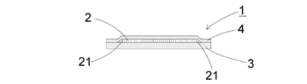
- FIG. 2 is a cross-sectional view taken along the line AA in FIG. It is explanatory drawing of the manufacturing apparatus of a glass film. It is the figure which provided the peeling start part in the support sheet and the protection sheet. It is a top view of 2nd Embodiment of the glass film laminated body which concerns on this invention.
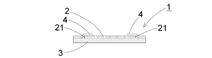
- FIG. 5 is a cross-sectional view taken along the line BB in FIG. It is a figure of the glass roll which concerns on this invention.
- the glass film laminate (1) according to the present invention has a glass film (2), a supporting glass (3), and a protective film (4) as shown in FIG.
- the glass film (2) is made of silicate glass, preferably silica glass or borosilicate glass, and most preferably non-alkali borosilicate glass.
- silicate glass preferably silica glass or borosilicate glass, and most preferably non-alkali borosilicate glass.
- the alkali-free borosilicate glass is a glass that does not substantially contain an alkali component, and specifically, a glass having an alkali component of 1000 ppm or less.
- the content of the alkali component in the present invention is preferably 500 ppm or less, more preferably 300 ppm or less of the alkali component.
- the thickness of the glass film (2) is preferably 300 ⁇ m or less, more preferably 5 ⁇ m to 200 ⁇ m, and most preferably 5 ⁇ m to 100 ⁇ m. As a result, the thickness of the glass film (2) can be made thinner and appropriate flexibility can be imparted, and manufacturing-related processing can also be performed on ultra-thin glass films that are prone to problems such as cracking and chipping. It can be done easily. When the thickness is less than 5 ⁇ m, the strength of the glass film (2) tends to be insufficient, and the glass film (2) is peeled off from the glass film laminate (1) and is easily damaged when incorporated into a device.
- the glass film (2) used in the present invention is preferably formed by the overflow down draw method as shown in FIG.
- the overflow down draw method is a molding method in which both sides of the glass plate do not come into contact with the molded member during molding, and both surfaces (translucent surface) of the obtained glass plate are hard to be scratched and have a high surface without being polished. This is because quality can be obtained.
- the glass ribbon (G) immediately after flowing down from the lower end portion (61) of the wedge-shaped molded body (6) is stretched downward while the shrinkage in the width direction is restricted by the cooling roller (7) to have a predetermined thickness. Until it gets thinner. Next, the glass ribbon (G) having reached the predetermined thickness is gradually cooled in a slow cooling furnace (annealer), the thermal distortion of the glass ribbon (G) is removed, the glass ribbon (G) is cut into a predetermined dimension, and glass A film (2) is formed.
- the support sheet (3) protrudes from the glass film (2) and is laminated as shown in FIG.
- the protruding amount is preferably from 0.1 cm to 50 cm, more preferably from 0.5 to 10 cm, from the edge (21) of the glass film (2). If the protruding amount is less than 0.1 cm, the protection of the edge (21) may tend to be insufficient, while if it exceeds 50 cm, handling may become difficult.
- a resin having flexibility in order to improve handling properties.
- polyethylene, polyvinyl chloride, polyethylene terephthalate, polyvinylidene chloride, polypropylene, polyvinyl alcohol, polyester, polycarbonate, Polystyrene, polyacrylonitrile, ethylene vinyl acetate copolymer, ethylene-vinyl alcohol copolymer, ethylene-methacrylic acid copolymer, nylon, cellophane, silicone resin and the like can be used.
- polyethylene terephthalate and polyethylene are preferably used.
- the support sheet (3) as a foamed resin, high flexibility is imparted to the support sheet (3). Moreover, it can prevent that the dust of an atmosphere adheres to a glass film (2) through a support sheet (3) by setting it as a closed cell type foamed resin.
- the color of the support sheet (3) to be laminated is not particularly limited and is colorless without coloring.
- the support sheet (3) may be colored white, black, blue, green, yellow, etc. in order to be able to determine whether the support sheet (3) has been peeled off from the glass film laminate (1). It is also possible.
- the translucency of the support sheet (3) is not particularly limited, and may be any of transparent, translucent, opaque, and the like.
- the thickness of the support sheet (3) is preferably 3 to 250 ⁇ m, more preferably 10 to 100 ⁇ m. Thereby, it becomes possible to support a glass film (2) reliably.
- the thickness of the support sheet (3) is less than 3 ⁇ m, the thickness of the support sheet (3) is too thin, and when the support sheet (3) exceeds 250 ⁇ m, the entire glass film laminate (1) is thick. If it is too large, the glass film laminate (1) may be difficult to handle.
- the conductive property is improved by adding a conductive substance to the support sheet (3) or forming a conductive film on the surface. It is preferable that it is provided. That is, when peeling the support sheet (3) from the glass film laminate (1), it is possible to prevent peeling electrification occurring between the glass film (2) and the support sheet (3). It is possible to prevent atmospheric dust or the like from adhering to the film (2) due to Coulomb force or the like.
- the support sheet (3) may be provided with tackiness, and the adhesive strength of the support sheet (3) in that case is preferably 0.002 to 2.00 N / 25 mm, more preferably 0.002. ⁇ 1.00 N / 25 mm, most preferably 0.005 to 0.9 N / 25 mm. This is because the support sheet (3) is weakly tacky, so that the support sheet (3) can be easily peeled from the glass film (2) after the protective sheet (4) is peeled off. This makes it possible to easily peel the support sheet (3) from the glass film laminate (1) after manufacturing-related processing, and to easily incorporate only the glass film (2) into various devices. .
- the adhesive strength of the support sheet (3) tends to be insufficient, and if it exceeds 2.00 N / 25 mm, the protective sheet (4) may be difficult to peel off.
- the adhesiveness is imparted to the entire surface of the support sheet (3), but it is not always necessary to impart it to the entire surface of the support sheet (3), and it is imparted only to the bonding surface with the glass film (2). You may let them.
- the protective sheet (4) is detachably laminated so as to cover the edge (21) of the glass film (2) on the other surface of the glass film (2) (the surface where the support sheet (3) is not in contact). Has been. Thereby, it becomes possible to protect the glass film edge (21) by sandwiching it between the support sheet (3) and the protective sheet (4). It is possible to prevent the stress from concentrating on the glass film edge (21), and the glass film (2) is not cracked or chipped with the fine scratches remaining on the end face of the glass film as the origin. It can prevent effectively and can improve the handleability of a glass film (2).
- a flexible resin for improving handling properties.
- polyethylene, polyvinyl chloride, polyethylene terephthalate, polyvinylidene chloride, polypropylene, polyvinyl alcohol, polyester, polycarbonate, Polystyrene, polyacrylonitrile, ethylene vinyl acetate copolymer, ethylene-vinyl alcohol copolymer, ethylene-methacrylic acid copolymer, nylon, cellophane, silicone resin and the like can be used.
- polyethylene terephthalate and polyethylene are preferably used.
- the protective sheet (4) as a foamed resin, high flexibility is imparted to the protective sheet (4). Moreover, it can prevent that the dust of an atmosphere adheres to a glass film (2) through a protective sheet (4) by using closed-cell type foamed resin. Since the protective sheet (4) is finally peeled and removed, the color is not particularly limited, it may be colorless without coloring, and whether the protective sheet (4) is peeled off from the glass film laminate (1). In order to be able to discriminate, it is also possible to color the protective sheet (4), such as white, black, blue, green, yellow. In this case, the translucency of the protective sheet (4) is not particularly limited, and may be any of transparent, translucent, opaque, and the like.
- the thickness of the protective sheet (4) is preferably 3 to 250 ⁇ m, and more preferably 10 to 100 ⁇ m. Thereby, it becomes possible to protect a glass film (2) and a support sheet (3) appropriately.
- the thickness of the protective sheet (4) is less than 3 ⁇ m, the thickness of the protective sheet (4) is too thin, and when the protective sheet (4) exceeds 250 ⁇ m, the entire glass film laminate (1) is thick. If it is too much, it may be difficult to appropriately protect the glass film laminate (1).
- the protective sheet (4) preferably covers the adhesive part of the support sheet (3). Thereby, it can prevent that dust etc. adhere to the adhesion part of a support sheet (3), or the support sheet (3) adheres in the case of handling of a glass film (2).
- the protective sheet (4) preferably covers the entire surface of the support sheet (3) protruding from the glass film (2).
- protective sheet (4) covers at least the portion to which the adhesiveness is given.
- the protective sheet (4) is preferably substantially the same size as the support sheet (3) as shown in FIG. Thereby, it becomes possible to completely cover the surfaces of the glass film (2) and the support sheet (3) with the protective sheet (4).
- the adhesive part of the support sheet (3) is exposed, dust or the like adheres to the adhesive part of the support sheet (3), or when the glass film (2) is handled, the support sheet (3) Adhesion to other members can be prevented, handling of the glass film (2) can be further facilitated, and the glass film (2) can be protected.
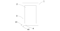
- FIG. 3 is a diagram in which a peeling start portion is provided on the support sheet and the protective sheet.
- the support sheet (3) and the protective sheet (4) are provided with a peeling start portion (31) (41) in the vicinity thereof so as to protrude about 1 cm at the maximum from the glass film laminate (1).
- a peeling start portion (31) (41) in the vicinity thereof so as to protrude about 1 cm at the maximum from the glass film laminate (1).
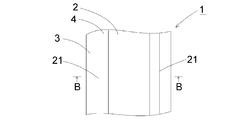
- FIG. 4 is a diagram of a second embodiment of the glass film laminate according to the present invention, wherein (a) is a plan view and (b) is a cross-sectional view taken along the line BB.
- the protective sheet (4) covers only the vicinity of the adhesive surface of the support sheet (3) and the glass film edge (21), The effective surface of the glass film (2) is not covered with the protective sheet (4). Thereby, the edge (21) of the glass film is protected by the protective sheet (4), and the glass film (2) is effectively prevented from being cracked or chipped, and the glass film (2) is easy to handle. Manufacturing related processing such as film formation and patterning can be performed on the effective surface of the glass film (2).
- FIG. 5 is a diagram of a glass roll according to the present invention.
- the glass roll (5) which concerns on this invention is formed by winding up the glass film laminated body (1) mentioned above. Thereby, even if it produces the glass roll (5) in which stress tends to concentrate especially on a glass film edge (21), it can wind up, preventing generation
- the support sheet (3) has an adhesive surface covered by the protective sheet (4), even if the glass film laminate (1) is wound to form a glass roll (5), it is double-tripled by winding.
- the support sheets (3) thus formed can be prevented from sticking to each other and sticking, and the cause of bending during winding can be eliminated.
- the present invention can be suitably used for glass substrates used in flat panel displays such as liquid crystal displays and organic EL displays, devices such as solar cells, and cover glasses for organic EL lighting.
Landscapes
- Chemical & Material Sciences (AREA)
- Engineering & Computer Science (AREA)
- Materials Engineering (AREA)
- Organic Chemistry (AREA)
- Laminated Bodies (AREA)
- Surface Treatment Of Glass (AREA)
Abstract
Description
2 ガラスフィルム
21 縁部
3 支持シート
4 保護シート
5 ガラスロール
Claims (10)
- ガラスフィルムと、
該ガラスフィルムの一方の面に前記ガラスフィルムから食み出して積層された支持シートと、
前記ガラスフィルムの他方の面に、前記ガラスフィルムの縁部を覆うように剥離可能に積層された保護シートと、
を有するガラスフィルム積層体。 - 前記ガラスフィルムの厚みは、300μm以下であることを特徴とする請求項1に記載のガラスフィルム積層体。
- 前記支持シートの粘着力は、0.002~2.00N/25mmであることを特徴とする請求項1又は2に記載のガラスフィルム積層体。
- 前記支持シートの厚みは、3~250μmであることを特徴とする請求項1~3のいずれかに記載のガラスフィルム積層体。
- 前記保護シートの厚みは、3~250μmであることを特徴とする請求項1~4のいずれかに記載のガラスフィルム積層体。
- 前記保護シートは、前記支持シートの粘着部分を覆っていることを特徴とする請求項1~5のいずれかに記載のガラスフィルム積層体。
- 前記保護シートは、前記支持シートと実質的に同一の大きさであることを特徴とする請求項1~6のいずれかに記載のガラスフィルム積層体。
- 請求項6又は7に記載のガラスフィルム積層体を巻き取ったガラスロール。
- ガラスフィルムの一方の面にガラスフィルムから食み出して粘着性の支持シートを積層し、前記ガラスフィルムの他方の面に前記ガラスフィルムの縁部を覆うように剥離可能に保護シートを積層することを特徴とするガラスフィルムの端面保護方法。
- ガラスフィルムの一方の面に前記ガラスフィルムから食み出して粘着性の支持シートを積層し、前記ガラスフィルムの他方の面に前記ガラスフィルムの縁部と前記支持シートの粘着部分とを覆うように剥離可能に保護シートを積層することによって作製されたガラスフィルム積層体を巻き取ることを特徴とするガラスロールの製造方法。
Priority Applications (2)
| Application Number | Priority Date | Filing Date | Title |
|---|---|---|---|
| DE112010001334.9T DE112010001334B4 (de) | 2009-03-26 | 2010-02-23 | Glasrolle und Verfahren zur Herstellung einer Glasrolle |
| CN201080003909.2A CN102271909B (zh) | 2009-03-26 | 2010-02-23 | 玻璃膜层叠体、该层叠体的玻璃辊、玻璃膜的端面保护方法及玻璃辊的制造方法 |
Applications Claiming Priority (2)
| Application Number | Priority Date | Filing Date | Title |
|---|---|---|---|
| JP2009-075986 | 2009-03-26 | ||
| JP2009075986A JP5510880B2 (ja) | 2009-03-26 | 2009-03-26 | ガラスフィルム積層体、該積層体のガラスロール、及びガラスロールの製造方法 |
Publications (1)
| Publication Number | Publication Date |
|---|---|
| WO2010110002A1 true WO2010110002A1 (ja) | 2010-09-30 |
Family
ID=42780697
Family Applications (1)
| Application Number | Title | Priority Date | Filing Date |
|---|---|---|---|
| PCT/JP2010/052745 Ceased WO2010110002A1 (ja) | 2009-03-26 | 2010-02-23 | ガラスフィルム積層体、該積層体のガラスロール、ガラスフィルムの端面保護方法、及びガラスロールの製造方法 |
Country Status (7)
| Country | Link |
|---|---|
| US (1) | US8304058B2 (ja) |
| JP (1) | JP5510880B2 (ja) |
| KR (1) | KR101618647B1 (ja) |
| CN (1) | CN102271909B (ja) |
| DE (1) | DE112010001334B4 (ja) |
| TW (1) | TWI465335B (ja) |
| WO (1) | WO2010110002A1 (ja) |
Cited By (3)
| Publication number | Priority date | Publication date | Assignee | Title |
|---|---|---|---|---|
| WO2011071067A1 (ja) * | 2009-12-11 | 2011-06-16 | 日本電気硝子株式会社 | ガラスフィルム積層体、該積層体のガラスロール、及びガラスロールの製造方法 |
| CN104520218A (zh) * | 2011-11-30 | 2015-04-15 | 康宁股份有限公司 | 用于传送柔性玻璃基板的方法和设备 |
| JP2017178778A (ja) * | 2009-07-29 | 2017-10-05 | コーニング インコーポレイテッド | エッジウエブ部を有するガラス基板 |
Families Citing this family (24)
| Publication number | Priority date | Publication date | Assignee | Title |
|---|---|---|---|---|
| TWI542527B (zh) * | 2010-11-30 | 2016-07-21 | 康寧公司 | 藉由張緊交插材料捲繞玻璃帶 |
| KR101069642B1 (ko) * | 2011-02-16 | 2011-10-04 | 이학철 | 휴대용 단말기의 디스플레이 보호필름 |
| US20120255672A1 (en) * | 2011-04-11 | 2012-10-11 | Marshall Dale C | Methods and apparatuses for applying a handling tab to continuous glass ribbons |
| JP5704450B2 (ja) * | 2011-04-13 | 2015-04-22 | 大日本印刷株式会社 | カラーフィルターの製造方法 |
| JP5704453B2 (ja) * | 2011-04-22 | 2015-04-22 | 大日本印刷株式会社 | ガラスフィルム積層体、ガラスフィルム積層体ロール、カラーフィルタ用の画素付ガラスフィルム積層体およびガラスフィルム積層体の製造方法 |
| JP5849492B2 (ja) * | 2011-07-25 | 2016-01-27 | 大日本印刷株式会社 | ガラスフィルム積層体の製造方法 |
| JP5737625B2 (ja) * | 2011-08-04 | 2015-06-17 | 大日本印刷株式会社 | ガラスフィルム積層体、ガラスフィルム積層体ロール、カラーフィルタ用画素付ガラスフィルム積層体およびガラスフィルム積層体の製造方法 |
| JP5987312B2 (ja) * | 2011-12-16 | 2016-09-07 | 日本電気硝子株式会社 | 成膜装置及び膜付ガラスフィルムの製造方法 |
| US20130196163A1 (en) * | 2012-01-31 | 2013-08-01 | 3M Innovative Properties Company | Composite glass laminate and web processing apparatus |
| EP3470223A1 (en) * | 2012-07-02 | 2019-04-17 | Corning Incorporated | Methods of processing a glass substrate |
| US9216924B2 (en) * | 2012-11-09 | 2015-12-22 | Corning Incorporated | Methods of processing a glass ribbon |
| JP6086773B2 (ja) | 2013-03-21 | 2017-03-01 | 日東電工株式会社 | 薄ガラス長尺体 |
| JP6119511B2 (ja) * | 2013-08-27 | 2017-04-26 | 旭硝子株式会社 | ガラス梱包体 |
| US10688768B2 (en) * | 2014-08-15 | 2020-06-23 | 3M Innovative Properties Company | Glass and polymer film assemblies and methods of making |
| DE102014221245A1 (de) | 2014-10-20 | 2016-04-21 | Tesa Se | Dünnglasfolienverbundbahn mit Versteifungsstreifen |
| CN107001136B (zh) * | 2015-03-09 | 2020-12-01 | 日本电气硝子株式会社 | 层叠体及其制造方法 |
| DE102015106050A1 (de) | 2015-04-21 | 2016-10-27 | Schott Ag | Glasrolle, Erzeugnis mit einer Glasrolle, Vorrichtung und Verfahren zu deren Herstellung |
| CN108349790B (zh) | 2015-10-20 | 2020-09-15 | Agc株式会社 | 玻璃-树脂复合体及其制造方法 |
| CN109311620B (zh) * | 2016-10-17 | 2021-03-19 | 日本电气硝子株式会社 | 玻璃辊 |
| JP6839419B2 (ja) * | 2017-07-31 | 2021-03-10 | 日本電気硝子株式会社 | ガラスフィルムの製造方法 |
| CN111670393A (zh) * | 2018-01-31 | 2020-09-15 | 日东电工株式会社 | 光学层叠体辊 |
| JP7357500B2 (ja) * | 2019-09-26 | 2023-10-06 | 日東電工株式会社 | 複層構造体 |
| JP7192753B2 (ja) * | 2019-12-09 | 2022-12-20 | 日本電気硝子株式会社 | ガラスロール |
| CN112937012A (zh) * | 2021-01-18 | 2021-06-11 | 江苏新澄瑞材料科技有限公司 | 一种柔性盖板及其加工方法 |
Citations (6)
| Publication number | Priority date | Publication date | Assignee | Title |
|---|---|---|---|---|
| JPH1095636A (ja) * | 1996-09-17 | 1998-04-14 | Nippon Sheet Glass Co Ltd | 耐衝撃ガラス |
| JP2001113631A (ja) * | 1999-10-20 | 2001-04-24 | Mitsubishi Plastics Ind Ltd | プラスチックフィルム・ガラスフィルム積層体 |
| JP2003039597A (ja) * | 2001-08-02 | 2003-02-13 | Mitsubishi Plastics Ind Ltd | 積層体 |
| JP2007010834A (ja) * | 2005-06-29 | 2007-01-18 | Sumitomo Chemical Co Ltd | ディスプレイ用基板及びそれを用いたディスプレイ素子 |
| JP2007331996A (ja) * | 2006-06-16 | 2007-12-27 | Asahi Glass Co Ltd | 機能性ガラス体 |
| WO2009093505A1 (ja) * | 2008-01-25 | 2009-07-30 | Asahi Glass Company, Limited | ガラス樹脂複合体の製造方法 |
Family Cites Families (3)
| Publication number | Priority date | Publication date | Assignee | Title |
|---|---|---|---|---|
| JPH021147A (ja) * | 1988-02-15 | 1990-01-05 | Tomoegawa Paper Co Ltd | 半導体デバイス用ガラスキャップの包装体 |
| JP4326635B2 (ja) | 1999-09-29 | 2009-09-09 | 三菱樹脂株式会社 | ガラスフィルムの取扱い方法及びガラス積層体 |
| JP5177790B2 (ja) | 2006-10-24 | 2013-04-10 | 日本電気硝子株式会社 | ガラスリボンの製造装置及びその製造方法 |
-
2009
- 2009-03-26 JP JP2009075986A patent/JP5510880B2/ja active Active
-
2010
- 2010-02-23 CN CN201080003909.2A patent/CN102271909B/zh active Active
- 2010-02-23 KR KR1020117010517A patent/KR101618647B1/ko active Active
- 2010-02-23 WO PCT/JP2010/052745 patent/WO2010110002A1/ja not_active Ceased
- 2010-02-23 US US12/710,631 patent/US8304058B2/en active Active
- 2010-02-23 TW TW099105254A patent/TWI465335B/zh active
- 2010-02-23 DE DE112010001334.9T patent/DE112010001334B4/de active Active
Patent Citations (6)
| Publication number | Priority date | Publication date | Assignee | Title |
|---|---|---|---|---|
| JPH1095636A (ja) * | 1996-09-17 | 1998-04-14 | Nippon Sheet Glass Co Ltd | 耐衝撃ガラス |
| JP2001113631A (ja) * | 1999-10-20 | 2001-04-24 | Mitsubishi Plastics Ind Ltd | プラスチックフィルム・ガラスフィルム積層体 |
| JP2003039597A (ja) * | 2001-08-02 | 2003-02-13 | Mitsubishi Plastics Ind Ltd | 積層体 |
| JP2007010834A (ja) * | 2005-06-29 | 2007-01-18 | Sumitomo Chemical Co Ltd | ディスプレイ用基板及びそれを用いたディスプレイ素子 |
| JP2007331996A (ja) * | 2006-06-16 | 2007-12-27 | Asahi Glass Co Ltd | 機能性ガラス体 |
| WO2009093505A1 (ja) * | 2008-01-25 | 2009-07-30 | Asahi Glass Company, Limited | ガラス樹脂複合体の製造方法 |
Cited By (6)
| Publication number | Priority date | Publication date | Assignee | Title |
|---|---|---|---|---|
| JP2017178778A (ja) * | 2009-07-29 | 2017-10-05 | コーニング インコーポレイテッド | エッジウエブ部を有するガラス基板 |
| US10183826B2 (en) | 2009-07-29 | 2019-01-22 | Corning Incorporated | Glass substrate comprising an edge web portion |
| WO2011071067A1 (ja) * | 2009-12-11 | 2011-06-16 | 日本電気硝子株式会社 | ガラスフィルム積層体、該積層体のガラスロール、及びガラスロールの製造方法 |
| CN104520218A (zh) * | 2011-11-30 | 2015-04-15 | 康宁股份有限公司 | 用于传送柔性玻璃基板的方法和设备 |
| CN104520218B (zh) * | 2011-11-30 | 2016-10-12 | 康宁股份有限公司 | 用于传送柔性玻璃基板的方法和设备 |
| TWI610870B (zh) * | 2011-11-30 | 2018-01-11 | 康寧公司 | 用於運輸彈性玻璃基板的方法及設備 |
Also Published As
| Publication number | Publication date |
|---|---|
| TWI465335B (zh) | 2014-12-21 |
| DE112010001334B4 (de) | 2024-03-07 |
| DE112010001334T5 (de) | 2012-07-05 |
| KR20110132547A (ko) | 2011-12-08 |
| TW201038398A (en) | 2010-11-01 |
| US20100260964A1 (en) | 2010-10-14 |
| KR101618647B1 (ko) | 2016-05-09 |
| US8304058B2 (en) | 2012-11-06 |
| CN102271909B (zh) | 2014-06-11 |
| JP2010228166A (ja) | 2010-10-14 |
| CN102271909A (zh) | 2011-12-07 |
| JP5510880B2 (ja) | 2014-06-04 |
Similar Documents
| Publication | Publication Date | Title |
|---|---|---|
| JP5510880B2 (ja) | ガラスフィルム積層体、該積層体のガラスロール、及びガラスロールの製造方法 | |
| WO2011071067A1 (ja) | ガラスフィルム積層体、該積層体のガラスロール、及びガラスロールの製造方法 | |
| JP5594522B2 (ja) | 電子デバイス製造用ガラスフィルム積層体 | |
| US9333724B2 (en) | Glass film laminate | |
| JP5874159B2 (ja) | ガラス−樹脂積層体、およびそれを巻き取ったガラスロール、並びにガラスロールの製造方法 | |
| JP5510901B2 (ja) | ガラスフィルムの製造方法及びガラスフィルムの処理方法並びにガラスフィルム積層体 | |
| JP5692513B2 (ja) | ガラスフィルム積層体 | |
| JP2010194874A (ja) | ガラスフィルム積層体、及び該積層体のガラスロール | |
| JP5585937B2 (ja) | ガラスフィルム積層体 | |
| CN105764867A (zh) | 玻璃膜层叠体的制造方法、玻璃膜层叠体、电子设备的制造方法 | |
| JP2010215436A (ja) | ガラスフィルム積層体 |
Legal Events
| Date | Code | Title | Description |
|---|---|---|---|
| WWE | Wipo information: entry into national phase |
Ref document number: 201080003909.2 Country of ref document: CN |
|
| 121 | Ep: the epo has been informed by wipo that ep was designated in this application |
Ref document number: 10755803 Country of ref document: EP Kind code of ref document: A1 |
|
| ENP | Entry into the national phase |
Ref document number: 20117010517 Country of ref document: KR Kind code of ref document: A |
|
| WWE | Wipo information: entry into national phase |
Ref document number: 112010001334 Country of ref document: DE Ref document number: 1120100013349 Country of ref document: DE |
|
| 122 | Ep: pct application non-entry in european phase |
Ref document number: 10755803 Country of ref document: EP Kind code of ref document: A1 |