WO2010084683A1 - 治療処置装置および治療用処置具 - Google Patents
治療処置装置および治療用処置具 Download PDFInfo
- Publication number
- WO2010084683A1 WO2010084683A1 PCT/JP2009/071275 JP2009071275W WO2010084683A1 WO 2010084683 A1 WO2010084683 A1 WO 2010084683A1 JP 2009071275 W JP2009071275 W JP 2009071275W WO 2010084683 A1 WO2010084683 A1 WO 2010084683A1
- Authority
- WO
- WIPO (PCT)
- Prior art keywords
- energy
- treatment
- joined
- holding
- holding members
- Prior art date
- Legal status (The legal status is an assumption and is not a legal conclusion. Google has not performed a legal analysis and makes no representation as to the accuracy of the status listed.)
- Ceased
Links
Images


Classifications
-
- A—HUMAN NECESSITIES
- A61—MEDICAL OR VETERINARY SCIENCE; HYGIENE
- A61B—DIAGNOSIS; SURGERY; IDENTIFICATION
- A61B18/00—Surgical instruments, devices or methods for transferring non-mechanical forms of energy to or from the body
- A61B18/04—Surgical instruments, devices or methods for transferring non-mechanical forms of energy to or from the body by heating
- A61B18/12—Surgical instruments, devices or methods for transferring non-mechanical forms of energy to or from the body by heating by passing a current through the tissue to be heated, e.g. high-frequency current
- A61B18/14—Probes or electrodes therefor
- A61B18/1442—Probes having pivoting end effectors, e.g. forceps
- A61B18/1445—Probes having pivoting end effectors, e.g. forceps at the distal end of a shaft, e.g. forceps or scissors at the end of a rigid rod
-
- A—HUMAN NECESSITIES
- A61—MEDICAL OR VETERINARY SCIENCE; HYGIENE
- A61B—DIAGNOSIS; SURGERY; IDENTIFICATION
- A61B18/00—Surgical instruments, devices or methods for transferring non-mechanical forms of energy to or from the body
- A61B18/04—Surgical instruments, devices or methods for transferring non-mechanical forms of energy to or from the body by heating
- A61B18/08—Surgical instruments, devices or methods for transferring non-mechanical forms of energy to or from the body by heating by means of electrically-heated probes
- A61B18/082—Probes or electrodes therefor
- A61B18/085—Forceps, scissors
-
- A—HUMAN NECESSITIES
- A61—MEDICAL OR VETERINARY SCIENCE; HYGIENE
- A61B—DIAGNOSIS; SURGERY; IDENTIFICATION
- A61B18/00—Surgical instruments, devices or methods for transferring non-mechanical forms of energy to or from the body
- A61B18/04—Surgical instruments, devices or methods for transferring non-mechanical forms of energy to or from the body by heating
- A61B18/12—Surgical instruments, devices or methods for transferring non-mechanical forms of energy to or from the body by heating by passing a current through the tissue to be heated, e.g. high-frequency current
- A61B18/1206—Generators therefor
-
- A—HUMAN NECESSITIES
- A61—MEDICAL OR VETERINARY SCIENCE; HYGIENE
- A61B—DIAGNOSIS; SURGERY; IDENTIFICATION
- A61B18/00—Surgical instruments, devices or methods for transferring non-mechanical forms of energy to or from the body
- A61B18/04—Surgical instruments, devices or methods for transferring non-mechanical forms of energy to or from the body by heating
- A61B18/12—Surgical instruments, devices or methods for transferring non-mechanical forms of energy to or from the body by heating by passing a current through the tissue to be heated, e.g. high-frequency current
- A61B18/14—Probes or electrodes therefor
- A61B18/1482—Probes or electrodes therefor having a long rigid shaft for accessing the inner body transcutaneously in minimal invasive surgery, e.g. laparoscopy
-
- A—HUMAN NECESSITIES
- A61—MEDICAL OR VETERINARY SCIENCE; HYGIENE
- A61B—DIAGNOSIS; SURGERY; IDENTIFICATION
- A61B17/00—Surgical instruments, devices or methods
- A61B17/32—Surgical cutting instruments
- A61B17/320068—Surgical cutting instruments using mechanical vibrations, e.g. ultrasonic
- A61B17/320092—Surgical cutting instruments using mechanical vibrations, e.g. ultrasonic with additional movable means for clamping or cutting tissue, e.g. with a pivoting jaw
- A61B2017/320095—Surgical cutting instruments using mechanical vibrations, e.g. ultrasonic with additional movable means for clamping or cutting tissue, e.g. with a pivoting jaw with sealing or cauterizing means
-
- A—HUMAN NECESSITIES
- A61—MEDICAL OR VETERINARY SCIENCE; HYGIENE
- A61B—DIAGNOSIS; SURGERY; IDENTIFICATION
- A61B18/00—Surgical instruments, devices or methods for transferring non-mechanical forms of energy to or from the body
- A61B2018/00636—Sensing and controlling the application of energy
- A61B2018/00642—Sensing and controlling the application of energy with feedback, i.e. closed loop control
-
- A—HUMAN NECESSITIES
- A61—MEDICAL OR VETERINARY SCIENCE; HYGIENE
- A61B—DIAGNOSIS; SURGERY; IDENTIFICATION
- A61B18/00—Surgical instruments, devices or methods for transferring non-mechanical forms of energy to or from the body
- A61B2018/00636—Sensing and controlling the application of energy
- A61B2018/00696—Controlled or regulated parameters
- A61B2018/00702—Power or energy
-
- A—HUMAN NECESSITIES
- A61—MEDICAL OR VETERINARY SCIENCE; HYGIENE
- A61B—DIAGNOSIS; SURGERY; IDENTIFICATION
- A61B18/00—Surgical instruments, devices or methods for transferring non-mechanical forms of energy to or from the body
- A61B2018/00636—Sensing and controlling the application of energy
- A61B2018/00773—Sensed parameters
- A61B2018/00827—Current
-
- A—HUMAN NECESSITIES
- A61—MEDICAL OR VETERINARY SCIENCE; HYGIENE
- A61B—DIAGNOSIS; SURGERY; IDENTIFICATION
- A61B18/00—Surgical instruments, devices or methods for transferring non-mechanical forms of energy to or from the body
- A61B2018/00636—Sensing and controlling the application of energy
- A61B2018/00773—Sensed parameters
- A61B2018/00869—Phase
-
- A—HUMAN NECESSITIES
- A61—MEDICAL OR VETERINARY SCIENCE; HYGIENE
- A61B—DIAGNOSIS; SURGERY; IDENTIFICATION
- A61B18/00—Surgical instruments, devices or methods for transferring non-mechanical forms of energy to or from the body
- A61B2018/00636—Sensing and controlling the application of energy
- A61B2018/00773—Sensed parameters
- A61B2018/00875—Resistance or impedance
-
- A—HUMAN NECESSITIES
- A61—MEDICAL OR VETERINARY SCIENCE; HYGIENE
- A61B—DIAGNOSIS; SURGERY; IDENTIFICATION
- A61B18/00—Surgical instruments, devices or methods for transferring non-mechanical forms of energy to or from the body
- A61B2018/00636—Sensing and controlling the application of energy
- A61B2018/00773—Sensed parameters
- A61B2018/00892—Voltage
-
- A—HUMAN NECESSITIES
- A61—MEDICAL OR VETERINARY SCIENCE; HYGIENE
- A61B—DIAGNOSIS; SURGERY; IDENTIFICATION
- A61B18/00—Surgical instruments, devices or methods for transferring non-mechanical forms of energy to or from the body
- A61B18/04—Surgical instruments, devices or methods for transferring non-mechanical forms of energy to or from the body by heating
- A61B18/12—Surgical instruments, devices or methods for transferring non-mechanical forms of energy to or from the body by heating by passing a current through the tissue to be heated, e.g. high-frequency current
- A61B18/14—Probes or electrodes therefor
- A61B2018/1472—Probes or electrodes therefor for use with liquid electrolyte, e.g. virtual electrodes
-
- A—HUMAN NECESSITIES
- A61—MEDICAL OR VETERINARY SCIENCE; HYGIENE
- A61B—DIAGNOSIS; SURGERY; IDENTIFICATION
- A61B18/00—Surgical instruments, devices or methods for transferring non-mechanical forms of energy to or from the body
- A61B18/04—Surgical instruments, devices or methods for transferring non-mechanical forms of energy to or from the body by heating
- A61B18/12—Surgical instruments, devices or methods for transferring non-mechanical forms of energy to or from the body by heating by passing a current through the tissue to be heated, e.g. high-frequency current
- A61B18/14—Probes or electrodes therefor
- A61B2018/1475—Electrodes retractable in or deployable from a housing
-
- A—HUMAN NECESSITIES
- A61—MEDICAL OR VETERINARY SCIENCE; HYGIENE
- A61B—DIAGNOSIS; SURGERY; IDENTIFICATION
- A61B2218/00—Details of surgical instruments, devices or methods for transferring non-mechanical forms of energy to or from the body
- A61B2218/001—Details of surgical instruments, devices or methods for transferring non-mechanical forms of energy to or from the body having means for irrigation and/or aspiration of substances to and/or from the surgical site
- A61B2218/002—Irrigation
-
- A—HUMAN NECESSITIES
- A61—MEDICAL OR VETERINARY SCIENCE; HYGIENE
- A61N—ELECTROTHERAPY; MAGNETOTHERAPY; RADIATION THERAPY; ULTRASOUND THERAPY
- A61N7/00—Ultrasound therapy
- A61N7/02—Localised ultrasound hyperthermia
Definitions
- the present invention relates to a therapeutic treatment apparatus and a therapeutic treatment tool capable of joining a plurality of living tissues using energy.
- both laparoscopic surgery and laparoscopic surgery may seal luminal tissues such as blood vessels and join other biological tissues.
- luminal tissues such as blood vessels and join other biological tissues.
- a thread or clip is used to seal the blood vessel to be separated. Threads and staples are used to seal and anastomoses the resected end of the digestive tract.
- technology using energy has been used.
- other devices used for thicker tissues are also progressing.
- the device for sealing and joining biological tissues with energy fuses biological tissues with grasping forceps having electrodes. In such a procedure, it is necessary to administer energy to a portion (joint portion) where the living tissues to be joined come into contact with each other and sufficiently denature and dehydrate the living tissue in the joined portion.
- USP 6,500,176 B1 discloses a bipolar device.
- This bipolar device discloses a technique in which an electrode is inserted into the center of living tissues to be joined and electric energy is passed from the electrodes between the living tissues to the grasping forceps. For this reason, this bipolar device can weld and seal a living tissue having a thickness or a living tissue having various compositions.
- Japanese Patent Application Laid-Open No. 2007-229270 discloses a technique in which energy is directly applied to a joint surface of living tissue to be joined.
- Japanese Patent Laid-Open No. 2007-229270 is a technique for heating and bonding a living tissue by placing an ultrasonic probe on the bonding surface of the living tissue and ultrasonically vibrating the ultrasonic probe on the bonding surface.
- an ultrasonic probe is positioned on the joint surface of the tissue grasped by the holding portion, and vibration and temperature are applied.
- the output is switched according to the state of the tissue, etc. Since there is no mechanism, the tissue cannot be sufficiently dehydrated and denatured.
- the present invention relates to a therapeutic treatment apparatus and a therapeutic device that can switch the combination of electrodes while monitoring the tissue state, efficiently concentrate energy on the tissue joint surface, and more easily denature and dehydrate the tissue joint surface. It aims at providing a treatment tool.
- a therapeutic treatment apparatus for joining living body tissues to be joined in the body includes an energy source for applying energy to the living tissues to be joined, and joining when the energy is applied from the energy source.
- the first treatment section is provided on at least one pair of holding members each having a holding surface for holding living tissues to be joined, and the holding surface of the holding member, and when energy is applied from the energy source And an energy release unit for joining biological tissues to be joined.
- the detection unit detects at least one of biological information of the biological tissue held by the pair of holding members and biological information of the biological tissue between the pair of holding members and the second treatment unit. .
- the control unit controls outputs of the energy emitting unit and the second treatment unit based on biological information of the biological tissue obtained by the detection unit.
- a therapeutic treatment tool for joining living body tissues to be joined in the body includes a first treatment unit for joining biological tissues to be joined when energy is applied from an energy source; A second treatment unit that is sandwiched between biological tissues to be joined and denatures a surface that is in contact with the biological tissues to be joined, and an operation unit are provided.
- the first treatment section is provided on at least one pair of holding members each having a holding surface for holding living tissues to be joined, and the holding surface of the holding member, and when energy is applied from the energy source And an energy release unit for joining biological tissues to be joined.
- the operation unit has a function of operating so that at least one of the holding members moves relative to the other.
- the energy release unit and the second treatment unit include biological information of the biological tissue held by the pair of holding members, and a biological tissue of the biological tissue between the pair of holding members and the second treatment unit. At least one of the information can be detected, and output from the energy source to the energy emitting unit and the second treatment unit based on the biological information of the biological tissue obtained by the energy emitting unit and the second treatment unit The energy to be controlled is controlled.
- a therapeutic treatment apparatus capable of efficiently concentrating energy on the tissue joint surface by switching the combination of electrodes while monitoring the tissue state, and denatured / dehydrated the tissue joint surface more easily.
- a therapeutic treatment tool can be provided.
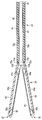
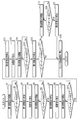
- FIG. 1A is a schematic perspective view showing a treatment apparatus according to the first embodiment.
- FIG. 1B is a partial cross-sectional view of the handle and shaft of the energy treatment device of the treatment apparatus according to the first embodiment.
- FIG. 2 is a schematic diagram showing the therapeutic treatment apparatus according to the first embodiment.
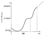
- FIG. 3 is a schematic diagram showing the relationship between time and impedance of a living tissue when the living tissue is treated by continuously energizing the living tissue with high-frequency energy using the treatment apparatus.
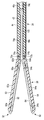
- FIG. 4A shows a rod-shaped electrode between the shaft of the energy treatment device of the treatment apparatus according to the first embodiment and the first and second holding members, and between the first and second holding members. It is a schematic longitudinal cross-sectional view which shows the treatment part of the state which has arrange
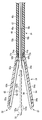
- FIG. 4B shows the rod-shaped electrode between the first holding member and the first holding member, and the shaft of the energy treatment device of the treatment apparatus according to the first embodiment and the first and second holding members are opened. It is a schematic longitudinal cross-sectional view which shows the treatment part of the state which has arrange
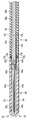
- FIG. 4C shows a shaft of the energy treatment device of the treatment apparatus according to the first embodiment, the first and second holding members, and a rod-shaped electrode from between the first and second holding members. It is a schematic longitudinal cross-sectional view which shows the treatment part of the state which pulled in the inside of a shaft.
- FIG. 4D closes the first and second holding members of the treatment unit of the energy treatment device of the treatment apparatus according to the first embodiment, and the rod-shaped electrode is interposed between the first and second holding members.
- FIG. 4B is a schematic cross-sectional view taken along line 4D-4D in FIG.
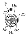
- FIG. 5A is a schematic diagram illustrating a holding surface of the main body of the first holding member of the treatment unit of the energy treatment device of the treatment apparatus according to the first embodiment.
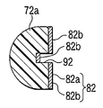
- FIG. 5B is a schematic cross-sectional view taken along line 5B-5B in FIG. 5A, showing the main body of the first holding member of the treatment portion of the energy treatment device of the treatment apparatus according to the first embodiment. is there.
- FIG. 6 is a flowchart when the living tissues are joined using the treatment apparatus according to the first embodiment.
- FIG. 7A is a schematic diagram illustrating a holding surface of a main body of a first holding member of a treatment unit of an energy treatment device of a treatment apparatus according to a modification of the first embodiment.
- FIG. 7B is a schematic cross-section taken along line 7B-7B in FIG. 7A, showing the main body of the first holding member of the treatment portion of the energy treatment device of the treatment apparatus according to the modification of the first embodiment.
- FIG. FIG. 8A closes the shaft of the energy treatment device of the treatment apparatus according to the modification of the first embodiment, the first and second holding members, and between the first and second holding members.
- FIG. 8B shows the shaft of the energy treatment device of the treatment apparatus according to the modification of the first embodiment, the first and second holding members opened, and between the first and second holding members.
- FIG. 8C opens the shaft of the energy treatment device and the first and second holding members of the treatment apparatus according to the modification of the first embodiment, and opens between the first and second holding members.
- FIG. 8C opens the shaft of the energy treatment device and the first and second holding members of the treatment apparatus according to the modification of the first embodiment, and opens between the first and second holding members.
- FIG. 9 is a schematic cross-sectional view taken along line 8D-8D in FIG. 8A, showing a state in which rod-shaped electrodes are arranged.
- FIG. 9 is a schematic perspective view showing a treatment apparatus according to a modification of the first embodiment.
- FIG. 10 is a schematic perspective view showing a treatment apparatus according to a modification of the first embodiment.
- FIG. 11 is a schematic perspective view showing the treatment apparatus according to the second embodiment.
- FIG. 12A shows a rod-shaped electrode between the shaft of the energy treatment device of the treatment apparatus according to the second embodiment and the first and second holding members, and between the first and second holding members. It is a schematic longitudinal cross-sectional view which shows the treatment part of the state which has arrange
- FIG. 12B shows the rod-shaped electrode between the first holding member and the shaft of the energy treatment device of the treatment apparatus according to the second embodiment, and the first and second holding members opened. It is a schematic longitudinal cross-sectional view which shows the treatment part of the state which has arrange
- FIG. 12C shows the rod-shaped electrode between the first holding member and the shaft of the energy treatment device of the treatment apparatus according to the second embodiment, and the first and second holding members are opened.
- FIG. 12D shows the rod-shaped electrode between the first and second holding members, and the first and second holding members of the treatment unit of the energy treatment device of the treatment apparatus according to the second embodiment are closed.
- FIG. 12B is a schematic cross-sectional view taken along line 12D-12D in FIG.
- FIG. 13 is a flowchart when the living tissue is joined using the treatment apparatus according to the second embodiment.
- FIG. 14A closes the shaft of the energy treatment device of the treatment apparatus according to the modification of the second embodiment and the first and second holding members, and between the first and second holding members.
- FIG. 14B shows the shaft of the energy treatment device of the treatment apparatus according to the modification of the second embodiment, the first and second holding members opened, and the gap between the first and second holding members. It is a schematic longitudinal cross-sectional view which shows the treatment part of the state which has arrange
- FIG. 14C shows the shaft of the energy treatment device and the first and second holding members of the treatment apparatus according to the modification of the second embodiment, and the gap between the first and second holding members. It is a schematic longitudinal cross-sectional view which shows the treatment part of the state which cut
- FIG. 14D closes the first and second holding members of the treatment unit of the energy treatment device of the treatment apparatus according to the modification of the second embodiment, and between the first and second holding members.
- FIG. 14B is a schematic cross-sectional view taken along line 14D-14D in FIG. 14A, showing a state in which rod-shaped electrodes are arranged.
- FIG. 15 is a schematic perspective view showing the treatment apparatus according to the third embodiment.
- FIG. 16 is a schematic diagram showing a treatment apparatus according to the third embodiment.
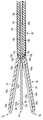
- FIG. 17A shows a tubular electrode between the shaft of the energy treatment device of the treatment apparatus according to the third embodiment and the first and second holding members, and between the first and second holding members. It is a schematic longitudinal cross-sectional view which shows the treatment part of the state which has arrange
- FIG. 17B shows the shaft of the energy treatment device of the treatment apparatus according to the third embodiment, the first and second holding members, and a tubular electrode between the first and second holding members.
- FIG. 17C shows the shaft of the energy treatment device of the treatment apparatus according to the third embodiment, the first and second holding members, and the tubular electrode between the first and second holding members.
- FIG. 17D closes the first and second holding members of the treatment unit of the energy treatment device of the treatment apparatus according to the third embodiment, and the tubular electrode is between the first and second holding members.
- FIG. 18B is a schematic cross-sectional view taken along line 17D-17D in FIG.
- FIG. 18 is a flowchart when a living tissue is joined using the treatment apparatus according to the third embodiment.
- FIG. 19A is a schematic diagram illustrating a holding surface of a main body of a first holding member of a treatment unit of an energy treatment device of a treatment apparatus according to a fourth embodiment.
- FIG. 19B is a schematic longitudinal sectional view taken along the line 19B-19B in FIG. 19A, showing the main body and the base of the first holding member of the treatment unit of the energy treatment device of the treatment apparatus according to the fourth embodiment.
- FIG. 19C is a schematic longitudinal sectional view taken along the line 19C-19C in FIG. 19A, showing the main body and the base of the first holding member of the treatment unit of the energy treatment device of the treatment apparatus according to the fourth embodiment.
- FIG. 20A shows a tubular electrode between the shaft of the energy treatment device of the treatment apparatus according to the fifth embodiment and the first and second holding members, and between the first and second holding members. It is a schematic longitudinal cross-sectional view which shows the treatment part of the state which has arrange
- FIG. 20B shows the shaft of the energy treatment device of the treatment apparatus according to the fifth embodiment, the first and second holding members opened, and a tubular electrode between the first and second holding members. It is a schematic longitudinal cross-sectional view which shows the treatment part of the state which has arrange
- FIG. 20C opens the shaft of the energy treatment device of the treatment apparatus according to the fifth embodiment, the first and second holding members, and the tubular electrode from between the first and second holding members.
- FIG. 21 is a flowchart when the living tissues are joined using the treatment apparatus according to the fifth embodiment.
- FIG. 22 is a schematic view showing a treatment apparatus according to the sixth embodiment.
- FIG. 23 is a flowchart when the living tissue is joined using the treatment apparatus according to the sixth embodiment.
- FIG. 24A closes the shaft of the energy treatment device of the treatment apparatus according to the seventh embodiment, the first and second holding members, and the liquid discharge nozzle between the first and second holding members.
- FIG. 24B opens the shaft of the energy treatment device of the treatment apparatus according to the seventh embodiment, the first and second holding members, and the liquid discharge nozzle between the first and second holding members. It is a schematic longitudinal cross-sectional view which shows the treatment part of the state which has arrange
- FIG. 24C opens the shaft of the energy treatment device of the treatment apparatus according to the seventh embodiment, the first and second holding members, and the liquid discharge nozzle from between the first and second holding members. It is a schematic longitudinal cross-sectional view which shows the treatment part of the state which disconnected.
- a linear type bipolar energy treatment tool 12 for performing treatment through the abdominal wall will be described as an example.
- the treatment apparatus 10 includes an energy treatment device (treatment device for treatment) 12 and an energy source 14 that supplies energy to a treatment unit 36 described later of the energy treatment device 12. Yes.
- the energy treatment instrument 12 is detachably connected to the energy source 14 by a cable 16 extending from a handle 32 described later and a connector 16a disposed at an end thereof.
- the energy source 14 includes a detection unit 22, an output control unit 24, an output unit 26, and a switching unit 28.
- the detection unit 22 is connected to the energy treatment device 12 via the switching unit 28.
- the output control unit 24 and the output unit 26 are connected to the detection unit 22, and the output control unit 24 and the output unit 26 are also connected to each other.
- the output unit 26 is connected to the energy treatment device 12 via the switching unit 28. For this reason, the output unit 26 can supply energy to the energy treatment device 12 while the output is controlled by the output control unit 24.
- the output unit 26 can supply a high-frequency current, and can supply energy for heat generation, energy for ultrasonic treatment, and the like.
- the detection unit 22 is held (gripped) by first and second holding members (a pair of holding members) 62 and 64 (to be described later) of the energy treatment device 12 and is in contact with electrodes 82b and 84b (to be described later).
- the electrical biological information obtained through is detected.
- the current value and the voltage value flowing between the living tissues held between the first and second holding members 62 and 64 are detected, the value of the impedance Z is calculated from the detected current value and voltage value, This calculated impedance Z is used as biological information.
- the output unit 26 outputs high frequency energy based on the control by the output control unit 24. For this reason, the output control part 24 can control the output of the high frequency energy output to the energy treatment tool 12 from the output part 26 based on the biological information detected by the detection part 22.
- the impedance Z When high-frequency energy is applied between the electrodes holding the living tissue, generally, as shown in FIG. 3, the impedance Z once decreases from about 50 [ ⁇ ] with the passage of time and then increases again.
- the energy treatment device 12 includes a handle (operation unit) 32, an elongated shaft 34 disposed on the handle 32, and a treatment unit 36 disposed on the tip of the shaft 34. ing.
- the handle 32 is formed in a substantially L shape.
- the base end of the shaft 34 is fixed to one end of the handle 32.
- the other end side of the handle 32 is a grasping portion grasped by an operator (user of the energy treatment device 12).
- a first knob front / rear feed lever for opening and closing first and second holding members 62 and 64 (to be described later) of the treatment unit 36 so that the handle 32 is juxtaposed on the other end side (gripping unit). ) 32a is disposed.
- a sheath 44 described later moves along the axial direction.
- the handle 32 has, on one end thereof, a second knob (front / rear feed lever) for moving a rod-shaped electrode (third electrode) 66 (described later) of the second treatment section 54 along the axial direction of the shaft 34. 32b is disposed. As shown in FIG. 1B, the second knob 32b is connected via a housing 43 to a front / rear feed rod 46 having a rod-shaped electrode 66, which will be described later, integrally formed at the tip.
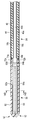
- the shaft 34 includes a cylindrical body 42 and a sheath 44 slidably disposed on the outer side of the cylindrical body 42.
- the cylindrical body 42 is fixed to the handle 32 on the proximal end side.
- the sheath 44 is slidable along the axial direction of the cylindrical body 42 by operating the first knob 32a.
- a longitudinal feed rod 46 that moves along the axial direction by the operation of the second knob 32 b is disposed inside the cylindrical body 42.
- the outer peripheral surface of the front / rear feed rod 46 and / or the inner peripheral surface of the cylindrical body 42 are insulated.
- the outer peripheral surface of the front / rear feed rod 46 is covered with an insulating tube or the like.
- the forward / reverse feed rod 46 is formed integrally with the proximal end of the rod-shaped electrode 66 through the inside of the cylindrical body 42.
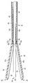
- the rod-shaped electrode 66 is moved through the front / rear feed rod 46 as shown in FIGS. 4A and 4B. It protrudes from the front-end
- the rod-shaped electrode 66 disposed between the first and second holding members 62, 64 via the front / rear feed rod 46 is moved. It moves to the operator side along the axial direction. For this reason, the tip end of the rod-shaped electrode 66 is stored with respect to the tip end (treatment side end portion) of the cylindrical body 42.
- the treatment unit 36 includes a first treatment unit 52 and a second treatment unit 54.
- the first treatment section 52 includes first and second holding members (a pair of holding members) 62 and 64 that can be opened and closed with respect to each other.
- the second treatment section 54 includes a rod-shaped electrode 66 disposed between the first and second holding members 62 and 64.
- the second holding member 64 has the same structure as the first holding member 62 shown in FIGS. 5A and 5B, the structure of the first holding member 62 will be mainly described as a representative. The detailed structure of the second holding member 64 is not shown in the figure, but will be described below with appropriate reference numerals for explanation.
- the first and second holding members 62 and 64 are disposed at the tip of the shaft 34.
- the first holding member 62 integrally has a main body 62a and a base portion 62b.
- the second holding member 64 integrally includes a main body 64a and a base portion 64b.
- the distal end is the distal end with respect to the handle 32, and the bases 62b and 64b are closest to the handle 32.
- the distal side is a base end portion, and the first and second holding members 62 and 64 have longitudinal axes defined by the tip end portion and the base end portion. Grooves 92 and 94 to be described later are formed along the longitudinal axis.
- the outer surfaces of the main bodies 62a and 64a of the first holding member 62 and the second holding member 64 are formed in a smooth curved surface.
- the outer surfaces of the base portions 62b and 64b of the first holding member 62 and the second holding member 64 are also formed into smooth curved surfaces.
- the cross sections of the main bodies 62a and 64a of the holding members 62 and 64 are formed in a substantially circular shape or a substantially oval shape as a whole. Yes.
- the cross sections of the base portions 62b and 64b are formed in a cylindrical shape as a whole.
- the diameters of the base end portions of the main bodies 62a and 64a of the first and second holding members 62 and 64 are formed larger than the diameters of the first and second base portions 62b and 64b.
- steps 63 are formed between the first and second main bodies 62a and 64a and the base portions 62b and 64b, respectively.
- the tips of the sheaths 44 of the shaft 34 are brought into contact with or separated from the steps 63 by operating the first knob 32a.
- first holding member 62 and the second holding member 64 are substantially circular as a whole of the base portions 62b and 64b in a state where the second holding member 64 is closed with respect to the first holding member 62.
- the substantially elliptical outer peripheral surface is formed substantially flush with or slightly larger in diameter than the outer peripheral surface of the distal end portion of the cylindrical body 42. Therefore, the sheath 44 of the shaft 34 can be slid with respect to the cylindrical body 42, and the base portions 62 b and 64 b of the first and second holding members 62 and 64 can be covered with the tip of the sheath 44.
- the base portions 62b and 64b of the first and second holding members 62 and 64 are both of the shaft 34 by support pins 72a and 72b disposed at the tip of the cylindrical body 42 in a direction orthogonal to the axial direction of the shaft 34.
- the cylindrical body 42 is supported so as to be rotatable with respect to the distal end portion.
- These support pins 72a and 72b are disposed in parallel to each other at the tip of the cylindrical body 42.
- the first and second holding members 62, 64 can open and close the main bodies 62a, 62b of the holding members 62, 64 by rotating the bases 62b, 64b around the support pins 72a, 72b.
- the base portions 62b and 64b of the first and second holding members 62 and 64 are each opened, for example, so as to open with respect to positions where holding surfaces 82 and 84 (described later) in contact with the living tissue of the main bodies 62a and 62b are in contact with each other. It is biased by elastic members 74a and 74b such as springs. Actually, as shown in FIGS. 4A to 4C, elastic members 74 a and 74 b are disposed on the outer periphery of the support pins 72 a and 72 b disposed at the tip of the cylindrical body 42. Therefore, the base portions 62b and 64b of the first and second holding members 62 and 64 are biased in the opening direction, respectively.
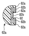
- a first holding surface 82 for holding a living tissue to be treated is formed on the side of the main body 62a of the first holding member 62 that is close to the main body 64a of the second holding member 64.
- a second holding surface 84 that holds the biological tissue to be treated is formed on the side of the first holding member 62 that is close to the main body 62a.
- the 1st holding surface 82 has the 1st contact surface 82a which contacts when hold
- the 2nd holding surface 84 has the 2nd contact surface 84a which contacts when hold
- the first and second contact surfaces 82a and 84a are formed flat. Note that the tips of the first and second contact surfaces 82a and 84a are separated from each other even when the first and second holding members 62 and 64 are closed.
- a flat plate-like first electrode 82b is disposed on the first contact surface 82a.
- a flat plate-like second electrode 84b is disposed on the second contact surface 84a.
- the first and second electrodes 82b and 84b are disposed on almost the entire surface other than the tips of the first and second contact surfaces 82a and 84a.
- the end face (side face) of the first electrode 82b and the side face of the main body 62a of the first holding member 62 are aligned.
- the end surface (side surface) of the second electrode 84b and the side surface of the main body 64a of the second holding member 64 are aligned.
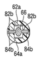
- a first groove (dent) 92 in which the rod-shaped electrode 66 is disposed is formed in the center of the contact surface 82a (first electrode 82b) of the holding surface 82 of the main body 62a of the first holding member 62.
- a second groove 94 is formed in the center of the contact surface 84a (second electrode 84b) of the holding surface 84 of the main body 64a of the second holding member 64.
- the widths of the grooves 92 and 94 of the first and second main bodies 62 a and 64 a are formed wider than the width of the rod-shaped electrode 66.
- the depths of the grooves 92 and 94 of the first and second main bodies 62 a and 64 a are formed deeper than half the height of the rod-shaped electrode 66. Therefore, when the first treatment portion 52 is closed, that is, when the first and second holding members 62 and 64 are closed, the rod-shaped electrode 66 is housed so as to be able to be taken in and out without contacting the grooves 92 and 94.
- a first electrode (high frequency electrode) 82b is also provided in the groove 92 of the first holding member 62 in order to sufficiently apply high frequency energy to the surface from which the living tissue has been removed.
- a second electrode (high frequency electrode) 84b is also disposed in the groove 94 of the second main body 64a.
- the first electrode 82b of the groove 92 of the first holding member 62 is formed to be discontinuous but at the same potential as the electrode 82b of the first contact surface 82a of the first holding member 62.
- the first electrode 84b of the groove 94 of the second holding member 64 is formed to be discontinuous but at the same potential as the electrode 84b of the second contact surface 84a of the second holding member 64.
- Elastic members 92a and 94a such as leaf springs are disposed on the back surfaces of the electrodes 82b and 84b disposed in the grooves 92 and 94.
- the elastic members 92a and 94a can be operated in conjunction with the operation of the second knob 32b.
- FIGS. 4A and 4B when the rod-shaped electrode 66 is between the main bodies 62a, 64a of the first and second holding members 62, 64, the electrode 82b disposed in the grooves 92, 94 is used. 84b are pulled into the main bodies 62a and 64a. As shown in FIG.
- the elastic members 92a and 94a are interlocked with the second knob 32b and the electrodes 82b and 84b disposed in the grooves 92 and 94, respectively. Acts to be pulled into the main bodies 62a and 64a.
- the elastic members 92a and 94a are linked to the second knob 32b and the electrodes 82b and 84b disposed in the grooves 92 and 94 are connected to the main body. It acts so as to be flush with the holding surfaces 82 and 84 of 62a and 64a.
- the electrodes 82b and 84b disposed in the grooves 92 and 94 are on the same surface as the electrodes 82b and 84b disposed on the holding surfaces 82 and 84. Therefore, the elastic members 92a and 94a release the bias of the electrodes 82b and 84b disposed in the grooves 92 and 94 in conjunction with the forward movement of the rod-shaped electrode 66, and the grooves 92 and 94 in conjunction with the backward movement.
- the electrodes 82b and 84b arranged in the above are brought into an energized state. At this time, the living tissue is also pressed by the electrodes 82b and 84b disposed in the grooves 92 and 94.
- the rod-shaped electrode 66 of the second treatment portion 54 disposed between the first and second holding members 62 and 64 is a third electrode.
- the rod-shaped electrode 66 is formed to have a smaller surface area than the sum of the surface areas of the first electrode 82b and the second electrode 84b of the first and second holding members 62 and 64. For this reason, the current density of the living tissue in contact with the surface of the rod-shaped electrode 66 is higher than the current density of the living tissue in contact with the surfaces of the first electrode 82b and the second electrode 84b. Therefore, the living tissue around the rod-shaped electrode 66 (the living tissue in the deep part) can be efficiently denatured.
- the cross section of the rod-shaped electrode 66 is formed in a circular shape, for example, but the cross section is allowed to have various shapes such as an ellipse and a polygon.
- the cross-sectional shape of the grooves 92, 94 of the holding surfaces 82, 84 formed by the first and second holding members 62, 64 is preferably the same shape as the rod-shaped electrode 66, but is circular, elliptical, Various shapes such as a polygon are allowed.
- a first energization line 18 a connected to the energy source 14 via the cable 16 extending from the handle 32 along the axial direction thereof, and the energy via the cable 16 are provided.
- a second energization line 18b connected to the source 14 is arranged.
- One end of the first energization line 18 a is electrically connected to the first electrode 82 b of the first holding member 62.
- the other end of the first energization line 18 a extends into the handle 32 through the inside of the cylindrical body 42 of the shaft 34.
- the first energization line 18 a is electrically connected to the connector 16 a through the inside of the cable 16 extending from the handle 32.
- One end of the second energization line 18 b is electrically connected to the second electrode 84 b of the second holding member 64.
- the other end of the second energization line 18 b extends into the handle 32 through the inside of the cylindrical body 42 of the shaft 34.
- the second energization line 18 b is electrically connected to the connector 16 a through the inside of the cable 16 extending from the handle 32.
- a third energization line 18c is housed inside the forward / backward feed rod 46 inside the cylindrical body 42.
- one end of the third energization line 18 c is connected to the proximal end of the longitudinal feed rod 46 inside the cylinder body 42.
- the other end of the third energization line 18 c is connected from the inside of the handle 32 to the connector 16 a through the inside of the cable 16 extending from the handle 32.
- energy can be supplied from the energy source 14 to the first electrode 82b, the second electrode 84b, and the rod-shaped electrode 66 through the connector 16a and the first to third energization lines 18a, 18b, and 18c. .
- first to third energization lines 18a, 18b, and 18c are electrically separated.
- the switching unit 28 of the energy source 14 can make the first and second energization lines 18a and 18b have the same polarity (same potential) or different polarity (different potential), and the first and second energization lines 18a, 18b, 18b and the 3rd electricity supply line 18c can be made into different poles (different electric potential). For this reason, by energizing the living tissue between the first electrode 82b and the rod-shaped electrode 66, between the second electrode 84b and the rod-shaped electrode 66, and between the first and second electrodes 82b and 84b. These biological tissues can be denatured and dehydrated.
- the first electrode 82b, the second electrode 84b, and the rod-shaped electrode 66 can perform a sensor function. That is, information on living tissue can be transmitted from the first electrode 82b, the second electrode 84b, and the rod-shaped electrode 66 to the energy source 14 through the first to third energization lines 18a, 18b, 18c and the connector 16a. it can.
- the main body 62a and the second high-frequency electrode 84b of the second holding member 64 are also formed symmetrically with the main body 62a and the first high-frequency electrode 82b of the first holding member 62. Therefore, when the second holding member 64 is closed with respect to the first holding member 62, the high-frequency electrode 82b and the second holding member 64 of the main body 62a of the first holding member 62 are shown in FIG. 4A.
- the high frequency electrodes 84b of the main body 62a are in contact with each other.
- energy high-frequency power
- the high-frequency power is supplied to the living tissue in contact with the first high-frequency electrode 82b and the second high-frequency electrode 84b and heated.
- the first and second high-frequency electrodes 82b and 84b serve as sensors, and measure the current, voltage, etc. flowing between the first and second high-frequency electrodes 82b and 84b through the living tissue, And the signal is input into the detection part 22 of the energy source 14 through the 2nd electricity supply lines 18a and 18b.
- the treatment portion 36 and the shaft 34 of the energy treatment device 12 are inserted into the abdominal cavity through the abdominal wall.
- the treatment unit 36 of the energy treatment device 12 is opposed to the biological tissue to be joined (treatment target).
- the tip of the rod-shaped electrode 66 may be inside or outside the cylindrical body 42 of the shaft 34.
- the first knob 32a of the handle 32 is operated in order to hold (grip) the living tissues to be joined by the first holding member 62 and the second holding member 64.
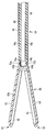
- the sheath 44 is moved to the operator side of the shaft 34 with respect to the cylindrical body 42. Due to the urging force of the elastic members 74a and 74b, the first and second base portions 64a and 64b cannot be maintained in a cylindrical shape, and the first holding member 62 and the second holding member 64 are moved relative to each other. open.
- the first holding member 62 and the second holding member 64 are simultaneously opened at the same angle with respect to the axial direction (center axis) of the shaft 34.
- the rod-shaped electrode 66 is extended with respect to the tip of the cylindrical body 42 of the shaft 34 by operating the second knob 32b.
- one side (one biological tissue) of two biological tissues to be treated is disposed between the first high-frequency electrode 82b and the rod-shaped electrode 66 of the first holding member 62, and further joined to this tissue.
- the other living tissue is disposed between the second high-frequency electrode 84 b and the rod-shaped electrode 66 of the second holding member 64. That is, the rod-shaped electrode 66 is disposed between the living tissues to be joined so as to be held by the two living tissues, and the living tissue is disposed between the first and second holding members 62 and 64.
- the first knob 32a of the handle 32 is operated.
- the sheath 44 is moved toward the distal end side of the shaft 34 with respect to the cylindrical body 42.
- the sheath 44 is closed against the urging force of the elastic members 74a and 74b, and the first and second base portions 62b and 64b are closed to form a cylinder. Therefore, the main body 62a formed integrally with the base portion 62b of the first holding member 62 and the main body 64a formed integrally with the base portion 64b of the second holding member 64 are closed. In this way, the two living tissues to be joined are held (clamped) between the first holding member 62 and the second holding member 64.
- the rod-shaped electrode 66 When joining lumen-shaped organs such as blood vessels and intestinal tracts, it is necessary to insert the rod-shaped electrode 66 into the lumen of blood vessels and intestinal tracts. It is also possible to insert the rod-shaped electrode 66 into the lumen while energizing. Further, the rod-shaped electrode 66 has a physical puncture function without applying energy. For this reason, after closing the 1st and 2nd holding members 62 and 64, the rod-shaped electrode 66 can also be arrange
- both the living tissues to be joined are in contact with both the first electrode 82b of the first holding member 62 and the second electrode 84b of the second holding member 64.
- Both the holding surface (contact surface, gripping surface) 82 of the first holding member 62 and the holding surface (contact surface, gripping surface) 84 of the second holding member 64 have peripheral tissues of living tissues to be joined. It is in close contact.
- the circuit is switched and set by the switching unit 28 so that a current flows through the living tissue between the rod-shaped electrode 66 and the first and second electrodes 82b and 84b.
- the circuit set by the switching unit 28 in this way is a first-stage output circuit.
- the rod-shaped electrode 66 has different poles with respect to the first and second electrodes 82b and 84b.
- the first and second electrodes 82b and 84b have the same polarity.
- Such an output state is referred to as a first stage output.
- the first-stage output is an output for performing a bipolar treatment in which a living tissue between the rod-shaped electrode 66 and the first and second electrodes 82b and 84b is energized for treatment.
- the impedance Z threshold is an impedance at which dehydration is completely performed so that dehydration is not performed completely, for example, 1000 [ ⁇ ] or more (see FIG. 3). Set to low (500 [ ⁇ ] as will be described later) for high impedance.
- the impedance Z of the living tissue contacting the rod-shaped electrode 66 is transferred from the rod-shaped electrode 66 to the inside of the energy source 14. Detection is performed by the detection unit 22 that receives the signal.
- the impedance Z (initial value) when treatment is started varies depending on the size (contact area) and shape of the electrodes 82b and 84b, but is about 50 [ ⁇ ], for example.
- the high frequency power is applied to the living tissue and the living tissue is cauterized, the value of the impedance Z once decreases from about 50 [ ⁇ ] and then increases.
- Such an increase in the value of impedance Z indicates that moisture has been removed from the living tissue and drying (dehydration) has progressed.
- the first stage output gives a high-frequency current between the first and second electrodes 82 b and 84 b of the first and second holding members 62 and 64 and the rod-shaped electrode 66.
- the living tissue in contact with the electrodes 82b and 84b generates heat. That is, Joule heat is generated inside the living tissue grasped between the electrodes 82b and 84b to heat the living tissue itself.
- the high frequency energy denatures proteins contained in the living tissue.
- the living tissue itself generates heat and is dehydrated. As a result, when the proteins are bound to each other, the constituent components of the living tissue are bound.
- the contact area between the first and second electrodes 82b and 84b and the living tissue is larger than the contact area of the rod-shaped electrode 66 with the living tissue.
- the contact area between the rod-shaped electrode 66 and the living tissue is smaller than the contact area of the living tissue between the first and second electrodes 82b and 84b.
- the current density with respect to the living tissue in contact with the rod-shaped electrode 66 is higher than the current density with respect to the living tissue in contact with the first and second electrodes 82b and 84b.
- the tissue component on the surface of the living tissue that is in contact with the rod-shaped electrode 66 is greatly denatured as compared with the surface of the living tissue that is in contact with the first and second electrodes 82b and 84b. Therefore, the living tissue at the joint surface between living tissues can be particularly denatured. Then, the denatured region of the living tissue is gradually expanded from the living tissue in contact with the rod-shaped electrode 66 to the deep portion of the living tissue. For this reason, the bonding force at the bonding surface between the living tissues gradually increases.
- the calculated impedance Z exceeds 500 [ ⁇ ] (not limited to this, which can be arbitrarily set) set as a threshold value in the output control unit 24, for example (S2).
- the lower impedance Z is set so as to leave room for the living tissue to be denatured without removing the moisture from the living tissues to be joined.
- the output control unit 24 stops the output of the high frequency power from the output unit 26 (S3).
- the switching unit 28 connects the energization lines 18a, 18b, and 18c that connect the output control unit 24, the energy treatment instrument 12, and the detection unit 22.
- Switch (S4) At this time, switching is performed so that the living tissue between the first electrode 82b and the second electrode 84b of the first and second holding members 62 and 64 is energized. No energy is supplied to the rod-shaped electrode 66 connected to the third energization line 18c.
- the circuit set by the switching unit 28 in this way is a second-stage output circuit. Such an output state is defined as a second stage output.
- the second-stage output is an output for performing a bipolar treatment in which the living tissue between the first and second electrodes 82b and 84b is energized for treatment.
- the second stage output starts (S5).
- the impedance Z of the living tissue is detected in the same manner as the first stage output. For example, it is determined whether the impedance has reached 500 [ ⁇ ] (S6). When the impedance Z reaches 500 [ ⁇ ], the output is stopped (S7). As described above, a low impedance Z such as 500 [ ⁇ ] is set as the threshold value so as not to drain the tissue moisture even at the output at this time.
- the living tissue between the electrode 82b of the first holding member 62 and the electrode 84b of the second holding member 64 is energized with the second stage output. For this reason, the living tissue including the joint surface between the living tissues between the first and second electrodes 82b and 84b can be uniformly denatured.
- the switching unit 28 is switched again to the same circuit as the circuit of the first stage output (S8).
- the living tissue between the rod-shaped electrode 66 and the first and second electrodes 82b and 84b is energized (S9).
- output is performed with an impedance of, for example, 1000 [ ⁇ ] as a stop condition (threshold), and the joint tissue surface is completely dehydrated (S10).
- Such an output state is defined as a third stage output.
- the third-stage output is an output for performing a bipolar type treatment in which a living tissue between the rod-shaped electrode 66 and the first and second electrodes 82b and 84b is energized. That is, it is determined whether or not the impedance Z detected by the detection unit 22 reaches 1000 [ ⁇ ], and when it reaches, the output is stopped (S11).
- the living tissue between the rod-shaped electrode 66 and the first and second electrodes 82b and 84b is again energized at the third stage output, the living tissue around the rod-shaped electrode 66 having a high current density is It can be completely dehydrated.
- the switching unit 28 is switched to the circuit of the second stage output (S12).
- the rod-shaped electrode 66 between the first and second holding members 62, 64 is retracted simultaneously (before or after) switching the switching unit 28 to the circuit of the second stage output (S12) (S13).
- the second knob 32b provided on the handle 32 is moved to the operator side, the rod-shaped electrode 66 disposed between the first and second holding members 62, 64 of the energy treatment instrument 12 is axially moved. Then, the inside of the cylindrical body 42 of the shaft 34 is moved to the operator side, and the distal end of the rod-shaped electrode 66 is stored with respect to the treatment portion 36 side end (tip) of the cylindrical body 42 of the shaft 34.
- the electrodes 82b and 84b disposed in the grooves 92 and 94 are attached to the elastic members 92a and 94a. It moves toward the holding surfaces 82 and 84 by force. Accordingly, the electrodes 82b and 84b disposed in the grooves 92 and 94 apply pressure to the living tissue. Then, pressure can be applied to the living tissue across the holding surfaces 82 and 84 of the first and second holding members 62 and 64 so as to close the space in which the rod-shaped electrode 66 is disposed, and the living bodies to be joined It can be set as the state (contact state) which joins the joint surface of tissues
- tissues can be set as the state (contact state) which joins the joint surface of tissues
- the fourth-stage output is an output for performing a bipolar treatment in which treatment is performed by energizing the living tissue between the first and second electrodes 82b and 84b.
- 1000 [ ⁇ ] is output as a stop condition (threshold) (S15).
- the biological tissue between the electrodes 82b and 84b of the first and second holding members 62 and 64 is energized to denature and dehydrate the held biological tissue.
- the detection unit 22 detects the impedance Z, and when the impedance Z reaches 1000 [ ⁇ ], the output is stopped (S16).
- the portion of the portion separated by the arrangement of the rod-shaped electrode 66 is removed. Both of them can be joined while completely removing moisture from the living tissue, that is, dehydrated. Thereafter, the treatment can be stopped.
- the living tissues to be joined are heated, and the living tissues can be gradually denatured and dehydrated to be integrated (joined and fused).
- the living tissues can be gradually denatured and dehydrated to be integrated (joined and fused).
- the switching unit 28 by switching the circuit using the switching unit 28 and outputting high-frequency energy to the living tissue, it is possible to reliably input energy to a living tissue having a thickness or a living tissue having a different composition. . Therefore, it is possible to reliably obtain the denatured and dehydrated state of the living tissue with respect to the living tissues to be joined.
- each stage output is preferably recognized by the operator by being displayed on the energy source 14 or recognized by the operator by sound (for example, a buzzer).
- termination condition (stop condition) of each stage output not only the determination as to whether or not the impedance Z has exceeded the set threshold value, but it may be terminated automatically after outputting for a certain period of time.
- the output to the living tissue between the rod-shaped electrode 66 and the first and second electrodes 82b and 84b and the detection of the living body information obtained from the living tissue are the first and second electrodes.
- 82b and 84b have the same polarity, and it is performed between the rod-shaped electrode 66 and the electrodes 82b and 84b of the first and second holding members 62 and 64.
- the output to the living tissue and the detection of the living body information are performed only on the living tissue between the rod-shaped electrode 66 and the electrode 82b of the first holding member 62, or the electrode of the rod-shaped electrode 66 and the second holding member 64.
- the output and biological information may be detected using only one of the electrodes 82b and 84b of the first and second holding members 62 and 64, such as only the biological tissue between the first and second holding members 62 and 64.
- only one side of the electrodes 82b and 84b of the first and second holding members 62 and 64 is used for output and biological information.
- high-precision control can be performed.
- the circuit is switched by the switching unit 28.
- the joining of biological tissues is achieved by protein denaturation and dehydration. That is, in order to fuse (join) living tissues with energy, it is important to denature proteins in the living tissues and to drain (dehydrate) the moisture in the living tissues. Protein denaturation and dehydration are achieved by heating the living tissue.
- a living body has tissues composed of various proteins. Since protein denaturation temperatures are different from each other, it is necessary for the joining of living tissues that are not affected by the composition of the protein to reliably raise the temperature of the living tissues.
- the living tissues to be joined held by the holding members 62 and 64 are thin, energy can be applied substantially uniformly to the held living tissues. However, when the living tissue to be joined held by the holding members 62 and 64 is thick, the joining surface at the position (the deep part) farthest from the electrodes 82b and 84b among the living tissues is given to the living tissue. In some cases, the energy density becomes low and energy is not sufficiently applied.
- the rod-shaped electrode 66 is disposed directly on the joint surface of the living tissue to be joined, and the living tissue between the electrodes 82b and 84b of the first and second holding members 62 and 64 can be energized. For this reason, high frequency energy can be concentrated on the joint surface where the rod-shaped electrode 66 is disposed (energy density can be increased). Therefore, a certain amount of energy can be reliably applied to the joint surface of the biological tissue, and the protein of the biological tissue on the joint surface can be denatured to be equal to or higher than other places. Similarly, dehydration can be performed at or above other sites. That is, it is possible to reliably control the treatment state of the joint surface.
- the protein of the biological tissue in the portion (for example, the joint surface of the biological tissue) away from the electrodes 82b and 84b provided on the holding surfaces 82 and 84 of the pair of holding members 62 and 64 can be sufficiently denatured. .
- the joining of living tissues can be achieved more stably than in the prior art, and the treatment can be performed more safely than in the prior art.
- the state of the living tissue to be joined held by the first and second holding members 62 and 64 is monitored for the impedance Z using the electrodes 82b, 84b, and 66, for the treatment.
- the electrodes 82b, 84b, 66 By switching the combination of the electrodes 82b, 84b, 66, energy can be efficiently concentrated on the joint surface of the living tissue, and the joint surface of the living tissue can be denatured and dehydrated more reliably.
- the rod-shaped electrode 66 can be rotated about its axis.
- a motor in reference numeral 43 in FIG. 1B
- the rod-shaped electrode 66 can be rotated together with the front / rear feed rod 46. it can.
- the rod-shaped electrode 66 can be rotated in this manner, the rod-shaped electrode 66 can be more easily pulled out from the living tissue bonding surface or inserted into the living tissue bonding surface by combining with the advance and retreat of the rod-shaped electrode 66. can do.
- the treatment apparatus 10 has been described with reference to FIGS. 1A to 6.
- the configuration of each unit is not limited to this, and can be replaced with any one having the same function.
- the same effect can be obtained by using, for example, a heating element that generates thermal energy by resistance heating instead of the high-frequency electrodes 82b and 84b of the holding members 62 and 64.
- the same effect can be obtained by using, for example, a heating element or ultrasonic vibration instead of the rod-shaped electrode 66.
- the output unit 26 of the energy source 14 can output any of high-frequency energy, thermal energy, and ultrasonic energy.
- the state (state) of the living tissue is detected, that is, monitored by the impedance Z, but the biological information is not limited to the impedance Z.
- the biological information is not limited to the impedance Z.
- it is allowed to use other electrical information such as power value and phase.
- the biological information include current, voltage, and power for calculating the impedance Z, impedance Z calculated from these, and phase information.
- each electrode 82b, 84b is formed in a circular shape.
- the electrodes 82b disposed in the grooves 92 are not disposed at equal intervals, but may be disposed in a state in which a part thereof is close to the axial direction.
- the electrodes 82b and 84b are continuously formed in a direction orthogonal to the longitudinal direction of the main bodies 62a and 64a.
- the contact area between the electrodes 82b and 84b and the living tissue can be increased, and the living tissue can be obtained without arranging the elastic members 92a and 94a (see FIGS. 4A to 4C). Sufficient pressure can be applied to treat.
- a second knob 32b that is separated from the first knob 32a to move the forward / reverse feed rod 46 and the rod-shaped electrode 66 with respect to the shaft 34 is used.
- the first knob 32a and the second knob 32b are arranged side by side.
- the tip of the rod-shaped electrode 66 is drawn with respect to the tip of the shaft 34, and when separated from the other end side, the rod The tip of the electrode 66 protrudes from the tip of the shaft 34 and is disposed between the first and second holding members 62 and 64.
- the linear type energy treatment device 12 for treating living tissue in the abdominal cavity (in the body) through the abdominal wall has been described as an example.
- the abdominal wall shown in FIG. It is also possible to use an open linear type energy treatment device (treatment device for treatment) 12a that takes out a living tissue to be treated through the body and performs treatment.
- the energy treatment device 12 a includes a handle 32 and a treatment unit 36. That is, unlike the energy treatment tool 12 for treating through the abdominal wall, the shaft 34 (see FIG. 1A) is removed. On the other hand, a member having the same action as that of the shaft 34 is disposed in the handle 32. For this reason, this energy treatment tool 12a can be used similarly to the energy treatment tool 12 shown to FIG. 1A mentioned above.
- a fourth electrode arranged in parallel with the rod-shaped electrode (third electrode) 66 is not shown. It is also permissible to arrange a plurality of electrodes such as the first electrode and the fifth electrode between the first and second holding members 62 and 64.
- the fourth electrode and the fifth electrode mentioned here are, for example, arranged so that the rod-shaped electrode 66 is arranged in the middle and both sides of the rod-shaped electrode 66 are sandwiched.
- the rod-shaped electrode 66 existing between the first and second holding members 62, 64 is provided with the rod-shaped electrode 66 in addition to the mechanism that can move along the axial direction of the shaft 34.
- a detachable mechanism is arranged.
- the second knob 32b of the handle 32 is provided with a separation knob 32c for separating the rod-shaped electrode 66 at the tip of a forward / backward feed tube 46a described later.
- a proximal end of a connecting rod 46b described later is connected to the second knob 32b, and a proximal end of a front / rear feed tube 46a is connected to the separation knob 32c.
- the separation knob 32c usually moves together with the second knob 32b.
- the separation knob 32c is disposed on the distal side of the operator with respect to the second knob 32b.
- a cylindrical front / rear feed tube 46 a and a connecting rod 46 b are disposed inside the cylindrical body 42 of the shaft 34 instead of the front / rear feed rod 46.
- the connecting rod 46b is disposed inside the cylindrical front / rear feed tube 46a.
- a cylindrical concave portion 66a is formed at the base end of the rod-shaped electrode 66, and the concave portion 66a is fitted to the distal end of the connecting rod 46b.
- the base end of the rod-like electrode 66 is in contact with the tip of a cylindrical front / rear feed tube 46a.
- the connecting rod 46b is made of a conductive material.
- a third energization line 18c connected to the output unit 26 of the energy source 14 is connected to the end of the connecting rod 46b on the handle 32 side.
- the front / rear feed tube 46a is preferably formed of an insulating material such as a hard plastic material. For this reason, it can energize between the electrodes 82b and 84b of the first and second holding members 62 and 64 through the living tissue from the rod-shaped electrode 66.
- the degree of fitting between the recess 66a at the proximal end of the rod-shaped electrode 66 and the distal end of the connecting rod 46b is determined when the rod-shaped electrode 66 is moved as described in the first embodiment (biological body). (Including the pushing / retracting operation for the state where the rod-shaped electrode 66 is held in the tissue), the fitting is not released.
- the connecting rod 46b remains in that position, while the forward and backward feed tube 46a moves distally relative to the operator. For this reason, the proximal end of the rod-shaped electrode 66 is pushed out to the distal end of the forward and backward feed tube 46a, and the fitting between the recessed portion 66a at the proximal end of the rod-shaped electrode 66 and the distal end of the connecting rod 46b is released. That is, the rod-shaped electrode 66 is separated from the front / rear feed tube 46a and the connecting rod 46b.
- the rod-like shape is not obtained by holding the connecting rod 46b in that position, but also by moving the connecting rod 46b to the operator side relative to the forward / backward feeding tube 46a while holding the front / rear feeding tube 46a in that position.
- the electrode 66 is separated from the front / rear feed tube 46a and the connecting rod 46b. That is, in order to separate the rod-shaped electrode 66 from the forward / backward feed tube 46a and the connecting rod 46b, the separation knob 32c is held in that position, and the second knob 32b is moved to the operator side relative to the separation knob 32c. It is also done by moving.
- the energy treatment instrument 12 having the rod-shaped electrode 66 can be used by fitting a new rod-shaped electrode 66 to the connecting rod 46b.
- elastic members 92a and 94a are arranged inside the holding members 62 and 64 as shown in FIGS. 12A to 12C.
- the elastic members 92a and 94a are electrodes 82b disposed in the grooves 92 and 94 in conjunction with the operation of disposing the second knob 32b and the separation knob 32c proximal to the operator (retracting operation of the rod-shaped electrode 66).
- 84b are energized, and the electrodes disposed in the grooves 92, 94 in conjunction with the operation of disposing the second knob 32b and the separation knob 32c distally of the operator (advancing operation of the rod-shaped electrode 66).
- the energization of 82b and 84b is released (see FIGS. 4A to 4C).
- the second knob 32b and the separation knob 32c are located at the distal side of the operator, so that the electrodes 82b and 84b disposed in the grooves 92 and 94 are provided. Has been lifted.
- the second knob 32b and the separation knob 32c may be disposed proximal to the operator.
- step (S13) of retracting the rod-shaped electrode 66 in the flowchart (see FIG. 6) of the first embodiment is removed, and the step of separating the rod-shaped electrode (probe) 66 (S18) is inserted instead. ing.
- the step of separating the rod-shaped electrode 66 (S18) is performed after the fourth stage output is stopped.
- the living tissue is held and the process is performed from the start of the first stage output (S1) to the stop of the fourth stage output (S16). Thereafter, the impedance Z of the living tissue between the electrodes 82b and 84b of the first and second holding members 62 and 64 and the rod-shaped electrode 66 is detected (S17).
- the electrode 82b of the first and second holding members 62, 64 is again provided as the fifth stage output. , 84b and the rod-shaped electrode 66 are energized for treatment (S19).
- output is performed with an impedance of 1000 [ ⁇ ], for example, as a stop condition (threshold) (S20).
- Such an output state is defined as a fifth stage output. That is, it is determined whether or not the impedance Z detected by the detection unit 22 reaches 1000 [ ⁇ ], and when it reaches, the output is stopped (S21).
- the dehydrated living tissue can be more completely performed. This is because a phenomenon may occur in which moisture returns to the living tissue during the output of the fourth stage output or after the stop of the fourth stage output.
- the living tissue between the electrodes 82b and 84b of the first and second holding members 62 and 64 is energized by the fourth-stage output or the fifth-stage output, the living tissue including the living tissue in contact with the rod-shaped electrode 66 is obtained.
- the joint surface between them is denatured and dehydrated.
- the rod-shaped electrode 66 disposed between the holding members 62 and 64 is cut off. As a result, the rod-shaped electrode 66 is cut off. That is, the rod-shaped electrode 66 is placed on the joint surface between living tissues.
- the rod-shaped electrode 66 Even if the rod-shaped electrode 66 is placed in this manner, the bonded surfaces of the living tissues including the living tissue in contact with the rod-shaped electrodes 66 are denatured and dehydrated, so that the bonded surfaces can be maintained. Further, it is possible to prevent peeling of the joint surface by removing the rod-shaped electrode 66 from the joint surface of the living tissue.
- the fourth stage output is stopped, the impedance Z of the joint surface is detected again, and if necessary, the fifth stage output is performed on the joint surface between the living tissues. For this reason, dehydration of the living tissue can be performed more completely.
- the rod-shaped electrode 66 is placed on the joint surface between the living tissues, it is not necessary to consider the removal of the rod-shaped electrode 66, so the holding surfaces 82, 84 of the first and second holding members 62, 64.
- the electrodes 82b and 84b provided in the grooves 92 and 94 can apply pressure to the joint surface of the living tissue. For this reason, living tissue can be joined more strongly.
- the electrodes 82b and 84b are the main bodies. It is also preferable that they are continuously formed in a direction orthogonal to the longitudinal direction of 62a and 64a.
- the electrodes 82b and 84b it is possible to treat a living tissue without arranging elastic members 92a and 94a (see FIGS. 12A to 12C) on the holding members 62 and 64 shown in FIGS. 14A to 14D. Sufficient pressure can be applied.
- FIGS. 15 to 18 A third embodiment will be described with reference to FIGS. 15 to 18. This embodiment is a modification of the first embodiment.
- the same members as those described in the first embodiment are denoted by the same reference numerals, and detailed description thereof is omitted.
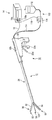
- the treatment apparatus 10 includes a treatment unit 36 in addition to an energy treatment tool (handpiece, treatment tool) 12 and an energy source 14 that transmits high-frequency energy to the energy treatment tool 12.
- a fluid supply unit 102 for supplying a fluid such as physiological saline is provided.
- the fluid supply unit 102 includes a bag 112 containing physiological saline, a water supply tube (fluid supply tube) 114 having a rear end connected to the bag 112, and an inner diameter of the water supply tube 114. And a flow rate adjusting device (fluid control unit) 116 for controlling the supply amount of physiological saline supplied from.
- the fluid (fluid) stored in the bag 112 it is preferable to use a fluid that is permeable to living tissue and that can induce electrical energy, such as an ionized conductive fluid.
- a fluid for example, physiological saline, hypertonic saline, hypotonic saline, electrolyte replenishment preparation and the like are used.
- a glue such as hyaluronic acid having high viscosity as a fluid is allowed. When the glue is used, it penetrates when the glue is applied to the biological tissue to be treated, but the glue is prevented from flowing to the living tissue around the biological tissue to be treated.
- the water supply tube 114 extends from the handle 32 of the energy treatment device 12 in the same manner as the cable 16.
- the flow control device 116 is detachably connected to the energy source 14 by a cable 118 and a connector 118a disposed at an end thereof.
- the flow control device 116 closes the flow path of the water supply tube 114 by applying pressure to the water supply tube 114 from the outside and supplies the physiological saline from the bag 112.
- the pressure from the outside to the water supply tube 114 is removed, and the flow path of the water supply tube 114 is opened by elastic deformation of the water supply tube 114. That is, the flow control device 116 can mechanically open and close the flow path of the water supply tube 114.
- the flow control device 116 is connected to a foot switch and a hand switch (not shown) for opening and closing the flow path of the water supply tube 114. For example, if the state where the foot switch or the hand switch is released is maintained, the supply of the physiological saline to the energy treatment device 12 is stopped. On the other hand, when the foot switch or the hand switch is kept pressed, a physiological saline solution having a controlled flow rate is supplied to the energy treatment device 12 through the water supply tube 114, and then the flow path of the water supply tube 114 is automatically blocked. The supply of saline is automatically stopped.
- the controlled flow rate is a predetermined flow rate, a flow of fluid (saline) for a predetermined time, or a fluid (saline) appropriately according to the output of the second stage output or the like.
- Various controls such as supply can be performed by setting.
- a flow rate adjustment knob 32d is provided in parallel with the first knob 32a.
- the flow rate adjusting knob 32d is used to control the flow rate adjusting device 116 so as to forcibly open or close.
- the distal end of the water supply tube 114 is connected to the proximal end of the front / rear feed tube 46a shown in FIGS. 17A to 17C.
- the rear end of the front / rear feed tube 46 a is connected to the second knob 32 b of the handle 32. For this reason, the front / rear feed tube 46a advances and retreats in the cylindrical body 42 of the shaft 34 by operating the second knob 32b.
- the proximal end of a tubular electrode 122 having a flow path 122a is fitted and connected to the distal end of the front / rear feed tube 46a.
- the distal end of the third energization line 18 c is connected to the proximal end of the tubular electrode 122.
- the third energization line 18c extends to the handle 32 side through the inside of the front / rear feed tube 46a, and extends outward from the front / rear feed tube 46a in the handle 32, together with the first and second energization lines 18a, 18b. Arranged in the cable 16.
- the tube-shaped electrode 122 is formed by forming the rod-shaped electrode (high-frequency electrode) 66 described in the first and second embodiments into a cylindrical shape. For this reason, the tubular electrode 122 has a function of discharging a liquid to a living tissue that may exist between the first and second holding members 62 and 64.
- the handle 32 is provided with a second knob (electrode advance / retreat knob with a liquid discharge portion) 32b.
- the second knob 32 b is provided with a front / rear feed tube 46 a instead of the front / rear feed rod 46.
- the distal end of the front / rear feed tube 46 a is connected to the proximal end of the tubular electrode 122 through the inside of the cylindrical body 42 of the shaft 34.
- a third energization line 18c is inserted inside the front / rear feed tube 46a.
- a tubular electrode 122 is disposed between the first and second holding members 62 and 64.
- the tubular electrode 122 advances and retracts between a state in which it is disposed between the first and second holding members 62 and 64 (the tubular electrode 122 is projected) and a state in which it is disposed inside the shaft 34.
- the tip when the tubular electrode 122 is projected is set at a position that does not exceed the most distal electrodes 82b and 84b among the electrodes 82b and 84b of the first and second holding members 62 and 64.
- the width (outer diameter) of the tubular electrode 122 is narrower than the electrodes 82b and 84b of the first and second holding members 62 and 64. For this reason, energy can be applied only to the surface of the living tissue to which energy is applied by the electrodes 82b and 84b of the first and second holding members 62 and 64.
- the cross-sectional shape (outer shape) of the tubular electrode 122 is formed in a circular shape, for example, but the outer shape of the cross section is allowed to have various shapes such as an ellipse and a polygon.
- the cross-sectional shape of the grooves 92 and 94 of the holding surfaces 82 and 84 is preferably the same shape as the outer shape of the tubular electrode 122, but various shapes such as a circle, an ellipse, and a polygon are allowed. Is done.
- the fluid physiological saline
- the tube-shaped electrode 122 has other numbers of liquid discharge portions (small holes) 122b having a diameter of 1 mm or less. For this reason, the fluid can be supplied to the joint surface of the living tissue substantially uniformly.
- the process is performed from the first stage output to the fourth stage output.
- the rod-shaped electrode 66 described in the first embodiment is retracted simultaneously with the circuit switching (S12) from the stop of the third stage output (S11) to the start of the fourth stage output (S14). Instead, the tubular electrode 122 is retracted (S33).
- physiological saline is injected between the stop of the first stage output (S3) and the start of the second stage output (S5) (S31) and the second stage output.
- Saline is injected between the stop (S7) and the start of the third stage output (S9) (S32).
- the physiological saline is released from the tubular electrode 122 through the water supply tube 114 and the front / rear feed tube 46a by operating a foot switch or a hand switch (not shown) connected to the flow rate adjusting device 116 of the fluid supply unit 102. . That is, the physiological saline is directly released to the joint surface of the living tissue to be joined.
- the impedance Z of the living tissue between the electrodes 82b and 84b is lowered.
- the impedance Z By reducing the impedance Z, more energy can be administered to the living tissues to be joined. That is, it is possible to easily denature proteins in living tissue.
- the fluid discharge amount is set in advance by the output control unit 24, for example.
- Release of the physiological saline from the tubular electrode 122 can be performed before and after the output of the tubular electrode 122 or simultaneously. Similarly, the physiological saline can be released from the tubular electrode 122 before energization of the living tissue between the electrodes 82b and 84b of the holding members 62 and 64, or simultaneously.
- the rod-shaped electrode 66 is disposed on the joint surface of the living tissue held by the holding members 62 and 64.
- One of the effects is that not only the current from the electrodes 82b and 84b of the holding members 62 and 64 but also the current can be directly applied to the joint surface of the living tissue, whereby the joint surface can be denatured and dehydrated. Is.
- a tubular electrode 122 is provided that can energize the living tissue between the first and second electrodes 82b and 84b and can supply fluid to the joint surface of the held living tissue. .
- the impedance Z of the living tissue between the holding members 62 and 64 can be lowered after the first stage output. For this reason, it becomes possible to input more energy into the living tissues to be joined. As a result, more energy can be input to the joint surface.
- the conductive fluid physiological saline
- a chemical solution or the like necessary for treatment of a living tissue may be supplied.
- the energization to the tube-shaped electrode 122, the release of the fluid to the living tissue, the retraction of the tube-shaped electrode 122, and the energization to the living tissue between the holding members 62 and 64 are performed manually. Although the case has been described, a series of operations can be set to be performed automatically.
- a plurality of tubular electrodes 122 can be arranged like the above-described fourth and fifth electrodes.
- FIGS. 19A to 19C a fourth embodiment will be described with reference to FIGS. 19A to 19C.
- This embodiment is a modification of the first to third embodiments.
- the same members as those described in the first to third embodiments are denoted by the same reference numerals, and detailed description will be given. Omitted.
- the first and second holding members 62 and 64 have a structure capable of discharging a fluid.
- the main body 62a of the first holding member 62 is provided with an electrode 132 having a planar contact surface with a living tissue.
- the electrode 132 is formed in a substantially rectangular shape, and an annular groove 134 serving as a passage for vapor generated from living tissue is formed on the outer periphery of the electrode 132.
- a pipe line 136 is disposed inside the main body 62 a of the first holding member 62.
- the pipe 136 is bent in a substantially L shape inside the main body 62a of the first holding member 62, and a plurality of openings (through holes) 136a are formed.
- the plurality of openings 136 a are opened on the surface of the electrode 132. That is, the pipe line 136 and the outside of the electrode 132 are in communication.
- the plurality of openings 136a opened by the electrodes 132 are formed with the same diameter at predetermined intervals, for example, at positions deviated from the central axis of the main body 62a of the first holding member 62 by a predetermined distance. For this reason, when a fluid such as physiological saline is passed through the conduit 136, the fluid is discharged from the opening 136a of the conduit 136.
- the openings 136a are arranged at equal intervals in positions substantially parallel to the groove 92 formed on the central axis of the main body 62a of the first holding member 62.
- the outer periphery of the opening 136a is covered with an insulating material.
- the pipe 136 itself is formed of an insulating material.
- the pipe 136 is preferably, for example, a cylinder or a square cylinder, but the cross section is allowed to have various shapes such as an elliptic cylinder and a polygonal cylinder.
- the pipe 136 is formed continuously to the handle 32 through the inside of the cylindrical body 42 of the shaft 34 or the outside of the shaft 34.
- the pipe line 136 communicates with the water supply tube 114, and the physiological saline supplied from the bag 112 through the water supply tube 114 is not only the tubular electrode 122 but also the electrodes 132 and 142 of the first and second holding members 62 and 64. It can discharge also from the opening part 136a arrange
- the electrode 132 is disposed on the cable 16 extended from the handle 32 via the first energization line 18a at the base end opposite to the side facing the second holding member 64, for example. .
- the second holding member 64 is also formed symmetrically with the first holding member 62.
- the electrode provided on the second holding member 64 is denoted by reference numeral 142
- the annular groove is denoted by reference numeral 144
- the conduit is denoted by reference numeral 146
- the opening is denoted by reference numeral 146a.
- the electrodes 132 and 142 of the first and second holding members 62 and 64 When energy (high frequency power) is supplied from the energy source 14 when the electrodes 132 and 142 of the first and second holding members 62 and 64 have the same potential (same polarity), the electrodes of the first holding member 62 High-frequency energy is supplied to the living tissue in contact with 132 and the electrode 142 of the second holding member 64 and heated. At this time, the electrodes 132 and 142 serve as sensors, measure currents, voltages and the like flowing between the electrodes 132 and 142 through the living tissue, and pass through the first and second energization lines 18a and 18b. The signal is input to the detector 22.
- the pipe lines 136 and 146 of the first and second holding members 62 and 64 extend to the handle 32 through the inside of the cylindrical body 42 of the shaft 34.
- These pipes 136 and 146 extend from the handle 32 as tubes (not shown) arranged in parallel with the first and second energization lines 18a and 18b, and are connected to a water supply tube 114 (see FIG. 15) and the like. Yes. Therefore, a liquid such as a conductive fluid can be injected into the openings 136a and 146a through the pipes 136 and 146.
- openings 136a and 146a are each formed in a circular shape in FIGS. 19A to 19C, but are not limited to a circular shape, and various shapes such as an ellipse and a polygon are allowed.
- the arrangement of the opening 136a in the first holding member 62 and the arrangement of the opening 146a in the second holding member 64 are arranged in the vertical direction (longitudinal direction) in the first and second high-frequency electrodes 132 and 142.
- FIGS. 20A to 21 a fifth embodiment will be described with reference to FIGS. 20A to 21.
- This embodiment is a modification of the first to fourth embodiments.
- the same members as those described in the first to fourth embodiments are denoted by the same reference numerals, and detailed description will be given. Omitted.
- the energy treatment device 12 includes a mechanism for moving the tubular electrode 122 described in the third embodiment, and a second embodiment.
- a mechanism capable of separating the rod-shaped electrode 66 described is provided. That is, the energy treatment device 12 according to this embodiment is provided with a mechanism capable of separating the tubular electrode 122.
- the mechanism capable of separating the tubular electrode 122 shown in FIGS. 20A to 20C is roughly the same as the mechanism capable of separating the rod-shaped electrode 66 described in the second embodiment.
- a longitudinal feed tube 46 a and a connection tube 46 c are disposed inside the cylindrical body 42 of the shaft 34.
- a connection tube 46c is provided instead of the connection rod 46b in order to allow fluid to flow.
- a tube-shaped electrode 122 is disposed at the distal ends of the front-rear feed tube 46a and the connection tube 46c, instead of the rod-shaped electrode 66 of the second embodiment.
- the tip of the third energization line 18c is fixed inside the tip of the connection tube 46c and extends to the handle 32 side.
- the operation of the treatment apparatus 10 is shown in the flowchart shown in FIG. This is a combination of the flow described with reference to FIG. 18 in the third embodiment in addition to the flow described with reference to FIG. 13 in the second embodiment.
- FIG. 22 and 23 A sixth embodiment will be described with reference to FIGS. 22 and 23.
- FIG. This embodiment is a modification of the third and fifth embodiments.
- the same members as those described in the third and fifth embodiments are denoted by the same reference numerals, and detailed description will be given. Omitted.
- a liquid discharge nozzle 152 having a flow path 152 a is arranged instead of the tubular electrode 122. Therefore, as shown in FIG. 22, the third energization line 18 c (see FIGS. 2 and 16) is not connected to the nozzle 152. That is, the third energization line 18 c is removed from the cable 16. For this reason, the electrodes 82b and 84b provided on the first and second holding members 62 and 64 are used to join the living tissues together. Further, in this embodiment, as shown in FIG. 22, the switching unit 28 is provided, but in this embodiment, there is no need to switch the circuit. That is, the switching unit 28 may not be provided.
- the first treatment section 52 of the treatment section 36 of the energy treatment device 12 includes a pair of holding members 62 and 64 that can be opened and closed, and the second treatment section 54 is a liquid discharge nozzle. 152 is provided.
- the liquid discharge nozzle 152 can discharge the fluid (saline) not only from the tip of the liquid discharge nozzle 152 but also from the side surface of the liquid discharge nozzle 152. That is, for example, the liquid discharge nozzle 152 is formed with other numbers of liquid discharge holes 152b having a diameter of 1 mm or less. For this reason, the fluid can be supplied to the joint surface of the living tissue substantially uniformly.
- the second knob 32b (see FIG. 15) provided on the handle 32 functions as an advance / retreat knob of the liquid discharge nozzle 152.
- the second knob 32 b is connected to, for example, the outer wall of the water supply tube 114 inside the handle 32.
- the water supply tube 114 is moved to the operator side.
- the liquid discharge nozzle 152 connected to the tip of the water supply tube 114 moves to the operator side and is stored inside the shaft 34.
- the living tissue is held between the holding surfaces 82 and 84 of the first and second holding members 62 and 64. At this time, the liquid discharge nozzle 152 is disposed between the joint surfaces of the living tissue. That is, the liquid discharge nozzle 152 is sandwiched between living tissues.
- the foot switch or hand switch connected to the energy source 14 is operated.
- the biological tissue between the first electrode 82b and the second electrode 84b of the first and second holding members 62 and 64 is energized from the energy source 14 (S41).
- the protein of the biological tissue held by the holding members 62 and 64 is denatured and the biological tissue is dehydrated at the same time.
- the impedance Z is calculated by the detection unit 22 of the energy source 14 through the electrodes 82b and 84b.
- the output control unit 24 stops the output of the high-frequency power from the output unit 26 (S43).
- physiological saline is discharged from the liquid discharge nozzle 152 through the water supply tube 114 (S44). Since a large number of liquid discharge holes 152b are formed in the nozzle 152, the physiological saline is discharged to the joint surface of the living tissue to be joined.
- the foot switch or the hand switch is operated (the pressed state is released) or the physiological saline is discharged at a predetermined flow rate, the release of the physiological saline is stopped.
- the discharge amount can also be set in advance by the flow rate adjusting device 116, for example.
- the tip of the liquid discharge nozzle 152 disposed in close contact with the joint surface is retracted to the inside of the shaft 34 (S45).
- the electrodes 82b and 84b disposed in the grooves 92 and 94 of the first and second holding members 62 and 64 are provided inside the main bodies 62a and 64a of the first and second holding members 62 and 64, respectively.
- the elastic members 92a and 94b are urged so that the joint surfaces of the living tissue come into close contact with each other.
- the foot switch or the hand switch connected to the energy source 14 is operated again with the impedance of, for example, 1000 [ ⁇ ] as a stop condition (threshold).
- the living tissue between the first electrode 82b and the second electrode 84b of the first and second holding members 62 and 64 is energized from the energy source 14 (S46).
- the protein of the biological tissue held by the holding members 62 and 64 is denatured and the biological tissue is dehydrated at the same time.
- the impedance Z is calculated by the detection unit 22 of the energy source 14 through the electrodes 82b and 84b.
- output is performed with an impedance of 1000 [ ⁇ ], for example, as a stop condition (threshold), and the joint tissue surface is completely dehydrated (S47). That is, it is determined whether or not the impedance Z detected by the detection unit 22 reaches 1000 [ ⁇ ], and when it reaches, the output is stopped (S48). For this reason, the site
- the first output (S41-S43), the physiological saline injection (S44), and the second output (S46-S48) were performed manually, but it is also possible to set these series of operations to be performed automatically. .
- Release of the physiological saline from the liquid discharge nozzle 152 can be performed before the output of the electrodes 82b and 84b of the holding members 62 and 64, or can be performed simultaneously. In that case, the nozzle 152 is moved backward after the second output is stopped.
- the rod-shaped electrode 66 is disposed on the joint surface of the held biological tissue.
- the effect is that not only the current from the electrodes 82b and 84b of the holding members 62 and 64 but also the current is directly applied to the joint surface of the living tissue to denature and dehydrate the joint surface.
- the liquid discharge nozzle 152 capable of injecting physiological saline is provided on the joint surface of the held biological tissue.
- the impedance Z of the joint surface can be reduced by injecting physiological saline after energizing the whole living tissue to be joined held by the first and second holding members 62 and 64. For this reason, it can energize again to the joint surface of living tissue. As a result, more energy can be input to the bonding surfaces, and the living tissues can be strongly bonded to each other.
- FIGS. 24A to 24C a seventh embodiment will be described with reference to FIGS. 24A to 24C.
- This embodiment is a modification of the sixth embodiment.
- the same members as those described in the sixth embodiment are denoted by the same reference numerals, and detailed description thereof is omitted.
- the separation mechanism is the same as that described in the second and fifth embodiments, the description thereof is omitted.
- the rod-shaped electrode 66 of the second embodiment is replaced with a liquid discharge nozzle 152 in the present embodiment.
- DESCRIPTION OF SYMBOLS 10 ... Treatment apparatus, 12 ... Energy treatment tool, 14 ... Energy source, 16 ... Cable, 18a ... 1st electricity supply line, 18b ... 2nd electricity supply line, 18c ... 3rd electricity supply line, 22 ... Detection part, 24 ... Output control unit, 26 ... Output unit, 28 ... Switching unit, 36 ... Treatment unit, 52 ... First treatment unit, 54 ... Second treatment unit, 62 ... First holding member, 64 ... Second Holding member, 66 ... rod-shaped electrode, 82 ... first holding surface, 82b ... first electrode, 84 ... second holding surface, 84b ... second electrode
Landscapes
- Health & Medical Sciences (AREA)
- Surgery (AREA)
- Engineering & Computer Science (AREA)
- Life Sciences & Earth Sciences (AREA)
- Biomedical Technology (AREA)
- Otolaryngology (AREA)
- Nuclear Medicine, Radiotherapy & Molecular Imaging (AREA)
- Plasma & Fusion (AREA)
- Physics & Mathematics (AREA)
- Heart & Thoracic Surgery (AREA)
- Medical Informatics (AREA)
- Molecular Biology (AREA)
- Animal Behavior & Ethology (AREA)
- General Health & Medical Sciences (AREA)
- Public Health (AREA)
- Veterinary Medicine (AREA)
- Surgical Instruments (AREA)
Priority Applications (3)
| Application Number | Priority Date | Filing Date | Title |
|---|---|---|---|
| JP2010527275A JP4801220B2 (ja) | 2009-01-21 | 2009-12-22 | 治療処置装置および治療用処置具 |
| CN200980155177.6A CN102292045B (zh) | 2009-01-21 | 2009-12-22 | 治疗处理装置及治疗用处理器具 |
| EP09838873.9A EP2380515A4 (en) | 2009-01-21 | 2009-12-22 | TREATMENT DEVICE AND TREATMENT TOOL |
Applications Claiming Priority (2)
| Application Number | Priority Date | Filing Date | Title |
|---|---|---|---|
| US12/356,767 | 2009-01-21 | ||
| US12/356,767 US20100185196A1 (en) | 2009-01-21 | 2009-01-21 | Medical treatment apparatus, treatment instrument and treatment method for living tissue using energy |
Publications (1)
| Publication Number | Publication Date |
|---|---|
| WO2010084683A1 true WO2010084683A1 (ja) | 2010-07-29 |
Family
ID=42337533
Family Applications (1)
| Application Number | Title | Priority Date | Filing Date |
|---|---|---|---|
| PCT/JP2009/071275 Ceased WO2010084683A1 (ja) | 2009-01-21 | 2009-12-22 | 治療処置装置および治療用処置具 |
Country Status (5)
| Country | Link |
|---|---|
| US (1) | US20100185196A1 (https=) |
| EP (1) | EP2380515A4 (https=) |
| JP (2) | JP4801220B2 (https=) |
| CN (1) | CN102292045B (https=) |
| WO (1) | WO2010084683A1 (https=) |
Cited By (1)
| Publication number | Priority date | Publication date | Assignee | Title |
|---|---|---|---|---|
| WO2017018205A1 (ja) * | 2015-07-24 | 2017-02-02 | オリンパス株式会社 | エネルギー処置システム、エネルギー制御装置及びエネルギー処置具 |
Families Citing this family (48)
| Publication number | Priority date | Publication date | Assignee | Title |
|---|---|---|---|---|
| US8500735B2 (en) * | 2008-04-01 | 2013-08-06 | Olympus Medical Systems Corp. | Treatment method for living tissue using energy |
| US8500736B2 (en) * | 2008-04-01 | 2013-08-06 | Olympus Medical Systems Corp. | Treatment method for living tissue using energy |
| WO2013088892A1 (ja) * | 2011-12-12 | 2013-06-20 | オリンパスメディカルシステムズ株式会社 | 処置システム及び処置システムの制御方法 |
| JP5425344B2 (ja) * | 2011-12-12 | 2014-02-26 | オリンパスメディカルシステムズ株式会社 | 処置システム及び処置システムの作動方法 |
| WO2013088890A1 (ja) * | 2011-12-12 | 2013-06-20 | オリンパスメディカルシステムズ株式会社 | 処置システムおよび処置システムの制御方法 |
| CN105012012B (zh) * | 2012-03-19 | 2017-12-29 | 奥林巴斯株式会社 | 把持处理装置 |
| CN104135955B (zh) * | 2012-04-20 | 2016-10-19 | 奥林巴斯株式会社 | 手术装置 |
| WO2013157408A1 (ja) * | 2012-04-20 | 2013-10-24 | オリンパスメディカルシステムズ株式会社 | 手術装置 |
| US9039691B2 (en) | 2012-06-29 | 2015-05-26 | Covidien Lp | Surgical forceps |
| US9072524B2 (en) | 2012-06-29 | 2015-07-07 | Covidien Lp | Surgical forceps |
| CN104736088A (zh) * | 2012-11-09 | 2015-06-24 | 奥林巴斯医疗株式会社 | 治疗处理器具及治疗处理方法 |
| JP5988868B2 (ja) * | 2012-12-27 | 2016-09-07 | オリンパス株式会社 | 治療用処置装置 |
| JP5677633B2 (ja) * | 2013-01-10 | 2015-02-25 | 学校法人慶應義塾 | 手術用高周波電気外科用処置具と手術用高周波電気外科用システム |
| JP5988885B2 (ja) * | 2013-01-30 | 2016-09-07 | オリンパス株式会社 | 治療用処置装置 |
| US9597141B2 (en) | 2013-09-03 | 2017-03-21 | Covidien Lp | Switch assemblies for multi-function surgical instruments and surgical instruments incorporating the same |
| US9713492B2 (en) | 2013-09-03 | 2017-07-25 | Covidien Lp | Switch assemblies for multi-function surgical instruments and surgical instruments incorporating the same |
| US9579117B2 (en) | 2013-09-25 | 2017-02-28 | Covidien Lp | Multi-function surgical instruments |
| US9987071B2 (en) * | 2013-12-02 | 2018-06-05 | Covidien Lp | Surgical instrument with end-effector assembly including three jaw members |
| US9987035B2 (en) * | 2013-12-02 | 2018-06-05 | Covidien Lp | Surgical instrument with end-effector assembly including three jaw members and methods of cutting tissue using same |
| US9987075B2 (en) * | 2013-12-02 | 2018-06-05 | Covidien Lp | Surgical instrument with end-effector assembly including three jaw members |
| EP3087939A4 (en) * | 2013-12-27 | 2017-09-27 | Olympus Corporation | Treatment tool |
| US10231776B2 (en) | 2014-01-29 | 2019-03-19 | Covidien Lp | Tissue sealing instrument with tissue-dissecting electrode |
| US9895160B2 (en) | 2014-04-16 | 2018-02-20 | Gyrus Acmi Inc. | Surgical operating apparatus with temperature control |
| WO2016031382A1 (ja) * | 2014-08-26 | 2016-03-03 | オリンパス株式会社 | 電気外科処置システム |
| US10039593B2 (en) | 2014-09-17 | 2018-08-07 | Covidien Lp | Surgical instrument having a bipolar end effector assembly and a deployable monopolar assembly |
| US9987076B2 (en) | 2014-09-17 | 2018-06-05 | Covidien Lp | Multi-function surgical instruments |
| US9918785B2 (en) | 2014-09-17 | 2018-03-20 | Covidien Lp | Deployment mechanisms for surgical instruments |
| US10080605B2 (en) | 2014-09-17 | 2018-09-25 | Covidien Lp | Deployment mechanisms for surgical instruments |
| US10039592B2 (en) | 2014-09-17 | 2018-08-07 | Covidien Lp | Deployment mechanisms for surgical instruments |
| US9814517B2 (en) | 2014-11-17 | 2017-11-14 | Covidien Lp | Deployment mechanisms for multi-function surgical instruments |
| US9724153B2 (en) | 2014-11-17 | 2017-08-08 | Covidien Lp | Deployment mechanisms for surgical instruments |
| US9867656B2 (en) | 2014-11-17 | 2018-01-16 | Covidien Lp | Multi-function surgical instruments |
| US9814516B2 (en) | 2014-11-17 | 2017-11-14 | Covidien Lp | Deployment mechanisms for multi-function surgical instruments |
| US9687294B2 (en) | 2014-11-17 | 2017-06-27 | Covidien Lp | Deployment mechanism for surgical instruments |
| US9687293B2 (en) | 2014-11-17 | 2017-06-27 | Covidien Lp | Deployment mechanism for surgical instruments |
| US10478245B2 (en) | 2014-12-10 | 2019-11-19 | Covidien Lp | Energizable attachment for surgical devices |
| DE112015006004T5 (de) * | 2015-02-27 | 2017-10-26 | Olympus Corporation | Medizinische Behandlungsvorrichtung, Verfahren zum Bedienen einer medizinischen Behandlungsvorrichtung und Behandlungsverfahren |
| US10206736B2 (en) | 2015-03-13 | 2019-02-19 | Covidien Lp | Surgical forceps with scalpel functionality |
| USD844139S1 (en) | 2015-07-17 | 2019-03-26 | Covidien Lp | Monopolar assembly of a multi-function surgical instrument |
| USD844138S1 (en) | 2015-07-17 | 2019-03-26 | Covidien Lp | Handle assembly of a multi-function surgical instrument |
| US10537381B2 (en) | 2016-02-26 | 2020-01-21 | Covidien Lp | Surgical instrument having a bipolar end effector assembly and a deployable monopolar assembly |
| JPWO2018078797A1 (ja) * | 2016-10-28 | 2019-09-05 | オリンパス株式会社 | 医療用処置装置、及び医療用処置装置の作動方法 |
| US11154348B2 (en) | 2017-08-29 | 2021-10-26 | Covidien Lp | Surgical instruments and methods of assembling surgical instruments |
| US11123132B2 (en) | 2018-04-09 | 2021-09-21 | Covidien Lp | Multi-function surgical instruments and assemblies therefor |
| CN108523985B (zh) * | 2018-04-23 | 2024-05-07 | 南微医学科技股份有限公司 | 一种多功能高频电切开刀 |
| US10828756B2 (en) | 2018-04-24 | 2020-11-10 | Covidien Lp | Disassembly methods facilitating reprocessing of multi-function surgical instruments |
| US11896291B2 (en) | 2018-07-02 | 2024-02-13 | Covidien Lp | Electrically-insulative shafts, methods of manufacturing electrically-insulative shafts, and energy-based surgical instruments incorporating electrically-insulative shafts |
| JP7459311B2 (ja) * | 2021-01-25 | 2024-04-01 | オリンパスメディカルシステムズ株式会社 | 処置具 |
Citations (5)
| Publication number | Priority date | Publication date | Assignee | Title |
|---|---|---|---|---|
| US6500176B1 (en) | 2000-10-23 | 2002-12-31 | Csaba Truckai | Electrosurgical systems and techniques for sealing tissue |
| JP2005534451A (ja) * | 2002-08-07 | 2005-11-17 | アドバンスト メディカル アプリケーションズ インコーポレーテッド | 超音波創傷清浄化装置及び方法 |
| JP2007229270A (ja) | 2006-03-01 | 2007-09-13 | Tokyo Medical & Dental Univ | 生体組織接着装置 |
| JP2008055151A (ja) * | 2006-08-30 | 2008-03-13 | Olympus Medical Systems Corp | 手術用処置装置及び、手術用処置装置の駆動方法 |
| JP2008212679A (ja) * | 2007-02-28 | 2008-09-18 | Olympus Medical Systems Corp | 手術用処置装置 |
Family Cites Families (10)
| Publication number | Priority date | Publication date | Assignee | Title |
|---|---|---|---|---|
| US5599346A (en) * | 1993-11-08 | 1997-02-04 | Zomed International, Inc. | RF treatment system |
| US6464702B2 (en) * | 2001-01-24 | 2002-10-15 | Ethicon, Inc. | Electrosurgical instrument with closing tube for conducting RF energy and moving jaws |
| JP3967560B2 (ja) * | 2001-04-19 | 2007-08-29 | ペンタックス株式会社 | 内視鏡用バイポーラ高周波処置具 |
| US7354440B2 (en) * | 2001-10-22 | 2008-04-08 | Surgrx, Inc. | Electrosurgical instrument and method of use |
| US6736814B2 (en) * | 2002-02-28 | 2004-05-18 | Misonix, Incorporated | Ultrasonic medical treatment device for bipolar RF cauterization and related method |
| US8905977B2 (en) * | 2004-07-28 | 2014-12-09 | Ethicon Endo-Surgery, Inc. | Surgical stapling instrument having an electroactive polymer actuated medical substance dispenser |
| US20060235378A1 (en) * | 2005-04-18 | 2006-10-19 | Sherwood Services Ag | Slider control for ablation handset |
| WO2008147773A1 (en) * | 2007-05-22 | 2008-12-04 | Schechter David A | Apparatus for attachment and reinforcement of tissue, apparatus for reinforcement of tissue, methods of attaching and reinforcing tissue, and methods of reinforcing tissue |
| US8226639B2 (en) * | 2008-06-10 | 2012-07-24 | Tyco Healthcare Group Lp | System and method for output control of electrosurgical generator |
| US8852179B2 (en) * | 2008-10-10 | 2014-10-07 | Covidien Lp | Apparatus, system and method for monitoring tissue during an electrosurgical procedure |
-
2009
- 2009-01-21 US US12/356,767 patent/US20100185196A1/en not_active Abandoned
- 2009-12-22 WO PCT/JP2009/071275 patent/WO2010084683A1/ja not_active Ceased
- 2009-12-22 CN CN200980155177.6A patent/CN102292045B/zh not_active Expired - Fee Related
- 2009-12-22 JP JP2010527275A patent/JP4801220B2/ja not_active Expired - Fee Related
- 2009-12-22 EP EP09838873.9A patent/EP2380515A4/en not_active Withdrawn
-
2011
- 2011-05-30 JP JP2011120738A patent/JP2011218182A/ja active Pending
Patent Citations (5)
| Publication number | Priority date | Publication date | Assignee | Title |
|---|---|---|---|---|
| US6500176B1 (en) | 2000-10-23 | 2002-12-31 | Csaba Truckai | Electrosurgical systems and techniques for sealing tissue |
| JP2005534451A (ja) * | 2002-08-07 | 2005-11-17 | アドバンスト メディカル アプリケーションズ インコーポレーテッド | 超音波創傷清浄化装置及び方法 |
| JP2007229270A (ja) | 2006-03-01 | 2007-09-13 | Tokyo Medical & Dental Univ | 生体組織接着装置 |
| JP2008055151A (ja) * | 2006-08-30 | 2008-03-13 | Olympus Medical Systems Corp | 手術用処置装置及び、手術用処置装置の駆動方法 |
| JP2008212679A (ja) * | 2007-02-28 | 2008-09-18 | Olympus Medical Systems Corp | 手術用処置装置 |
Non-Patent Citations (1)
| Title |
|---|
| See also references of EP2380515A4 * |
Cited By (3)
| Publication number | Priority date | Publication date | Assignee | Title |
|---|---|---|---|---|
| WO2017018205A1 (ja) * | 2015-07-24 | 2017-02-02 | オリンパス株式会社 | エネルギー処置システム、エネルギー制御装置及びエネルギー処置具 |
| JP6109458B1 (ja) * | 2015-07-24 | 2017-04-05 | オリンパス株式会社 | エネルギー処置システム、エネルギー制御装置及びエネルギー処置具 |
| US10363083B2 (en) | 2015-07-24 | 2019-07-30 | Olympus Corporation | Energy treatment system, energy control device, and energy treatment instrument |
Also Published As
| Publication number | Publication date |
|---|---|
| CN102292045A (zh) | 2011-12-21 |
| US20100185196A1 (en) | 2010-07-22 |
| JP4801220B2 (ja) | 2011-10-26 |
| CN102292045B (zh) | 2015-03-18 |
| JPWO2010084683A1 (ja) | 2012-07-12 |
| EP2380515A4 (en) | 2013-10-23 |
| EP2380515A1 (en) | 2011-10-26 |
| JP2011218182A (ja) | 2011-11-04 |
Similar Documents
| Publication | Publication Date | Title |
|---|---|---|
| JP4801220B2 (ja) | 治療処置装置および治療用処置具 | |
| JP4729653B2 (ja) | 治療用処置具 | |
| JP5315154B2 (ja) | エレクトロサージカルデバイス、および、治療処置装置 | |
| JP6940537B2 (ja) | 低電力で組織をシーリングする装置及び方法 | |
| CN102112067B (zh) | 电外科器械和系统 | |
| CN102014778B (zh) | 治疗用处理系统、治疗用处理器具 | |
| EP2526885A1 (en) | Treatment tool, treatment device, and treatment method | |
| US9050088B2 (en) | Anastomosis ring and anastomosis ring arrangement | |
| JP2009261907A (ja) | 治療用処置システムおよび治療用処置具 | |
| US20090312753A1 (en) | Thermotherapy device | |
| JP2005516714A (ja) | 組織融解/溶接装置およびその方法 | |
| JP2013528077A (ja) | 流体援用型電気外科手術装置及びその製造方法 | |
| JP2003210468A (ja) | 縫合糸溶接システムおよびその使用方法 | |
| US8282633B2 (en) | High-frequency surgical apparatus and high-frequency surgical method for closure of patent foramen ovale | |
| US9011445B2 (en) | Rongeur and method for stiffening, grasping and removing tissue from a region of the spine | |
| JP5945635B2 (ja) | 処置デバイス及び処置システム | |
| CN209018931U (zh) | 一种具有v形部分的圈套器 | |
| CN209107567U (zh) | 一种多功能高频电切开刀 |
Legal Events
| Date | Code | Title | Description |
|---|---|---|---|
| WWE | Wipo information: entry into national phase |
Ref document number: 200980155177.6 Country of ref document: CN |
|
| WWE | Wipo information: entry into national phase |
Ref document number: 2010527275 Country of ref document: JP |
|
| 121 | Ep: the epo has been informed by wipo that ep was designated in this application |
Ref document number: 09838873 Country of ref document: EP Kind code of ref document: A1 |
|
| WWE | Wipo information: entry into national phase |
Ref document number: 2009838873 Country of ref document: EP |
|
| NENP | Non-entry into the national phase |
Ref country code: DE |