WO2010073810A1 - 車両衝突検出装置、乗員拘束システム、車両 - Google Patents
車両衝突検出装置、乗員拘束システム、車両 Download PDFInfo
- Publication number
- WO2010073810A1 WO2010073810A1 PCT/JP2009/068335 JP2009068335W WO2010073810A1 WO 2010073810 A1 WO2010073810 A1 WO 2010073810A1 JP 2009068335 W JP2009068335 W JP 2009068335W WO 2010073810 A1 WO2010073810 A1 WO 2010073810A1
- Authority
- WO
- WIPO (PCT)
- Prior art keywords
- vehicle
- door
- collision
- compressed
- detection device
- Prior art date
- Legal status (The legal status is an assumption and is not a legal conclusion. Google has not performed a legal analysis and makes no representation as to the accuracy of the status listed.)
- Ceased
Links
Images





Classifications
-
- B—PERFORMING OPERATIONS; TRANSPORTING
- B60—VEHICLES IN GENERAL
- B60R—VEHICLES, VEHICLE FITTINGS, OR VEHICLE PARTS, NOT OTHERWISE PROVIDED FOR
- B60R21/00—Arrangements or fittings on vehicles for protecting or preventing injuries to occupants or pedestrians in case of accidents or other traffic risks
- B60R21/01—Electrical circuits for triggering passive safety arrangements, e.g. airbags, safety belt tighteners, in case of vehicle accidents or impending vehicle accidents
- B60R21/013—Electrical circuits for triggering passive safety arrangements, e.g. airbags, safety belt tighteners, in case of vehicle accidents or impending vehicle accidents including means for detecting collisions, impending collisions or roll-over
- B60R21/0136—Electrical circuits for triggering passive safety arrangements, e.g. airbags, safety belt tighteners, in case of vehicle accidents or impending vehicle accidents including means for detecting collisions, impending collisions or roll-over responsive to actual contact with an obstacle, e.g. to vehicle deformation, bumper displacement or bumper velocity relative to the vehicle
-
- B—PERFORMING OPERATIONS; TRANSPORTING
- B60—VEHICLES IN GENERAL
- B60R—VEHICLES, VEHICLE FITTINGS, OR VEHICLE PARTS, NOT OTHERWISE PROVIDED FOR
- B60R21/00—Arrangements or fittings on vehicles for protecting or preventing injuries to occupants or pedestrians in case of accidents or other traffic risks
- B60R2021/0002—Type of accident
- B60R2021/0006—Lateral collision
Definitions
- the present invention relates to a technique for detecting a vehicle collision.
- Patent Document 1 discloses a technique for detecting a collision mode of a vehicle using a pressure sensor.
- the pressure sensor disclosed in the cited document 1 is disposed in a door inner space formed between a door outer panel and a door inner panel of a vehicle door, and detects a pressure change in the door inner space. Since it is difficult to achieve a high level of sealing in the door space defined by the door outer panel and the door inner panel, there is a limit to properly correlating the pressure fluctuation in the door space with the vehicle collision mode. .
- the time change rate of the pressure is small, so the space inside the door If the hermeticity is low, there is a problem that the detection accuracy by the pressure sensor is considerably lowered.
- an object of the present invention is to provide a technique effective for accurately detecting the collision mode of a vehicle using a pressure sensor.
- the present invention is applied to solve the above problems.
- the present invention is typically applicable to a technique for determining information related to a side collision that has occurred in an automobile, but similarly to a technique for detecting information relating to a side collision that has occurred in a vehicle other than an automobile.
- the present invention can be applied.
- the “vehicle” includes various vehicles such as an automobile, a train, a bus, and a truck.
- a vehicle collision detection device is a device mounted on a vehicle, and includes a displacement member, a member to be compressed, a space portion, a pressure sensor, a derivation unit, and a determination unit.
- the derivation unit and the determination unit may be individual processing elements or may be a single processing element.
- the displacement member is a member that is disposed in a partition area defined by a door outer panel and a door inner panel of the vehicle door, and is displaced along with the deformation of the door outer panel at the time of a vehicle collision.
- various members provided in a partition area defined by a door outer panel and a door inner panel can be used.
- the displacement member is provided in the partition area to reinforce the vehicle door.
- at least one of the mounting members attached to the reinforcing member and the door outer panel can be employed.
- the deformation of the door outer panel is reliably transmitted to the displacement member no matter which part of the vehicle door collides with the collision object. It is effective for.
- the member to be compressed is disposed in a partition region partitioned by the door outer panel and the door inner panel, and is compressed by the displacement member when the displacement member is displaced.
- This member to be compressed is typically connected to the displacement member in the partitioned region.
- the term “joining” as used herein includes a mode in which the member to be compressed is linked in contact with the displacement member, a mode in which the compressed member is linked with a gap, and the like.
- the space portion is a sealed space portion provided in the member to be compressed.
- the pressure sensor detects the pressure fluctuation in the space, in particular, the pressure fluctuation when the volume of the space is reduced.
- the “sealed space portion” may be a completely sealed space portion that does not allow any air in the space portion to leak into the partition region, or absorbs the influence of atmospheric pressure or thermal expansion. As a result, it may be a space portion that allows a minute amount of air in the space portion to leak into the partition region.
- the opening has a small diameter that communicates the space and the partition area, i.e., has a diameter that does not impair the desired sealing performance of the space. It is preferable to use a set opening hole and control air leakage through the opening hole.
- the derivation unit has a function of deriving the displacement amount and the displacement speed of the displacement member based on the pressure fluctuation detected by the pressure sensor.
- the derivation unit stores in advance a database that associates the data related to pressure fluctuation with the data related to the displacement amount and displacement speed of the displacement member, and the displacement amount and displacement speed corresponding to the actually detected pressure fluctuation. Is read from this database to derive the actual displacement amount and displacement speed of the displacement member.
- the determination unit has a function of determining the collision mode of the vehicle based on the displacement amount and the displacement speed of the displacement member derived by the deriving unit.
- the determination unit typically has a vehicle collision or a collision that should drive the actuator when the relationship between the displacement amount and the displacement speed of the displacement member is in a predetermined range. judge. On the other hand, when the relationship between the displacement amount and the displacement speed of the displacement member is out of the predetermined range, the determination unit determines that no vehicle collision has occurred or that the actuator should not be driven. To do.
- the “actuating device” here, a device for restraining a vehicle occupant via an airbag or a seat belt, a device for outputting information related to a vehicle collision, and the like can be used.
- a sealed space portion is further provided in the member to be compressed, and this space portion
- the pressure fluctuation is detected by a pressure sensor.
- the pressure in the space varies appropriately corresponding to the displacement of the door outer panel at the time of the vehicle collision, and the collision mode of the vehicle can be detected with high accuracy using the pressure sensor.
- the time change rate of the pressure is small, so the pressure fluctuation is detected.
- the sealing property of the space to be closed is low, there arises a problem that the sensitivity of the pressure sensor is considerably lowered.
- a pressure drop due to the pressure sensor is prevented even in the case of a pole collision by detecting the pressure fluctuation in the sealed space.
- the vehicle collision detection device further includes a guide mechanism.
- This guide mechanism is a mechanism that guides the member to be compressed such that when the member to be compressed is compressed by the displacement member, the space portion is crushed in a predetermined direction and reduced in volume. According to such a configuration, the directivity is provided by the guide mechanism so that the compressed direction of the member to be compressed and the space is crushed always in the same direction, so that stable pressure detection by the pressure sensor is possible. Become.
- the structure which uses the cylindrical member which forms a space part with a cylindrical wall as a to-be-compressed member, and uses the bellows-like folding part provided in the cylindrical wall of this cylindrical member as a guide mechanism, or a displacement It is possible to employ a configuration in which a piston member compressed by a member is used as a member to be compressed, a cylinder member that guides the movement of the piston member and forms a space with the piston member as a guide mechanism, and the like. is there.
- the member to be compressed is preferably a cylindrical member that forms a space portion by a cylindrical wall extending between the door inner panel and the displacement member.
- the guide mechanism is a bellows-like crease portion provided on the tubular wall of the tubular member, and the crease portion is reduced so that the space portion is crushed in the extending direction of the tubular wall to reduce the volume. It is preferable to guide the cylindrical member through the gap.
- An occupant restraint system includes each vehicle collision detection device, an occupant restraint device that restrains a vehicle occupant, and an occupant restraint system based on a determination result in a determination unit of the vehicle collision detection device when a side collision of the vehicle occurs. And a drive control unit that controls the drive of the apparatus.
- an airbag device airbag module
- An occupant restraint device such as a seat belt device that restrains via a belt is included.
- the drive control unit that drives and controls the occupant restraint device may be a control unit that performs control dedicated to the occupant restraint device, or in addition to the control of the occupant restraint device, a further control target other than the occupant restraint device It is good also as a control part which serves as control of (for example, the engine running system of a vehicle, or an electrical equipment system). According to such a configuration, there is provided an occupant restraint system capable of controlling the occupant restraint device based on the determination result of the collision state of the vehicle accurately detected using the pressure sensor of each vehicle collision detection device. Provided.
- the vehicle according to the present invention includes an engine travel system, an electrical system, a control device, a vehicle door, a collision determination device, an occupant restraint device, and a drive control unit.
- the engine traveling system functions as a system involved in traveling of the engine and the vehicle.
- the electrical system functions as a system related to electrical parts used in the vehicle.
- the control device functions as a device having a function of performing drive control of the engine traveling system and the electrical system.
- the vehicle door functions as a passenger boarding / exiting door in which the door outer panel is displaced by a side collision.
- the collision determination device functions as a device that determines a side collision mode of the vehicle door. This collision determination device is constituted by each of the vehicle collision detection devices described above.
- the occupant restraint device functions as an occupant restraint device that restrains the vehicle occupant, similarly to the above-described occupant restraint device.
- the drive control unit fulfills the function of driving and controlling the occupant restraint device based on the determination result in the collision determination device in the case of a side collision of the vehicle, as in the above-described control unit. According to such a configuration, there is provided a vehicle including an occupant restraint device that is controlled based on a determination result of a vehicle collision mode that is accurately detected using the pressure sensor of each vehicle collision detection device. .
- FIG. 3 is a diagram illustrating an operation of a cylindrical member at the time of a side collision of the vehicle in the longitudinal sectional structure of the vehicle door in FIG. 2. It is a figure which shows the outline
- an occupant restraint system 100 as an embodiment of the “occupant restraint system” according to the present invention will be described with reference to FIGS. 1 to 5.
- an airbag module capable of deploying and inflating an airbag to an occupant restraint area when an accident occurs is employed as an occupant restraint device that performs occupant restraint.
- This airbag module is installed corresponding to a driver's seat, a passenger seat, a rear seat, and the like.
- FIG. 1 schematically shows a state in which the occupant restraint system 100 of the present embodiment is mounted on a vehicle 10 on which a vehicle occupant rides.
- a vehicle 10 as a “vehicle” in the present invention is not particularly shown, but includes a large number of vehicle constituent members constituting the vehicle, an engine traveling system that is a system involved in the traveling of the engine and the vehicle, and electric parts used in the vehicle.
- An electric system which is a system involved, an engine running system, a drive control means for controlling the driving of the electric system, and the like are provided.
- This occupant restraint system 100 is a system that performs control to quickly restrain a vehicle occupant based on information on the side collision in the event of a side collision of the vehicle 10. As shown in FIG. 1, the passenger restraint system 100 includes at least a vehicle collision detection device 110, an ECU 140, and an airbag module 150.
- the vehicle collision detection device 110 includes a pressure sensor 120 attached to the vehicle door 30, and detects pressure information related to the collision mode of the vehicle 10 via the pressure sensor 120. Functions as a device.
- the vehicle collision detection device 110 here corresponds to the “vehicle collision detection device” in the present invention.
- the ECU 140 has a function of outputting a drive control signal to the airbag module 150 based on pressure information detected through the pressure sensor 120.
- the ECU 140 may be a part of a control unit as a control device (corresponding to the “control device” in the present invention) that controls the engine running system and the electrical system of the vehicle.
- the airbag module 150 includes at least an airbag and a gas supply device.
- the airbag is a member that is typically formed into a bag shape from a fabric and that can be inflated and contracted.
- the gas supply device is actuated based on the drive control signal output from the ECU 150, the airbag is deployed and inflated into the occupant restraint region by the gas supply from the gas supply device.
- the airbag of the airbag module 150 can restrain the vehicle occupant.
- the airbag module 150 is an airbag device in which an occupant-restraining airbag is appropriately accommodated in a seat, a pillar, an upper roof rail, or the like.
- the airbag module 150 here functions as a device that restrains the vehicle occupant during a side collision of the vehicle, and corresponds to the “occupant restraint device” in the present invention.
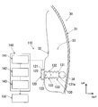
- FIG. 2 shows a longitudinal sectional structure of the vehicle door 30 to which the pressure sensor 120 in FIG. 1 is attached
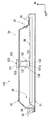
- FIG. 3 shows a transverse sectional structure of the vehicle door 30 in FIG. ing. 4 shows the operation of the cylindrical member 130 at the time of a side collision of the vehicle 10 in the longitudinal sectional structure of the vehicle door 30 in FIG.
- the arrow “UP” is the upper side of the vehicle
- the arrow “FR” is the front side of the vehicle (forward travel direction)
- the arrow “IN” is the inside of the vehicle (vehicle compartment side)
- the arrow “OUT” is the outside of the vehicle ( The outdoor side) is shown respectively.
- the vehicle door 30 of the vehicle 10 is connected to the vehicle main body 37 via a door hinge 36.
- the vehicle door 30 includes a door outer panel 31 that forms an outer wall of the vehicle, and a door inner panel 32 that forms an inner wall of the vehicle.
- the vehicle door 30 may be a front seat door installed between the A pillar and the B pillar of the vehicle 10, or may be a rear seat door installed between the B pillar and the C pillar.
- a metal door beam 38 as a door reinforcing member is disposed in a partition region 33 partitioned by the door outer panel 31 and the door inner panel 32.
- the vehicle door 30, the door outer panel 31, the door inner panel 32, and the partition area 33 referred to here correspond to “vehicle door”, “door outer panel”, “door inner panel”, and “partition area” in the present invention, respectively. .
- the door beam 38 is a cylindrical, rod-like or columnar member extending in a longitudinal shape in the vehicle front-rear direction.
- One end of the door beam 38 is fixed to the vehicle body 37 via the vehicle front side bracket 34, while the other end is the vehicle rear side. It is fixed to the vehicle body 37 via the side bracket 35. That is, the door beam 38 has both ends corresponding to the brackets 34 and 35 as fixed ends, and is between the door front end (vehicle front side bracket 34) and the door rear end (vehicle rear side bracket 35) in the vehicle longitudinal direction. It is erected in a long shape.
- the door beam 38 functions as a displacement member that absorbs an impact by being displaced flexibly with the deformation of the door outer panel 31 during a side collision of the vehicle 10.
- the door beam 38 here corresponds to the “displacement member” in the present invention.
- the door beam 38 is also referred to as “a reinforcing member for reinforcing the vehicle door 30” or “an erection member erected in the vehicle longitudinal direction of the vehicle door 30”.
- a cylindrical member 130 is disposed in a partition region 33 between the door outer panel 31 and the door inner panel 32 so as to be connected to the door beam 38.
- the cylindrical member 130 may be connected in contact with the door beam 38, or the cylindrical member 130 may be connected to the door beam 38 with a predetermined gap or space therebetween.
- the tubular member 130 is a member that is compressed by the door beam 38 that is displaced in the event of a side collision of the vehicle 10.
- the cylindrical member 130 is a bottomed cylindrical member having a cylindrical wall 131 that forms a sealed space portion 133 with the pressure sensor 120, and includes the door inner panel 32 and the door beam 38. Extending between.
- the cylindrical member 130 is made of a material such as a metal material or a resin material as necessary.
- a bellows-like fold portion 132 is provided on the cylindrical wall 131 of the cylindrical member 130.
- the folding part 132 functions as a part that allows the tubular member 130 to extend and contract in the left-right direction (reducing operation in the vehicle interior and extending operation in the vehicle exterior direction).
- the folding portion 132 is reduced in volume with respect to the vehicle interior direction in which the space portion 133 is defined in particular when the bottom portion of the cylindrical member 130, that is, when the distal end portion 131 a facing the door outer panel 31 is compressed by the door beam 38. At least the function of guiding the cylindrical member 130 is achieved.
- the door inner panel 32 is deformed from the initial state indicated by the two-dot chain line to the deformation position indicated by the solid line, and together with the door inner panel 32.
- the cylindrical member 130 is compressed by the door beam 38 that bends in the in-vehicle direction (left side in FIG. 4).
- the tubular member 130 is reduced in the in-vehicle direction via the fold portion 132 so that the volume of the space 133 is crushed in the in-vehicle direction and reduced in volume.
- the cylindrical member 130 here corresponds to the “compressed member” and the “cylindrical member” in the present invention, and the cylindrical wall 131, the folding fold portion 132, and the space portion 133 of the cylindrical member 130 are the present invention, respectively.
- the pressure sensor 120 is a diaphragm type pressure sensor, and houses a sensor element including a thin diaphragm portion 122 in the sensor housing 121.
- the pressure sensor 120 detects a pressure change based on a change in resistance value caused by distortion when pressure acts in the thickness direction of the diaphragm portion 122.
- pressure acts in the thickness direction of the diaphragm portion 122 through the communication portion 123 that communicates between the space portion 133 of the tubular member 130 and the pressure sensor 120.
- the pressure sensor 120 detects a pressure fluctuation when the volume of the space portion 133 of the tubular member 130 is reduced during the side collision of the vehicle 10.
- the pressure sensor 120 is attached to the door inner panel 32, the door outer panel 31, the door beam 38, etc. directly or indirectly via a bracket.
- the pressure sensor 120 here corresponds to the “pressure sensor” in the present invention.
- the detection signal detected by the pressure sensor 120 is transmitted to the ECU 140 and appropriately processed.
- the ECU 140 includes a CPU (arithmetic processing unit), an input / output device, a storage device, a drive device, a peripheral device, and the like, and includes at least a derivation unit 141, a determination unit 142, and a drive control unit 143 as shown in FIG. ing.
- the deriving unit 141 performs a function of deriving a displacement amount and a displacement speed of the door beam 38 at the time of a side collision of the vehicle 10 based on the pressure fluctuation detected by the pressure sensor 120.
- the deriving unit 141 here corresponds to a “derivation unit” in the present invention.
- the derivation unit 141 typically stores in advance a database in which data relating to pressure fluctuation is associated with data relating to the displacement amount and displacement speed of the door beam 38.
- the deriving unit 141 derives the actual displacement amount and the displacement speed of the door beam 38 by reading the displacement amount and the displacement speed corresponding to the actually detected pressure fluctuation from this database.
- the determination unit 142 has a function of determining the collision mode of the vehicle 10 based on the displacement amount and the displacement speed of the door beam 38 derived by the deriving unit 141.
- the determination unit 142 here corresponds to a “determination unit” in the present invention.
- the determination unit 142 should drive the airbag module 150 when a collision of the vehicle 10 has occurred or the relationship between the displacement amount and the displacement speed of the door beam 38 is within a predetermined range. Judged as a collision.
- the determination unit 142 does not cause a collision of the vehicle 10 or causes a collision to drive the airbag module 150. It is determined that it is not.
- the drive control unit 143 outputs a drive control signal to the airbag module 150 when the determination unit 142 determines that a collision of the vehicle 10 has occurred or that the airbag module 150 should be driven. .
- the airbag of the airbag module 150 is deployed and inflated in the restraining region of the vehicle occupant, and the vehicle occupant can be restrained.
- the drive control unit 143 here corresponds to the “drive control unit” in the present invention.
- the occupant restraint device controlled by the drive control signal from the drive control unit 143 of the ECU 140 is replaced with or in addition to the airbag module 150.
- An apparatus can be used.
- the occupant restraint device other than the airbag module 150 include an occupant restraint device such as a seat belt device, and a notification device that performs display output and audio output to perform notification of a side collision.
- the sealing property of the division area 33 is implement
- the pressure sensor 120 is used for detection.
- the pressure in the space portion 133 fluctuates appropriately in response to the displacement of the door outer panel 31 at the time of the vehicle collision, and the collision mode of the vehicle 10 can be accurately detected using the pressure sensor 120.
- the time change rate of the pressure is small, so the pressure fluctuation is detected.
- the use of the sealed space portion 133 can reduce the sensitivity of the pressure sensor, and even in the case of a pole collision. Sensitivity deterioration due to the pressure sensor is prevented. Such operational effects will be further described in detail with reference to FIG.
- Example A when the vehicle collision detection device 110 of the present embodiment is used, that is, when the pressure of the space portion 133 of the tubular member 130 as the pressure detection region is detected (Example A), and as the pressure detection region For each of the cases where the pressure in the compartment region 33 of the vehicle door 30 is detected (Comparative Example B), an overview of the time change in pressure in the pressure detection region (vertical axis: pressure P, horizontal axis: time t) is shown. Has been. Further, in FIG. 5, a curve A1 shows a state at the time of high-speed collision in which the collision speed of the collision object is relatively high in Example A, and a curve A2 is about half the speed in Example A at the time of high-speed collision.
- Curve B1 shows the state at the time of high-speed collision in which the collision speed of the collision target is relatively high in Comparative Example B
- curve B2 shows the time of low-speed collision at about half the speed of high-speed collision in Comparative Example B. Shows the state.
- Example A since the pressure detection area is highly sealed, it is possible to suppress a decrease in pressure sensitivity even when the rate of time change in pressure is small, particularly during low-speed collisions. It is understood that
- the deformation direction when the cylindrical member 130 is deformed is always the same direction. Since the configuration is such that directionality is imparted, stable pressure detection by the pressure sensor 120 is possible. Further, since the cylindrical member 130 is compressed and deformed by the door beam 38 extending over a wide range in the front-rear direction of the vehicle door 30, the door outer panel can be applied to any part of the vehicle door 30 that collides with the collision object. The deformation of 31 can be reliably transmitted to the tubular member 130 via the door beam 38.
- vehicle collision detection devices 210, 310, 410, and 510 according to another embodiment of the “vehicle collision detection device” of the present invention will be described with reference to FIGS. 6 to 9, the same components as those in FIG. 2 are denoted by the same reference numerals, and the description of the same components is omitted.
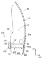
- the door outer panel 31 is employed as a displacement member that compresses the tubular member 230. That is, the cylindrical member 230 is not compressed by the door beam 38 but functions as a member to be compressed that is directly compressed by the door outer panel 31. Specifically, at the time of a side collision of the vehicle 10, the distal end portion 131 a of the cylindrical member 230 is compressed by the inner wall surface 31 a of the door outer panel 31, that is, the wall surface facing the door inner panel 32.
- an attachment member 39 attached to the door beam 38 is employed as a displacement member that compresses the cylindrical member 330. That is, the tubular member 330 is not directly compressed by the door outer panel 31 or the door beam 38 but functions as a member to be compressed that is indirectly compressed by the door beam 38 via the attachment member 39. Specifically, at the time of a side collision of the vehicle 10, the distal end portion 131 a of the cylindrical member 330 is compressed by the wall surface of the mounting member 39 that faces the door inner panel 32.
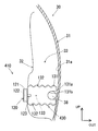
- the vehicle collision detection device 410 employs both the door beam 38 and the door outer panel 31 as displacement members that compress the cylindrical member 430. That is, the cylindrical member 430 functions as a member to be compressed that is directly compressed by the door beam 38 and the door outer panel 31. Specifically, at the time of a side collision of the vehicle 10, the tip 131 a of the cylindrical member 430 is compressed by the inner wall surface 31 a of the door outer panel 31, that is, the wall surface facing the door inner panel 32, and the cylindrical member 430. A recess 131 b formed on the front end side of the door is compressed by the door beam 38.
- a vehicle collision detection device 510 is a further modification of the vehicle collision detection device 410.
- the pressure sensor 120 is disposed at a position separated from the door inner panel 32, and the communication portion 123 of the pressure sensor 120 is connected to the space portion 133 of the tubular member 430 through the pressure derivation tube 124.
- a configuration that allows direct communication is adopted.
- the collision mode of the vehicle 10 can be accurately detected using the pressure sensor 120 as in the case of using the vehicle collision detection device 110. Is possible.
- the cylindrical member 130 is used as a member to be compressed that is compressed by a displacement member such as the door beam 38 or the door outer panel 31 .
- the door outer panel 31 and the door inner panel 32 are used.
- Other members other than the cylindrical member 130 can be used as long as it is possible to form a sealed space portion in the partition region 33 partitioned by.
- a piston member that is compressed by the displacement member and a cylinder member that guides the movement of the piston member and forms a sealed space between the piston member and the piston member may be used.
- the tubular members 130, 230, 330, and 430 move a small amount of air between the partition region 33 and the space portion 133 to absorb the influence of atmospheric pressure and thermal expansion (
- a small-diameter opening hole that allows leakage) can be provided.
- the opening hole has a diameter that does not impair the desired sealing property of the space portion 133. Air leakage can be controlled through the opening.
- the sealed space portion 133 of the cylindrical members 130, 230, 330, and 430 in each embodiment may be a completely sealed space portion that does not allow any air in the space portion 133 to leak into the partition region 33.
- it may be a space portion that allows a small amount of air in the space portion 133 to leak into the partition region 33 in order to absorb the influence of atmospheric pressure or thermal expansion.
- the airbag module 150 that restrains the vehicle occupant using the airbag as the occupant restraint device is employed, but in the present invention, instead of or in addition to the airbag module 150, An occupant restraint device such as a seat belt device that restrains the chest and abdomen of an occupant seated on a vehicle seat via a seat belt can be used.
- An occupant restraint device such as a seat belt device that restrains the chest and abdomen of an occupant seated on a vehicle seat via a seat belt can be used.
- the configuration of the occupant restraint system to be mounted on the automobile has been described.
- the present invention is applied to the configuration of the occupant restraint system to be mounted on various vehicles such as cars, trains, buses, and trucks. Can be applied.
Landscapes
- Engineering & Computer Science (AREA)
- Mechanical Engineering (AREA)
- Air Bags (AREA)
Abstract
【課題】車両の衝突態様を圧力センサを用いて精度よく検出するのに有効な技術を提供する。 【解決手段】車両に搭載される乗員拘束システム100は、車両ドア30のドアアウタパネル31とドアインナパネル32とで区画される区画領域33に配設され、車両衝突時のドアアウタパネル31の変形に伴って変位するドアビーム38と、区画領域33に配設され、ドアビーム38の変位の際にドアビーム38によって圧縮される筒状部材130と、筒状部材130に設けられた密閉状の空間部133と、空間部133の圧力変動を検出する圧力センサ120と、圧力センサ120によって検出された圧力変動に基づいて、ドアビーム38の変位量及び変位速度を導出する導出部141と、導出部141において導出されたドアビーム38の変位量及び変位速度に基づいて車両の衝突態様を判定する判定部142と、を有する。
Description
本発明は、車両衝突を検出する技術に関するものである。
従来、車両事故の際の衝突発生を検出する種々の車両衝突センサが知られている。例えば、下記特許文献1には、圧力センサを用いて車両の衝突態様を検出する技術が開示されている。引用文献1に開示されたこの圧力センサは、車両ドアのドアアウタパネルとドアインナパネルとの間に形成されるドア内空間に配設され、このドア内空間の圧力変化を検出する。ドアアウタパネルとドアインナパネルとによって区画されるドア内空間の密閉性を高いレベルで実現するのは難しいため、ドア内空間の圧力変動と車両の衝突態様とを適正に関連付けるのには限界がある。とりわけ、車両がポール状の衝突対象物に衝突したポール衝突のように、衝突速度が小さくても車両変形量が大きい衝突事象にあっては、圧力の時間変化率が小さくなるため、ドア内空間の密閉性が低いと圧力センサによる検出精度が相当に低下するという問題が生じる。
そこで、本発明は、かかる点に鑑みてなされたものであり、車両の衝突態様を圧力センサを用いて精度よく検出するのに有効な技術を提供することを課題とする。
前記課題を解決するために、本発明が適用される。本発明は、典型的には自動車において発生した側面衝突に関する情報を判定する技術に対し適用することができるが、自動車以外の車両において発生した側面衝突に関する情報を検出する技術に対しても同様に、本発明を適用することが可能である。ここでいう「車両」には、自動車、電車、バス、トラック等の各種の車両が包含される。
本発明にかかる車両衝突検出装置は、車両に搭載される装置であって、変位部材、被圧縮部材、空間部、圧力センサ、導出部及び判定部を含む。これら各構成要素のうち、導出部及び判定部は、それぞれ個別の処理要素としてもよいし、或いは単一の処理要素としてもよい。
変位部材は、車両ドアのドアアウタパネルとドアインナパネルとで区画される区画領域に配設され、車両衝突時のドアアウタパネルの変形に伴って変位する部材である。この変位部材としては、ドアアウタパネルとドアインナパネルとで区画される区画領域に配設される各種の部材を用いることができ、典型的には車両ドアを補強するべく区画領域に配設された補強部材やドアアウタパネルの内壁部をはじめ、これら補強部材やドアアウタパネルに取付けられた取付け部材のうちの少なくとも1つを採用することが可能である。特に、車両前後方向に広範囲にわたり長尺状に延在する補強部材を用いる場合には、衝突対象物が車両ドアのどの部位に衝突しても、ドアアウタパネルの変形を変位部材に確実に伝えるのに有効である。
被圧縮部材は、ドアアウタパネルとドアインナパネルとで区画される区画領域に配設され、変位部材の変位の際に当該変位部材によって圧縮される。この被圧縮部材は、典型的には区画領域において変位部材に連接して配設される。ここでいう「連接」には、被圧縮部材が変位部材に対し当接状に連接する態様や、隙間を隔てて連接する態様等が包含される。空間部は、この被圧縮部材に設けられた密閉状の空間部である。この空間部の圧力変動、特には空間部が減容化したときの圧力変動が圧力センサによって検出される。なお、ここでいう「密閉状の空間部」は、空間部の空気が区画領域に漏れるのを一切許容しない完全密封された空間部分としてもよいし、或いは大気圧や熱膨張による影響を吸収するべく空間部の微量の空気が区画領域に漏れるのを許容する空間部分としててもよい。空間部の微量の空気が区画領域に漏れるのを許容する構成の場合には、空間部と区画領域とを連通する小径の開口孔、すなわち空間部の所望の密閉性を損なわない程度の径に設定された開口孔を用い、この開口孔を通じて空気の漏れをコントロール可能とするのが好ましい。
導出部は、圧力センサによって検出された圧力変動に基づいて、変位部材の変位量及び変位速度を導出する機能を有する。導出部は、典型的には、圧力変動に関するデータと、変位部材の変位量及び変位速度に関するデータとを関連付けるデータベースを予め記憶しておき、実際に検出した圧力変動に対応した変位量及び変位速度をこのデータベースから読み出すことによって、変位部材の実際の変位量及び変位速度を導出する。判定部は、導出部において導出された変位部材の変位量及び変位速度に基づいて車両の衝突態様を判定する機能を有する。この判定部は、典型的には変位部材の変位量と変位速度との関係が予め規定された所定範囲にある場合に、車両の衝突が発生した、若しくは作動装置を駆動するべき衝突であると判定する。一方、判定部は、変位部材の変位量と変位速度との関係が前記の所定範囲を外れている場合に、車両の衝突は発生していない、若しくは作動装置を駆動するべき衝突ではないと判定する。ここでいう「作動装置」としては、エアバッグないしシートベルトを介して車両乗員を拘束するための装置、車両の衝突に関する情報を出力する装置などを用いることができる。
本発明にかかる車両衝突検出装置では、上記構成のように、車両ドアのドアアウタパネルとドアインナパネルとによって区画される区画領域において、更に被圧縮部材に密閉状の空間部を設け、この空間部の圧力変動を圧力センサによって検出するようにしている。これにより、車両衝突時のドアアウタパネルの変位に適正に対応して空間部の圧力が変動することとなり、車両の衝突態様を圧力センサを用いて精度よく検出することが可能となる。特に、車両がポール状の衝突対象物に衝突した場合のように、衝突速度が小さくても車両変形量が大きい衝突事象にあっては、圧力の時間変化率が小さくなるため、圧力変動を検出する空間の密閉性が低いと圧力センサによる感度が相当に低下するという問題が生じる。これに対し、本発明にかかる車両衝突検出装置では、密閉状の空間部の圧力変動を検出することで、ポール衝突のような場合であっても圧力センサによる感度低下が防止される。
本発明にかかる更なる形態の車両衝突検出装置は、更にガイド機構を備える構成であるのが好ましい。このガイド機構は、被圧縮部材が変位部材によって圧縮されたとき、空間部が予め規定された所定方向に潰れて減容化されるように被圧縮部材をガイドする機構である。このような構成によれば、被圧縮部材が圧縮されて空間部が潰れる方向が常に同一の方向となるようにガイド機構によって方向性が付与されるため、圧力センサによる安定した圧力検出が可能となる。なお、本構成に関しては、筒壁によって空間部を形成する筒状部材を被圧縮部材として用い、この筒状部材の筒壁に設けた蛇腹状の折り襞部をガイド機構として用いる構成や、変位部材によって圧縮されるピストン部材を被圧縮部材として用い、このピストン部材の移動をガイドするとともにピストン部材との間で空間部を形成するシリンダ部材をガイド機構として用いる構成等を採用することが可能である。
本発明にかかる更なる形態の車両衝突検出装置では、前記の被圧縮部材は、ドアインナパネルと変位部材との間に延在する筒壁によって空間部を形成する筒状部材とするのが好ましい。また、前記のガイド機構は、筒状部材の筒壁に設けられた蛇腹状の折り襞部であり、空間部が筒壁の延在方向に潰れて減容化されるように折り襞部を介して筒状部材をガイドするのが好ましい。本構成の場合、筒状部材の筒壁自体の剛性によって筒壁と交差する方向に関する空間部の潰れが規制される一方、筒壁に設けた蛇腹状の折り襞部によって筒壁の延在方向に関する空間部の潰れが許容されて当該空間部が容易に減容化される。このような構成によれば、筒状部材の筒壁に蛇腹状の折り襞部を設けることによって、被圧縮部材とガイド機構とを単一部品によって構成した簡便な構造を実現することが可能となる。
本発明にかかる乗員拘束システムは、前記の各車両衝突検出装置と、車両乗員を拘束する乗員拘束装置と、車両の側面衝突の際、車両衝突検出装置の判定部における判定結果に基づいて乗員拘束装置を駆動制御する駆動制御部とを少なくとも備える。ここでいう「乗員拘束装置」として典型的には、乗員拘束領域に展開膨張するエアバッグによって乗員拘束を図るエアバッグ装置(エアバッグモジュール)や、車両シートに着座した乗員の胸部や腹部をシートベルトを介して拘束するシートベルト装置などの乗員拘束デバイスが包含される。この場合、乗員拘束装置としてエアバッグ装置を用いる場合には、エアバッグがシート、ピラー、上部ルーフレールなどに収容される形態のエアバッグ装置を採用することができる。また、乗員拘束装置を駆動制御する駆動制御部は、乗員拘束装置に専用の制御を行なう制御部としてもよいし、或いは乗員拘束装置の制御に加えて、当該乗員拘束装置以外の更なる制御対象(例えば車両のエンジン走行系統や電装系統)の制御を兼務する制御部としてもよい。このような構成によれば、前記の各車両衝突検出装置の圧力センサを用いて精度よく検出された車両の衝突態様の判定結果に基づいて乗員拘束装置を制御することが可能な乗員拘束システムが提供される。
本発明にかかる車両は、エンジン走行系統、電装系統、制御装置、車両ドア、衝突判定装置、乗員拘束装置及び駆動制御部を含む。エンジン走行系統は、エンジン及び車両の走行に関与する系統として機能する。電装系統は、車両に使われる電機部品に関与する系統として機能する。制御装置は、エンジン走行系統及び電装系統の駆動制御を行う機能を有する装置として機能する。車両ドアは、側面衝突によりドアアウタパネルが変位する乗員乗降用のドアとして機能する。衝突判定装置は、車両ドアの側面衝突態様を判定する装置として機能する。この衝突判定装置が、前記の各車両衝突検出装置によって構成される。乗員拘束装置は、前述の乗員拘束装置と同様に、車両乗員を拘束する乗員拘束装置として機能する。駆動制御部は、前述の制御部と同様に、車両の側面衝突の際、衝突判定装置における判定結果に基づいて乗員拘束装置を駆動制御する機能を果たす。このような構成によれば、前記の各車両衝突検出装置の圧力センサを用いて精度よく検出された車両の衝突態様の判定結果に基づいて制御される乗員拘束装置を備えた車両が提供される。
本発明によれば、車両の衝突態様を圧力センサを用いて精度よく検出することができる。
以下、図1~図5を参照しながら本発明における「乗員拘束システム」の一実施の形態である乗員拘束システム100について説明する。本実施の形態では、乗員拘束を行う乗員拘束装置として、事故発生の際に乗員拘束領域へのエアバッグの展開膨張が可能なエアバッグモジュールを採用している。このエアバッグモジュールは、運転席、助手席、後部座席等に対応して設置される。
本実施の形態の乗員拘束システム100が、車両乗員が乗車する車両10に搭載された様子が図1に模式的に示される。本発明における「車両」としての車両10は、特に図示しないものの、当該車両を構成する多数の車両構成部材、エンジン及び車両の走行に関与する系統であるエンジン走行系統、車両に使われる電機部品に関与する系統である電装系統、エンジン走行系統及び電装系統の駆動制御を行う駆動制御手段等を備えている。
この乗員拘束システム100は、車両10の側面衝突事故の際、当該側面衝突に関する情報に基づいて、車両乗員を速やかに拘束する制御を行なうシステムである。図1に示すように、この乗員拘束システム100は、車両衝突検出装置110、ECU140及びエアバッグモジュール150を少なくとも備える。
車両衝突検出装置110は、詳細については後述するが、車両ドア30に装着される圧力センサ120を有しており、車両10の衝突態様に関与する圧力情報を、圧力センサ120を介して検出する装置として機能する。ここでいう車両衝突検出装置110が本発明における「車両衝突検出装置」に相当する。
ECU140は、圧力センサ120を介して検出された圧力情報に基づいて、エアバッグモジュール150に対し駆動制御信号を出力する機能を有する。このECU140は、車両のエンジン走行系統や電装系統の制御を行なう制御装置(本発明における「制御装置」に相当する)としての制御ユニットの一部としてもよい。
エアバッグモジュール150は、特に図示しないものの、エアバッグ及びガス供給装置を少なくとも備える。当該エアバッグは、典型的には布地によって袋状に形成され、膨張及び収縮が可能な部材である。このエアバッグは、ECU150から出力された駆動制御信号に基づいてガス供給装置が作動したとき、当該ガス供給装置からのガス供給によって乗員拘束領域に展開膨張する。これにより、車両事故の際、エアバッグモジュール150のエアバッグが車両乗員を拘束することが可能となる。このエアバッグモジュール150は、乗員拘束用のエアバッグがシート、ピラー、上部ルーフレールなどに適宜収容される形態のエアバッグ装置である。ここでいうエアバッグモジュール150は、車両の側面衝突の際、車両乗員を拘束する装置として機能し、本発明における「乗員拘束装置」に相当する。
次に、上記の車両衝突検出装置110及びECU140の更なる詳細について、図2及び図3を参照しつつ説明する。ここで、図2には、図1中の圧力センサ120が取り付けられた車両ドア30の縦断面構造が示され、また図3には、図2中の車両ドア30の横断面構造が示されている。また、図4には、図2中の車両ドア30の縦断面構造において、車両10の側面衝突の際の筒状部材130の動作が示されている。なお、これらの図において矢印「UP」が車両上方、矢印「FR」が車両前方(前進走行方向)、矢印「IN」が車両内方(車室側)、矢印「OUT」が車両外方(室外側)をそれぞれ示している。
図2及び図3に示すように、車両10の車両ドア30は、ドアヒンジ36を介して車両本体37に連結されている。この車両ドア30は、車両の外側壁を形成するドアアウタパネル31、車両の内側壁を形成するドアインナパネル32を備える。この車両ドア30は、車両10のAピラーとBピラーとの間に設置される前席ドアとしてもよいし、或いはBピラーとCピラーとの間に設置される後席ドアとしてもよい。これらドアアウタパネル31及びドアインナパネル32によって区画される区画領域33には、ドア補強部材としての金属製のドアビーム38が配設されている。ここでいう車両ドア30、ドアアウタパネル31、ドアインナパネル32及び区画領域33が、それぞれ本発明における「車両ドア」、「ドアアウタパネル」、「ドアインナパネル」及び「区画領域」に対応している。
ドアビーム38は、車両前後方向にわたり長尺状に延在する筒状、棒状ないし柱状の部材であり、一端が車両前方側ブラケット34を介して車両本体37に固定される一方、他端が車両後方側ブラケット35を介して車両本体37に固定される。すなわち、このドアビーム38は、ブラケット34,35に対応する両端を固定端として、車両前後方向に関しドア前端部(車両前方側ブラケット34)とドア後端部(車両後方側ブラケット35)との間に長尺状に架設されている。このドアビーム38は、車両10の側面衝突の際、ドアアウタパネル31の変形に伴って撓み状に変位することによって衝撃を吸収する変位部材として機能する。ここでいうドアビーム38が、本発明における「変位部材」に相当する。またこのドアビーム38は、「車両ドア30の補強のための補強部材」或いは「車両ドア30の車両前後方向に架設された架設部材」とも称呼される。
また、ドアアウタパネル31とドアインナパネル32との間の区画領域33には、このドアビーム38に連接して筒状部材130が配設されている。ここで、筒状部材130がドアビーム38に対し当接状に連接してもよいし、或いは筒状部材130がドアビーム38に対し所定の隙間ないし空間を隔てて連接してもよい。この筒状部材130は、車両10の側面衝突の際に変位するドアビーム38によって圧縮される部材である。具体的には、この筒状部材130は、圧力センサ120との間で密閉状の空間部133を形成する筒壁131を有する有底の筒状の部材であり、ドアインナパネル32とドアビーム38との間に延在する。この筒状部材130は、必要に応じて金属材料や樹脂材料などの素材によって構成される。
また、この筒状部材130の筒壁131には、蛇腹状の折り襞部132が設けられている。この折り襞部132は、筒状部材130の左右方向への伸縮動作(車内方向への縮小動作と車外方向への延伸動作)を許容する部位として機能する。この折り襞部132は、特には筒状部材130の底部、すなわちドアアウタパネル31に対向する先端部131aがドアビーム38によって圧縮されたとき、空間部133が予め規定された車内方向に関し減容化されるように筒状部材130をガイドする機能を少なくとも果たす。
図4に示すように、衝突対象物Pに対する車両10の側面衝突の際には、ドアインナパネル32が二点鎖線で示す初期状態から実線で示す変形位置へと変形し、ドアインナパネル32とともに車内方向(図4中の左側)へと撓み動作するドアビーム38によって筒状部材130が圧縮される。そして、この圧縮により、筒状部材130は、空間部133が車内方向に潰れて減容化されるように、折り襞部132を介して車内方向へと縮小動作する。このとき空間部133は、筒状部材130の筒壁131自体の剛性によって筒壁131と交差する方向に関する潰れが規制される一方、筒壁131に設けた蛇腹状の折り襞部132によって筒壁131に沿った方向へと潰れが許容されて、容易に減容化される。ここでいう筒状部材130が、本発明における「被圧縮部材」及び「筒状部材」に相当し、この筒状部材130の筒壁131、折り襞部132及び空間部133がそれぞれ、本発明における「筒壁」、「折り襞部(ガイド機構)」及び「空間部」に相当する。
圧力センサ120は、ダイアフラム型の圧力センサであり、薄肉状のダイアフラム部122を備えたセンサ素子をセンサハウジング121内に収容する。この圧力センサ120は、ダイアフラム部122の厚み方向に圧力が作用したときの歪みによって生じる抵抗値の変化に基づいて圧力変化を検出する。本実施の形態では、筒状部材130の空間部133と圧力センサ120との間を連通する連通部123を通じて、ダイアフラム部122の厚み方向に圧力が作用する。これにより、車両10の側面衝突の際に筒状部材130の空間部133が減容化されたときの圧力変動が圧力センサ120によって検出される。この圧力センサ120は、ドアインナパネル32、ドアアウタパネル31、ドアビーム38等に対して、直接的に或いはブラケットを介して間接的に取付けられる。ここでいう圧力センサ120が、本発明における「圧力センサ」に相当する。
前記の圧力センサ120によって検出された検出信号は、ECU140に伝送されて適宜に信号処理される。ECU140は、CPU(演算処理装置)、入出力装置、記憶装置、駆動装置、周辺装置等によって構成され、図2に示すように、少なくとも導出部141、判定部142及び駆動制御部143を有している。
導出部141は、圧力センサ120によって検出された圧力変動に基づいて、車両10の側面衝突の際のドアビーム38の変位量及び変位速度を導出する機能を果たす。ここでいう導出部141が、本発明における「導出部」に相当する。この導出部141は、典型的には、圧力変動に関するデータと、ドアビーム38の変位量及び変位速度に関するデータとを関連付けたデータベースを予め記憶している。そして導出部141は、実際に検出した圧力変動に対応した変位量及び変位速度をこのデータベースから読み出すことによって、ドアビーム38の実際の変位量及び変位速度を導出する。
判定部142は、導出部141において導出されたドアビーム38の変位量及び変位速度に基づいて車両10の衝突態様を判定する機能を果たす。ここでいう判定部142が、本発明における「判定部」に相当する。この判定部142は、典型的にはドアビーム38の変位量と変位速度との関係が予め規定された所定範囲にある場合に、車両10の衝突が発生した、若しくはエアバッグモジュール150を駆動するべき衝突であると判定する。一方、判定部142は、ドアビーム38の変位量と変位速度との関係が前記の所定範囲を外れている場合に、車両10の衝突は発生していない、若しくはエアバッグモジュール150を駆動するべき衝突ではないと判定する。
そして、駆動制御部143は、車両10の衝突が発生した、若しくはエアバッグモジュール150を駆動するべき衝突であると判定部142が判定した場合に、エアバッグモジュール150に対し駆動制御信号を出力する。これにより、エアバッグモジュール150のエアバッグが、車両乗員の拘束領域に展開膨張して、当該車両乗員を拘束することが可能となる。ここでいう駆動制御部143が、本発明における「駆動制御部」に相当する。
なお、この乗員拘束システム100において、ECU140の駆動制御部143からの駆動制御信号によって制御される乗員拘束装置は、エアバッグモジュール150に代えて或いは加えて、エアバッグモジュール150とは別の乗員拘束装置を用いることが可能である。エアバッグモジュール150とは別の乗員拘束装置としては、シートベルト装置などの乗員拘束装置や、側面衝突の報知などを行うべく表示出力や音声出力を行う報知装置などが挙げられる。
ところで、車両ドア30のドアアウタパネル31とドアインナパネル32とによって区画される区画領域33の圧力変動を圧力センサ120によって直接的に検出する構成では、区画領域33の密閉性を高いレベルで実現するのは難しいことから、車両の衝突態様を精度よく検出するのには限界がある。そこで、本実施の形態の車両衝突検出装置110では、ドアアウタパネル31とドアインナパネル32とによって区画される区画領域33に更に、密閉状の空間部133を設け、この空間部133の圧力変動を圧力センサ120によって検出する構成とする。
これにより、車両衝突時のドアアウタパネル31の変位に適正に対応して空間部133の圧力が変動することとなり、車両10の衝突態様を圧力センサ120を用いて精度よく検出することが可能となる。特に、車両がポール状の衝突対象物に衝突した場合のように、衝突速度が小さくても車両変形量が大きい衝突事象にあっては、圧力の時間変化率が小さくなるため、圧力変動を検出する空間の密閉性が低いと圧力センサによる感度が相当に低下するという問題が生じるが、本実施の形態では、密閉状の空間部133を用いることで、ポール衝突のような場合であっても圧力センサによる感度低下が防止される。このような作用効果について、更に図5を用いて詳細に説明する。
図5には、本実施の形態の車両衝突検出装置110を用いる場合、すなわち圧力検出領域としての筒状部材130の空間部133の圧力を検出する場合(実施例A)と、圧力検出領域としての車両ドア30の区画領域33の圧力を検出する場合(比較例B)のそれぞれに関し、当該圧力検出領域での圧力の時間変化(縦軸:圧力P、横軸:時間t)の概要が示されている。また、図5中において、曲線A1は、実施例Aにおいて衝突対象物の衝突速度が相対的に高い高速衝突時の状態を示し、曲線A2は、実施例Aにおいて高速衝突時の半分程度の速度での低速衝突時の状態を示す。また、曲線B1は、比較例Bにおいて衝突対象物の衝突速度が相対的に高い高速衝突時の状態を示し、曲線B2は、比較例Bにおいて高速衝突時の半分程度の速度での低速衝突時の状態を示す。
図5に示すように、比較例Bでは、実施例Aに比べて圧力検出領域の密閉性が低いことから、特に低速衝突時のように圧力の時間変化率が小さい場合には、圧力の感度が低下することが理解される。これに対して、実施例Aでは、圧力検出領域の密閉性が高いことから、特に低速衝突時のように圧力の時間変化率が小さい場合であっても、圧力の感度低下を抑えることが可能であることが理解される。
また、上記構成の車両衝突検出装置110では、筒状部材130の筒壁131に蛇腹状の折り襞部132を設けることによって、筒状部材130が変形する際の変形方向が常に同一の方向となるように方向性を付与する構成としたため、圧力センサ120による安定した圧力検出が可能となる。更に、車両ドア30の前後方向にわたって広範囲に延在するドアビーム38によって筒状部材130が圧縮されて変形するように構成したため、衝突対象物が車両ドア30のどの部位に衝突しても、ドアアウタパネル31の変形を、ドアビーム38を介して筒状部材130に確実に伝えることが可能となる。
なお、筒状部材130の構成や圧力センサ120の配置等に関しては、図2等に示す上記構成の車両衝突検出装置110に限定されるものではなく、設計仕様等、必要に応じて適宜に変更可能である。以下、図6~図9を参照しつつ、本発明の「車両衝突検出装置」にかかる別実施の形態の車両衝突検出装置210,310,410,510について説明する。なお、これら図6~図9において、図2中の構成要素と同一の構成要素には同一の符号を付しており、当該同一の構成要素についての説明は省略する。
図6に示す別実施の形態の車両衝突検出装置210では、筒状部材230を圧縮する変位部材としてドアアウタパネル31を採用している。すなわち、この筒状部材230は、ドアビーム38によって圧縮されるものではなく、ドアアウタパネル31によって直接的に圧縮される被圧縮部材として機能する。具体的には、車両10の側面衝突の際、筒状部材230の先端部131aが、ドアアウタパネル31の内壁面31a、すなわちドアインナパネル32に対向する壁面によって圧縮される。
また、図7に示す別実施の形態の車両衝突検出装置310では、筒状部材330を圧縮する変位部材としてドアビーム38に取付けられた取付け部材39を採用している。すなわち、この筒状部材330は、ドアアウタパネル31やドアビーム38によって直接的に圧縮されるものではなく、取付け部材39を介してドアビーム38によって間接的に圧縮される被圧縮部材として機能する。具体的には、車両10の側面衝突の際、筒状部材330の先端部131aが、取付け部材39のうちドアインナパネル32に対向する壁面によって圧縮される。
また、図8に示す別実施の形態の車両衝突検出装置410は、筒状部材430を圧縮する変位部材としてドアビーム38及びドアアウタパネル31の双方を採用している。すなわち、この筒状部材430は、ドアビーム38及びドアアウタパネル31によって直接的に圧縮される被圧縮部材として機能する。具体的には、車両10の側面衝突の際、筒状部材430の先端部131aが、ドアアウタパネル31の内壁面31a、すなわちドアインナパネル32に対向する壁面によって圧縮されるとともに、筒状部材430の先端側に形成された凹部131bが、ドアビーム38によって圧縮される。
また、図9に示す別実施の形態の車両衝突検出装置510は、車両衝突検出装置410の更なる変更例である。この車両衝突検出装置510では、圧力センサ120をドアインナパネル32から離間した位置に配設するとともに、この圧力センサ120の連通部123を、圧力導出管124を通じて筒状部材430の空間部133と直接的に連通させる構成を採用している。
上記の車両衝突検出装置210,310,410,510を用いる場合であっても、車両衝突検出装置110を用いる場合と同様に、車両10の衝突態様を圧力センサ120を用いて精度よく検出することが可能である。
(他の実施の形態)
なお、本発明は上記の実施の形態のみに限定されるものではなく、種々の応用や変形が考えられる。例えば、上記実施の形態を応用した次の各形態を実施することもできる。
なお、本発明は上記の実施の形態のみに限定されるものではなく、種々の応用や変形が考えられる。例えば、上記実施の形態を応用した次の各形態を実施することもできる。
上記の各実施形態においては、ドアビーム38やドアアウタパネル31等の変位部材によって圧縮される被圧縮部材として筒状部材130を用いる場合について記載したが、本発明では、ドアアウタパネル31とドアインナパネル32とで区画される区画領域33において密閉状の空間部を形成することが可能であれば、筒状部材130以外の他の部材を用いることもできる。例えば、変位部材によって圧縮されるピストン部材と、このピストン部材の移動をガイドするとともにピストン部材との間で密閉状の空間部を形成するシリンダ部材を用いてもよい。
また上記の各実施形態において、筒状部材130,230,330,430には、大気圧や熱膨張の影響を吸収するべく、区画領域33と空間部133との間の微量の空気の移動(漏れ)を許容する小径の開口孔を設けることができる。この場合、この開口孔は、空間部133の所望の密閉性を損なわない程度の径に設定されるのが好ましい。この開口孔を通じて空気の漏れがコントロール可能である。すなわち、各実施形態における筒状部材130,230,330,430の密閉状の空間部133は、当該空間部133の空気が区画領域33に漏れるのを一切許容しない完全密封された空間部分としてもよいし、或いは大気圧や熱膨張による影響を吸収するべく空間部133の微量の空気が区画領域33に漏れるのを許容する空間部分としてもよい。
また上記実施の形態では、乗員拘束装置としてエアバッグを用いて車両乗員を拘束するエアバッグモジュール150を採用したが、本発明では、乗員拘束装置として、エアバッグモジュール150に代えて或いは加えて、車両シートに着座した乗員の胸部や腹部をシートベルトを介して拘束するシートベルト装置などの乗員拘束デバイスを用いることができる。
また上記実施の形態では、自動車に装着される乗員拘束システムの構成について記載したが、自動車をはじめ、電車、バス、トラック等の各種の車両に装着される乗員拘束システムの構成に対し本発明を適用することができる。
10 車両
30 車両ドア
31 ドアアウタパネル
32 ドアインナパネル
33 区画領域
34 車両前方側ブラケット
35 車両後方側ブラケット
36 ドアヒンジ
37 車両本体
38 ドアビーム(変位部材)
39 取付け部材
100 乗員拘束システム
110,210,310,410,510 車両衝突検出装置
120 圧力センサ
121 センサハウジング
122 ダイアフラム部
123 連通部
124 圧力導出管
130,230,330,430 筒状部材(被圧縮部材)
131 筒壁
131a 先端部
131b 凹部
132 折り襞部(ガイド機構)
133 空間部
140 ECU
141 導出部
142 判定部
143 駆動制御部
150 エアバッグモジュール(乗員拘束装置)
P 衝突対象物
30 車両ドア
31 ドアアウタパネル
32 ドアインナパネル
33 区画領域
34 車両前方側ブラケット
35 車両後方側ブラケット
36 ドアヒンジ
37 車両本体
38 ドアビーム(変位部材)
39 取付け部材
100 乗員拘束システム
110,210,310,410,510 車両衝突検出装置
120 圧力センサ
121 センサハウジング
122 ダイアフラム部
123 連通部
124 圧力導出管
130,230,330,430 筒状部材(被圧縮部材)
131 筒壁
131a 先端部
131b 凹部
132 折り襞部(ガイド機構)
133 空間部
140 ECU
141 導出部
142 判定部
143 駆動制御部
150 エアバッグモジュール(乗員拘束装置)
P 衝突対象物
Claims (5)
- 車両に搭載される車両衝突検出装置であって、
車両ドアのドアアウタパネルとドアインナパネルとで区画される区画領域に配設され、車両衝突時の前記ドアアウタパネルの変形に伴って変位する変位部材と、
前記区画領域に配設され、前記変位部材の変位の際に当該変位部材によって圧縮される被圧縮部材と、
前記被圧縮部材に設けられた密閉状の空間部と、
前記空間部の圧力変動を検出する圧力センサと、
前記圧力センサによって検出された圧力変動に基づいて、前記変位部材の変位量及び変位速度を導出する導出部と、
前記導出部において導出された前記変位部材の変位量及び変位速度に基づいて前記車両の衝突態様を判定する判定部と、
を有する構成であることを特徴とする車両衝突検出装置。 - 請求項1に記載の車両衝突検出装置であって、
更に、前記被圧縮部材が前記変位部材によって圧縮されたとき、前記空間部が予め規定された所定方向に潰れて減容化されるように前記被圧縮部材をガイドするガイド機構を有する構成であることを特徴とする車両衝突検出装置。 - 請求項2に記載の車両衝突検出装置であって、
前記被圧縮部材は、前記ドアインナパネルと前記変位部材との間に延在する筒壁によって前記空間部を形成する筒状部材として構成され、
前記ガイド機構は、前記筒状部材の前記筒壁に設けられた蛇腹状の折り襞部によって構成され、前記空間部が前記筒壁の延在方向に潰れて減容化されるように前記折り襞部を介して前記筒状部材をガイドすることを特徴とする車両衝突検出装置。 - 請求項1~3のうちのいずれか1項に記載の車両衝突検出装置と、
車両乗員を拘束する乗員拘束装置と、
前記車両の側面衝突の際、前記車両衝突検出装置の前記判定部における判定結果に基づいて前記乗員拘束装置を駆動制御する駆動制御部と、
を備える構成であることを特徴とする乗員拘束システム。 - エンジン走行系統と、
電装系統と、
前記エンジン走行系統及び電装系統の制御を行う制御装置と、
車両側面衝突の際に変形する乗員乗降用の車両ドアと、
前記車両ドアの側面衝突態様を判定する衝突判定装置と、
車両乗員を拘束する乗員拘束装置と、
前記車両の側面衝突の際、前記衝突判定装置における判定結果に基づいて前記乗員拘束装置を駆動制御する駆動制御部と、
を備え、
前記衝突判定装置は、請求項1~3のうちのいずれか1項に記載の車両衝突検出装置によって構成されていることを特徴とする車両。
Priority Applications (1)
| Application Number | Priority Date | Filing Date | Title |
|---|---|---|---|
| US13/139,723 US8626396B2 (en) | 2008-12-26 | 2009-10-26 | Vehicular collision detection apparatus, occupant restraint system, and vehicle |
Applications Claiming Priority (2)
| Application Number | Priority Date | Filing Date | Title |
|---|---|---|---|
| JP2008-333971 | 2008-12-26 | ||
| JP2008333971A JP2010155499A (ja) | 2008-12-26 | 2008-12-26 | 車両衝突検出装置、乗員拘束システム、車両 |
Publications (1)
| Publication Number | Publication Date |
|---|---|
| WO2010073810A1 true WO2010073810A1 (ja) | 2010-07-01 |
Family
ID=42287434
Family Applications (1)
| Application Number | Title | Priority Date | Filing Date |
|---|---|---|---|
| PCT/JP2009/068335 Ceased WO2010073810A1 (ja) | 2008-12-26 | 2009-10-26 | 車両衝突検出装置、乗員拘束システム、車両 |
Country Status (3)
| Country | Link |
|---|---|
| US (1) | US8626396B2 (ja) |
| JP (1) | JP2010155499A (ja) |
| WO (1) | WO2010073810A1 (ja) |
Families Citing this family (6)
| Publication number | Priority date | Publication date | Assignee | Title |
|---|---|---|---|---|
| JP5765243B2 (ja) * | 2012-01-10 | 2015-08-19 | トヨタ自動車株式会社 | 車両側面衝突検出機構及び乗員保護システム |
| JP2015030372A (ja) * | 2013-08-02 | 2015-02-16 | 株式会社デンソー | 圧力センサ装置 |
| US9162598B2 (en) * | 2013-12-10 | 2015-10-20 | Ford Global Technologies, Llc | Moveable vehicle armrest assembly |
| JP5888313B2 (ja) * | 2013-12-13 | 2016-03-22 | 株式会社デンソー | 車両用側突検知装置 |
| US10807550B2 (en) * | 2018-12-19 | 2020-10-20 | Fca Us Llc | Vehicle having collision detection device |
| CN112196003B (zh) * | 2020-10-16 | 2022-04-26 | 安百拓(南京)建筑矿山设备有限公司 | 地下铲运机门联锁控制方法、系统、程序、介质及铲运机 |
Citations (5)
| Publication number | Priority date | Publication date | Assignee | Title |
|---|---|---|---|---|
| JPH0593735A (ja) * | 1991-02-27 | 1993-04-16 | General Eng Bv | 衝撃検知装置 |
| JP2000326808A (ja) * | 1999-05-24 | 2000-11-28 | Toyota Central Res & Dev Lab Inc | 車両用衝突判別装置 |
| JP2004003938A (ja) * | 2002-04-03 | 2004-01-08 | Takata Corp | 衝突検出装置及び安全装置 |
| JP2007290682A (ja) * | 2006-03-29 | 2007-11-08 | Denso Corp | 衝突検知手段 |
| JP2008525255A (ja) * | 2004-12-24 | 2008-07-17 | ダイムラー・アクチェンゲゼルシャフト | 自動車の衝突検出用の装置 |
Family Cites Families (15)
| Publication number | Priority date | Publication date | Assignee | Title |
|---|---|---|---|---|
| US4922596A (en) * | 1987-09-18 | 1990-05-08 | Essex Composite Systems | Method of manufacturing a lightweight composite automotive door beam |
| JP2987153B2 (ja) | 1989-03-24 | 1999-12-06 | マツダ株式会社 | 車体側部のエネルギ吸収構造 |
| US4978562A (en) * | 1990-02-05 | 1990-12-18 | Mpa Diversified Products, Inc. | Composite tubular door beam reinforced with a syntactic foam core localized at the mid-span of the tube |
| DE4309827C2 (de) * | 1993-03-26 | 1995-12-14 | Daimler Benz Ag | Auslösevorrichtung für eine Sicherheitseinrichtung in einem Fahrzeug, insbesondere für einen Seiten-Airbag |
| JPH07242153A (ja) * | 1994-03-04 | 1995-09-19 | Tokai Rika Co Ltd | クラッシュセンサ |
| JP3632850B2 (ja) * | 2002-01-16 | 2005-03-23 | 本田技研工業株式会社 | 自動車用ドア |
| JP4852940B2 (ja) | 2005-09-05 | 2012-01-11 | 株式会社デンソー | 衝突検知システム |
| JP2007127537A (ja) * | 2005-11-04 | 2007-05-24 | Denso Corp | 車両用衝突検知システム |
| JP2007137333A (ja) | 2005-11-21 | 2007-06-07 | Denso Corp | 車両用乗員保護装置 |
| US7631925B2 (en) * | 2005-12-27 | 2009-12-15 | Toyota Jidosha Kabushiki Kaisha | Door for vehicle |
| JP4670709B2 (ja) | 2006-03-31 | 2011-04-13 | 株式会社デンソー | 車両用衝突検知システム |
| JP2008037236A (ja) | 2006-08-04 | 2008-02-21 | Mazda Motor Corp | 側面衝突検出センサの取付構造 |
| JP2008080979A (ja) | 2006-09-28 | 2008-04-10 | Calsonic Kansei Corp | 乗員保護制御装置の制御方法 |
| JP2008087629A (ja) | 2006-10-02 | 2008-04-17 | Calsonic Kansei Corp | 側面衝突時のドア潰れ検出装置 |
| DE102008017246B4 (de) * | 2008-04-04 | 2018-06-28 | Dr. Ing. H.C. F. Porsche Aktiengesellschaft | Anordnung zur Aufprallerkennung |
-
2008
- 2008-12-26 JP JP2008333971A patent/JP2010155499A/ja active Pending
-
2009
- 2009-10-26 WO PCT/JP2009/068335 patent/WO2010073810A1/ja not_active Ceased
- 2009-10-26 US US13/139,723 patent/US8626396B2/en not_active Expired - Fee Related
Patent Citations (5)
| Publication number | Priority date | Publication date | Assignee | Title |
|---|---|---|---|---|
| JPH0593735A (ja) * | 1991-02-27 | 1993-04-16 | General Eng Bv | 衝撃検知装置 |
| JP2000326808A (ja) * | 1999-05-24 | 2000-11-28 | Toyota Central Res & Dev Lab Inc | 車両用衝突判別装置 |
| JP2004003938A (ja) * | 2002-04-03 | 2004-01-08 | Takata Corp | 衝突検出装置及び安全装置 |
| JP2008525255A (ja) * | 2004-12-24 | 2008-07-17 | ダイムラー・アクチェンゲゼルシャフト | 自動車の衝突検出用の装置 |
| JP2007290682A (ja) * | 2006-03-29 | 2007-11-08 | Denso Corp | 衝突検知手段 |
Also Published As
| Publication number | Publication date |
|---|---|
| JP2010155499A (ja) | 2010-07-15 |
| US20110251760A1 (en) | 2011-10-13 |
| US8626396B2 (en) | 2014-01-07 |
Similar Documents
| Publication | Publication Date | Title |
|---|---|---|
| JP4692565B2 (ja) | 車両用後突センサ搭載構造 | |
| JP5447671B2 (ja) | 衝突検知装置及び乗員保護システム | |
| WO2010073810A1 (ja) | 車両衝突検出装置、乗員拘束システム、車両 | |
| JP2012515112A5 (ja) | ||
| JPWO2011125147A1 (ja) | 車両内外装構造 | |
| US7982590B2 (en) | Occupant restraint system | |
| JP2010195185A (ja) | 車両用衝突検知装置 | |
| JP2019051771A (ja) | 荷重伝達構造 | |
| JP3930004B2 (ja) | センサ配設構造 | |
| US9033367B2 (en) | Vehicle collision damage mitigation system | |
| JP5133367B2 (ja) | 側突判定装置 | |
| JP5249699B2 (ja) | 側突センサ、側突検出システム、乗員拘束システム、車両 | |
| JP2009234427A (ja) | 車両用衝突検知装置 | |
| WO2016088328A1 (ja) | 車両用衝突検知装置 | |
| EP1695875B1 (en) | Starting device of passenger protection apparatus | |
| US5941336A (en) | Vehicle collision sensor mounting device | |
| JP2015113050A (ja) | 車両用側突検知装置 | |
| JPH05188077A (ja) | サイドエアバッグ装置の衝突センサ配置構造 | |
| JP4877295B2 (ja) | 車両用衝突検知装置 | |
| CN112384412B (zh) | 用于机动车的可充气的支承机构和装备有该支承机构的机动车 | |
| JP2015101241A (ja) | 車両用衝突検知装置 | |
| JP5724756B2 (ja) | 車両のエアバッグ装置 | |
| JP7436963B2 (ja) | 車両のサイドドア構造及び衝突検出システム | |
| JP2007137332A (ja) | 車両用乗員保護装置 | |
| JP2012166619A (ja) | 衝突検知装置及び乗員保護システム |
Legal Events
| Date | Code | Title | Description |
|---|---|---|---|
| 121 | Ep: the epo has been informed by wipo that ep was designated in this application |
Ref document number: 09834615 Country of ref document: EP Kind code of ref document: A1 |
|
| WWE | Wipo information: entry into national phase |
Ref document number: 13139723 Country of ref document: US |
|
| NENP | Non-entry into the national phase |
Ref country code: DE |
|
| 122 | Ep: pct application non-entry in european phase |
Ref document number: 09834615 Country of ref document: EP Kind code of ref document: A1 |