WO2010073462A1 - 流体封入式防振装置 - Google Patents
流体封入式防振装置 Download PDFInfo
- Publication number
- WO2010073462A1 WO2010073462A1 PCT/JP2009/005860 JP2009005860W WO2010073462A1 WO 2010073462 A1 WO2010073462 A1 WO 2010073462A1 JP 2009005860 W JP2009005860 W JP 2009005860W WO 2010073462 A1 WO2010073462 A1 WO 2010073462A1
- Authority
- WO
- WIPO (PCT)
- Prior art keywords
- rubber
- orifice passage
- frequency orifice
- valve
- frequency
- Prior art date
- Legal status (The legal status is an assumption and is not a legal conclusion. Google has not performed a legal analysis and makes no representation as to the accuracy of the status listed.)
- Ceased
Links
Images



Classifications
-
- F—MECHANICAL ENGINEERING; LIGHTING; HEATING; WEAPONS; BLASTING
- F16—ENGINEERING ELEMENTS AND UNITS; GENERAL MEASURES FOR PRODUCING AND MAINTAINING EFFECTIVE FUNCTIONING OF MACHINES OR INSTALLATIONS; THERMAL INSULATION IN GENERAL
- F16F—SPRINGS; SHOCK-ABSORBERS; MEANS FOR DAMPING VIBRATION
- F16F13/00—Units comprising springs of the non-fluid type as well as vibration-dampers, shock-absorbers, or fluid springs
- F16F13/04—Units comprising springs of the non-fluid type as well as vibration-dampers, shock-absorbers, or fluid springs comprising both a plastics spring and a damper, e.g. a friction damper
- F16F13/06—Units comprising springs of the non-fluid type as well as vibration-dampers, shock-absorbers, or fluid springs comprising both a plastics spring and a damper, e.g. a friction damper the damper being a fluid damper, e.g. the plastics spring not forming a part of the wall of the fluid chamber of the damper
- F16F13/08—Units comprising springs of the non-fluid type as well as vibration-dampers, shock-absorbers, or fluid springs comprising both a plastics spring and a damper, e.g. a friction damper the damper being a fluid damper, e.g. the plastics spring not forming a part of the wall of the fluid chamber of the damper the plastics spring forming at least a part of the wall of the fluid chamber of the damper
- F16F13/10—Units comprising springs of the non-fluid type as well as vibration-dampers, shock-absorbers, or fluid springs comprising both a plastics spring and a damper, e.g. a friction damper the damper being a fluid damper, e.g. the plastics spring not forming a part of the wall of the fluid chamber of the damper the plastics spring forming at least a part of the wall of the fluid chamber of the damper the wall being at least in part formed by a flexible membrane or the like
- F16F13/105—Units comprising springs of the non-fluid type as well as vibration-dampers, shock-absorbers, or fluid springs comprising both a plastics spring and a damper, e.g. a friction damper the damper being a fluid damper, e.g. the plastics spring not forming a part of the wall of the fluid chamber of the damper the plastics spring forming at least a part of the wall of the fluid chamber of the damper the wall being at least in part formed by a flexible membrane or the like characterised by features of partitions between two working chambers
Definitions
- the present invention relates to a vibration isolator applied to, for example, an engine mount of an automobile, and more particularly to a fluid filled type vibration isolator utilizing a vibration isolating effect based on a fluid action of a fluid sealed inside.
- a vibration isolator which is interposed between members constituting a vibration transmission system such as a power unit of an automobile and a vehicle body, and mutually supports or supports vibration isolation between the members.
- This anti-vibration device uses a main rubber elastic body to elastically attach a first mounting bracket attached to one member constituting the vibration transmission system and a second mounting bracket attached to the other member constituting the vibration transmission system. It has a connected structure.
- a fluid-filled vibration isolator that utilizes the flow action of an incompressible fluid enclosed therein has also been proposed.
- the fluid-filled vibration isolator has a pressure receiving chamber in which a part of the wall is made of a main rubber elastic body, and an equilibrium chamber in which a part of the wall is made of a flexible film. It has a structure in which the equilibrium chambers communicate with each other through an orifice passage.
- a hydraulic pressure absorption mechanism that uses a small displacement of the movable plate by disposing a movable plate in the partition member that separates the pressure receiving chamber and the equilibrium chamber.
- a fluid-filled vibration isolator comprising the above.
- the movable plate is housed and arranged so as to be minutely displaceable with respect to the housing (partition member), the pressure of the pressure receiving chamber is exerted on one surface of the movable plate, and the other surface is applied. Equilibrium chamber pressure is exerted.
- the movable plate is slightly displaced in the thickness direction based on the relative pressure fluctuation between the pressure receiving chamber and the equilibrium chamber, so that the hydraulic pressure in the pressure receiving chamber is released to the equilibrium chamber, and the pressure receiving chamber
- the low dynamic spring is realized.
- the fluid-filled vibration isolator disclosed in Patent Document 1 is that.
- the present invention has been made in the background as described above, and the problem to be solved is an anti-vibration effect effective at the time of vibration input at a frequency higher than the tuning frequency of the low-frequency orifice passage. It is another object of the present invention to provide a fluid-filled vibration isolator having a novel structure that can prevent the generation of abnormal noise caused by the operation of a vibration isolating device against high-frequency vibration.
- the first aspect of the present invention includes a pressure receiving chamber in which a first mounting member and a second mounting member are connected by a main rubber elastic body, and a part of a wall portion is configured by the main rubber elastic body.
- the wall part forms an equilibrium chamber composed of a flexible membrane, encloses an incompressible fluid in the pressure receiving chamber and the equilibrium chamber, and has an orifice passage that communicates the pressure receiving chamber and the equilibrium chamber with each other.
- a partition member that partitions the pressure-receiving chamber and the equilibrium chamber is supported by the second mounting member, and the partition member has a low-frequency orifice passage and a height higher than the low-frequency orifice passage.
- a valve body is disposed in one of the openings, and spring means is provided to keep the high-frequency orifice passage in a communication state by separating the valve body from the opening of the high-frequency orifice passage in an initial shape, The valve body approaches the opening of the high-frequency orifice passage and blocks the high-frequency orifice passage against the holding force of the spring means based on the relative pressure fluctuation in the equilibrium chamber. To do.
- the vibration isolating effect based on the fluid flow action is obtained against vibrations in a wider frequency range by forming the low frequency orifice passage and the high frequency orifice passage. Can be obtained.
- the valve body by switching the high-frequency orifice passage between the communication state and the shut-off state by the valve body, a sufficient amount of fluid flow through the low-frequency orifice passage having a large flow resistance is ensured, and the vibration-proof effect by the low-frequency orifice passage is effectively achieved. It can be demonstrated.
- the valve body is elastically supported by the spring means, and the high-frequency orifice passage is in an initial state where the spring means is not deformed by the action of an external force. Is kept in communication. Therefore, when a relative pressure fluctuation occurs between the pressure receiving chamber and the equilibrium chamber, and the valve body is displaced by the action of hydraulic pressure, the amount of deformation of the spring means increases as the displacement amount of the valve body increases. To do. And the urging
- the high-frequency orifice passage only needs to be tuned to a higher frequency than the low-frequency orifice passage.
- the low-frequency orifice passage is tuned to a low frequency and the high-frequency orifice passage is tuned to a medium frequency. Also good.
- the opening portion of the high-frequency orifice passage is directed toward at least one of the pressure-receiving chamber side and the equilibrium chamber side.
- a protruding valve-like rubber protrusion is formed, and the valve body and the spring means are integrally formed by the valve-like rubber protrusion.
- valve body is formed of a rubber elastic body, the sound generated when the valve body comes into contact with the opening of the high-frequency orifice passage is reduced by the buffering action of the valve body itself. I can do it.
- valve body and the spring means are integrally formed by the valve-like rubber protrusion, the number of parts can be reduced.
- the spring means is formed of a rubber elastic body, the damping due to the elastic deformation of the spring means is effectively exerted, and the speed at which the valve body abuts the opening of the high-frequency orifice passage is more effectively achieved. This can reduce the occurrence of hitting sound.
- the partition member is formed with a through hole that communicates the pressure receiving chamber and the equilibrium chamber, A passage forming rubber for blocking the through hole is supported on the partition member, and the passage forming rubber is formed with a communication hole communicating with the pressure receiving chamber and the equilibrium chamber through the through hole.
- the high-frequency orifice passage is formed by the communication hole, and the valve-like rubber protrusion is integrally formed with the passage-forming rubber at the opening peripheral portion of the communication hole.
- the high-frequency orifice passage is formed using the communication holes formed in the passage forming rubber, by adopting the passage forming rubber having the communication holes having different lengths and cross-sectional areas, While adopting the same structure as a whole, it is possible to easily realize a fluid-filled vibration isolator having different vibration isolating characteristics.
- valve-like rubber protrusion integrally with the passage forming rubber, the valve-like rubber protrusion can be easily positioned and formed at the opening edge of the communication hole.
- the valve-like rubber protrusion can be easily disposed and held in a predetermined manner protruding toward the pressure receiving chamber side or the equilibrium chamber side.
- the valve-like rubber protrusion on the side opposite to the approaching direction to the opening of the high-frequency orifice passage A restricting contact portion for restricting elastic deformation of the lens is provided.
- the direction in which the valve-like rubber protrusion is elastically deformed can be limited to the approaching direction to the opening of the high-frequency orifice passage, and the high-frequency orifice passage is reliably switched between the communication state and the cutoff state. I can do it.
- a plurality of the high-frequency orifice passages are formed, and the plurality of high-frequency orifice passages are provided.
- Each of the openings is provided with the valve body.
- a sixth aspect of the present invention is the fluid-filled vibration isolator described in the fifth aspect, wherein the plurality of high-frequency orifice passages are tuned to two or more different frequencies.
- each high-frequency orifice passage can be switched between the communication state and the cutoff state by the valve body, the vibration-proof effect by each orifice passage is effectively exhibited.
- the closing operation conditions of the valve bodies are different from each other.
- the valve body is connected to the pressure-receiving chamber-side opening portion of the high-frequency orifice passage and the valve body. It is provided in both of the equilibrium chamber side opening portions.
- the valve body in both the pressure receiving chamber side opening portion and the equilibrium chamber side opening portion of the high frequency orifice passage, for example, vibration input in a frequency range in which the low frequency orifice passage is tuned
- the high-frequency orifice passage can be stably held in a shut-off state both in the positive pressure state relative to the equilibrium chamber of the pressure receiving chamber and in the negative pressure state relative to the equilibrium chamber of the pressure receiving chamber. Therefore, the amount of fluid flow through the high-frequency orifice passage can be efficiently ensured, and a vibration isolation effect based on the fluid flow action can be advantageously obtained.
- the plurality of valve bodies block the high-frequency orifice passages under different conditions. It is what I did.
- each high-frequency orifice passage when a plurality of high-frequency orifice passages having different tuning frequencies are formed, each high-frequency orifice passage can be switched between a communication state and a cutoff state according to the tuning frequency. For example, by maintaining the high-frequency orifice passage tuned to a frequency higher than the frequency of the input vibration in a cut-off state, fluid flow through the high-frequency orifice passage tuned to the frequency of the input vibration is efficiently generated, and It is possible to advantageously exhibit the anti-vibration effect.
- valve bodies when valve bodies are disposed on both the pressure receiving chamber side and the equilibrium chamber side of the opening of one high-frequency orifice passage, the closing operation conditions of these valve bodies are different, for example, the pressure receiving chamber
- the negative pressure in the pressure receiving chamber can be reduced by preventing the fluid flow from the side to the equilibrium chamber side and allowing the fluid flow from the equilibrium chamber side to the pressure receiving chamber side. Therefore, cavitation noise generated due to excessive negative pressure in the pressure-receiving chamber (abnormal noise based on water hammer pressure generated when bubbles generated by the cavitation phenomenon collapse) can be reduced or avoided.
- the plurality of valve bodies are elastically positioned and held by the independent spring means, respectively, By tuning the spring constant of the spring means so as to be different from each other, the plurality of valve bodies block the high-frequency orifice passage under different conditions.
- the spring means for supporting the plurality of valve bodies are provided independently, and the spring constants of the spring means are made different so that the closing operation conditions of the plurality of valve bodies are easily made different. I can do it.
- the closing operation condition different depending on the spring constant the closing operation condition of the valve body can be set with high accuracy.
- a buffer protrusion is provided at an approaching portion of the valve body in an opening portion of the high-frequency orifice passage. Is formed.
- the impact force generated by the contact between the valve body and the opening portion of the high-frequency orifice passage can be relaxed by the elastic deformation of the buffer protrusion, and the hitting sound at the time of contact can be reduced.
- the buffer protrusion protrudes toward the valve element mounting side and gradually narrows or tapers toward the protruding tip side, thereby effectively exhibiting the buffering action. Desirable to make.
- An eleventh aspect of the present invention is the fluid-filled type vibration damping device according to any one of the first to tenth aspects, wherein the second mounting member has a cylindrical shape, and the second mounting member The first mounting member is spaced apart on one opening side of the member, and the fixing portion of the second mounting member with respect to the vibration isolation target member is opposite to the first mounting member of the second mounting member
- the pressure receiving chamber is formed on the first mounting member side with the partition member sandwiched in the axial direction of the second mounting member, and the equilibrium chamber is formed on the opposite side.
- An intermediate chamber is formed in the partition member, and an elastic movable film is disposed between the intermediate chamber and the pressure receiving chamber, and the partition member separates the intermediate chamber and the equilibrium chamber in the partition member.
- the vibration isolation object of the second mounting member is compared with the elastic movable film in the axial direction of the second mounting member. It is positioned on the side of the opening where the fixing portion for the member is provided.
- the valve body can be disposed in a biased manner on the side close to the vibration isolation target member (the side opposite to the first mounting member).
- an effective vibration isolating effect against vibration input in a wider frequency range can be realized by providing the low frequency orifice passage and the high frequency orifice passage.
- the vibration-proof effect of the low-frequency orifice passage is due to the escape of hydraulic pressure through the high-frequency orifice passage. It is designed to be effective without being hindered.
- the high-frequency orifice passage is held in a stationary state in the stationary state, and the valve body resists the elastic force of the spring means by the vibration input of the tuned frequency of the low-frequency orifice passage. Approaches and closes it. Therefore, when the valve body closes the opening of the high-frequency orifice passage, the moving speed of the valve body is reduced by the elastic force of the spring means, and the valve body and the opening peripheral edge of the high-frequency orifice passage are in contact with each other. The occurrence of the hitting sound is suppressed.
- FIG. 4 is a longitudinal sectional view of a passage forming rubber constituting the engine mount shown in FIG. 1, which is a sectional view taken along the line II-II in FIG. 3.
- path formation shown by FIG. The longitudinal cross-sectional view which shows the engine mount for motor vehicles as 2nd embodiment of this invention.
- FIG. 1 shows an automobile engine mount 10 as a first embodiment of a fluid-filled vibration isolator having a structure according to the present invention.
- the automobile engine mount 10 has a structure in which a first mounting member 12 and a second mounting member 14 are connected to each other by a main rubber elastic body 16.
- the first attachment member 12 is attached to the power unit 18, and the second attachment member 14 is attached to the vehicle body 20, whereby the power unit 18 is connected to the vehicle body 20 in a vibration-proof manner.
- the vertical direction means the vertical direction in FIG. 1 in principle.
- the first mounting member 12 has a substantially cylindrical shape, and is a highly rigid member formed of metal or the like.
- a flange portion 22 that extends to the outer peripheral side is integrally formed at the upper end portion of the first mounting member 12.
- the first mounting member 12 is formed with a bolt hole 24 that opens to the upper end surface and extends in the vertical direction on the central axis.
- the second mounting member 14 has a thin and large-diameter substantially stepped cylindrical shape, and is a highly rigid member like the first mounting member 12.
- a bracket 32 is attached to the second mounting member 14.
- the bracket 32 is a highly rigid member, and has a structure in which mounting leg portions 36 as a plurality of fixing portions are fixed to an outer peripheral surface of a cylindrical fitting portion 34 that is fitted and fixed to the second mounting member 14. have.
- the mounting leg portion 36 of the bracket 32 fitted and fixed to the second mounting member 14 is disposed on the lower end side of the second mounting member 14, and a flange-like fastening portion in the mounting leg portion 36. Is projected downward from the lower end of the second mounting member 14.
- the first mounting member 12 is spaced from the upper opening of the second mounting member 14, and the first mounting member 12 and the second mounting member 14 are elastic by the main rubber elastic body 16. It is connected to.
- the main rubber elastic body 16 has a thick-walled large-diameter substantially truncated cone shape, and the first mounting member 12 is inserted into the small-diameter side end portion and vulcanized and bonded. The radial side end portion is overlapped with the inner peripheral surface of the second mounting member 14 and vulcanized and bonded.
- the main rubber elastic body 16 is formed as an integrally vulcanized molded product including the first mounting member 12 and the second mounting member 14.
- an inverted mortar-shaped large-diameter recess 38 is formed in the large-diameter side end face of the main rubber elastic body 16. Furthermore, a seal rubber layer 40 is integrally formed on the outer peripheral edge of the large-diameter side end surface of the main rubber elastic body 16 and extends downward to cover the inner peripheral surface of the second mounting member 14. It is formed.
- a flexible film 42 is attached to the lower end portion of the second attachment member 14.
- the flexible film 42 is formed of a thin rubber film having a substantially disk shape, and has sufficient slackness in the axial direction.
- an annular fixing bracket 44 is vulcanized and bonded to the outer peripheral edge of the flexible film 42. The fixing bracket 44 is inserted into the lower end portion of the second mounting member 14 and is fitted and fixed to the second mounting member 14 via the seal rubber layer 40.
- the upper opening of the second mounting member 14 is closed by the main rubber elastic body 16, and the lower opening is closed by the flexible film 42.
- a fluid chamber 46 filled with an incompressible fluid is formed between the axially opposed surfaces of the conductive film 42.
- the incompressible fluid to be enclosed is not particularly limited, but water, alkylene glycol, polyalkylene glycol, silicone oil, a mixed solution thereof, or the like is preferably used.
- a low-viscosity fluid of 0.1 Pa ⁇ s or less is desirable in order to effectively obtain a vibration isolation effect based on the fluid flow action.
- a partition member 48 is disposed in the fluid chamber 46 and is supported by the second mounting member 14.
- the partition member 48 as a whole has a thick, substantially disc shape, a partition member body 50 having a substantially cylindrical shape, an elastic movable film 52 that closes an upper opening of the partition member body 50, and a partition member. And a movable partition wall 54 disposed in the lower opening of the main body 50.
- the partition member main body 50 has a substantially cylindrical shape, and is formed of metal, hard synthetic resin, or the like. Further, an inner flange-shaped support piece 56 is integrally formed in the lower opening of the partition member main body 50. Further, on the upper surface of the support piece 56, an annular support rubber elastic body 58 is overlapped and fixed. On the outer peripheral edge of the support rubber elastic body 58, an annular lower outer periphery support portion 60 protruding upward is integrally formed. Further, a circumferential groove 62 extending in the circumferential direction with a predetermined length of a little less than two rounds is formed in the outer peripheral edge portion of the partition member main body 50, and is opened on the outer peripheral surface.
- an elastic movable film 52 is attached to the partition member main body 50.
- the elastic movable film 52 is a rubber elastic body having a substantially disk shape, and a cylindrical elastic support cylinder portion 64 protruding downward is integrally formed on an outer peripheral edge portion thereof.
- An annular upper outer periphery support portion 66 protruding downward is integrally formed on the outer peripheral edge portion of the elastic support cylinder portion 64.
- a support fitting 68 is vulcanized and bonded to the elastic movable film 52.
- the support metal fitting 68 has a substantially annular plate shape, and has a stepped shape in which the inner peripheral side is positioned below the outer peripheral side across a step provided in the radial intermediate portion. Then, the step of the support metal 68 and the inner peripheral part of the step are embedded and fixed to the elastic support cylinder 64 provided at the outer peripheral edge of the elastic movable film 52, so that the central hole of the support metal 68 is formed.
- the elastic movable film 52 is closed.
- the elastic movable film 52 is formed as an integrally vulcanized molded product provided with a support fitting 68.
- the integrally vulcanized molded product of the elastic movable film 52 is attached to the partition member main body 50 such that the outer peripheral portion of the support metal fitting 68 is overlapped and fixed on the upper surface of the partition member main body 50. Further, the upper opening of the central hole of the partition member main body 50 is closed by the elastic movable film 52 while the elastic movable film 52 is attached to the partition member main body 50.
- the locking claw 70 protruding upward from the upper end surface of the partition member main body 50 is inserted into and locked to the locking hole 72 formed through the support fitting 68.
- the support fitting 68 is positioned and fixed with respect to the partition member main body 50.
- the elastic movable film 52 is mounted on the partition member main body 50, the lower end surface of the elastic support cylinder portion 64 and the upper end surface of the support rubber elastic body 58 are disposed opposite to each other in the axial direction.
- a movable partition wall 54 is disposed between the elastic support cylinder portion 64 integrally formed on the elastic movable film 52 and the support rubber elastic body 58 supported by the support piece 56 of the partition member main body 50.
- the movable partition 54 has a partition main body 74 having a generally shallow plate shape that is generally reversed and a bottom plate member 76 having a generally disc shape as a whole, and the lower opening of the partition main body 74 serves as a bottom plate member. It is formed by covering with 76.
- a cylindrical wall portion is formed in the radially intermediate portion of the partition wall main body 74, and a space formed inside the movable partition wall 54 is a central accommodation region formed on the inner peripheral side of the wall portion. 78 and an outer peripheral accommodating region 80 formed on the outer peripheral side of the wall portion.
- an upper short-circuit hole 82 is formed so as to penetrate the upper wall portion, and a plurality of lower short-circuit holes 84 are formed so as to penetrate the lower wall portion.
- an annular rubber plate 86 as a valve body is disposed in the central housing region 78.
- the annular rubber plate 86 is formed of a rubber elastic body having a substantially annular plate shape, and the outer diameter thereof is substantially the same as the inner diameter of the central housing region 78.
- the annular rubber plate 86 is superimposed on the bottom plate member 76 from above, and blocks the lower short-circuit hole 84 formed through the bottom plate member 76.
- a metal coil spring 88 is disposed as an urging means between the annular rubber plate 86 and the upper bottom wall portion of the partition wall main body 74.
- An annular rubber plate 86 superimposed on the bottom plate member 76 from above is urged downward in the axial direction by the coil spring 88 and pressed against the bottom plate member 76.
- the plurality of lower short-circuit holes 84 formed through the bottom plate member 76 are blocked by the annular rubber plate 86.
- an annular positioning fitting is fitted to the lower end of the coil spring 88 and is interposed between the annular rubber plate 86 and the coil spring 88, and the lower end of the coil spring 88 and the central housing region 78. It is interposed between the peripheral walls.
- the coil spring 88 having a smaller diameter than the central accommodation region 78 is positioned in the radial direction within the central accommodation region 78 by the positioning fitting.
- the coil spring is tapered so that its diameter gradually increases upward in the axial direction, and its upper end has the same diameter as the inner diameter of the center accommodation region 78, so that the coil spring is accommodated in the center by the contact of the upper end. It may be positioned within the region 78.
- the movable partition wall 54 having such a structure is fitted into the central hole of the cylindrical partition member main body 50 and formed on the lower end surface of the elastic support cylindrical portion 64 in the elastic movable film 52 and the partition member main body 50.
- the support piece 56 is sandwiched between axially opposed surfaces.
- the movable partition wall 54 is elastically supported by being sandwiched between an elastic support cylinder portion 64 formed of a rubber elastic body and a support rubber elastic body 58 superimposed on the upper surface of the support piece 56. However, a slight displacement in the axial direction is allowed.
- the outer peripheral surface of the movable partition wall 54 and the inner peripheral surface of the partition member main body 50 are opposed to each other with a predetermined distance in the radial direction. Further, between the outer peripheral surface of the movable partition wall 54 and the inner peripheral surface of the partition member main body 50, an upper outer peripheral support portion 66 that is integrally formed with the elastic support cylinder portion 64 and a support rubber elastic body 58 are formed integrally. The lower outer peripheral support portion 60 is interposed, and the movable partition wall 54 is elastically positioned in the direction perpendicular to the axis with respect to the partition member main body 50.
- the partition member 48 having such a structure is disposed in the fluid chamber 46 so as to spread in the direction perpendicular to the axis, and the partition member body 50 is elastic with respect to the second mounting member 14 via the seal rubber layer 40. It is fitted and supported.
- the fluid chamber 46 is divided into two parts up and down across the partition member 48, and a part of the wall portion is formed of the main rubber elastic body 16 on the upper side across the partition member 48, causing pressure fluctuation.
- a pressure receiving chamber 90 is formed.
- On the lower side across the partition member 48 a part of the wall portion is formed by the flexible film 42, and an equilibrium chamber 92 in which volume change is easily allowed is formed.
- an intermediate chamber 94 is formed in the partition member 48 between the axially opposed surfaces of the elastic movable film 52 and the movable partition wall 54. That is, the movable partition wall 54 is disposed and elastically supported in the lower opening portion of the central hole of the partition member body 50 having a substantially cylindrical shape, and the elastic movable film 52 is disposed so as to cover the upper opening portion. It is installed. Thus, an intermediate chamber 94 separated from the pressure receiving chamber 90 and the equilibrium chamber 92 is formed between the axially opposed surfaces of the elastic movable film 52 and the movable partition wall 54.
- the intermediate chamber 94 is formed between the pressure receiving chamber 90 and the equilibrium chamber 92 in the axial direction, is separated from the pressure receiving chamber 90 by the elastic movable film 52, and is separated from the equilibrium chamber 92 by the movable partition wall 54. It has been.
- the pressure receiving chamber 90, the elastic movable film 52, the intermediate chamber 94, the movable partition wall 54, and the equilibrium chamber 92 are arranged in series in the axial direction in order from the first mounting member 12 side.
- the intermediate chamber 94 is filled with an incompressible fluid, similar to the pressure receiving chamber 90 and the equilibrium chamber 92.
- the partition member 48 is supported by the second mounting member 14, the outer peripheral side opening of the circumferential groove 62 is covered by the second mounting member 14, and a tunnel-shaped passage extending in the circumferential direction is formed.
- one end of the circumferential groove 62 in the length direction is communicated with the pressure receiving chamber 90 through the upper connection hole 96, and the other end is communicated with the equilibrium chamber 92 through the lower connection hole 98.
- the partition member body 50 is formed with a low-frequency orifice passage 100 that allows the pressure receiving chamber 90 and the equilibrium chamber 92 to communicate with each other.
- the low frequency orifice passage 100 is tuned to a low frequency of about 10 Hz corresponding to the engine shake. Since the low frequency orifice passage 100 is formed to extend in the circumferential direction, the passage length of the low frequency orifice passage 100 can be ensured efficiently and low frequency tuning becomes easy. Yes.
- an intermediate connection hole 102 is formed in the middle portion of the low-frequency orifice passage 100 in the passage length direction so as to penetrate the inner peripheral wall portion in the radial direction.
- the pressure receiving chamber 90 and the intermediate chamber 94 communicate with each other using the intermediate connection hole 102 and the end of the low frequency orifice passage 100 on the pressure receiving chamber 90 side, and the intermediate connection hole 102 and the low frequency orifice are connected.
- a medium frequency orifice passage 104 tuned to a higher frequency than the low frequency orifice passage 100 is formed in the partition member main body 50 by a part of the passage 100.
- the medium frequency orifice passage 104 is tuned to a medium frequency of about 15 to 45 Hz corresponding to idling vibration.
- the medium frequency orifice passage 104 can be regarded as being formed so as to substantially communicate the pressure receiving chamber 90 and the equilibrium chamber 92 with each other.
- the movable partition wall 54 is elastically supported by the partition member main body 50 via the support rubber elastic body 58 so as to be vertically displaceable, so that the movable partition wall 54 is included as a mass system and supported as a spring system.
- One sub-vibration system (dynamic damper) including the rubber elastic body 58 is configured.
- the natural frequency of the movable partition wall 54 is tuned to a high frequency range corresponding to a high-speed running-over noise of an automobile.
- the natural frequency of the movable partition wall 54 can be tuned by changing the forming material and the shape of the movable partition wall 54 and the support rubber elastic body 58.
- the mass component of the dynamic damper including the movable partition wall 54 includes the movable partition wall 54 and the elastic movable film 52 that are displaced together with the movable partition wall 54 in addition to the mass of the movable partition wall 54. It is necessary to consider the fluid mass in between.
- the spring component of the dynamic damper not only the spring component of the support rubber elastic body 58 but also the spring component of the elastic movable film 52, the spring component of the pressure receiving chamber 90 and the equilibrium chamber 92 (expansion spring component), etc. need to be considered. There is. From the above circumstances, the tuning of the natural frequency of the movable partition wall 54 is preferably performed in a state where the automobile engine mount 10 is attached to the power unit 18.
- the partition member main body 50 is elastically supported with respect to the second mounting member 14 via the seal rubber layer 40.
- another sub-vibration system (dynamic damper) including the partition member 48 as the mass system and the seal rubber layer 40 as the spring system is configured.
- a series of two-degree-of-freedom vibration model including a dynamic damper including the movable partition wall 54 and the support rubber elastic body 58 and a dynamic damper including the partition member body 50 and the seal rubber layer 40 is obtained. It has been realized.
- the natural frequency of the partition member 48 is higher than the tuning frequency of the medium frequency orifice passage 104, the natural frequency of the movable partition wall 54 is more than the natural frequency in consideration of required damping characteristics.
- the natural frequency of the fence partitioning member 48 can be tuned by changing the forming material and shape of the partitioning member 48 and the seal rubber layer 40.
- the engine mount for automobiles is used. This is performed under the condition that the power unit 18 is attached to the ten power units 18.
- a one-way valve is constituted by the annular rubber plate 86 and the coil spring 88 disposed in the central accommodation region 78 of the movable partition wall 54.
- the one-way valve when a positive pressure is applied to the pressure receiving chamber 90 and the intermediate chamber 94, the pressing of the annular rubber plate 86 against the bottom plate member 76 is maintained, and the lower short-circuit hole 84 is held in a shut-off state. It has come to be.
- an excessive negative pressure is applied to the pressure receiving chamber 90 and the pressure in the intermediate chamber 94 is significantly reduced by the negative pressure, the annular rubber plate 86 resists the biasing force of the coil spring 88 and the bottom plate member 76.
- the lower short-circuit hole 84 is switched to the communication state. Further, the annular rubber plate 86 is superimposed on the bottom plate member 76 from the pressure receiving chamber 90 side, and when positive pressure is applied to the pressure receiving chamber 90, the biasing force of the coil spring 88 and the action of the positive pressure are obtained. Thus, the lower short-circuit hole 84 is stably held in the shut-off state.
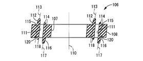
- a passage forming rubber 106 is disposed in the outer peripheral accommodation region 80 formed inside the movable partition wall 54.
- the passage forming rubber 106 is formed of a rubber elastic body having a substantially annular plate shape, and the central axis of the inner peripheral wall 107 and the central axis of the outer peripheral wall 108 are the automobile. It is inclined with respect to the central axis 110 of the passage-forming rubber 106 that coincides with the central axis of the engine mount 10.
- the passage forming rubber 106 has a pair of communication holes 111 and 111 formed at portions opposed to each other in one radial direction.
- the communication hole 111 is formed so as to penetrate the passage forming rubber 106 in the plate thickness direction, and a pair of communication holes 111 and 111 are opposed to each other on the opening on one surface side and the opening on the other surface side. Are formed at positions shifted from each other in one radial direction.
- each communication hole 111 extends linearly while being inclined with respect to the central axis 110 of the passage forming rubber 106.
- the pair of communication holes 111 and 111 are inclined at the same inclination angle and penetrate the passage forming rubber 106.
- Each communication hole 111 has a longitudinal hole cross-sectional shape extending linearly in a direction perpendicular to the axis (up and down in FIG. 3) perpendicular to one radial direction in which the pair of communication holes 111 and 111 face each other. is doing. That is, each communication hole 111 has a dimension (length dimension) in a direction perpendicular to the axis orthogonal to the opposing direction of the pair of communication holes 111, 111, and a dimension (width dimension) in the opposing direction of the pair of communication holes 111, 111. ) Is sufficiently larger than. Each communication hole 111 is formed with a length that does not reach the outer peripheral surface of the passage forming rubber 106.
- the upper valve-like rubber protrusion 112 protrudes upward on one side in the width direction (one direction in the radial direction where the pair of communication holes 111 and 111 face each other) across the communication hole 111.
- the upper valve-like rubber protrusion 112 is formed so as to protrude upward from the opening edge portion of the communication hole 111, and has a plate shape extending along the communication hole 111. Further, the upper valve-like rubber protrusion 112 gradually becomes thinner toward the upper side which is the protruding tip side.
- the end face of the upper valve-like rubber protrusion 112 on the side of the communication hole 111 is an inclined plane that is smoothly connected to the inner surface of one side in the width direction of the communication hole 111 (left side in FIG. 2) without causing irregularities.
- the elastic main shaft 113 extending in the protruding direction of the upper valve-like rubber protrusion 112 has a communication hole 111 side toward the protruding tip side with respect to the axial direction of the engine mount 10 for an automobile. It is inclined.
- an upper buffer protrusion 114 that protrudes upward is integrally formed on the opposite side of the passage forming rubber 106 from the upper valve-like rubber protrusion 112 with the communication hole 111 interposed therebetween.
- the upper buffer protrusion 114 is formed so as to protrude upward from the opening edge of the communication hole 111, and extends along the communication hole 111. Further, like the upper valve-like rubber protrusion 112, the upper buffer protrusion 114 gradually becomes thinner toward the upper side which is the protruding tip side. Further, the upper buffer protrusion 114 has a protruding height smaller than that of the upper valve-shaped rubber protrusion 112 and has a thickness that is the same as or slightly smaller than that of the upper valve-shaped rubber protrusion 112.
- the protruding tip portion of the upper buffer protrusion 114 has at least an end surface on the communication hole 111 side as a curved surface having an arc shape in the longitudinal section.
- an upper concave groove 115 is formed on the upper surface of the passage forming rubber 106.
- the upper groove 115 is a groove opened on the upper surface of the passage forming rubber 106 and is formed so as to surround the communication hole 111, the upper valve-like rubber protrusion 112, and the upper buffer protrusion 114.
- the upper concave groove 115 is formed so as to extend along the base end portion of the upper valve-like rubber protrusion 112 and the base end portion of the upper buffer protrusion 114, and the upper valve-like rubber protrusion 112 and the upper buffer protrusion 114. The distortion of the passage-forming rubber 106 due to the elastic deformation is relaxed by the upper concave groove 115.
- a lower valve-like rubber protrusion 116 protruding downward is integrally formed on the same side of the passage forming rubber 106 as the upper buffer protrusion 114 with the communication hole 111 interposed therebetween.
- the lower valve-like rubber protrusion 116 is formed so as to protrude downward from the opening edge of the communication hole 111, and extends along the communication hole 111 in a cross-sectional shape corresponding to the upper valve-like rubber protrusion 112. Yes. Further, the lower valve-like rubber protrusion 116 gradually becomes thinner toward the lower side which is the protruding tip side.
- the end surface of the lower valve-like rubber protrusion 116 on the side of the communication hole 111 is an inclined plane that is smoothly connected to the inner surface of the other side in the width direction of the communication hole 111 (right side in FIG. 2) without causing irregularities.
- the elastic main shaft 117 extending in the protruding direction of the lower valve-like rubber protrusion 116 has a communication hole 111 toward the protruding tip side with respect to the axial direction of the automobile engine mount 10. Inclined to the side.
- the elastic main shaft 113 of the upper valve-like rubber protrusion 112 and the elastic main shaft 117 of the lower valve-like rubber protrusion 116 extend substantially parallel to each other.
- the passage forming rubber 106 protrudes downward on the opposite side to the lower valve-like rubber protrusion 116 across the communication hole 111, in other words, on the same side as the upper valve-like rubber protrusion 112 across the communication hole 111.
- a lower buffer protrusion 118 is integrally formed.
- the lower buffer protrusion 118 is formed so as to protrude downward from the opening edge portion of the communication hole 111, and extends along the communication hole 111.
- the lower buffer protrusion 118 has a plate shape that gradually becomes thinner toward the lower side on the protruding tip side.
- the lower buffer protrusion 118 has a protrusion height smaller than that of the lower valve-like rubber protrusion 116 and has a thickness that is the same as or slightly smaller than that of the lower valve-like rubber protrusion 116. Further, it is less likely to be elastically deformed than the lower valve-like rubber protrusion 116.
- at the projecting tip of the lower buffer projection 118 at least the end surface on the side of the communication hole 111 is a curved surface having an arc shape in the longitudinal section.
- a lower groove 120 is formed on the lower surface of the passage forming rubber 106.
- the lower concave groove 120 is a concave groove opened on the lower surface of the passage forming rubber 106 and is formed so as to surround the communication hole 111, the lower valve-like rubber protrusion 116, and the lower buffer protrusion 118.
- the lower concave groove 120 is formed so as to extend along the base end portion of the lower valve-like rubber protrusion 116 and the base end portion of the lower buffer protrusion 118, and the lower valve-like rubber protrusion 116 and The distortion of the passage forming rubber 106 due to the elastic deformation of the lower buffer projection 118 is alleviated by the lower concave groove 120.
- the upper and lower valve-like rubber protrusions 112 and 116, the upper and lower buffer protrusions 114 and 118, and the upper and lower concave grooves 115 and 120 are formed in the peripheral portions of the pair of communication holes 111 and 111, respectively.
- the passage-forming rubber 106 having such a structure is accommodated and disposed in the outer peripheral accommodation region 80 formed inside the movable partition wall 54.
- the passage forming rubber 106 is sandwiched and sandwiched between the upper bottom wall portion of the partition wall main body 74 and the bottom plate member 76, and the outer peripheral surface and the inner peripheral surface thereof are at least partially on the inner surface of the outer peripheral housing region 80. It is in contact.
- a communication hole-shaped upper through hole 122 is formed through the upper wall portion of the outer peripheral housing region 80, and a communication hole-shaped lower through hole 124 is formed in the lower wall portion of the outer peripheral housing region 80. It is formed through.
- the communication hole 111 is communicated with the intermediate chamber 94 through the upper through hole 122, and the communication hole 111 is communicated with the equilibrium chamber 92 through the lower through hole 124.
- the passage-forming rubber 106 is disposed with respect to the outer peripheral accommodation region 80 in the movable partition wall 54, so that a through hole constituted by the upper through hole 122, the lower through hole 124, and the outer peripheral accommodation region 80 is formed. It is blocked by the passage forming rubber 106.
- one opening of the communication hole 111 communicates with the intermediate chamber 94 through the upper through hole 122, and the other opening of the communication hole 111 communicates with the equilibrium chamber 92 through the lower through hole 124.
- the passage forming rubber 106 constituting the partition member 48 is formed with a high-frequency orifice passage 126 that communicates the intermediate chamber 94 and the equilibrium chamber 92 with each other using the communication hole 111.
- the high-frequency orifice passage 126 is tuned to a frequency higher than that of the medium-frequency orifice passage 104.
- the high-frequency orifice passage 126 is tuned to a high frequency of about 45 to 100 Hz, which corresponds to a lock-up boom noise caused by engine torque fluctuation. .
- two high-frequency orifice passages 126 tuned to the same frequency are formed. Note that, similarly to the medium frequency orifice passage 104, the high frequency orifice passage 126 can be considered to be formed so as to substantially communicate the pressure receiving chamber 90 and the equilibrium chamber 92 with each other.
- the upper valve-like rubber protrusion 112 and the upper buffer protrusion 114 are inserted into the upper through-hole 122 so as to protrude toward the pressure receiving chamber 90 (intermediate chamber 94), and to the lower through-hole 124.
- a valve-like rubber protrusion 116 and a lower buffer protrusion 118 are inserted and protruded toward the equilibrium chamber 92 side.
- the upper valve-like rubber protrusion 112 is caused by relative pressure fluctuation between the pressure receiving chamber 90 and the equilibrium chamber 92.
- the lower valve-like rubber protrusion 116 is elastically deformed so as to fall down to the communication hole 111 side.
- the opening of the high-frequency orifice passage 126 is covered with the upper valve-like rubber protrusion 112 or the lower valve-like rubber protrusion 116, and the high-frequency orifice passage 126 is switched to the shut-off state.
- the upper valve-like rubber protrusion 112 and the lower valve-like rubber protrusion 116 are valve bodies that switch the high-frequency orifice passage 126 between the communication state and the shut-off state, and at the same time, the initial shape of the high-frequency orifice passage 126 due to their elasticity. It is separated from the opening and serves as a spring means for holding the high-frequency orifice passage 126 in a communicating state in a stationary state.
- the inner circumferential surface of the upper through-hole 122 constitutes a first restricting contact portion that restricts the deformation of the upper valve-like rubber protrusion 112 to the side opposite to the communication hole 111, and the lower through-hole.
- the inner peripheral surface of 124 constitutes a second restricting contact portion that restricts the downward deformation of the lower valve-like rubber protrusion 116 to the side opposite to the communication hole 111.
- the upper buffer protrusion 114 is restricted from tilting to the opposite side of the communication hole 111 by the inner peripheral surface of the upper through hole 122, and the lower buffer protrusion 118 of the lower buffer protrusion 118 is limited by the inner peripheral surface of the lower through hole 124. The fall to the opposite side to the communication hole 111 is restricted.
- the upper valve-like rubber protrusion 112 is brought into contact with the upper buffer protrusion 114 by elastic deformation.
- the lower valve-like rubber protrusion 116 is brought into contact with the lower buffer protrusion 118 by elastic deformation.
- the upper and lower cushioning protrusions 114 and 118 are provided at portions where the upper and lower valve-like rubber protrusions 112 and 116 can approach each other when the high-frequency orifice passage 126 is blocked.
- the automotive engine mount 10 having the above-described structure is configured such that the first mounting member 12 is attached to the power unit 18 by screwing a mounting bolt (not shown) into the bolt hole 24.
- the second mounting member 14 is attached to the vehicle body 20 by bolting the mounting legs 36 of the bracket 32 to the vehicle body 20.
- the flange-like fastening point in the mounting leg portion 36 is located below the lower end of the second mounting member 14, and the second mounting member is mounted while the automobile engine mount 10 is mounted on the vehicle.
- the fastening position between the vehicle body 14 and the vehicle body 20 is set lower than the engine mount 10 for an automobile. Thereby, the equilibrium chamber 92 formed on the lower side in FIG. 1 with respect to the partition member 48 is arranged at a position close to the vehicle body 20 in the automobile engine mount 10.
- the passage forming rubber 106 is accommodated in the partition wall 48 (movable partition wall 54) that partitions the intermediate chamber 94 and the equilibrium chamber 92 in the partition member 48. It is disposed closer to the body 20.
- the axial separation distance d from the center in the plate thickness direction of the passage forming rubber 106 to the fastening point (the lower surface of the mounting leg 36) of the second mounting member 14 with respect to the vehicle body 20 is set to be small. .
- the arrangement position of the passage forming rubber 106 in the axial direction is greatly biased toward the vehicle body 20 side (lower side in FIG. 1 which is the equilibrium chamber 92 side) than the axial center of the second mounting member 14. ing.
- the passage-forming rubber 106 is arranged at a position closer to the fastening direction of the second mounting member 14 to the vehicle body 20 in the axial direction than the fastening point of the first mounting member 12 to the power unit 18. It is installed.
- the passage-forming rubber 106 is disposed in the opening portion on the equilibrium chamber 92 side of the central hole of the partition member main body 50, and the elastic movable film 52 forms the opening on the pressure receiving chamber 90 side of the central hole of the partition member main body 50.
- the passage forming rubber 106 is disposed closer to the vehicle body 20 than the elastic movable film 52. Furthermore, the position of the passage forming rubber 106 in the axial direction is more biased toward the vehicle body 20 than the axial center of the partition member 48.
- the medium frequency orifice passage 104 and the high frequency orifice passage 126 are blocked, and the vibration isolation effect based on the fluid flow through the low frequency orifice passage 100 is efficiently exhibited. ing.
- the medium frequency orifice passage 104 is in a substantially cut-off state in which fluid flow is blocked by blocking the high-frequency orifice passage 126, the reason why the high-frequency orifice passage 126 is blocked will be described below. .
- the upper valve-like rubber protrusion 112 is bent and deformed toward the communication hole 111, and the upper buffer It is brought into contact with the protrusion 114.
- the opening on the intermediate chamber 94 side of the high-frequency orifice passage 126 is covered with the upper valve-like rubber protrusion 112 so that the high-frequency orifice passage 126 is blocked.
- the reason why the upper valve-like rubber protrusion 112 bends toward the communication hole 111 is that the upper valve-like rubber protrusion 112 is formed so as to protrude obliquely toward the communication hole 111.
- the lower valve-like rubber protrusion 116 is bent and deformed toward the communication hole 111, and hits the lower buffer protrusion 118. It can be touched. As a result, the opening on the intermediate chamber 94 side of the high-frequency orifice passage 126 is covered with the upper valve-like rubber protrusion 112 so that the high-frequency orifice passage 126 is blocked.
- the reason why the lower valve-like rubber protrusion 116 bends toward the communication hole 111 is that, like the upper valve-like rubber protrusion 112, the lower valve-like rubber protrusion 116 is formed so as to be inclined and project toward the communication hole 111.
- the elastic deformation to the side opposite to the communication hole 111 is prevented by the second restricting contact portion, and the lower valve-like rubber protrusion 116 is moved to the communication hole 111 side by the action of the negative pressure based on the flow velocity. It is conceivable that the suction force acts.
- the upper valve-like rubber protrusion 112 comes into contact with the upper buffer protrusion 114 and the lower valve-like rubber protrusion 116 comes into contact with the lower buffer protrusion 118.
- the occurrence of a hitting sound is reduced or avoided. That is, since the upper and lower valve-like rubber protrusions 112 and 116 and the upper and lower buffer protrusions 114 and 118 are all formed of a rubber elastic body, the impact force at the time of contact is applied to the valve-like rubber protrusions 112 and 116 and the buffering shock. It is attenuated by the elastic deformation of the protrusions 114 and 118, and the abnormal noise at the time of contact is reduced.
- the end portion on the communication hole 111 side where the valve-like rubber projections 112 and 116 abut at the projecting tip portions of the buffer projections 114 and 118 are curved surfaces having an arcuate vertical cross-sectional shape. Therefore, the contact area in the initial contact of the valve-like rubber protrusions 112 and 116 with the buffer protrusions 114 and 118 is kept small, and the contact area gradually increases. Therefore, the buffering action at the time of contact is more effectively exhibited, and the hitting sound generated when the high-frequency orifice passage 126 is blocked is more advantageously reduced.
- a movable partition wall 54 that supports the passage forming rubber 106 is disposed at a position separating the intermediate chamber 94 and the equilibrium chamber 92.
- the axial separation distance d between the passage-forming rubber 106 and the fastening point (the lower surface of the mounting leg portion 36 in the bracket 32) that fixes the second mounting member 14 to the vehicle body 20 is the path.
- the forming rubber 106 is set to be smaller than the case where the forming rubber 106 is disposed in the partition between the pressure receiving chamber 90 and the equilibrium chamber 92.
- the impact force generated by the contact between the valve-like rubber protrusions 112 and 116 and the buffer protrusions 114 and 118 at the time of vibration input is substantially constant regardless of the arrangement position of the passage forming rubber 106 in the axial direction. Therefore, as the separation distance between the position of the passage forming rubber 106 serving as the point of application of the impact force and the fastening point of the second mounting member 14 to the vehicle body 20 becomes smaller, the fastening is caused by the impact force. The moment exerted on the point is kept small.
- the valve-like rubber protrusions 112 and 116 and the buffer protrusions 114 and 118 It is possible to reduce or avoid the transmission of abnormal noise and vibration generated by the contact with the vehicle body 20.
- the passage forming rubber 106 is disposed in the movable partition wall 54, and the movable partition wall 54 is supported by the second mounting member 14 with respect to the partition member main body 50 and the elastic support cylinder portion 64 and the support rubber. It is elastically supported via an elastic body 58. Therefore, the impact force caused by the contact between the valve-like rubber protrusions 112 and 116 and the buffer protrusions 114 and 118 is buffered by the elastic support cylinder portion 64 and the support rubber elastic body 58 on the transmission path to the vehicle body 20. It is like that. Accordingly, it is possible to more effectively reduce the generation of abnormal noise caused by the transmission of the impact force to the vehicle body 20.
- the partition member main body 50 is fitted to the second mounting member 14 via the seal rubber layer 40, the sound of hitting by the contact between the valve-like rubber protrusions 112, 116 and the buffer protrusions 114, 118 is achieved. Is also buffered and reduced by the seal rubber layer 40.
- the movable partition wall 54 and the partition member 48 are axially aligned with the resonance frequency of the mass-spring system (the natural frequency of the movable partition wall 54) being tuned to a higher frequency. Minor displacement at is limited. Further, the annular rubber plate 86 is held in a state of being pressed against the bottom plate member 76 by the urging force of the coil spring 88, and the lower short-circuit hole 84 is blocked. As a result, the amount of fluid flow in the low-frequency orifice passage 100 is more advantageously ensured, and the intended vibration isolation effect is effectively exhibited.
- the vibration isolation effect (low dynamic spring effect) based on the fluid flow action is exhibited.
- the low frequency orifice passage 100 is substantially blocked by an anti-resonant action, and the high frequency orifice passage 126 is kept in communication. Further, the hydraulic pressure absorption due to the minute displacement of the movable partition wall 54 and the partition member 48 is prevented, and the one-way valve is held in the shut-off state. As a result, the amount of fluid flow through the medium frequency orifice passage 104 is advantageously ensured, and the intended vibration isolation effect is effectively exhibited.
- the medium frequency orifice passage 104 is formed by utilizing the end of the low frequency orifice passage 100 on the pressure receiving chamber 90 side. Therefore, the orifice passages 100 and 104 can be formed in a space efficient manner, and the orifice passages 100 and 104 can be formed with a large degree of design freedom.
- both the low frequency orifice passage 100 and the medium frequency orifice passage 104 are blocked by anti-resonance. Further, the hydraulic pressure absorption due to the minute displacement of the movable partition wall 54 and the partition member 48 is prevented, and the one-way valve is held in the shut-off state. As a result, fluid flow through the high-frequency orifice passage 126 is efficiently generated, and the intended vibration-proofing effect is effectively exhibited.
- the negative pressure in the pressure receiving chamber 90 transmitted to the intermediate chamber 94 is eliminated as quickly as possible by the inflow of fluid from the equilibrium chamber 92, and the cavitation error that occurs due to the negative pressure in the pressure receiving chamber 90. Sound or the like can be reduced or avoided.
- the annular rubber plate 86 is pressed against the bottom plate member 76 by the biasing force of the coil spring 88, and the lower short-circuit hole 84 is blocked. Therefore, in this embodiment, the annular rubber plate 86 is accommodated in the movable partition wall 54. Therefore, the impact force caused by the contact of the annular rubber plate 86 is buffered by the elastic support cylinder 64, the support rubber elastic body 58, and the seal rubber layer 40 on the path transmitted to the vehicle body 20. Further, the generation of hitting sound due to the contact of the annular rubber plate 86 is reduced or avoided. Further, since the valve body is an annular rubber plate 86 formed of a rubber elastic body, the hitting sound at the time of contact is also buffered and reduced by the elastic deformation of the annular rubber plate 86 itself. Yes.
- the elastic movable film 52 formed of a rubber elastic body and the passage forming rubber 106 are disposed in the central hole of the partition member body 50 that is made hard. Therefore, by fitting and fixing the partition member main body 50 to the second mounting member 14, the elastic movable film 52 and the passage forming rubber 106 can be easily assembled at predetermined positions of the second mounting member 14.
- FIG. 4 shows an automobile engine mount 128 as a second embodiment of the fluid filled type vibration damping device having a structure according to the present invention.
- members and portions that are substantially the same as those of the first embodiment are denoted by the same reference numerals in the drawings, and the description thereof is omitted.
- the automobile engine mount 128 includes a partition member 130.
- the partition member 130 includes a partition member main body 132, an elastic movable film 134, and a movable partition wall 136.
- the partition member main body 132 has a structure in which the partition member main body 50 in the first embodiment is turned upside down.
- a support piece 138 corresponding to the support piece 56 is integrally formed at the upper end portion, and the lower end.
- a locking claw 140 corresponding to the locking claw 70 is formed integrally with the part.
- a support rubber elastic body 142 having a substantially annular plate shape is superimposed on the lower surface of the support piece 138, and an upper outer peripheral support portion 144 that protrudes downward is integrated with the outer peripheral edge portion of the support rubber elastic body 142. Is formed.
- an elastic movable film 134 is disposed in the lower opening of the central hole in the partition member main body 132.
- the elastic movable film 134 has a structure in which the elastic movable film 52 of the first embodiment is turned upside down, and an elastic support cylindrical portion 146 corresponding to the elastic support cylindrical portion 64 protrudes upward.
- a lower outer peripheral support portion 147 protruding upward is integrally formed at the outer peripheral edge portion of the elastic support cylinder portion 146.
- a support fitting 148 having a structure in which the support fitting 68 of the first embodiment is turned upside down is fixed to the elastic movable film 134.
- the central portion of the support metal 148 is vulcanized and bonded in an embedded state to the elastic support cylinder portion 146 of the elastic movable film 134, and the elastic movable film 134 is formed as an integrally vulcanized molded product including the support metal 148.
- the elastic movable film 134 having such a structure is configured such that the outer peripheral portion of the support fitting 148 is superimposed on the lower surface of the partition member main body 132 and is fixed by the engagement of the locking claw 140 and the locking hole 72. It is attached to the partition member main body 132.
- a movable partition wall 136 is disposed between the axially opposed surfaces of the support rubber elastic body 142 and the elastic support cylinder portion 146.
- the movable partition wall 136 has a structure in which a disk-shaped cover plate member 154 is superimposed from above on a partition wall main body 152 having a thick and substantially petri dish shape.
- the movable partition wall 136 is assembled to the partition member main body 132 by elastically supporting the outer peripheral edge portion between the support rubber elastic body 142 and the elastic support cylinder portion 146.
- the partition member 130 having such a structure is disposed in the fluid chamber 46, and the partition member main body 132 is fitted and fixed to the second mounting member 14.
- the pressure receiving chamber 90 and the equilibrium chamber 92 are formed on both sides of the partition member 130, and the intermediate chamber 94 is formed inside the partition member 130.
- the pressure receiving chamber 90 and the intermediate chamber 94 are partitioned by the movable partition wall 136, and the intermediate chamber 94 and the equilibrium chamber 92 are partitioned by the elastic movable film 134.
- An intermediate frequency orifice passage 104 tuned to an intermediate frequency corresponding to idling vibration is formed so as to communicate the intermediate chamber 94 and the equilibrium chamber 92.
- a dynamic damper including the movable partition wall 136 as a mass system and including the support rubber elastic body 142 and the elastic support cylinder portion 146 as a spring system is configured, and the natural frequency of the movable partition wall 136 corresponds to idling vibration. Tuned to frequency. Further, the hydraulic pressure fluctuation due to the input of high frequency vibration corresponding to the lock-up booming sound is transmitted between the intermediate chamber 94 and the equilibrium chamber 92 by elastic deformation of the elastic movable film 134.
- annular rubber plate 86 and a coil spring 88 are disposed in the central housing region 78, and the annular rubber plate 86 and the coil spring 88 constitute a one-way valve.
- a passage forming rubber 106 is disposed in the outer peripheral housing region 80, and a plurality of high-frequency orifice passages 126 are formed using the communication holes 111 of the passage forming rubber 106.
- the high frequency orifice passage 126 is tuned to a high frequency range corresponding to a lock-up booming noise.
- the upper and lower valve-like rubber protrusions 112 and 116 are elastically deformed so as to bend toward the communication hole 111 by the action of the hydraulic pressure, and the high-frequency orifice passage 126 becomes the valve-like rubber. It is blocked by the protrusions 112 and 116. As a result, the relative pressure fluctuation between the pressure receiving chamber 90 and the equilibrium chamber 92 is efficiently induced, and the anti-vibration effect of the low frequency orifice passage 100 is exhibited.
- FIG. 5 shows an automobile engine mount 156 as a third embodiment of the fluid filled type vibration damping device according to the present invention.
- the automobile engine mount 156 includes a partition member 158, and the partition member 158 includes a partition member main body 160 and a housing member 162.
- the partition member main body 160 has a substantially disk shape as a whole, and has a circular central recess 164 that opens to the lower surface.
- a circumferential groove 166 extending in the circumferential direction with a predetermined length is formed in the outer circumferential portion of the partition member main body 160 so as to open to the outer circumferential surface.
- a disc-shaped accommodation member 162 is assembled in the central recess 164 of the partition member main body 160.
- a pair of housing recesses opened on the upper surface are formed at portions facing in one radial direction.
- the accommodating member 162 is fitted into the central recess 164 of the partition member main body 160, the opening of each accommodating recess is covered by the central portion of the partition member main body 160, and the accommodating regions 168a and 168b are formed.
- the upper through holes 170 are formed through the upper bottom wall portions of the storage regions 168a and 168b, respectively, and the lower through holes 172 are formed through the lower bottom wall portions of the storage regions 168a and 168b, respectively.
- the storage areas 168a and 168b have the same planar shape and have different axial dimensions, and the axial dimensions of the storage area 168a are larger than the axial dimensions of the storage area 168b. It has become.
- the partition member 158 having such a structure is disposed in the fluid chamber 46 and supported by the second mounting member 14.
- a pressure receiving chamber 90 and an equilibrium chamber 92 in which an incompressible fluid is sealed are formed on both sides of the partition member 158.
- the opening of the circumferential groove 166 is covered with the second mounting member 14, thereby forming a low frequency orifice passage 100 that allows the pressure receiving chamber 90 and the equilibrium chamber 92 to communicate with each other.
- the low frequency orifice passage 100 is tuned to a frequency corresponding to the engine shake.
- the passage forming rubber 174a is disposed in the accommodation region 168a, and the passage formation rubber 174b is disposed in the accommodation region 168b.
- the passage forming rubber 174 has a substantially rectangular block shape as a whole, and the thickness dimension in the axial direction of the passage forming rubber 174a is larger than the thickness dimension in the axial direction of the passage forming rubber 174b. Is set.
- a linearly extending communication hole 175 is formed through the central portion of the passage forming rubber 174.
- the communication hole 175 has a basic structure substantially the same as that of the communication hole 111 shown in the first embodiment, and the dimension in the through direction of the communication hole 175a formed in the passage forming rubber 174a. However, it is larger than the dimension in the penetration direction of the communication hole 175b formed in the passage forming rubber 174b.
- the first high-frequency orifice passage 176 is formed using the communication hole 175a
- the second high-frequency orifice passage 178 is formed using the communication hole 175b.
- the first high-frequency orifice passage 176 is tuned to medium-frequency small to medium-amplitude vibration corresponding to idling vibration
- the second high-frequency orifice passage 178 is tuned to high-frequency small-amplitude vibration corresponding to traveling noise. ing.
- two high-frequency orifice passages are formed in the automobile engine mount 156, and the tuning frequencies of these high-frequency orifice passages are different from each other.
- the upper valve-like rubber protrusion 180a and the upper buffer protrusion 114a are disposed at the opening on the pressure receiving chamber 90 side of the first high-frequency orifice passage 176 with the communication hole 175a interposed therebetween, and the first high-frequency orifice passage.
- a lower valve-like rubber protrusion 116a and a lower buffer protrusion 118a are disposed in the opening of the balance chamber 92 side of 176 with the communication hole 175a interposed therebetween.
- an upper valve-like rubber protrusion 180b and an upper buffer protrusion 114b are disposed at the opening of the second high-frequency orifice passage 178 on the pressure receiving chamber 90 side with the communication hole 175b interposed therebetween, and the second high-frequency orifice passage 178 is disposed.
- the lower valve-like rubber protrusion 116b and the lower buffer protrusion 118b are disposed in the opening on the equilibrium chamber 92 side with the communication hole 175b interposed therebetween. Since the upper valve-like rubber protrusion 180 has substantially the same structure as the upper valve-like rubber protrusion 112 in the first embodiment, description of the basic structure is omitted.
- the upper valve-like rubber protrusion 180a is thinner than the upper valve-like rubber protrusion 180b in the opposing direction of the pair of communication holes 175a and 175b.
- the spring constants of the upper valve-like rubber protrusion 180a and the upper valve-like rubber protrusion 180b are different, and the upper valve-like rubber protrusion 180a is more easily deformed than the upper valve-like rubber protrusion 180b.
- the lower valve-like rubber protrusion 116a is thinner than the lower valve-like rubber protrusion 116b.
- the spring constants of the lower valve-like rubber protrusion 116a and the lower valve-like rubber protrusion 116b are different, and the lower valve-like rubber protrusion 116a is more easily deformed than the lower valve-like rubber protrusion 116b.
- the upper valve-like rubber protrusion 180 has a larger projecting dimension than the lower valve-like rubber protrusion 116. As a result, the upper valve-like rubber protrusion 180 is more likely to be elastically deformed than the lower valve-like rubber protrusion 116. Note that the plate thickness dimension of the upper valve-like rubber protrusion 180 may be set smaller than the plate thickness dimension of the lower valve-like rubber protrusion 116. In short, the spring constants of the upper valve-like rubber protrusion 180 and the lower valve-like rubber protrusion 116 are different from each other based on the difference in cross-sectional shape.
- the upper valve-shaped rubber protrusion 180 is elastically deformed to block the first and second high-frequency orifice passages 176 and 178, and the lower valve-shaped rubber protrusion 116 is elastically deformed to the first.
- the blocking conditions for blocking the second high-frequency orifice passages 176 and 178 can be made different from each other.
- the upper and lower valve-like rubber protrusions 180 and 116 are elastically deformed toward the communication hole 175, and the first and second The high-frequency orifice passages 176 and 178 are blocked. Thereby, the fluid flow amount of the low frequency orifice passage 100 can be ensured, and an effective vibration isolation effect can be obtained.
- the deformation of the upper and lower valve-like rubber protrusions 180a and 116a is reduced or released, and the first high-frequency orifice passage 176 is switched to the communication state.
- the intended vibration isolation effect is exhibited.
- the second high-frequency orifice passage 178 is held in a shut-off state in order to ensure a large fluid flow rate in the first high-frequency orifice passage 176.
- the cross-sectional shapes and forming materials of the upper and lower valve-like rubber protrusions 180a and 116a and the upper and lower valve-like rubber protrusions 180b and 116b are made different so that the blocking conditions such as the spring constant are made different from each other.
- the communication state of the first high-frequency orifice passage 176 and the shut-off state of the second high-frequency orifice passage 178 can be expressed simultaneously.
- the upper valve-like rubber protrusion 180 projecting toward the pressure receiving chamber 90 side is formed with a larger projecting dimension than the lower valve-like rubber protrusion 116 projecting toward the equilibrium chamber 92 side.
- the elastic deformation of the protrusion 180 is more likely to occur than the elastic deformation of the lower valve-like rubber protrusion 116. Accordingly, the closing operation condition set for the upper valve-like rubber protrusion 180 (the magnitude of the external force necessary for the closing operation) and the closing operation condition set for the lower valve-like rubber protrusion 116 are mutually Is different.
- the fluid flow from the equilibrium chamber 92 to the pressure receiving chamber 90 is more likely to occur than the fluid inflow from the pressure receiving chamber 90 to the equilibrium chamber 92, and the pressure receiving chamber 90 is easily maintained at a higher pressure than the equilibrium chamber 92. ing. As a result, it is possible to reduce the decrease in the internal pressure of the pressure receiving chamber 90 due to the input of shocking vibration load, and to prevent the occurrence of cavitation.
- FIG. 6 shows an automobile engine mount 182 as a fourth embodiment of the fluid filled type vibration damping device according to the present invention.
- the automotive engine mount 182 has the same basic structure as the automotive engine mount 10 shown in the first embodiment, and a partition member 183 is employed instead of the partition member 48. Further, the partition member 183 is provided with a movable partition wall 184 instead of the movable partition wall 54.
- the movable partition wall 184 includes a partition body 186 having a shallow shallow dish shape and a disk-shaped bottom plate member 188 that covers the opening of the partition body 186, and is formed into a hollow disk as a whole. ing.
- a cylindrical accommodation region 190 is formed between the partition wall main body 186 and the bottom plate member 188.
- An upper through hole 192a and an upper through hole 192b extending in parallel with each other in one direction perpendicular to the axis are formed in the axially upper wall portion of the housing region 190.
- Each of the upper through hole 192a and the upper through hole 192b has a substantially rectangular shape in a plan view and penetrates the upper bottom wall portion of the partition wall body 186.
- the upper side through-hole 192a is set to have a smaller length in the longitudinal direction than the upper side through-hole 192b.
- a lower side through hole 194a is formed in a position corresponding to the upper side through hole 192a in the wall portion on the lower side in the axial direction of the housing region 190, and a lower side through hole is provided in a position corresponding to the upper side through hole 192b. 194b is formed.
- the upper through hole 192a and the lower through hole 194a have substantially the same hole cross-sectional shape, and the upper through hole 192b and the lower through hole 194b have substantially the same hole cross sectional shape.
- a passage forming rubber 196 is accommodated in the accommodation area 190.
- the passage forming rubber 196 has a substantially disk shape and includes a communication hole 198 a and a communication hole 198 b.
- Each of the communication hole 198a and the communication hole 198b penetrates the passage-forming rubber 196 in the thickness direction, is elongated in one direction perpendicular to the axis in plan view, and is formed parallel to each other at a predetermined distance.
- the communication hole 198a is set to have a smaller length in the longitudinal direction than the communication hole 198b.
- the communication hole 198a is arranged closer to the outer periphery than the communication hole 198b in the direction perpendicular to the axis (the left-right direction in FIG. 7) facing the communication hole 198b.
- the communication holes 198a and 198b penetrate the passage forming rubber 196 while being inclined in the same direction as the communication hole 111 of the first embodiment.
- upper and lower valve-like rubber protrusions 112 and 116 and upper and lower buffer protrusions 114 and 118 are formed on both sides in the width direction of the communication hole 198a and the communication hole 198b, respectively.
- the upper and lower valve-like rubber protrusions 112a and 116a and the upper and lower buffer protrusions 114a and 118a formed on both sides in the width direction of the communication hole 198a are upper and lower valve-like rubber protrusions 112b formed on both sides in the width direction of the communication hole 198b.
- 116b and the upper and lower buffer projections 114b and 118b, the length of the communication hole 198 in the longitudinal direction (vertical direction in FIG. 7) is made smaller.
- the movable partition wall 184 is formed by disposing the passage forming rubber 196 in the accommodation region 190.
- the movable partition wall 184 is elastically supported between the support rubber elastic body 58 and the elastic support cylinder portion 64 in the same manner as the movable partition wall 54 of the first embodiment.
- the communication hole 198a and the communication hole 198b formed in the passage forming rubber 196 are communicated with the equilibrium chamber 92 and the intermediate chamber 94 through the upper and lower through holes 192 and 194, respectively, and the equilibrium chamber 92 is communicated by the communication hole 198a.
- first high-frequency orifice passage 200 that connects the intermediate chamber 94 to each other and a second high-frequency orifice passage 202 that connects the equilibrium chamber 92 and the intermediate chamber 94 to each other are formed by the communication holes 198b. Yes.
- the first and second high-frequency orifice passages 200 and 202 constitute the high-frequency orifice passage of the present embodiment.
- the first high-frequency orifice passage 200 has the same passage length and smaller passage cross-sectional area than the second high-frequency orifice passage 202, and the tuning frequency is set to a low frequency.
- an anti-vibration effect against low to medium frequency vibrations by the low frequency orifice passage 100 and the medium frequency orifice passage 104 is exhibited, and the first and second high frequency orifice passages are provided.
- 200 and 202 provide an anti-vibration effect against high-frequency vibration.
- the vibration-proofing effect of the orifice passages 200 and 202 against a plurality of types of vibrations having different frequencies in a high frequency range is improved.
- the passage-forming rubber 196 has a disc shape without a central hole. Therefore, the degree of freedom of the position and number of the communication holes is increased, and it is possible to realize an engine mount that is more suitable for the intended vibration isolation characteristics.
- FIG. 8 shows an automobile engine mount 204 as a fourth embodiment of the fluid filled type vibration damping device having a structure according to the present invention. Since the automobile engine mount 204 has the same structure as the automobile engine mount 156 according to the third embodiment, the description thereof is omitted by attaching the same reference numerals in the drawing.
- the automobile engine mount 204 has a partition member 206.
- the partition member 206 has substantially the same structure as the partition member main body 160 in the above-described embodiment, and a communication hole 208 that penetrates the upper bottom wall portion of the central recess 164 in the axial direction in the radially intermediate portion. Is formed.
- One opening portion of the communication hole 208 communicates with the pressure receiving chamber 90 and the other opening portion communicates with the equilibrium chamber 92, and the communication hole 208 forms a high-frequency orifice passage 210.
- the high-frequency orifice passage 210 is tuned to a frequency corresponding to idling vibration.
- a plate-like rubber valve 212 as a valve body is disposed at the opening of the high-frequency orifice passage 210.
- the plate-like rubber valve 212 is formed of a rubber elastic body having a substantially disc shape, and has a diameter larger than the diameter of the communication hole 208.
- the plate-like rubber valve 212 is integrally formed with a locking portion 214 that protrudes on the opposite side to the partition member 206 in the plate thickness direction.
- the locking portion 214 has a substantially frustoconical tip portion that gradually decreases in diameter toward the protruding tip side, a base end side of the tip portion, and the plate-like rubber valve 212, and has a smaller diameter than the base end portion of the tip portion. It is set as the structure which was integrally provided with the column-shaped connection part made into.
- the plate-like rubber valve 212 is supported by a plate spring 216 as a spring means.
- the leaf spring 216 is formed of a metal material having a longitudinal plate shape.
- the plate-like rubber valve 212 is fixed to one end portion in the longitudinal direction, and the other end portion in the longitudinal direction is fixed to the partition member 206. Has been. Thereby, the plate-like rubber valve 212 is elastically supported with respect to the partition member 206 via the leaf spring 216.
- an inclined portion is provided in the longitudinal intermediate portion of the leaf spring 216, and the plate-like rubber valve 212 fixed to the longitudinal end portion of the leaf spring 216 is separated from the partition member 206 in an initial state where no external force acts. Separated in the axial direction.
- the plate-like rubber valve 212 is allowed to move in the approach direction and the separation direction with respect to the opening of the high-frequency orifice passage 210 by the elastic deformation of the leaf spring 216.
- the means for fixing the leaf spring 216 to the partition member 206 is not particularly limited, and for example, means such as fixing with a rivet or screw, adhesion with an adhesive, welding, etc. may be employed.
- the plate-like rubber valve 212 is fixed to the plate spring 216 by locking the locking portion 214, but may be fixed by means such as vulcanization adhesion.
- a pair of plate-like rubber valves 212 and 212 are spaced apart from both openings of the high-frequency orifice passage 210 and are elastically supported by independent plate springs 216 and 216, respectively.
- a pair of leaf springs 216 and 216 each having a plate-like rubber valve 212 are attached to both surfaces of the partition member 206.
- a vibration isolation effect based on fluid flow through the low-frequency orifice passage 100 is exhibited at the time of vibration input in a frequency range corresponding to engine shake, At the time of vibration input in a frequency range corresponding to idling vibration, an anti-vibration effect based on fluid flow through the high-frequency orifice passage 210 is exhibited.
- the spring means is constituted by the metal leaf spring 216, the durability of the spring means can be improved, and sufficient reliability can be ensured even by repeated operation. Furthermore, by using a metal whose attenuation is extremely smaller than that of the rubber elastic body, the valve body can be operated quickly, and the vibration isolation effect exhibited by the low frequency orifice passage 100 can be advantageously obtained. . Furthermore, by using a combination of a metal spring means (plate spring 216) and a valve body (plate rubber valve 212) formed of a rubber elastic body, the advantageous effects of the metal spring as described above can be enjoyed. However, the advantageous effect of the rubber valve can also be obtained.
- the contact sound generated when the high-frequency orifice passage 210 is blocked can be suppressed by the buffering action of the plate-like rubber valve 212, and the adhesiveness due to the elastic deformation of the plate-like rubber valve 212 is utilized.
- a reliable shut-off of the high-frequency orifice passage 210 can also be realized.
- valve bodies are disposed on both sides of the pressure receiving chamber side and the equilibrium chamber side, but the valve body may be disposed only on one side.
- the valve body may be provided only on the pressure receiving chamber side.
- the fluid inflow from the equilibrium chamber side to the pressure receiving chamber side is advantageously generated rather than the fluid inflow from the pressure receiving chamber side to the equilibrium chamber side through the high-frequency orifice passage. Therefore, the hydraulic pressure in the pressure receiving chamber is set to be relatively high with respect to the hydraulic pressure in the equilibrium chamber, and generation of abnormal noise due to the negative pressure in the pressure receiving chamber can be prevented.
- a structure is shown in which a pair of communication holes are arranged to face each other in one radial direction.
- a pair of communication holes are arranged to face each other in one radial direction.
- only one communication hole may be formed.
- three or more communication holes may be formed, and the number of valve bodies and spring means is appropriately set accordingly.
- the two communication holes do not necessarily have to be formed at positions facing each other in one radial direction.
- the structure in which the upper and lower valve-like rubber protrusions are inclined in advance toward the communication hole side is shown.
- the protrusion direction of the valve-like rubber protrusion is relative to the mount axis direction. And may be formed so as to be parallel.
- the valve-like rubber protrusion has an elastic main shaft extending in the protruding direction that is gradually inclined toward the communicating hole side toward the protruding tip side. It is desirable. More preferably, like the upper and lower valve-like rubber protrusions shown in the first to fourth embodiments, both the surface on the communicating hole side and the surface opposite to the communicating hole are on the projecting tip side. The inclined surface is gradually inclined toward the communication hole.
- a valve-like rubber protrusion protruding from the peripheral edge of the circular hole 186 toward the pressure receiving chamber 90 is directly fixed to the upper surface of the partition member 184 shown in the fifth embodiment, The circular hole 186 may be blocked by elastic deformation of the valve-like rubber protrusion.
- the communication hole extending linearly is exemplified as the communication hole.
- a communication hole curved in the circumferential direction or a wavy communication hole can be applied.
- the communication hole is inclined with respect to the axial direction, this inclination is not always necessary.
- valve-like rubber protrusions are formed on one side across the communication hole, but the valve-like rubber protrusions are formed on both sides, and these valve-like rubbers are formed.
- the high-frequency orifice passage may be blocked by the elastic deformation of the protrusions toward the communication hole.
- the upper valve-like rubber protrusion 112 and the upper valve-like rubber protrusion 180 are provided, and the first valve-like rubber protrusion 112 and the upper valve-like rubber protrusion 112, 180 have a first difference due to a difference in spring constant due to a difference in cross-sectional shape.
- the high-frequency orifice passage 176 and the second high-frequency orifice passage 178 have different blocking conditions.
- the separation distance from the communication hole in the initial state of the valve-like rubber protrusion having the same cross-sectional shape is By making them different, the closing conditions of the plurality of high-frequency orifice passages can be made different from each other.
- the blocking conditions can be made different by changing the material for forming the valve-like rubber protrusions having the same shape.
- the communication hole does not necessarily need to be completely closed when the valve body is closed.
- the valve body approaches the opening of the communication hole against the urging force of the spring means and has a minute gap.
- the flow resistance is remarkably increased in the constricted region (gap) formed between the valve body and the opening of the communication hole, and the communication hole is maintained in a substantially blocked state. It may be like this.
- the medium frequency orifice passage 104 is formed by using a part of the low frequency orifice passage 100. It may be formed completely independently of the orifice passage 100.
- the short-circuit mechanism (one-way valve) constituted by the annular rubber plate 86 and the coil spring 88 shown in the first and second embodiments is not necessarily required.
- the urging means of the pressure relief valve is not necessarily limited to a metal coil spring, and for example, rubber, elastic synthetic resin, or a leaf spring can be used. Also, as a pressure relief valve, not only a rubber elastic body but also a hard material such as metal or resin can be used.
- the dynamic damper is configured including the movable partition wall 54 (184) and the support rubber elastic body 58, and the partition member 48 (183) and the seal rubber layer. 40 is further configured to further improve the degree of freedom of tuning and further improve the anti-vibration effect against high-frequency input vibrations.
- these dynamic damper configurations are not necessarily limited. Not necessary.
- the natural frequency of the movable partition wall 54 (184) and the partition member 48 (183) is tuned to a frequency range that is out of the frequency range of the vibration to be isolated, and the movable partition wall 54 (184) and the partition member 48 ( 183) may not substantially function as a dynamic damper.
- the housing in which the movable plate is accommodated does not necessarily have to be elastically supported with respect to the partition member main body 50. Further, the partition member 48 (183) does not need to be elastically supported with respect to the second mounting member 14.
- the intermediate chamber 94 and the equilibrium chamber 92 are communicated with each other by using the end of the low frequency orifice passage 100 on the side of the equilibrium chamber 92 that is out of the medium frequency orifice passage 104.
- An orifice passage may be formed.
- a further orifice that communicates the pressure receiving chamber 90 and the intermediate chamber 94 using the end of the low frequency orifice passage 100 on the side of the pressure receiving chamber 90 that is out of the medium frequency orifice passage 104.
- a passage may be formed.
- passage forming rubbers 106 and 174 may be, for example, a disk shape or a rectangular plate shape.
- the present invention is not only applied to a fluid-filled vibration isolator for automobiles, but can also be applied to a fluid-filled vibration isolator used for, for example, railway vehicles, industrial vehicles, motorcycles, and the like. It is. Furthermore, the present invention can be applied to various fluid-filled vibration damping devices such as a body mount and a member mount in addition to the engine mount.
Landscapes
- Engineering & Computer Science (AREA)
- General Engineering & Computer Science (AREA)
- Mechanical Engineering (AREA)
- Combined Devices Of Dampers And Springs (AREA)
Abstract
Description
Claims (11)
- 第一の取付部材と第二の取付部材を本体ゴム弾性体によって連結して、壁部の一部が該本体ゴム弾性体で構成された受圧室と壁部の一部が可撓性膜で構成された平衡室を形成し、それら受圧室と平衡室に非圧縮性流体を封入すると共に、それら受圧室と平衡室を相互に連通するオリフィス通路を形成した流体封入式防振装置において、
前記受圧室と前記平衡室を仕切る仕切部材を前記第二の取付部材によって支持せしめると共に、該仕切部材に低周波オリフィス通路と該低周波オリフィス通路よりも高周波数にチューニングされた高周波オリフィス通路とを形成して、それら低周波オリフィス通路と高周波オリフィス通路を含んで前記オリフィス通路を構成する一方、該高周波オリフィス通路の少なくとも一方の開口部に弁体を配置すると共に、初期形状において該弁体を該高周波オリフィス通路の開口部から離隔せしめて該高周波オリフィス通路を連通状態に保持するばね手段を設けて、該受圧室と該平衡室の相対的な圧力変動に基づいて該ばね手段の保持力に抗して該弁体が該高周波オリフィス通路の開口部に接近し該高周波オリフィス通路を遮断するようにしたことを特徴とする流体封入式防振装置。 - 前記高周波オリフィス通路の開口部分には前記受圧室側と前記平衡室側の少なくとも一方に向かって突出する弁状ゴム突起が形成されており、該弁状ゴム突起によって前記弁体と前記ばね手段が一体的に構成されている請求項1に記載の流体封入式防振装置。
- 前記仕切部材に対して前記受圧室と前記平衡室を連通する透孔を形成して、該透孔を遮断する通路形成用ゴムを該仕切部材に対して支持させると共に、該通路形成用ゴムには、該透孔を通じて該受圧室と該平衡室に連通された連通孔を形成して、該連通孔によって前記高周波オリフィス通路を形成すると共に、該連通孔の開口周縁部には、前記弁状ゴム突起を該通路形成用ゴムと一体形成した請求項2に記載の流体封入式防振装置。
- 前記高周波オリフィス通路の開口部への接近方向と反対側への前記弁状ゴム突起の弾性変形を規制する規制当接部を設けた請求項2又は3に記載の流体封入式防振装置。
- 前記高周波オリフィス通路が複数形成されており、それら複数の高周波オリフィス通路の各開口部に前記弁体が設けられている請求項1~4の何れか1項に記載の流体封入式防振装置。
- 前記複数の高周波オリフィス通路を二つ以上の異なる周波数にチューニングした請求項5に記載の流体封入式防振装置。
- 前記弁体を前記高周波オリフィス通路の前記受圧室側開口部分と前記平衡室側開口部分の両方に設けた請求項1~6の何れか1項に記載の流体封入式防振装置。
- 前記複数の弁体が前記高周波オリフィス通路を互いに異なる条件で遮断するようにした請求項5~7の何れか1項に記載の流体封入式防振装置。
- 前記複数の弁体をそれぞれ独立した前記ばね手段によって弾性的に位置決め保持すると共に、それら複数のばね手段のばね定数を互いに異なるようにチューニングすることにより、該複数の弁体が前記高周波オリフィス通路を互いに異なる条件で遮断するようにした請求項8に記載の流体封入式防振装置。
- 前記高周波オリフィス通路の開口部分における前記弁体の接近部位に緩衝突起を形成した請求項1~9の何れか1項に記載の流体封入式防振装置。
- 前記第二の取付部材を筒形状として、該第二の取付部材の一方の開口部側に前記第一の取付部材を離隔配置すると共に、該第二の取付部材の防振対象部材に対する固定部を該第二の取付部材における該第一の取付部材と反対の開口部側に設ける一方、該第二の取付部材の軸方向に前記仕切部材を挟んで該第一の取付部材側に前記受圧室を形成し反対側に前記平衡室を形成すると共に、該仕切部材の内部に中間室を形成する一方、該中間室と該受圧室との間に弾性可動膜を配設すると共に、該仕切部材において該中間室と該平衡室とを隔てる隔壁部分に該中間室と該平衡室を連通する前記高周波オリフィス通路を形成し、更に該高周波オリフィス通路の開口部分に前記弁体を配設することにより、該第二の取付部材の軸方向で該弁体を該弾性可動膜に比して、該第二の取付部材の該防振対象部材に対する固定部が設けられた方の開口部側に位置せしめた請求項1~10の何れか1項に記載の流体封入式防振装置。
Priority Applications (4)
| Application Number | Priority Date | Filing Date | Title |
|---|---|---|---|
| JP2010513569A JP5432132B2 (ja) | 2008-12-25 | 2009-11-04 | 流体封入式防振装置 |
| US12/865,970 US8424854B2 (en) | 2008-12-25 | 2009-11-04 | Fluid-filled type vibration damping device |
| DE112009001871.8T DE112009001871B4 (de) | 2008-12-25 | 2009-11-04 | Vibrationsdämpfungsvorrichtung vom fluidgefüllten Typ |
| CN2009801525979A CN102265059B (zh) | 2008-12-25 | 2009-11-04 | 流体封入式隔振装置 |
Applications Claiming Priority (2)
| Application Number | Priority Date | Filing Date | Title |
|---|---|---|---|
| JP2008331150 | 2008-12-25 | ||
| JP2008-331150 | 2008-12-25 |
Publications (1)
| Publication Number | Publication Date |
|---|---|
| WO2010073462A1 true WO2010073462A1 (ja) | 2010-07-01 |
Family
ID=42287122
Family Applications (1)
| Application Number | Title | Priority Date | Filing Date |
|---|---|---|---|
| PCT/JP2009/005860 Ceased WO2010073462A1 (ja) | 2008-12-25 | 2009-11-04 | 流体封入式防振装置 |
Country Status (5)
| Country | Link |
|---|---|
| US (1) | US8424854B2 (ja) |
| JP (1) | JP5432132B2 (ja) |
| CN (1) | CN102265059B (ja) |
| DE (1) | DE112009001871B4 (ja) |
| WO (1) | WO2010073462A1 (ja) |
Cited By (2)
| Publication number | Priority date | Publication date | Assignee | Title |
|---|---|---|---|---|
| JPWO2015122034A1 (ja) * | 2014-02-17 | 2017-03-30 | 株式会社ブリヂストン | 防振装置 |
| JP2019019965A (ja) * | 2017-07-21 | 2019-02-07 | 住友理工株式会社 | 流体封入式防振装置 |
Families Citing this family (31)
| Publication number | Priority date | Publication date | Assignee | Title |
|---|---|---|---|---|
| US6136311A (en) | 1996-05-06 | 2000-10-24 | Cornell Research Foundation, Inc. | Treatment and diagnosis of cancer |
| CA2646329C (en) | 2006-03-20 | 2018-07-03 | The Regents Of The University Of California | Engineered anti-prostate stem cell antigen (psca) antibodies for cancer targeting |
| WO2008069131A1 (ja) * | 2006-12-05 | 2008-06-12 | Honda Motor Co., Ltd. | 液封防振装置 |
| WO2009032949A2 (en) | 2007-09-04 | 2009-03-12 | The Regents Of The University Of California | High affinity anti-prostate stem cell antigen (psca) antibodies for cancer targeting and detection |
| CA2700410C (en) * | 2007-10-03 | 2020-10-06 | Cornell University | Treatment of proliferative disorders using antibodies to psma |
| US20100069616A1 (en) * | 2008-08-06 | 2010-03-18 | The Regents Of The University Of California | Engineered antibody-nanoparticle conjugates |
| ES2712732T3 (es) * | 2009-02-17 | 2019-05-14 | Cornell Res Foundation Inc | Métodos y kits para el diagnóstico de cáncer y la predicción de valor terapéutico |
| AU2010325969B2 (en) | 2009-12-02 | 2016-10-20 | Imaginab, Inc. | J591 minibodies and cys-diabodies for targeting human prostate specific membrane antigen |
| JP5396431B2 (ja) | 2011-05-23 | 2014-01-22 | 東海ゴム工業株式会社 | 流体封入式防振装置 |
| CN102588500B (zh) * | 2011-12-22 | 2013-11-06 | 宁波泛亚汽车部件有限公司 | 一种发动机双通道液压悬置 |
| CN103890443B (zh) * | 2011-12-27 | 2015-11-25 | 住友理工株式会社 | 流体封入式隔振装置 |
| JP5907782B2 (ja) * | 2012-04-05 | 2016-04-26 | 住友理工株式会社 | 流体封入式防振装置 |
| KR20140001713A (ko) * | 2012-06-28 | 2014-01-07 | 현대자동차주식회사 | 유체 봉입형 마운트 |
| JP5916550B2 (ja) * | 2012-07-19 | 2016-05-11 | 住友理工株式会社 | 流体封入式防振装置 |
| US20150211592A1 (en) * | 2012-08-28 | 2015-07-30 | Lord Corporation | Vibration isolation member |
| DE102012217427A1 (de) | 2012-09-26 | 2014-05-28 | Bayerische Motoren Werke Aktiengesellschaft | Hydrolager, insbesondere Aggregatlager für ein Kraftfahrzeug |
| WO2014196284A1 (ja) | 2013-06-03 | 2014-12-11 | 株式会社ブリヂストン | 防振装置 |
| JP6196682B2 (ja) * | 2013-11-11 | 2017-09-13 | 株式会社ブリヂストン | 防振装置 |
| JP6306412B2 (ja) * | 2014-04-18 | 2018-04-04 | 山下ゴム株式会社 | 液封防振装置 |
| JP6460782B2 (ja) * | 2014-12-25 | 2019-01-30 | Toyo Tire株式会社 | 液体封入式防振装置 |
| JP6393192B2 (ja) * | 2015-01-07 | 2018-09-19 | 住友理工株式会社 | 流体封入式防振装置 |
| US11254744B2 (en) | 2015-08-07 | 2022-02-22 | Imaginab, Inc. | Antigen binding constructs to target molecules |
| KR101845455B1 (ko) | 2016-11-17 | 2018-04-04 | 현대자동차주식회사 | 차량용 하이드로 마운트 멤브레인 노이즈 저감구조 |
| JP6807723B2 (ja) * | 2016-12-07 | 2021-01-06 | 株式会社ブリヂストン | 防振装置 |
| US11266745B2 (en) | 2017-02-08 | 2022-03-08 | Imaginab, Inc. | Extension sequences for diabodies |
| JP6873769B2 (ja) * | 2017-03-17 | 2021-05-19 | 住友理工株式会社 | 流体封入式防振装置 |
| KR102370154B1 (ko) * | 2017-07-14 | 2022-03-04 | 현대자동차주식회사 | 엔진 마운트 |
| US11167632B2 (en) * | 2017-12-22 | 2021-11-09 | Sumitomo Riko Company Limited | Vibration-damping device |
| WO2020039648A1 (ja) * | 2018-08-24 | 2020-02-27 | 住友理工株式会社 | 流体封入式防振装置 |
| CN111524727A (zh) * | 2019-02-02 | 2020-08-11 | 深圳市英泰斯达智能技术有限公司 | 具有红外图像掌纹的安全开关 |
| CN113404804A (zh) * | 2021-06-15 | 2021-09-17 | 中国第一汽车股份有限公司 | 一种液压悬置装置及车辆 |
Citations (4)
| Publication number | Priority date | Publication date | Assignee | Title |
|---|---|---|---|---|
| JPH0463841U (ja) * | 1990-10-13 | 1992-05-29 | ||
| JPH0989041A (ja) * | 1995-09-26 | 1997-03-31 | Nok Megurasutikku Kk | 液体封入式マウント |
| JPH09144805A (ja) * | 1995-11-24 | 1997-06-03 | Nok Megurasutikku Kk | 液体封入式マウント |
| JP2008215529A (ja) * | 2007-03-06 | 2008-09-18 | Tokai Rubber Ind Ltd | 流体封入式防振装置 |
Family Cites Families (16)
| Publication number | Priority date | Publication date | Assignee | Title |
|---|---|---|---|---|
| JPS56157625A (en) * | 1980-05-02 | 1981-12-04 | Nissan Motor Co Ltd | Mounting device for engine |
| IT1159378B (it) * | 1983-03-15 | 1987-02-25 | Siette Spa | Sopporto elastico ammortizzante particolarmente per motori di autoveicoli cabine di autocarri e simili applicazioni |
| JPS6011744A (ja) | 1983-06-29 | 1985-01-22 | Toyoda Gosei Co Ltd | 液封入防振装置 |
| DE3501628A1 (de) * | 1985-01-19 | 1986-07-31 | Boge Gmbh, 5208 Eitorf | Hydraulisch daempfendes gummilager |
| US4679779A (en) * | 1986-06-17 | 1987-07-14 | General Motors Corporation | Hydraulic mount |
| FR2632696B1 (fr) * | 1988-06-09 | 1993-10-01 | Hutchinson | Perfectionnements aux dispositifs antivibratoires hydrauliques |
| JPH07217699A (ja) | 1994-02-03 | 1995-08-15 | Marugo Gomme Kogyo Kk | 流体封入防振マウント装置 |
| JP3035233B2 (ja) | 1996-10-22 | 2000-04-24 | 鬼怒川ゴム工業株式会社 | 液体封入型防振装置 |
| FR2812362B1 (fr) * | 2000-07-28 | 2003-02-07 | Hutchinson | Support antivibratoire hydraulique et son procede de fabrication |
| EP1574742B1 (en) | 2004-01-08 | 2006-08-30 | Toyo Tire & Rubber Co., Ltd . | Hydraulic antivibration device |
| JP4265613B2 (ja) | 2005-09-14 | 2009-05-20 | 東海ゴム工業株式会社 | 流体封入式防振装置 |
| US20070090579A1 (en) * | 2005-10-21 | 2007-04-26 | Paulstra Crc | Hydraulic antivibration device |
| JP5060846B2 (ja) * | 2007-06-29 | 2012-10-31 | 東海ゴム工業株式会社 | 流体封入式防振装置 |
| WO2010032344A1 (ja) | 2008-09-17 | 2010-03-25 | 東洋ゴム工業株式会社 | 液封入式防振装置 |
| JP5325602B2 (ja) * | 2009-02-23 | 2013-10-23 | 東海ゴム工業株式会社 | 流体封入式防振装置 |
| JP5202729B2 (ja) * | 2009-04-13 | 2013-06-05 | 東洋ゴム工業株式会社 | 液封入式防振装置 |
-
2009
- 2009-11-04 DE DE112009001871.8T patent/DE112009001871B4/de active Active
- 2009-11-04 JP JP2010513569A patent/JP5432132B2/ja active Active
- 2009-11-04 US US12/865,970 patent/US8424854B2/en not_active Expired - Fee Related
- 2009-11-04 CN CN2009801525979A patent/CN102265059B/zh active Active
- 2009-11-04 WO PCT/JP2009/005860 patent/WO2010073462A1/ja not_active Ceased
Patent Citations (4)
| Publication number | Priority date | Publication date | Assignee | Title |
|---|---|---|---|---|
| JPH0463841U (ja) * | 1990-10-13 | 1992-05-29 | ||
| JPH0989041A (ja) * | 1995-09-26 | 1997-03-31 | Nok Megurasutikku Kk | 液体封入式マウント |
| JPH09144805A (ja) * | 1995-11-24 | 1997-06-03 | Nok Megurasutikku Kk | 液体封入式マウント |
| JP2008215529A (ja) * | 2007-03-06 | 2008-09-18 | Tokai Rubber Ind Ltd | 流体封入式防振装置 |
Cited By (2)
| Publication number | Priority date | Publication date | Assignee | Title |
|---|---|---|---|---|
| JPWO2015122034A1 (ja) * | 2014-02-17 | 2017-03-30 | 株式会社ブリヂストン | 防振装置 |
| JP2019019965A (ja) * | 2017-07-21 | 2019-02-07 | 住友理工株式会社 | 流体封入式防振装置 |
Also Published As
| Publication number | Publication date |
|---|---|
| CN102265059A (zh) | 2011-11-30 |
| CN102265059B (zh) | 2013-08-07 |
| JPWO2010073462A1 (ja) | 2012-05-31 |
| US20110006466A1 (en) | 2011-01-13 |
| JP5432132B2 (ja) | 2014-03-05 |
| DE112009001871B4 (de) | 2014-08-21 |
| US8424854B2 (en) | 2013-04-23 |
| DE112009001871T5 (de) | 2011-07-28 |
Similar Documents
| Publication | Publication Date | Title |
|---|---|---|
| JP5432132B2 (ja) | 流体封入式防振装置 | |
| CN102725558B (zh) | 液封式防振装置 | |
| CN102678811B (zh) | 液封式防振装置 | |
| JP5363093B2 (ja) | 流体封入式防振装置 | |
| JP2012241842A (ja) | 流体封入式防振装置 | |
| CN102734375A (zh) | 液封式防振装置 | |
| JP5325602B2 (ja) | 流体封入式防振装置 | |
| JP2010031989A (ja) | 流体封入式防振装置 | |
| JP2013032828A (ja) | 液封入式防振装置 | |
| JP5530816B2 (ja) | 流体封入式防振装置 | |
| JP5431982B2 (ja) | 液封入式防振装置 | |
| JP6240482B2 (ja) | 流体封入式防振装置 | |
| JP6873769B2 (ja) | 流体封入式防振装置 | |
| JP4392667B2 (ja) | 流体封入式防振装置 | |
| JP4158110B2 (ja) | 空気圧切換型の流体封入式エンジンマウント | |
| JP2008002618A (ja) | 流体封入式防振装置 | |
| JP5049918B2 (ja) | 流体封入式防振装置 | |
| JP2010169121A (ja) | 流体封入式防振装置 | |
| JP2010031988A (ja) | 流体封入式防振装置 | |
| JP2020051474A (ja) | 流体封入式防振装置 | |
| JP4158111B2 (ja) | 空気圧切換型の流体封入式エンジンマウント | |
| JP2014190401A (ja) | 流体封入式防振装置 | |
| JP2007271004A (ja) | 流体封入式防振装置 | |
| JP7585164B2 (ja) | 流体封入式防振装置 | |
| JP2004218753A (ja) | 流体封入式防振装置 |
Legal Events
| Date | Code | Title | Description |
|---|---|---|---|
| WWE | Wipo information: entry into national phase |
Ref document number: 200980152597.9 Country of ref document: CN |
|
| WWE | Wipo information: entry into national phase |
Ref document number: 2010513569 Country of ref document: JP |
|
| WWE | Wipo information: entry into national phase |
Ref document number: 12865970 Country of ref document: US |
|
| 121 | Ep: the epo has been informed by wipo that ep was designated in this application |
Ref document number: 09834279 Country of ref document: EP Kind code of ref document: A1 |
|
| 122 | Ep: pct application non-entry in european phase |
Ref document number: 09834279 Country of ref document: EP Kind code of ref document: A1 |