WO2010050169A1 - プラズマ処理装置 - Google Patents
プラズマ処理装置 Download PDFInfo
- Publication number
- WO2010050169A1 WO2010050169A1 PCT/JP2009/005629 JP2009005629W WO2010050169A1 WO 2010050169 A1 WO2010050169 A1 WO 2010050169A1 JP 2009005629 W JP2009005629 W JP 2009005629W WO 2010050169 A1 WO2010050169 A1 WO 2010050169A1
- Authority
- WO
- WIPO (PCT)
- Prior art keywords
- electrode
- heat
- plasma processing
- processing apparatus
- discharge surface
- Prior art date
- Legal status (The legal status is an assumption and is not a legal conclusion. Google has not performed a legal analysis and makes no representation as to the accuracy of the status listed.)
- Ceased
Links
Images




Classifications
-
- H—ELECTRICITY
- H01—ELECTRIC ELEMENTS
- H01J—ELECTRIC DISCHARGE TUBES OR DISCHARGE LAMPS
- H01J37/00—Discharge tubes with provision for introducing objects or material to be exposed to the discharge, e.g. for the purpose of examination or processing thereof
- H01J37/32—Gas-filled discharge tubes
- H01J37/32009—Arrangements for generation of plasma specially adapted for examination or treatment of objects, e.g. plasma sources
- H01J37/32348—Dielectric barrier discharge
-
- H—ELECTRICITY
- H05—ELECTRIC TECHNIQUES NOT OTHERWISE PROVIDED FOR
- H05H—PLASMA TECHNIQUE; PRODUCTION OF ACCELERATED ELECTRICALLY-CHARGED PARTICLES OR OF NEUTRONS; PRODUCTION OR ACCELERATION OF NEUTRAL MOLECULAR OR ATOMIC BEAMS
- H05H1/00—Generating plasma; Handling plasma
- H05H1/24—Generating plasma
- H05H1/2406—Generating plasma using dielectric barrier discharges, i.e. with a dielectric interposed between the electrodes
-
- H—ELECTRICITY
- H01—ELECTRIC ELEMENTS
- H01J—ELECTRIC DISCHARGE TUBES OR DISCHARGE LAMPS
- H01J37/00—Discharge tubes with provision for introducing objects or material to be exposed to the discharge, e.g. for the purpose of examination or processing thereof
- H01J37/32—Gas-filled discharge tubes
- H01J37/32431—Constructional details of the reactor
- H01J37/32458—Vessel
- H01J37/32522—Temperature
-
- H—ELECTRICITY
- H01—ELECTRIC ELEMENTS
- H01J—ELECTRIC DISCHARGE TUBES OR DISCHARGE LAMPS
- H01J37/00—Discharge tubes with provision for introducing objects or material to be exposed to the discharge, e.g. for the purpose of examination or processing thereof
- H01J37/32—Gas-filled discharge tubes
- H01J37/32431—Constructional details of the reactor
- H01J37/32532—Electrodes
- H01J37/32568—Relative arrangement or disposition of electrodes; moving means
Definitions
- the present invention relates to a plasma processing apparatus, and more particularly to a plasma processing apparatus in which a ground electrode is interposed between an electric field applying electrode and a workpiece.
- the plasma processing apparatus of Patent Document 1 is provided with a pair of electrodes that are vertically opposed to each other.
- the upper electrode is connected to a power source and serves as an electric field application electrode.
- the lower electrode is electrically grounded and serves as a ground electrode.
- a solid dielectric for stabilizing discharge is provided on the opposing surfaces of these electrodes.
- An electric field is applied between the electrodes to generate an atmospheric pressure glow discharge, and a processing gas is introduced into a plasma.
- the lower ground electrode has a slit-shaped outlet. The processing gas is blown out downward from this blow-out port.
- An object to be processed is disposed below the ground electrode. A processing gas from the outlet is sprayed on the object to be processed, and surface treatment is performed.
- the ground electrode is interposed between the electric field application electrode and the object to be processed, it is possible to prevent an arc from falling from the electric field application electrode to the object to be processed, and the ground electrode and the object to be processed. , And thus the distance between the discharge space between the electrodes and the object to be processed can be shortened, and the processing efficiency can be improved.
- an object of the present invention is to cool an electrode of a plasma processing apparatus without increasing its thickness and to improve processing efficiency.
- the present invention is directed to plasma processing gas (including excitation, decomposition, radicalization, activation, ionization, etc.) in a discharge space, and then blown out and disposed in a processing space outside the discharge space.
- plasma processing gas including excitation, decomposition, radicalization, activation, ionization, etc.
- a first electrode having a first discharge surface and connected to a power source; A second discharge surface that forms the discharge space between the first discharge surface, a treatment surface facing the treatment space opposite to the second discharge surface, and a penetration from the second discharge surface to the treatment surface And a second electrode that is electrically grounded, It is provided on the second electrode, has higher heat conductivity than the second electrode, and transports heat from the inner part to the outer part of the second electrode due to a temperature difference between the inner part and the outer part of the second electrode.
- Heat transport means It is provided with. It is preferable that a first solid dielectric is provided on the first discharge surface. It is preferable that a second solid dielectric is provided on the second discharge surface.
- the inner part of the second electrode is preferably a part of the second electrode that forms the discharge space. More preferably, the inner part of the second electrode includes a peripheral part of the outlet. It is preferable that the outer peripheral part of the second electrode is a part outside the part of the second electrode forming the discharge space.
- the heat transporting means uses the temperature difference between the inner part and the outer peripheral part of the second electrode as power for heat transport. Therefore, a cooling means for forcibly circulating a heat medium such as water to cool the second electrode is not included in the heat transport means.
- the heat transport means transports the heat inside the second electrode to the outer periphery. Therefore, the temperature of the inner part of the second electrode can be lowered. Or the temperature of the inner side part and outer peripheral part of a 2nd electrode can be equalized. Thereby, the thermal deformation of the second electrode can be prevented. As a result, the uniformity of processing can be secured. Moreover, when the second solid dielectric is provided on the second discharge surface, the second solid dielectric can be cooled via the second electrode, and the second solid dielectric can be prevented from being damaged by heat. Furthermore, the heat transport means has higher heat conductivity (thermal conductivity) than the second electrode.
- the thickness (the dimension from the second discharge surface to the processing surface) of the second electrode is reduced by reducing the cross-sectional area of the heat transporting means. Therefore, it can prevent that the distance until the plasma-ized process gas arrives at a to-be-processed object from discharge space becomes large. Therefore, the processing object can be reliably reached before the processing gas from the discharge space is deactivated. As a result, good processing efficiency can be obtained.
- the heat transport means includes a heat pipe having, as a heat transport member, a heat absorbing portion that evaporates the working fluid and absorbs heat, and a heat radiating portion that condenses and dissipates the working fluid.
- the heat absorption part is provided on the inner side of the second electrode, and the heat dissipation part is provided on the outer peripheral part of the second electrode or on the outer side of the second electrode.
- the heat pipe has a large heat absorption capability and heat transport capability with a small cross-sectional area, it is possible to reliably avoid an increase in the thickness of the second electrode, or to reduce the thickness of the second electrode. Therefore, the plasma can be surely reached by the object to be processed before the processing gas is deactivated, and the processing efficiency can be improved.
- the heat absorption part is disposed in a portion of the second electrode that forms the discharge space. Thereby, the temperature of the part which forms the discharge space of the second electrode can be lowered. More preferably, the endothermic part is disposed in the vicinity of the outlet. Thereby, it is possible to lower the temperature of the peripheral portion of the outlet that is particularly likely to be heated, among the inner portions of the second electrode. It is preferable that the heat radiating portion is disposed on a portion outside the portion of the second electrode that forms the discharge space.
- the heat dissipating part may be located in the outer peripheral part of the second electrode, or may protrude outward from the second electrode.
- the heat transporting means may include a heat transporting member other than a heat pipe.
- the heat transport member other than the heat pipe include a heat transport member made of a metal having a higher thermal conductivity than the second electrode.
- the metal heat transport member preferably extends from the inner side of the second electrode to the outer periphery of the second electrode and transports heat by a temperature gradient in the extending direction.
- the metal heat transport member is preferably plate-shaped or rod-shaped.
- the material of the second electrode is preferably a metal such as stainless steel or titanium from the viewpoint of corrosion resistance.
- the thermal conductivity of the metallic heat transport member is preferably higher than the thermal conductivity of the second electrode.
- the thermal conductivity of the metallic heat transport member is preferably 200 W / (m ⁇ K) or more, more preferably 300 W / (m ⁇ K) or more.
- the metal that satisfies this condition include aluminum, gold, copper, and silver, and copper and aluminum are particularly preferable.
- the heat transport means includes a plurality of heat transport members (heat pipes, metal heat transport members, etc.), and each heat transport member has higher heat conductivity than the second electrode, and the heat transport member from the inner side of the second electrode It is preferable to extend to the outer periphery of the second electrode and transport heat by a temperature gradient in the extending direction.
- the plurality of heat transport members can sufficiently reduce the temperature of the second electrode, and can sufficiently prevent or suppress thermal deformation of the second electrode. Therefore, sufficient processing uniformity can be secured. Furthermore, the processing efficiency can be reliably increased. Further, when the second solid dielectric is provided on the second electrode, the second solid dielectric can be reliably prevented from being damaged by heat.
- the plurality of heat transport members are longitudinal along the second discharge surface or the discharge surface of the second electrode. It is preferable to line up in the direction.
- objects to be processed such as glass substrates and films have become wider and larger, and accordingly, the length of electrodes has been increased.
- the heat transport efficiency may be reduced.
- Each of the heat transport members is preferably a heat pipe having a heat absorption part that absorbs heat by evaporating the working fluid and a heat dissipation part that condenses the heat and dissipates heat. It is preferable that the heat absorption part of each heat pipe is provided on the inner side of the second electrode, and the heat dissipation part is provided on the outer peripheral part of the second electrode or on the outer side of the second electrode.
- the second electrode can be sufficiently cooled by the plurality of heat pipes. Thereby, thermal deformation of the second electrode can be reliably prevented, processing uniformity can be sufficiently secured, and processing efficiency can be increased. Further, when the second solid dielectric is provided on the second electrode, the second solid dielectric can be more reliably prevented from being damaged by heat.
- the plurality of heat pipes are arranged in the longitudinal direction along the second discharge surface or the discharge surface of the second electrode. It is preferable that the heat absorption part of each heat pipe is along the said blowing outlet. Thereby, the peripheral part of a blower outlet can be cooled reliably.
- the air outlet has a slit shape and extends in the longitudinal direction of the second electrode, or the air outlet has a large number of small holes, and the air holes in the longitudinal direction of the second electrode are arranged in a row.
- the heat absorbing portions of the plurality of heat pipes are arranged in the longitudinal direction of the second electrode along the blowout port.
- each heat pipe corresponds to a part of the air outlets. It is preferable that the heat absorption parts of the respective heat pipes are arranged along the corresponding outlets.
- the outlets are in the form of a large number of small holes, the small hole-like outlets are arranged in a row in a direction intersecting the longitudinal direction of the second electrode, and the row of the small hole-like outlets is the longitudinal direction of the second electrode
- each heat pipe corresponds to a row of one or a plurality of small hole outlets, and the heat absorbing portion of each heat pipe corresponds to the corresponding small hole outlet.
- a cooling unit that cools the outer peripheral portion of the second electrode.
- a cooling unit for cooling the heat radiating unit of the heat pipe is further provided.
- the heat radiation of the heat radiation part can be promoted.
- the heat absorption of the heat absorption part can be promoted.
- the cooling efficiency of the inner part of the second electrode can be increased, the uniformity of the processing can be maintained more reliably, and the processing efficiency can be reliably improved.
- the cooling unit includes a cooling path through which the refrigerant passes.
- the cooling path may be formed on the outer periphery of the second electrode, or may be formed on a cooling path forming member different from the second electrode.
- the cooling path forming member different from the second electrode may be in contact with the outer peripheral portion of the second electrode.
- An end portion or a heat radiating portion of the heat transport member may protrude from the second electrode, and a cooling path forming member different from the second electrode may be in contact with the protruding portion.
- the cooling unit includes a heat radiating fin provided in the heat radiating unit.
- the heat of the heat radiating part is transmitted to the heat radiating fins and is dissipated from the heat radiating fins. Thereby, the thermal radiation efficiency of a thermal radiation part can be improved.
- the cooling unit includes a blowing unit that blows air to the radiating fin.
- the heat dissipation efficiency from the heat dissipation fins can be increased, and as a result, the heat dissipation efficiency of the heat dissipation portion can be further increased.
- an accommodation groove is formed in the second discharge surface or the processing surface, and the heat transporting means is accommodated in the accommodation groove. This can prevent the heat transport means from protruding from the second discharge surface or the processing surface.
- the housing groove may be formed on the second discharge surface or may be formed on the processing surface.
- an opening to the second discharge surface or the processing surface of the housing groove is closed with a cover plate. This can prevent the heat transport means from being corroded by the plasma or the processing gas.
- the cover plate covers the second discharge surface or the processing surface. This can prevent the heat transport means from being corroded by the plasma or the processing gas. By smoothing the surface of the cover plate, the smoothness of the second discharge surface or the treated surface can be ensured.
- the cover plate may cover the entire second discharge surface or the processing surface, or may cover a part including the accommodation groove on the second discharge surface or the processing surface. The cover plate may cover only the housing groove.
- the present invention is suitable for atmospheric pressure plasma treatment in which a plasma discharge is generated near atmospheric pressure to surface-treat a workpiece.
- the vicinity of atmospheric pressure refers to a range of 1.013 ⁇ 10 4 to 50.663 ⁇ 10 4 Pa, and considering the ease of pressure adjustment and the simplification of the apparatus configuration, 1.333 ⁇ 10 4 to 10.664 ⁇ 10 4 Pa is preferable, and 9.331 ⁇ 10 4 to 10.9797 ⁇ 10 4 Pa is more preferable.
- the present invention it is possible to prevent the thickness of the second electrode of the plasma processing apparatus from becoming excessive, and to obtain good processing efficiency.
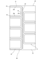
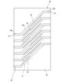
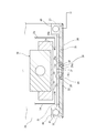
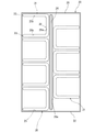
- FIG. 1 is a front sectional view illustratively showing an atmospheric pressure plasma processing apparatus according to a first embodiment of the present invention. It is a bottom view of the processing head of the atmospheric pressure plasma processing apparatus. It is a bottom view of a processing head of an atmospheric pressure plasma processing apparatus, showing a second embodiment of the present invention. It is a bottom view of a processing head of an atmospheric pressure plasma processing apparatus, showing a third embodiment of the present invention. It is a front sectional view of the processing head of the atmospheric pressure plasma processing apparatus, showing a fourth embodiment of the present invention. It is a bottom view of the processing head of the fourth embodiment. It is a bottom view of a processing head of an atmospheric pressure plasma processing apparatus, showing a fifth embodiment of the present invention.
- the plasma processing apparatus 1 includes an object placement unit 2 and a processing head 3.
- the placement unit 2 is composed of a stage, and the workpiece 9 is placed on the upper side.
- the placement unit 2 may be a roller conveyor or a belt conveyor.
- the workpiece 9 is a glass substrate for a flat panel display, for example.
- the workpiece 9 is not limited to a glass substrate, and may be, for example, a continuous sheet-like resin film or a semiconductor substrate.
- the placement unit 2 also serves as a moving unit for the workpiece 9 and can transport the workpiece 9 in the left-right direction in FIG.
- the workpiece 9 is placed in the processing space 1 b below the processing head 3.
- the position of the workpiece 9 may be fixed, and the processing head 3 may move in the left-right direction.
- the processing head 3 is supported by a gantry (not shown) and is located above the placement unit 2.
- the processing head 3 has a housing 3 a, a first electrode 10, and a second electrode 20.
- the first electrode 10 is accommodated in the housing 3a.
- the second electrode 20 is disposed at the bottom of the housing 3a.
- a discharge space 1 a near atmospheric pressure is formed between the first electrode 10 and the second electrode 20.
- a second electrode 20 is interposed between the first electrode 10 and the arrangement part 2.
- the first electrode 10 is made of a metal such as stainless steel or aluminum.
- the first electrode 10 has a thick flat plate shape in which the longitudinal direction is in a direction perpendicular to the paper surface of FIG. 1 and the short side direction is in the left-right direction in FIG.
- the first electrode 10 is connected to the power source 4 and serves as an electric field application electrode.
- the lower surface of the first electrode 10 (the surface facing the arrangement part 2) is a first discharge surface 11.
- a first solid dielectric 13 is provided on the first discharge surface 11.
- the first solid dielectric 13 is composed of a plate made of ceramic such as alumina, and is arranged with the longitudinal direction oriented in a direction perpendicular to the paper surface of FIG.
- a solid dielectric 13 covers the first discharge surface 11.
- a wall 13 w along the side surface of the first electrode 10 is integrally provided at the left and right ends of the solid dielectric 13.
- the first electrode 11 is placed on and supported by the solid dielectric 13.
- the solid dielectric 13 is not limited to a ceramic plate, and may be a sprayed film such as alumina or a resin.
- a cooling path 14 is formed inside the first electrode 10.
- the cooling path 14 extends in the longitudinal direction of the first electrode 10 (the direction orthogonal to the plane of FIG. 1).
- a cooling medium from a cooling medium supply means (not shown) is passed through the cooling path 14.
- water is used as the cooling medium.
- the second electrode 20 is made of a metal having high heat resistance and corrosion resistance such as stainless steel and titanium. As shown in FIGS. 1 and 2, the second electrode 20 has a flat plate shape in which the longitudinal direction is in a direction perpendicular to the paper surface of FIG. 1 and the short direction is in the left-right direction in FIG. 1. The second electrode 20 is disposed below the first electrode 10 in parallel with the first electrode 10. The thickness (vertical dimension) of the second electrode 20 is smaller than the thickness of the first electrode 10.
- the second electrode 20 is electrically grounded via the grounding wire 4e and serves as a ground electrode.
- the upper surface of the second electrode 20 is a second discharge surface 21.
- the second discharge surface 21 faces the first discharge surface 11.
- a processing gas supply path 5 a from the processing gas source 5 extends to the processing head 3.
- the processing gas source 5 stores processing gas corresponding to the processing purpose.
- a fluorine-based gas such as CF 4 or C 2 F 6 is used as a treatment gas component.
- nitrogen, oxygen or the like is used as a treatment gas component.
- the supply path 5a is connected to the left and right sides of the discharge space 1a.
- the supply path 5a is provided with a gas homogenizer for uniformly introducing the processing gas in the longitudinal direction of the discharge space 1a.
- a second solid dielectric 23 is provided on the upper surface of the second discharge surface 21.
- the second solid dielectric 23 is composed of a plate made of ceramic such as alumina, but is not limited thereto, and may be a sprayed film such as alumina or a resin.
- the upper and lower ends of the discharge space 1a are defined by the upper and lower solid dielectrics 13, 23.
- the lower surface of the second electrode 20 is a processing surface 22.
- the processing surface 22 faces the arrangement part 2 and thus the workpiece 9.
- a processing space 1 b is formed between the processing surface 22 and the workpiece 9 on the placement unit 2.
- the processing surface 22 defines the upper end portion of the processing space 1b.
- the second electrode 20 and the solid dielectric 23 are provided with a blowing port 24.
- the blowout port 24 penetrates the solid dielectric 23 in the thickness direction, and further penetrates the second electrode 20 from the second discharge surface 21 to the processing surface 22 in the thickness direction.
- the discharge space 1 a and the processing space 1 b are connected by the blowout port 24.
- the blowout port 24 has a slit shape extending in the longitudinal direction of the second electrode 20 (direction orthogonal to the paper surface of FIG. 1).
- the blowout port 24 is located in the center of the second electrode 20 in the short direction.
- a heat transport means 30 is incorporated in the second electrode 20.
- the heat transport means 30 has higher heat transfer than the second electrode 20, and heat is transferred to the inner side of the second electrode 20 by a temperature difference between the outer peripheral portion of the second electrode 20 and the inner side portion on the inner side in plan view from the outer peripheral portion. Transport from part to outer part.
- the heat transport means 30 includes a plurality of heat transport members 31.
- the heat transport member 31 is configured by a heat pipe.
- the heat pipe 31 has a working fluid sealed inside the pipe body.
- the pipe body of the heat pipe 31 is made of a highly heat conductive metal such as copper or aluminum.
- the heat pipe 31 operates by a temperature difference between the inner part and the outer peripheral part of the second electrode 20. That is, the working fluid undergoes phase change to absorb heat and dissipate heat and move within the pipe body.
- the heat pipe 31 is incorporated in the second electrode 20 as follows. As shown in FIGS. 1 and 2, an accommodation groove 25 is formed on the bottom surface 22 of the second electrode 20. A plurality of receiving grooves 25 are provided at intervals in the longitudinal direction of the second electrode 20, and are arranged on both sides with the blowout port 24 interposed therebetween. The accommodation groove 25 on the left side of the outlet 24 and the accommodation groove 25 on the right side of the outlet 24 are shifted in the longitudinal direction of the second electrode 20 (up and down in FIG. 2).
- Each receiving groove 25 has a central groove portion 25a and a pair of side groove portions 25b, and is U-shaped.
- the central groove portion 25 a is disposed in the vicinity of the blowout port 24, and extends in the longitudinal direction of the second electrode 20 along the blowout port 24.
- Central groove portions 25 a of the plurality of receiving grooves 25 on the left side of the air outlet 24 are arranged in a line along the air outlet 24.
- Central groove portions 25 a of the plurality of receiving grooves 25 on the right side of the air outlet 24 are arranged in a line along the air outlet 24.
- the side groove portion 25 b forms an angle (right angle) with the central groove portion 25 a and extends in the short direction of the second electrode 20.
- a heat pipe 31 is housed in each housing groove 25.
- the heat pipe 31 has a U shape that is the same shape as the housing groove 25.
- a central portion of the heat pipe 31 is accommodated in the central groove portion 25a, and a pair of both side portions intersecting (orthogonal) with the central portion are accommodated in the side groove portion 25b.
- the outer peripheral surface of the heat pipe 31 is in close contact with the inner peripheral surface of the housing groove 25.
- the central portion of the heat pipe 31 is disposed in the vicinity of the blowout port 24 inside the second electrode 20, and extends in the longitudinal direction of the second electrode 20 along the blowout port 24.
- the center portion of the heat pipe 31 is a heat absorbing portion 32.
- the working fluid evaporates in the heat absorbing part 32.
- the heat absorbing portions 32 of the plurality of heat pipes 31 on the left side of the air outlet 24 are arranged in a line along the air outlet 24.
- the heat absorbing portions 32 of the plurality of heat pipes 31 on the right side of the air outlet 24 are arranged in a line along the air outlet 24.
- Both side portions of the heat pipe 31 extend in the short direction of the second electrode 20.
- the ends of the both sides of the heat pipe 31 are located near the outer periphery of the second electrode 20, specifically, the left and right outer edges of the second electrode 20. Yes.
- the tip of the heat pipe 31 is a heat radiating part 33.
- the working fluid is condensed in the heat radiating section 33.
- protrusions 40 are integrally provided so as to protrude upward.
- the ridges 40 extend in the longitudinal direction of the second electrode 20 (direction perpendicular to the paper surface of FIG. 1).
- a cooling path 41 is formed inside each ridge 40.
- the cooling path 41 extends in the longitudinal direction of the second electrode 20 and intersects the heat radiating portion 33 of each heat pipe 31 in plan view.
- a cooling medium from a cooling medium supply means (not shown) is passed through the cooling path 41. For example, water is used as the cooling medium.
- the ridge 40 having the cooling path 41 constitutes a cooling part of the heat radiating part 33.
- the workpiece 9 is set on the placement unit 2 and a voltage is supplied from the power source 4 to the electrode 10. Thereby, an atmospheric pressure glow discharge is generated between the first electrode 10 and the second electrode 20, and the interelectrode space 1a becomes a discharge space. Further, the processing gas is supplied from the processing gas source 5 to the discharge space 1a through the processing gas supply path 5a. As a result, the processing gas is turned into plasma (including decomposition, excitation, activation, radicalization, ionization, etc.). This plasmaized processing gas (hereinafter referred to as “plasma gas” as appropriate) is blown out from the blowout opening 24 and comes into contact with the workpiece 9. As a result, a reaction occurs on the surface of the workpiece 9 and a desired surface treatment is performed. Furthermore, by moving the placement unit 2 relative to the processing head 3, the entire workpiece 9 can be processed.
- the electrodes 10 and 20 and the solid dielectrics 13 and 23 generate heat due to the discharge.
- a coolant such as water is circulated through the cooling path 14.
- the first electrode 10 can be cooled, and the solid dielectric 13 can be further cooled via the first electrode 10.
- the solid dielectric 13 can be prevented from being thermally destroyed.
- the heat of the second electrode 20 can be removed by the heat transport means 30. More specifically, the inner part (mainly the part corresponding to the discharge space 1a) of the second electrode 20 inside the outer peripheral part generates heat due to the discharge. In particular, the peripheral portion of the outlet 24 through which the plasma gas passes out of the inner portion of the second electrode 20 generates heat. The working fluid in the heat absorbing portion 32 absorbs the heat around the blowout port 24 as latent heat, and the working fluid evaporates. As a result, the inner part of the second electrode 20, particularly the peripheral part of the outlet 24 can be cooled. Cooling can prevent thermal deformation of the second electrode 20. As a result, the uniformity of processing can be secured. Further, the solid dielectric 23 can be cooled via the second electrode 20. Thereby, the solid dielectric 23 can be prevented from being thermally destroyed.
- the working fluid evaporated in the heat absorbing portion 32 flows toward the heat radiating portion 33 due to a temperature gradient in the extending direction of the heat pipe 31. That is, the heat absorbed by the working fluid as latent heat at the inner side of the second electrode 20 is transported in the extending direction of the heat pipe 31.
- the outer peripheral portion of the second electrode 20 where the heat radiating portion 33 is present is at a lower temperature than the inner portion of the second electrode 20.
- the working fluid releases heat at the heat radiating portion 33 and condenses.
- the condensed working fluid travels through the wick (capillary structure) of the heat pipe 31 by a capillary phenomenon and moves to the heat absorbing section 32.
- Cooling water is passed through the cooling path 41 of the cooling unit 40.
- the left and right ends of the second electrode 20 are cooled by the cooling water.
- the heat radiation part 33 of each heat pipe 31 can be cooled.
- the thermal radiation efficiency in the thermal radiation part 33 can be improved.
- the heat absorption efficiency in the heat absorption part 32 can be improved.
- the cooling efficiency of the inner part of the second electrode 20 can be increased, the thermal deformation of the second electrode 20 can be reliably prevented, and the processing uniformity can be sufficiently ensured.
- the solid dielectric 23 can be sufficiently cooled via the second electrode 20, and the thermal breakdown of the solid dielectric 23 can be more reliably prevented.
- the apparent heat conductivity (heat conductivity) of the heat pipe 31 is sufficiently larger than the metal (stainless steel or titanium) constituting the second electrode 20, and has a large heat transport capability with a small cross-sectional area. Therefore, the thickness of the second electrode 20 can be made sufficiently smaller than the formation of a refrigerant path through which a refrigerant such as water flows in the second electrode 20, and the distance between the discharge space 1 a and the workpiece 9 can be sufficiently increased. Can be shortened. Therefore, the distance until the plasma-ized processing gas reaches the workpiece 9 from the discharge space 1a can be sufficiently shortened, and the workpiece 9 can be reliably reached before the processing gas is deactivated. As a result, the processing efficiency can be increased.
- Each heat pipe 31 can be shortened by arranging a plurality of heat pipes 31 in the longitudinal direction of the second electrode 20. Thereby, heat transport efficiency can be maintained high. At the same time, the second electrode 20 can be made longer, and further, the workpiece 9 can be made wider and larger, and the processing uniformity can be ensured.
- the peripheral portion of the slit-like air outlet 24 can be reliably cooled. As a result, sufficient uniformity of processing can be secured. Furthermore, the thermal breakdown of the solid dielectric 23 can be more reliably prevented. Since the left heat pipe 31 and the right heat pipe 31 are displaced in the longitudinal direction of the second electrode 20 across the blowout port 24, it is possible to prevent the heat of plasma from being accumulated.
- the shape, extending direction, number, and the like of the outlets 24 can be arbitrarily set.
- the shape, the extending direction, the number, the arrangement, and the like of the heat pipe 31 can be appropriately changed according to the shape, the extending direction, the number, and the like of the blowout port 24.
- the second electrode 20 is provided with a plurality (five in the figure) of blowout ports 24.
- Each outlet 24 is inclined with respect to the longitudinal direction of the second electrode 20.
- a plurality of outlets 24 are arranged in parallel to each other at intervals in the longitudinal direction of the second electrode 20.
- the number of heat pipes 31 in the second embodiment is one more than the number of outlets 24.
- the heat pipes 31 are arranged alternately with the air outlets 24 between the adjacent air outlets 24 and further outside the outermost air outlet 24.
- the plurality of heat pipes 31 are arranged in parallel to each other at intervals in the longitudinal direction of the second electrode 20.
- the heat absorption part 32 of each heat pipe 31 is inclined with respect to the longitudinal direction of the second electrode 20 and extends along the outlet 24. Thereby, the peripheral part of each blower outlet 24 of the 2nd electrode 20 can be cooled reliably.
- the heat radiating portion 33 of each heat pipe 31 is connected to both end portions of the heat absorbing portion 32 and extends to the vicinity of the left and right edges of the second electrode 20 along the short direction of the second electrode 20.
- the second electrode 20 and the blowout port 24s of the solid dielectric 23 are small holes.
- a plurality of outlets 24 s are arranged in a line obliquely with respect to the longitudinal direction of the second electrode 20 to constitute a small hole-like outlet row 24 ⁇ / b> L.
- a plurality of outlet rows 24 ⁇ / b> L are arranged in the longitudinal direction of the second electrode 20.
- the heat pipes 31 are arranged so as to alternate with the outlet array 24L.
- the heat absorbing portion 32 of the heat pipe 31 is inclined with respect to the longitudinal direction of the second electrode 20 and extends along each outlet row 24L.
- the heat radiating part 33 of the heat pipe 31 is connected to the end of the heat absorbing part 32 at an angle and extends in the short direction of the second electrode 20 to the vicinity of the left and right edges.
- the processing plate 22 of the second electrode 20 is covered with a cover plate 29.
- a cover plate 29 closes the opening of the accommodation groove 25 on the processing surface 22 side and covers the heat pipe 31.
- the cover plate 29 is preferably made of a material having excellent corrosion resistance such as stainless steel.
- the cover plate 29 is formed with a blowing communication port 29 a that communicates with the blowing port 24.
- the width of the communication port 29 a is larger than the width of the blowout port 24, but may be the same width as the blowout port 24 or smaller than the width of the blowout port 24.
- the cover plate 29 is joined to the second electrode 20 by welding. Welding is performed over the entire circumference of the outer peripheral edge of the cover plate 29. Further, the periphery of the blowout communication port 29a is also welded over the entire periphery. Thereby, generation
- the thickness of the cover plate 29 is preferably as small as possible from the viewpoint of ensuring the processing efficiency by shortening the distance between the discharge space 1a and the workpiece 9 and is preferably of a size that can be easily welded.
- the thickness of the cover plate 29 in consideration of processing efficiency and weldability is preferably about 0.1 to 1 mm.
- the joining means between the cover plate 29 and the second electrode 20 may use bolts instead of welding.
- the cover plate 29 is applied to the first embodiment, but in the fifth embodiment shown in FIG. 7, the second embodiment of the third embodiment (FIG. 4) is used.
- a cover plate 29 covers the processing surface 22 of the electrode 20.
- a plurality of blowing communication ports 29a are formed in the cover plate 29 of FIG. Each blowout communication port 29a is inclined with respect to the longitudinal direction and extends in parallel with the blowout row 24L.
- a plurality of blowing communication ports 29a are arranged in parallel to each other.
- One blowing port row 24L is connected to each blowing communication port 29a.
- the accommodation groove of the heat transport means 30 is a through accommodation groove 25 ⁇ / b> C penetrating from the second discharge surface 21 to the treatment surface 22.
- the heat pipe 31 is accommodated in the through-accommodating groove 25C.
- a cover plate 28 covers the second discharge surface 21.
- the cover plate 28 closes the opening on the second discharge surface 21 side of the through-accommodating groove 25C and covers the heat pipe 31 from the second discharge surface 21 side.
- the cover plate 28 is preferably made of metal, and more preferably made of the same material (stainless steel or titanium) as the second electrode 20.
- the cover plate 28 is in close contact with the second electrode 20 by joining means (not shown) such as bolting or welding.
- the second electrode 20 and the cover plate 28 are electrically connected.
- a cover plate 28 is provided as part of the second electrode 20.
- the joining means of the cover plate 28 and the second electrode 20 is preferably arranged so as not to face the discharge space 1a.
- the plasma electric field is applied between the first discharge surface 11 and the upper surface of the cover plate 28.
- the cover plate 27 has a thin plate shape corresponding to the shape of the through-accommodating groove 25C.
- the cover plate 27 is fitted into a portion on the second discharge surface 21 side inside the through-accommodating groove 25C.
- the cover plate 27 closes the opening on the second discharge surface 21 side of the through-accommodating groove 25C, and covers the heat pipe 31 from the second discharge surface 21 side.
- the upper surface of the cover plate 27 is flush with the second discharge surface 21.
- FIG. 10 shows an eighth embodiment of the present invention.
- a bottomed (non-penetrating) housing groove 25 is formed in the second discharge surface 21 of the second electrode 20, and the heat pipe 31 is housed in the housing groove 25.
- the housing groove 25 Similar to the first embodiment (FIGS. 1 and 2), the housing groove 25 has a central groove portion 25a along the outlet 24 and a side groove portion 25b orthogonal to the central groove portion 25a.
- a portion in the central groove portion 25 a becomes the heat absorbing portion 32
- a portion on the tip end side (near the outer edge of the second electrode 20) in the side groove portion 25 b becomes the heat radiating portion 33.
- the cover plate 28 covers the second discharge surface 21 as in the sixth embodiment (FIG. 8).
- the cover plate 28 closes the opening on the second discharge surface 21 side of the housing groove 25 and covers the heat pipe 31 from the second discharge surface 21 side.
- the cover plate 28 has substantially the same area as the second electrode 20 and covers almost the entire second discharge surface 21.
- the cover plate 28 is preferably made of metal, and is brought into close contact with the second electrode 20 by a joining means (not shown) such as bolting or welding so as to be electrically connected to the second electrode 20. The point that an electric field is applied between 11 and the cover plate 28 is the same as in the sixth embodiment.
- the cooling unit 40A of the eighth embodiment is configured by a metal member separate from the second electrode 20.
- the cooling part 40A extends in the longitudinal direction of the second electrode 20 (the direction orthogonal to the paper surface of FIG. 10), and the cooling path 41 is formed inside the cooling part 40A. This is the same as the unit 40.
- the left and right ends of the cover plate 28 are sandwiched between the cooling unit 40 ⁇ / b> A and the second electrode 20.
- the cooling unit 40A is in close contact with the cover plate 28.
- the heat radiating part 33 is cooled by the cooling part 40 ⁇ / b> A through the cover plate 28.
- FIG. 11 shows a ninth embodiment.
- the ninth embodiment relates to a modification of the cooling structure of the heat radiating unit 33.
- the housing groove 25 of this embodiment reaches the outer end surface of the second electrode 20 and opens.
- the heat pipe 31 protrudes outward from the outer end surface of the second electrode 20 through the opening of the housing groove 25 and is bent upward.
- the protruding end portion of the heat pipe 31 is a heat radiating portion 33.
- the heat radiation part 33 is provided with heat radiation fins 42 as cooling parts.
- the heat radiating fins 42 may be made of copper or aluminum integral with the heat pipe 31, may be made of a metal separate from the heat pipe 31, and may be connected to the outer periphery of the heat pipe 31.
- the heat of the heat radiating part 33 is transmitted to the heat radiating fins 42 and is dissipated from the heat radiating fins 42. Thereby, the thermal radiation efficiency of the thermal radiation part 33 can be improved. As a result, the heat absorption efficiency in the heat absorption part 32 can be improved. Therefore, the inside part of the 2nd electrode 20 can fully be cooled, and the uniformity of processing can be secured sufficiently. Since the heat transport efficiency of the heat pipe 31 can be increased, the heat pipe 31 can be made thinner, and consequently the thickness of the second electrode 20 can be made smaller. As a result, the distance between the discharge space 1a and the workpiece 9 can be further shortened, and the processing efficiency can be further increased. Furthermore, the solid dielectric 23 can be sufficiently cooled via the second electrode 20, and thermal destruction of the solid dielectric 23 can be reliably prevented.
- the cooling section 40 ⁇ / b> X of the heat radiating section 33 further includes a blowing means 43 in addition to the heat radiating fins 42.
- the air blowing means 43 is composed of a fan or the like. The wind from the blowing means 43 hits the heat radiating fins 42. Thereby, the heat radiation efficiency of the radiation fin 42 can be improved. As a result, the heat dissipation efficiency of the heat dissipation part 33 can be further increased. Therefore, the heat absorption efficiency in the heat absorption part 32 can be further improved. Therefore, the inner part of the second electrode 20 can be further sufficiently cooled, and the uniformity of processing can be ensured reliably.
- the heat transport efficiency of the heat pipe 31 can be further increased, the heat pipe 31 can be further thinned, and the thickness of the second electrode 20 can be further reduced. As a result, the distance between the discharge space 1a and the workpiece 9 can be sufficiently shortened, and the processing efficiency can be further enhanced. Furthermore, the solid dielectric 23 can be more sufficiently cooled via the second electrode 20, and the thermal breakdown of the solid dielectric 23 can be more reliably prevented.
- the heat transport means 30 is higher in heat transfer than the second electrode 20 and transports heat from the inner side to the outer side of the second electrode due to a temperature difference between the inner side and the outer side of the second electrode 20. If it is.
- a metal member having higher thermal conductivity than the second electrode 20 may be used instead of the heat pipe.
- the material of the metal member is preferably a good heat conducting metal such as copper or aluminum.
- the metal member may be rod-shaped or linear, or may be plate-shaped.
- the metal member preferably extends from the inner part of the second electrode 20 to the outer peripheral part.
- One second electrode 20 may be provided with both a heat pipe and the metal member as the heat transport means 30.
- the heat transport means 30 may not necessarily have a portion along the outlet 24.
- the central portion 32 of the heat transport member 31 does not necessarily have to follow the blowout port 24.
- the end 33 of the heat transport member 31 may protrude outward from the outer end of the second electrode 20 regardless of the presence or absence of the radiation fins 42 (FIGS. 11 and 12).
- the cooling unit 40 (FIG. 1) having the cooling path 41 may be a separate member from the second electrode 20.
- the cooling unit 40 which is a separate member from the second electrode 20, may be in close contact with the outer periphery of the second electrode 20, or may be in direct contact with the end of the heat transport member 31.
- the extending direction of the slit-shaped outlet 24 (FIGS. 2 and 3) may be the short direction of the second electrode 20.
- two or more heat transport members 31 may be provided between two adjacent slit-shaped outlets 24, 24.
- the row direction of the small hole-shaped outlets 24 (FIGS. 4 and 7) may be the longitudinal direction of the second electrode 20 or the short direction.
- two or more heat transport members 31 may be provided between two adjacent rows of small hole outlets.
- a plurality of embodiments may be combined.
- a cover plate 29 similar to that of the fifth embodiment (FIG. 7) may be provided on the processing surface 22 of the second electrode 20 of the second embodiment (FIG. 3).
- a thin plate similar to the seventh embodiment (FIG. 9) is used instead of the cover plate 29 that covers substantially the entire processing surface 22 of the second electrode 20.
- the cover plate 27 may be fitted into the housing groove 25 from the lower side (the processing space 1b side).
- a cover plate 29 may be provided on the processing surface 22 of the second electrode 20, and the second electrode 20 may be sandwiched between the cover plate 28 and the cover plate 29.
- a cover plate 29 may be provided on the processing surface 22 of the second electrode 20 in the seventh embodiment (FIG. 9).
- a cover plate 29 instead of the cover plate 28 that covers substantially the entire second discharge surface 21, a thin plate-like cover that fits only in the receiving groove 25, as in the seventh embodiment (FIG. 9).
- the heat pipe 30 may be covered with the plate 27.
- the cover plate structure of the fourth to seventh embodiments (FIGS. 5 to 9) and the heat dissipation structure of the ninth to tenth embodiments (FIGS. 11 and 12) may be combined.
- the means for joining the cover plates 27, 28, 29 to the second electrode 20 is not limited to bolts or welding, and hooks may be used.
- the present invention can be applied to various surface treatments such as surface modification (hydrophilization, water repellency, etc.), ashing, cleaning, etching, and film formation.
- the present invention is not limited to plasma processing near atmospheric pressure, and can also be applied to plasma processing under vacuum.
- the present invention can be applied to a surface treatment in a manufacturing process of a glass substrate for a flat panel display or a semiconductor substrate, for example.
Landscapes
- Physics & Mathematics (AREA)
- Engineering & Computer Science (AREA)
- Plasma & Fusion (AREA)
- Chemical & Material Sciences (AREA)
- Analytical Chemistry (AREA)
- Spectroscopy & Molecular Physics (AREA)
- Plasma Technology (AREA)
- Drying Of Semiconductors (AREA)
Abstract
Description
本発明は、上記事情に鑑み、プラズマ処理装置の電極を厚くすることなく冷却し、処理効率を良好にすることを目的とする。
第1放電面を有し、電源に接続された第1電極と、
前記第1放電面との間に前記放電空間を形成する第2放電面と、前記第2放電面とは反対側の前記処理空間を向く処理面と、前記第2放電面から処理面に貫通する吹き出し口とを有し、電気的に接地された第2電極と、
前記第2電極に設けられ、前記第2電極より伝熱性が高く、前記第2電極の内側部と外周部との間の温度差によって熱を前記第2電極の内側部から外周部に輸送する熱輸送手段と、
を備えたことを特徴とする。
前記第1放電面には、第1固体誘電体が設けられていることが好ましい。前記第2放電面には、第2固体誘電体が設けられていることが好ましい。第1固体誘電体と第2固体誘電体は、少なくとも何れか一方があればよい。前記第2電極の内側部は、第2電極のうち前記放電空間を形成する部分であることが好ましい。前記第2電極の内側部は、前記吹き出し口の周辺部を含むことがより好ましい。前記第2電極の外周部は、第2電極の前記放電空間を形成する部分より外側の部分であることが好ましい。
これによって、第2電極の内側部の温度を確実に下げることができ、第2電極の熱変形をより確実に防止できる。更に、第2電極に第2固体誘電体が設けられている場合、該第2固体誘電体が熱で破損するのを確実に防止できる。また、ヒートパイプは、小さな断面積で大きな吸熱能力及び熱輸送能力を有するから、第2電極の厚さが増大するのを確実に回避でき、或いは第2電極の厚さを小さくできる。したがって、プラズマ化された処理ガスが失活しないうちに被処理物により確実に到達でき、処理効率を高めることができる。
前記吸熱部が、前記吹き出し口の近傍に配置されていることがより好ましい。これによって、第2電極の内側部のうち特に高温化しやすい吹き出し口の周辺部の温度を下げることができる。
前記放熱部は、第2電極の前記放電空間を形成する部分より外側の部分に配置されていることが好ましい。前記放熱部は、第2電極の外周部内に位置していてもよく、第2電極より外側に突出していてもよい。
ここで、第2電極の材質は、耐蝕性の観点からステンレス、チタン等の金属であることが好ましい。
前記金属性熱輸送部材の熱伝導率は第2電極の熱伝導率より高いのが好ましい。この場合、前記金属性熱輸送部材の熱伝導率は200W/(m・K)以上が好ましく、さらに300W/(m・K)以上が好ましい。この条件を満たす金属としては、アルミニウム、金、銅、銀などが挙げられ、特に銅、アルミニウムが好ましい。
複数の熱輸送部材によって、第2電極の温度を十分に下げることができ、第2電極の熱変形を十分に防止又は抑制できる。したがって、処理の均一性を十分に確保できる。さらには、処理効率を確実に高めることができる。また、第2電極に第2固体誘電体が設けられている場合、該第2固体誘電体が熱で破損するのを確実に防止できる。
ガラス基板やフィルム等の被処理物は、近年、広幅化、大型化が進んでおり、これに伴い電極の長尺化が進んでいる。これに対し、1つの熱輸送部材を長くすると熱輸送効率が低下するおそれがある。複数の熱輸送部材を第2電極の長手方向に並べることで、電極の長尺化に対応でき、かつ各熱輸送部材を短くでき、熱輸送効率を高く維持できる。
複数のヒートパイプによって、第2電極を十分に冷却できる。これにより、第2電極の熱変形を確実に防止でき、処理の均一性を十分確保でき、かつ処理効率を高めることができる。また、第2電極に第2固体誘電体が設けられている場合、該第2固体誘電体が熱で破損するのを一層確実に防止できる。
これによって、吹き出し口の周辺部を確実に冷却できる。
吹き出し口が、スリット状になり、第2電極の長手方向に延びている場合、或いは、吹き出し口が多数の小孔状であり、第2電極の長手方向に小孔状の吹き出し口が一列に並んでいる場合、複数のヒートパイプの吸熱部が、吹き出し口に沿うように第2電極の長手方向に並べられていることが好ましい。
複数の吹き出し口が、第2電極の長手方向に並べられ、各吹き出し口が第2電極の長手方向と交差する方向に延びるスリット状である場合、各ヒートパイプが一部の吹き出し口に対応するよう第2電極の長手方向に並べられ、各ヒートパイプの吸熱部が、対応する吹き出し口に沿っていることが好ましい。
吹き出し口が多数の小孔状であり、第2電極の長手方向と交差する方向に小孔状の吹き出し口が一列に並べられ、かつ前記小孔状吹き出し口の列が第2電極の長手方向に並べられている場合、各ヒートパイプが1又は複数の小孔状吹き出し口の列に対応するよう第2電極の長手方向に並べられ、各ヒートパイプの吸熱部が、対応する小孔状吹き出し口の列に沿っていることが好ましい。
第2電極の外周部を冷却することで、第2電極の内側部と外周部の温度差が大きくなる。したがって、熱輸送手段による熱の輸送を促進できる。これにより、第2電極の内側部の温度を確実に下げることができ、処理の均一性をより確実に維持でき、処理効率を確実に向上できる。第2電極に第2固体誘電体が設けられている場合、該第2固体誘電体の熱破壊を一層確実に防止できる。
これによって、放熱部の放熱を促進できる。ひいては、吸熱部の吸熱を促進できる。この結果、第2電極の内側部の冷却効率を高めることができ、処理の均一性をより確実に維持でき、処理効率を確実に向上できる。第2電極に第2固体誘電体が設けられている場合、該第2固体誘電体の熱破壊を一層確実に防止できる。
これによって、第2電極の外周部又は放熱部の熱を冷却路内の冷媒に移して放出でき、第2電極の外周部又は放熱部の放熱効率を高めることができる。冷却路は、第2電極の外周部に形成されていてもよく、第2電極とは別の冷却路形成部材に形成されていてもよい。第2電極とは別の冷却路形成部材は、第2電極の外周部に接していてもよい。熱輸送部材の端部又は放熱部が第2電極から突出し、この突出部分に第2電極とは別の冷却路形成部材が接していてもよい。
放熱部の熱が放熱フィンに伝わり、放熱フィンから放散される。これにより、放熱部の放熱効率を高めることができる。
これによって、放熱フィンからの放熱効率を高めることができ、ひいては放熱部の放熱効率を一層高めることができる。
これによって、熱輸送手段が第2放電面又は処理面から突出するのを防止できる。収容溝は、第2放電面に形成されていてもよく、処理面に形成されていてもよい。
これによって、熱輸送手段がプラズマや処理ガスで腐食するのを防止できる。
これによって、熱輸送手段がプラズマや処理ガスで腐食するのを防止できる。覆板の表面を平滑にすることで第2放電面又は処理面の平滑性を確保できる。
前記覆板は、第2放電面又は処理面の全体を覆っていてもよく、第2放電面又は処理面の収容溝を含む一部を覆っていてもよい。
前記覆板が、収容溝のみを覆っていてもよい。
図1に示すように、プラズマ処理装置1は、被処理物配置部2と、処理ヘッド3を備えている。配置部2は、ステージで構成されており、その上側に被処理物9が配置される。配置部2は、ローラコンベアやベルトコンベアでもよい。被処理物9は、例えばフラットパネルディスプレイ用のガラス基板である。被処理物9は、ガラス基板に限られず、例えば連続シート状の樹脂フィルムでもよく、半導体基板でもよい。
被処理物9が位置固定され、処理ヘッド3が左右方向に移動するようになっていてもよい。
第1電極10は、ステンレスやアルミニウム等の金属で構成されている。第1電極10は、長手方向を図1の紙面と直交する方向に向け、短手方向を図1の左右方向に向けた厚い平板状になっている。第1電極10は、電源4に接続され、電界印加電極になっている。第1電極10の下面(配置部2を向く面)は、第1放電面11になっている。第1放電面11に第1固体誘電体13が設けられている。第1固体誘電体13は、アルミナ等のセラミックからなる板で構成され、長手方向を図1の紙面と直交する方向に向け、短手方向を図1の左右方向に向けて配置されている。固体誘電体13が第1放電面11を覆っている。固体誘電体13の左右の端部には、第1電極10の側面に沿う壁13wが一体に設けられている。第1電極11が、固体誘電体13に載せられ、支持されている。固体誘電体13は、セラミック板に限られず、アルミナ等の溶射膜でもよく、樹脂でもよい。
図1及び図2に示すように、第2電極20の底面22には、収容溝25が形成されている。収容溝25は、第2電極20の長手方向に間隔を置いて複数設けられ、かつ吹き出し口24を挟んで両側に配置されている。吹き出し口24の左側の収容溝25と吹き出し口24の右側の収容溝25とは、第2電極20の長手方向(図2において上下)にずれている。
吹き出し口24の形状、延び方向、数などは、任意に設定できる。ヒートパイプ31の形状、延び方向、数、配置等は、吹き出し口24の形状、延び方向、数等に応じて適宜変更できる。
図3に示す第2実施形態では、第2電極20に複数(図では5つ)の吹き出し口24が設けられている。各吹き出し口24は、第2電極20の長手方向に対し斜めになっている。複数の吹き出し口24が第2電極20の長手方向に間隔を置いて互いに平行に並んでいる。
この実施形態の収容溝25は、第2電極20の外端面に達して開口している。この収容溝25の開口を介して、ヒートパイプ31が、第2電極20の外端面より外側に突出され、上へ向けて折曲されている。このヒートパイプ31の突出端部が、放熱部33になっている。放熱部33に冷却部として放熱フィン42が設けられている。放熱フィン42は、ヒートパイプ31と一体の銅やアルミで構成されていてもよく、ヒートパイプ31とは別体の金属で構成され、ヒートパイプ31の外周に連結されていてもよい。
例えば、熱輸送手段30は、第2電極20より伝熱性が高く、第2電極20の内側部と外周部との間の温度差によって熱を第2電極の内側部から外周部に輸送するものであればよい。熱輸送部材31として、ヒートパイプに代えて第2電極20より熱伝導率が高い金属部材を用いてもよい。金属部材の材質は、銅、アルミニウム等の良熱伝導金属であることが好ましい。金属部材は、棒状ないしは線状になっていてもよく、板状になっていてもよい。金属部材は、第2電極20の内側部から外周部に延びていることが好ましい。
1つの第2電極20に、熱輸送手段30としてヒートパイプと上記金属部材の両方を設けてもよい。
熱輸送手段30が、吹き出し口24に沿う部分を必ずしも有していなくてもよい。熱輸送部材31の中央部32が、吹き出し口24に必ずしも沿っていなくてもよい。
熱輸送部材31の端部33が、放熱フィン42(図11、図12)の有無に拘らず、第2電極20の外端部から外側に突出していてもよい。
スリット状吹き出し口24(図2、図3)の延び方向は、第2電極20の短手方向でもよい。スリット状吹き出し口24が複数有る場合(図3)、隣り合う2つのスリット状吹き出し口24,24の間に2以上の熱輸送部材31が設けられていてもよい。
小孔状吹き出し口24(図4、図7)の列の並び方向は、第2電極20の長手方向でもよく、短手方向でもよい。小孔状吹き出し口24の列が複数有る場合(図4、図7)、隣り合う2つの小孔状吹き出し口の列どうしの間に2以上の熱輸送部材31が設けられていてもよい。
第4、第5実施形態(図5~図7)において、第2電極20の処理面22の略全体を覆う覆板29に代えて、第7実施形態(図9)と同様の細板状の覆板27を下側(処理空間1bの側)から収容溝25の内部に嵌め込んでもよい。
第6実施形態(図8)において、第2電極20の処理面22に覆板29を設け、覆板28と覆板29で第2電極20を挟んでもよい。同様に、第7実施形態(図9)において、第2電極20の処理面22に覆板29を設けてもよい。第8実施形態(図10)において、第2放電面21のほぼ全体を覆う覆板28に代えて、第7実施形態(図9)と同様に、収容溝25だけに嵌る細板状の覆板27にてヒートパイプ30を覆ってもよい。
第4~第7実施形態(図5~図9)の覆板構造と第9~第10実施形態(図11、図12)の放熱構造とを組み合わせてもよい。
覆板27,28,29の第2電極20への接合手段は、ボルトや溶接に限られず、フックを用いてもよい。
1a 放電空間
1b 処理空間
2 配置部
3 処理ヘッド
3a 筐体
4 電源
4e 接地線
5 処理ガス源
5a 処理ガス供給路
9 被処理物
10 第1電極
11 第1放電面
13 第1固体誘電体
13w 側壁
14 冷却路
20 第2電極
21 第2放電面
22 処理面
23 第2固体誘電体
24 スリット状吹き出し口
24s 小孔状吹出し口
24L 小孔状吹出し口列
25 収容溝
25a 中央溝部分
25b 側溝部分
25C 貫通収容溝
27,28,29 覆板
29a 吹き出し連通口
30 熱輸送手段
31 ヒートパイプ(熱輸送部材)
32 吸熱部
33 放熱部
40,40A,40X 冷却部
41 冷却路
42 放熱フィン
43 送風手段
Claims (15)
- 処理ガスを放電空間でプラズマ化して吹き出し、前記放電空間の外部の処理空間に配置された被処理物に接触させ、プラズマ表面処理を行なう装置において、
第1放電面を有し、電源に接続された第1電極と、
前記第1放電面との間に前記放電空間を形成する第2放電面と、前記第2放電面とは反対側の前記処理空間を向く処理面と、前記第2放電面から処理面に貫通する吹き出し口とを有し、電気的に接地された第2電極と、
前記第2電極に設けられ、前記第2電極より伝熱性が高く、前記第2電極の内側部と外周部との間の温度差によって熱を前記第2電極の内側部から外周部に輸送する熱輸送手段と、
を備えたことを特徴とするプラズマ処理装置。 - 前記熱輸送手段が、作動流体を蒸発させて吸熱する吸熱部と、前記作動流体を凝縮させて放熱する放熱部とを有するヒートパイプを含み、前記吸熱部が、前記第2電極の内側部に設けられ、前記放熱部が、前記第2電極の外周部又は前記第2電極より外側に設けられていることを特徴とする請求項1に記載のプラズマ処理装置。
- 前記吸熱部が、前記吹き出し口の近傍に配置されていることを特徴とする請求項2に記載のプラズマ処理装置。
- 前記熱輸送手段が、複数の熱輸送部材を含み、各熱輸送部材が、前記第2電極より伝熱性が高く、前記第2電極の内側部から前記第2電極の外周部へ延び、該延び方向の温度勾配によって熱を輸送することを特徴とする請求項1に記載のプラズマ処理装置。
- 前記複数の熱輸送部材が、前記第2電極の前記第2放電面又は放電面に沿う長手方向に並んでいることを特徴とする請求項4に記載のプラズマ処理装置。
- 前記各熱輸送部材が、作動流体を蒸発させて吸熱する吸熱部と、前記作動流体を凝縮させて放熱する放熱部とを有するヒートパイプであり、前記吸熱部が、前記第2電極の内側部に設けられ、前記放熱部が、前記第2電極の外周部又は前記第2電極より外側に設けられていることを特徴とする請求項4又は5に記載のプラズマ処理装置。
- 前記複数のヒートパイプが、前記第2電極の前記第2放電面又は放電面に沿う長手方向に並び、各ヒートパイプの吸熱部が、前記吹き出し口に沿っていることを特徴とする請求項6に記載のプラズマ処理装置。
- 前記第2電極の外周部を冷却する冷却部を、更に備えたことを特徴とする請求項1~7の何れか1項に記載のプラズマ処理装置。
- 前記放熱部を冷却する冷却部を、更に備えたことを特徴とする請求項2、3、6、7の何れか1項に記載のプラズマ処理装置。
- 前記冷却部が、冷媒を通す冷却路を含むことを特徴とする請求項8又は9に記載のプラズマ処理装置。
- 前記冷却部が、前記放熱部に設けられた放熱フィンを含むことを特徴とする請求項9に記載のプラズマ処理装置。
- 前記冷却部が、前記放熱フィンに送風する送風手段を含むことを特徴とする請求項11に記載のプラズマ処理装置。
- 前記第2放電面又は処理面に収容溝が形成され、前記熱輸送手段が前記収容溝に収容されていることを特徴とする請求項1~12の何れか1項に記載のプラズマ処理装置。
- 前記収容溝の前記第2放電面又は処理面への開口が、覆板で塞がれていることを特徴とする請求項13に記載のプラズマ処理装置。
- 前記覆板が、前記第2放電面又は処理面を覆っていることを特徴とする請求項14に記載のプラズマ処理装置。
Priority Applications (3)
| Application Number | Priority Date | Filing Date | Title |
|---|---|---|---|
| CN2009801433017A CN102197713A (zh) | 2008-10-29 | 2009-10-26 | 等离子体处理装置 |
| KR1020117012080A KR101271943B1 (ko) | 2008-10-29 | 2009-10-26 | 플라즈마 처리 장치 |
| JP2010535652A JP5406848B2 (ja) | 2008-10-29 | 2009-10-26 | 大気圧プラズマ処理装置 |
Applications Claiming Priority (2)
| Application Number | Priority Date | Filing Date | Title |
|---|---|---|---|
| JP2008277621 | 2008-10-29 | ||
| JP2008-277621 | 2008-10-29 |
Publications (1)
| Publication Number | Publication Date |
|---|---|
| WO2010050169A1 true WO2010050169A1 (ja) | 2010-05-06 |
Family
ID=42128539
Family Applications (1)
| Application Number | Title | Priority Date | Filing Date |
|---|---|---|---|
| PCT/JP2009/005629 Ceased WO2010050169A1 (ja) | 2008-10-29 | 2009-10-26 | プラズマ処理装置 |
Country Status (5)
| Country | Link |
|---|---|
| JP (1) | JP5406848B2 (ja) |
| KR (1) | KR101271943B1 (ja) |
| CN (1) | CN102197713A (ja) |
| TW (1) | TW201031281A (ja) |
| WO (1) | WO2010050169A1 (ja) |
Cited By (3)
| Publication number | Priority date | Publication date | Assignee | Title |
|---|---|---|---|---|
| JP2013129908A (ja) * | 2011-11-22 | 2013-07-04 | Kobe Steel Ltd | プラズマ発生源の冷却機構及び冷却方法 |
| JP2013157101A (ja) * | 2012-01-27 | 2013-08-15 | E Square:Kk | プラズマ表面処理装置 |
| JP2015516662A (ja) * | 2012-05-09 | 2015-06-11 | リンデ アクティエンゲゼルシャフト | プラズマ流を提供するための装置 |
Families Citing this family (3)
| Publication number | Priority date | Publication date | Assignee | Title |
|---|---|---|---|---|
| KR101272101B1 (ko) * | 2011-12-27 | 2013-06-07 | 씨티에스(주) | 상압 플라즈마 헤더 |
| US9224583B2 (en) * | 2013-03-15 | 2015-12-29 | Lam Research Corporation | System and method for heating plasma exposed surfaces |
| DE102017223592B4 (de) | 2017-12-21 | 2023-11-09 | Meyer Burger (Germany) Gmbh | System zur elektrisch entkoppelten, homogenen Temperierung einer Elektrode mittels Wärmeleitrohren sowie Bearbeitungsanlage mit einem solchen System |
Citations (4)
| Publication number | Priority date | Publication date | Assignee | Title |
|---|---|---|---|---|
| JPH01248623A (ja) * | 1988-03-30 | 1989-10-04 | Toshiba Lighting & Technol Corp | 光洗浄装置 |
| JPH0661184A (ja) * | 1992-08-03 | 1994-03-04 | Tokyo Electron Ltd | プラズマ処理装置 |
| JP2001308081A (ja) * | 2000-04-19 | 2001-11-02 | Tokyo Electron Ltd | 熱処理装置及びその方法 |
| JP2004006211A (ja) * | 2001-09-27 | 2004-01-08 | Sekisui Chem Co Ltd | プラズマ処理装置 |
Family Cites Families (2)
| Publication number | Priority date | Publication date | Assignee | Title |
|---|---|---|---|---|
| JP3921234B2 (ja) * | 2002-02-28 | 2007-05-30 | キヤノンアネルバ株式会社 | 表面処理装置及びその製造方法 |
| JP4493932B2 (ja) * | 2003-05-13 | 2010-06-30 | 東京エレクトロン株式会社 | 上部電極及びプラズマ処理装置 |
-
2009
- 2009-10-26 WO PCT/JP2009/005629 patent/WO2010050169A1/ja not_active Ceased
- 2009-10-26 KR KR1020117012080A patent/KR101271943B1/ko active Active
- 2009-10-26 JP JP2010535652A patent/JP5406848B2/ja active Active
- 2009-10-26 CN CN2009801433017A patent/CN102197713A/zh active Pending
- 2009-10-28 TW TW098136559A patent/TW201031281A/zh unknown
Patent Citations (4)
| Publication number | Priority date | Publication date | Assignee | Title |
|---|---|---|---|---|
| JPH01248623A (ja) * | 1988-03-30 | 1989-10-04 | Toshiba Lighting & Technol Corp | 光洗浄装置 |
| JPH0661184A (ja) * | 1992-08-03 | 1994-03-04 | Tokyo Electron Ltd | プラズマ処理装置 |
| JP2001308081A (ja) * | 2000-04-19 | 2001-11-02 | Tokyo Electron Ltd | 熱処理装置及びその方法 |
| JP2004006211A (ja) * | 2001-09-27 | 2004-01-08 | Sekisui Chem Co Ltd | プラズマ処理装置 |
Cited By (3)
| Publication number | Priority date | Publication date | Assignee | Title |
|---|---|---|---|---|
| JP2013129908A (ja) * | 2011-11-22 | 2013-07-04 | Kobe Steel Ltd | プラズマ発生源の冷却機構及び冷却方法 |
| JP2013157101A (ja) * | 2012-01-27 | 2013-08-15 | E Square:Kk | プラズマ表面処理装置 |
| JP2015516662A (ja) * | 2012-05-09 | 2015-06-11 | リンデ アクティエンゲゼルシャフト | プラズマ流を提供するための装置 |
Also Published As
| Publication number | Publication date |
|---|---|
| TW201031281A (en) | 2010-08-16 |
| JPWO2010050169A1 (ja) | 2012-03-29 |
| KR20110077024A (ko) | 2011-07-06 |
| CN102197713A (zh) | 2011-09-21 |
| KR101271943B1 (ko) | 2013-06-07 |
| JP5406848B2 (ja) | 2014-02-05 |
Similar Documents
| Publication | Publication Date | Title |
|---|---|---|
| JP5406848B2 (ja) | 大気圧プラズマ処理装置 | |
| EP2474782B1 (en) | Cooling unit using ionic wind and LED lighting unit including the cooling unit | |
| CN101834120B (zh) | 喷淋头和等离子体处理装置 | |
| WO2011058411A2 (en) | Cooling of electronic components using self-propelled ionic wind | |
| JP6599379B2 (ja) | 放熱装置及びそれを備える光照射装置 | |
| CN111486424B (zh) | 散热装置及具备该散热装置的光照射装置 | |
| JP6165452B2 (ja) | プラズマ処理装置 | |
| JP5725993B2 (ja) | 表面処理装置 | |
| JP4326300B2 (ja) | プラズマcvd装置とプラズマcvd装置用電極 | |
| JP4861387B2 (ja) | プラズマ処理装置 | |
| JP4848493B2 (ja) | プラズマ処理装置 | |
| JP5439018B2 (ja) | 触媒cvd装置 | |
| JP6695192B2 (ja) | プラズマ発生装置 | |
| US10192847B2 (en) | Rapid cooling system for a bond head heater | |
| KR102351319B1 (ko) | 히팅 어셈블리 | |
| JP2007080688A (ja) | プラズマ処理装置の電極構造 | |
| JP2009199740A (ja) | プラズマ処理装置 | |
| JP3858043B2 (ja) | プラズマ処理装置 | |
| JP4451540B2 (ja) | 冷却機能付き光照射式静電気除去装置 | |
| JP2006228658A (ja) | プラズマ処理装置 | |
| JP2008185283A (ja) | ヒートパイプ | |
| JP4495023B2 (ja) | プラズマ処理装置 | |
| KR101072345B1 (ko) | 플라즈마 처리용 수냉식 전극 | |
| JP5148563B2 (ja) | 表面処理装置 | |
| TWI295908B (en) | Plasma discharging device |
Legal Events
| Date | Code | Title | Description |
|---|---|---|---|
| WWE | Wipo information: entry into national phase |
Ref document number: 200980143301.7 Country of ref document: CN |
|
| 121 | Ep: the epo has been informed by wipo that ep was designated in this application |
Ref document number: 09823282 Country of ref document: EP Kind code of ref document: A1 |
|
| WWE | Wipo information: entry into national phase |
Ref document number: 2010535652 Country of ref document: JP |
|
| NENP | Non-entry into the national phase |
Ref country code: DE |
|
| ENP | Entry into the national phase |
Ref document number: 20117012080 Country of ref document: KR Kind code of ref document: A |
|
| 122 | Ep: pct application non-entry in european phase |
Ref document number: 09823282 Country of ref document: EP Kind code of ref document: A1 |