WO2010047097A1 - 車輪用軸受装置 - Google Patents
車輪用軸受装置 Download PDFInfo
- Publication number
- WO2010047097A1 WO2010047097A1 PCT/JP2009/005506 JP2009005506W WO2010047097A1 WO 2010047097 A1 WO2010047097 A1 WO 2010047097A1 JP 2009005506 W JP2009005506 W JP 2009005506W WO 2010047097 A1 WO2010047097 A1 WO 2010047097A1
- Authority
- WO
- WIPO (PCT)
- Prior art keywords
- wheel
- pin
- mounting flange
- brake rotor
- bearing device
- Prior art date
- Legal status (The legal status is an assumption and is not a legal conclusion. Google has not performed a legal analysis and makes no representation as to the accuracy of the status listed.)
- Ceased
Links
Images

Classifications
-
- B—PERFORMING OPERATIONS; TRANSPORTING
- B60—VEHICLES IN GENERAL
- B60B—VEHICLE WHEELS; CASTORS; AXLES FOR WHEELS OR CASTORS; INCREASING WHEEL ADHESION
- B60B27/00—Hubs
-
- F—MECHANICAL ENGINEERING; LIGHTING; HEATING; WEAPONS; BLASTING
- F16—ENGINEERING ELEMENTS AND UNITS; GENERAL MEASURES FOR PRODUCING AND MAINTAINING EFFECTIVE FUNCTIONING OF MACHINES OR INSTALLATIONS; THERMAL INSULATION IN GENERAL
- F16C—SHAFTS; FLEXIBLE SHAFTS; ELEMENTS OR CRANKSHAFT MECHANISMS; ROTARY BODIES OTHER THAN GEARING ELEMENTS; BEARINGS
- F16C19/00—Bearings with rolling contact, for exclusively rotary movement
- F16C19/02—Bearings with rolling contact, for exclusively rotary movement with bearing balls essentially of the same size in one or more circular rows
- F16C19/14—Bearings with rolling contact, for exclusively rotary movement with bearing balls essentially of the same size in one or more circular rows for both radial and axial load
- F16C19/18—Bearings with rolling contact, for exclusively rotary movement with bearing balls essentially of the same size in one or more circular rows for both radial and axial load with two or more rows of balls
- F16C19/181—Bearings with rolling contact, for exclusively rotary movement with bearing balls essentially of the same size in one or more circular rows for both radial and axial load with two or more rows of balls with angular contact
- F16C19/183—Bearings with rolling contact, for exclusively rotary movement with bearing balls essentially of the same size in one or more circular rows for both radial and axial load with two or more rows of balls with angular contact with two rows at opposite angles
- F16C19/184—Bearings with rolling contact, for exclusively rotary movement with bearing balls essentially of the same size in one or more circular rows for both radial and axial load with two or more rows of balls with angular contact with two rows at opposite angles in O-arrangement
- F16C19/186—Bearings with rolling contact, for exclusively rotary movement with bearing balls essentially of the same size in one or more circular rows for both radial and axial load with two or more rows of balls with angular contact with two rows at opposite angles in O-arrangement with three raceways provided integrally on parts other than race rings, e.g. third generation hubs
-
- F—MECHANICAL ENGINEERING; LIGHTING; HEATING; WEAPONS; BLASTING
- F16—ENGINEERING ELEMENTS AND UNITS; GENERAL MEASURES FOR PRODUCING AND MAINTAINING EFFECTIVE FUNCTIONING OF MACHINES OR INSTALLATIONS; THERMAL INSULATION IN GENERAL
- F16C—SHAFTS; FLEXIBLE SHAFTS; ELEMENTS OR CRANKSHAFT MECHANISMS; ROTARY BODIES OTHER THAN GEARING ELEMENTS; BEARINGS
- F16C35/00—Rigid support of bearing units; Housings, e.g. caps, covers
- F16C35/04—Rigid support of bearing units; Housings, e.g. caps, covers in the case of ball or roller bearings
- F16C35/06—Mounting or dismounting of ball or roller bearings; Fixing them onto shaft or in housing
-
- F—MECHANICAL ENGINEERING; LIGHTING; HEATING; WEAPONS; BLASTING
- F16—ENGINEERING ELEMENTS AND UNITS; GENERAL MEASURES FOR PRODUCING AND MAINTAINING EFFECTIVE FUNCTIONING OF MACHINES OR INSTALLATIONS; THERMAL INSULATION IN GENERAL
- F16D—COUPLINGS FOR TRANSMITTING ROTATION; CLUTCHES; BRAKES
- F16D65/00—Parts or details
- F16D65/02—Braking members; Mounting thereof
- F16D65/12—Discs; Drums for disc brakes
-
- F—MECHANICAL ENGINEERING; LIGHTING; HEATING; WEAPONS; BLASTING
- F16—ENGINEERING ELEMENTS AND UNITS; GENERAL MEASURES FOR PRODUCING AND MAINTAINING EFFECTIVE FUNCTIONING OF MACHINES OR INSTALLATIONS; THERMAL INSULATION IN GENERAL
- F16C—SHAFTS; FLEXIBLE SHAFTS; ELEMENTS OR CRANKSHAFT MECHANISMS; ROTARY BODIES OTHER THAN GEARING ELEMENTS; BEARINGS
- F16C2326/00—Articles relating to transporting
- F16C2326/01—Parts of vehicles in general
- F16C2326/02—Wheel hubs or castors
-
- F—MECHANICAL ENGINEERING; LIGHTING; HEATING; WEAPONS; BLASTING
- F16—ENGINEERING ELEMENTS AND UNITS; GENERAL MEASURES FOR PRODUCING AND MAINTAINING EFFECTIVE FUNCTIONING OF MACHINES OR INSTALLATIONS; THERMAL INSULATION IN GENERAL
- F16D—COUPLINGS FOR TRANSMITTING ROTATION; CLUTCHES; BRAKES
- F16D65/00—Parts or details
- F16D65/02—Braking members; Mounting thereof
- F16D2065/13—Parts or details of discs or drums
- F16D2065/134—Connection
- F16D2065/1384—Connection to wheel hub
-
- F—MECHANICAL ENGINEERING; LIGHTING; HEATING; WEAPONS; BLASTING
- F16—ENGINEERING ELEMENTS AND UNITS; GENERAL MEASURES FOR PRODUCING AND MAINTAINING EFFECTIVE FUNCTIONING OF MACHINES OR INSTALLATIONS; THERMAL INSULATION IN GENERAL
- F16D—COUPLINGS FOR TRANSMITTING ROTATION; CLUTCHES; BRAKES
- F16D65/00—Parts or details
- F16D65/02—Braking members; Mounting thereof
- F16D2065/13—Parts or details of discs or drums
- F16D2065/134—Connection
- F16D2065/1392—Connection elements
Definitions
- the present invention relates to a wheel bearing device for supporting a wheel of an automobile or the like, and in particular, for a wheel whose manufacturing efficiency is improved by temporarily fixing a brake rotor to a wheel mounting flange of a hub wheel in a short time.
- the present invention relates to a bearing device.
- a brake rotor is attached to the wheel mounting flange of the hub wheel together with the wheel.
- the mounting of the brake rotor is generally performed by, for example, a car manufacturer at a delivery destination, but the number of cases where the brake rotor is delivered with the brake rotor temporarily fixed is increasing. In this case, the brake rotor was screwed to the wheel mounting flange and delivered.
- This wheel bearing device 50 integrally has a wheel mounting flange 51 for mounting a wheel (not shown) at one end, one inner rolling surface 52a on the outer periphery, and a shaft from the inner rolling surface 52a.
- a small-diameter step portion 52b extending in the direction is formed, a hub wheel 52 having a serration 52c for torque transmission formed on the inner periphery, and the small-diameter step portion 52b of the hub wheel 52 is press-fitted, and the other inner rolling surface is formed on the outer periphery.
- An inner member 54 formed of an inner ring 53 formed with 53a and a vehicle body mounting flange 55b for mounting to a vehicle body (not shown) on the outer periphery are integrally formed, and double row rolling surfaces 55a, 55a are mounted on the inner periphery.
- the outer member 55 is formed with a plurality of balls 57 and 57, which are circumferentially arranged by the cages 56 and 56 and accommodated so as to roll between the rolling surfaces.
- Hub bolts 58 for fixing the wheels are planted at equal circumferential positions of the wheel mounting flanges 51.
- wheel 53 is being fixed to the axial direction by the crimping part 52d formed by carrying out the plastic deformation of the edge part of the small diameter step part 52b to radial direction outward.
- seals 59 and 60 are attached to both ends of the outer member 55 to seal the annular space between the outer member 55 and the inner member 54, and to leak the lubricating grease enclosed in the bearing to the outside. Prevents rainwater and dust from entering the bearing from the outside.
- a through hole 51a is formed in the wheel mounting flange 51 of the hub wheel 52, and a pin 61 as a projecting portion is press-fitted and fixed to the through hole 51a, and an insertion hole 62a is provided in the brake rotor 62 as an insertion portion. ing. And in the state which inserted the front end side of the pin 61 in the insertion hole 62a, the brake rotor 62 will be in the state temporarily fixed to the wheel attachment flange 51, and will not remove
- the pin 61 can be press-fitted into the insertion hole 62a simply by pressing the insertion hole 62a of the brake rotor 62 facing the pin 61, and the wheel in which the brake rotor 62 is temporarily fixed to the wheel mounting flange 51.
- the bearing device 50 can be completed easily in a short time (for example, refer to Patent Document 1).
- this wheel bearing device 50 has the following problems. That is, (1) If the number of temporarily fixing pins 61 does not match the number of hub bolts 58, the rotational balance of the hub wheel 52 may be lost. (2) When the pin 61 is press-fitted into the through hole 51a of the wheel mounting flange 51, the wheel mounting flange 51 is deformed, and the surface runout accuracy of the side surface 51b of the wheel mounting flange 51 that becomes the mounting surface of the brake rotor 62 decreases. There is a risk of triggering brake judder.
- the present invention has been made in view of such circumstances.
- the brake rotor is temporarily fixed to the wheel mounting flange of the hub wheel in a short time to improve the manufacturing efficiency, and the accuracy of the wheel mounting flange is improved.
- An object of the present invention is to provide a wheel bearing device in which the strength of a pin is secured and the reliability is improved.
- the invention according to claim 1 of the present invention includes an outer member in which a double row outer rolling surface is integrally formed on the inner periphery, and an outer rolling of the double row on the outer periphery.
- a cylindrical pilot portion that guides and supports the brake rotor is formed, and a plurality of hub bolts are press-fitted in the circumferential direction of the wheel mounting flange.
- a through hole is formed and a chamfered portion is formed at the end.
- the formed hollow pin is press-fitted and fixed in the through hole, and a through hole and an insertion hole are provided at positions corresponding to the hub bolt and the pin of the brake rotor, respectively, and the distal end side of the pin is located in the insertion hole. Inserted or press-fitted, the brake rotor is temporarily fixed to the wheel mounting flange.
- a hollow pin with a through-hole formed in the wheel mounting flange and a chamfered portion at the end is press-fitted into the through-hole, and penetrates into the position corresponding to the hub bolt and pin of the brake rotor.
- a hole and an insertion hole are provided, and the tip end side of the pin is inserted or press-fitted into the insertion hole, and the brake rotor is temporarily fixed to the wheel mounting flange, so that the through hole of the brake rotor faces the hub bolt and is inserted as it is.
- the brake rotor is held in a state of being prevented from rotating with respect to the wheel mounting flange, and the pin can be easily inserted or press-fitted into the insertion hole in a short time by the chamfered portion of the pin. It will not come off the mounting flange. Moreover, since the pin is formed in a hollow shape, pressure input can be suppressed, deformation of the wheel mounting flange during press-fitting can be prevented, and surface runout accuracy of the wheel mounting flange can be ensured.
- a chamfered portion is formed in the insertion hole of the brake rotor, and the distance from the side surface on the outer side of the wheel mounting flange to the chamfered portion of the pin is larger than the dimension of the chamfered portion. If the dimensions are set to be large, even if shear force from the brake rotor is applied to the pin, it can be supported by the cylindrical surface of the pin, and it is possible to prevent generation of component force that lifts the brake rotor.
- the brake rotor can be temporarily fixed stably without falling off.
- the pin is constituted by a spring pin having a slit extending in the axial direction, the deformation of the wheel mounting flange at the time of press-fitting is prevented, and the insertion hole of the brake rotor is prevented.
- the pin may be formed of a pipe material.
- the pin may be formed of stainless steel.
- the surface of the pin may be subjected to a phosphate coating treatment.
- the wheel bearing device includes an outer member in which a double row outer rolling surface is integrally formed on an inner periphery, and a double row inner rolling that faces the outer rolling surface of the double row on an outer periphery.
- a wheel mounting flange for mounting a wheel via a brake rotor is integrally formed on a member on the rotating side of the inner member, and extends from the base of the wheel mounting flange to the outer side to guide and support the brake rotor.
- a through hole is formed in the wheel mounting flange, and a chamfer is formed at an end portion.
- the hollow pin formed with the part is A through hole and an insertion hole are respectively provided at positions corresponding to the hub bolt and pin of the brake rotor, and the tip end side of the pin is inserted or press-fitted into the insertion hole.
- the brake rotor Since it is temporarily fixed to the wheel mounting flange, the brake rotor is held in a state of being prevented from rotating with respect to the wheel mounting flange by simply inserting and inserting the through hole of the brake rotor so as to face the hub bolt, Due to the chamfered portion of the pin, the pin can be easily inserted or press-fitted into the insertion hole in a short time and does not come off the wheel mounting flange. Moreover, since the pin is formed in a hollow shape, pressure input can be suppressed, deformation of the wheel mounting flange during press-fitting can be prevented, and surface runout accuracy of the wheel mounting flange can be ensured.
- FIG. 6 is a front view of FIG. 5.
- A) is a front view which shows the pin of FIG. (B) is a longitudinal sectional view of the same as above.
- A) is a front view which shows the modification of the pin of FIG. (B) is a plan view of the same as above. It is a longitudinal cross-sectional view which shows the conventional wheel bearing apparatus.
- An outer member that has a body mounting flange integrally attached to the vehicle body on the outer periphery, a double row outer rolling surface formed integrally on the inner periphery, and a wheel that is attached to one end via a brake rotor
- a hub wheel integrally having a wheel mounting flange and having an inner rolling surface opposed to one of the double-row outer rolling surfaces and a small-diameter step portion extending in the axial direction from the inner rolling surface.
- an inner member formed of an inner ring that is press-fitted into a small-diameter step portion of the hub wheel via a predetermined shimeshiro and has an inner rolling surface that faces the other of the outer rolling surfaces of the double row on the outer periphery.
- a double row rolling element that is rotatably accommodated via a cage between the rolling surfaces of the inner member and the outer member, and extends from the base of the wheel mounting flange to the outer side, and the brake
- a cylindrical pilot part that guides and supports the rotor is formed.
- the wheel mounting flange is aligned with the number of the hub bolts, and through holes are formed in the same phase.
- a hollow pin having the same chamfered portion formed at both ends is press-fitted and fixed to these through-holes, and a through-hole and an insertion hole are respectively provided at positions corresponding to the hub bolt and the pin of the brake rotor.
- the tip end side of the pin is inserted or press-fitted into the insertion hole, and the brake rotor is temporarily fixed to the wheel mounting flange.
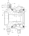
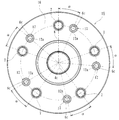
- FIG. 1 is a longitudinal sectional view showing a first embodiment of a wheel bearing device according to the present invention
- FIG. 2 is a front view showing a single hub wheel of FIG. 1
- FIG. 3 (a) is a pin of FIG.
- FIG. 4B is a longitudinal sectional view of the same
- FIG. 4 is a sectional view of an essential part showing an engaging portion of the pin of FIG.
- the side closer to the outside of the vehicle in the state assembled to the vehicle is referred to as an outer side (left side in FIG. 1), and the side closer to the center is referred to as an inner side (right side in FIG.
- This wheel bearing device has a third generation structure on the drive wheel side, and includes an inner member 1, an outer member 2, and double-row rolling elements (balls) 3, 3.
- the inner member 1 includes a hub ring 4 and a separate inner ring 5 that is press-fitted and fixed to the hub ring 4.
- the hub wheel 4 integrally has a wheel mounting flange 6 for mounting a wheel (not shown) at one end portion on the outer side, one (outer side) inner rolling surface 4a on the outer periphery, and this inner rolling.
- a small diameter step 4b extending in the axial direction from the surface 4a is formed, and a serration (or spline) 4c for torque transmission is formed on the inner periphery.
- the inner ring 5 is formed with the other (inner side) inner rolling surface 5a on the outer periphery, and is press-fitted and fixed to the small-diameter step portion 4b of the hub ring 4 via a predetermined shimoshiro.
- hub bolts 7 for fixing the wheels are implanted at equal circumferential positions of the wheel mounting flanges 6.
- a cylindrical pilot portion 8 for guiding and supporting the wheel and the brake rotor 13 in the radial direction protrudes from the outer base portion of the wheel mounting flange 6.
- the wheel mounting flange 6 of the hub wheel 4 is formed to be thin as a whole in order to reduce the weight, and on the inner side surface of the wheel mounting flange 6 to increase rigidity, a plurality of radial extending from the base portion 6a is provided.
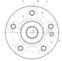
- the rib 6b is formed by forging. The rib 6b protrudes toward the inner side at the position of the hub bolt 7 to be thick, and is formed in a petal shape (see FIG. 2).
- the hub wheel 4 is made of medium and high carbon steel containing 0.40 to 0.80% by weight of carbon, such as S53C, and includes a base portion that serves as a seal land portion of the outer seal 10 described later, including the inner rolling surface 4a.
- a predetermined hardened layer having a surface hardness in the range of 58 to 64 HRC is formed by induction hardening from 6a to the small diameter step 4b. Such induction hardening improves the strength of the hub wheel 4 and suppresses fretting on the fitting surface of the inner ring 5 to improve durability.
- the inner ring 5 is made of a high carbon chrome bearing steel such as SUJ2, and is hardened in the range of 58 to 64 HRC to the core by quenching.
- the outer member 2 integrally has a vehicle body mounting flange 2b to be attached to the vehicle body (not shown) on the outer periphery, and has a double row facing the inner rolling surfaces 4a and 5a of the inner member 1 on the inner periphery.
- the outer rolling surfaces 2a and 2a are integrally formed.
- the outer member 2 is formed of medium and high carbon steel containing 0.40 to 0.80% by weight of carbon, such as S53C, like the hub wheel 4, and the double row outer rolling surfaces 2a and 2a are formed by induction hardening.
- the surface hardness is set in the range of 58 to 64 HRC.
- double-row rolling elements 3 and 3 that are circumferentially arranged by cages 9 and 9 are accommodated so as to be freely rollable. ing. Seals 10 and 11 are attached to the opening of the annular space formed between the inner member 1 and the outer member 2, and sealed inside the bearing, leakage of lubricating grease, rainwater, dust, etc. from the outside Is prevented from entering the inside of the bearing.
- the wheel bearing apparatus comprised by the double row angular contact ball bearing which used the rolling elements 3 and 3 as a ball
- the third generation structure on the drive wheel side in which the inner raceway surface 4a is formed directly on the outer periphery of the hub wheel 4 is illustrated, but the present invention is not limited to this, and a pair of inner rings are press-fitted and fixed to the small-diameter step portion of the hub wheel.
- a second generation structure or a fourth generation structure in which the hub wheel and the outer joint member are unitized and the inner rolling surface is directly formed on the outer periphery of the outer joint member may be used.
- a through hole 6c is formed in the wheel mounting flange 6 of the hub wheel 4, and a pin 12 is press-fitted and fixed to the through hole 6c.
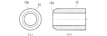
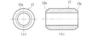
- This pin 12 is made of high carbon chrome bearing steel such as SUJ2, and is formed hollow with a pipe material as shown in FIG. 3, and a predetermined chamfered portion 12a is formed at one end.
- examples of the material of the pin 12 include carburized steel such as SCr420 and SCM415, cold rolled steel plates (JIS standard SPCC system, etc.), and carbon steel such as S50C to S55C. can do.
- This pin 12 may be left raw without being subjected to a curing process.
- the pin 12 in order to prevent wear and increase the mechanical strength, is cured in the range of 58 to 64 HRC by quenching.
- the surface hardness is set to a range of 35 to 50 HRC by a surface hardening process such as carburizing and quenching.
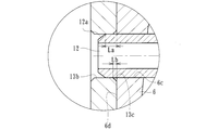
- a through hole 13 a is provided at a position corresponding to the hub bolt 7 of the brake rotor 13, and an insertion hole 13 b is provided at a position corresponding to the pin 12.
- the inner diameter of the through hole 13 a is set to be larger than the outer diameter of the hub bolt 7, and the inner diameter of the insertion hole 13 b is set to be substantially the same as the outer diameter of the pin 12.
- the brake rotor 13 is prevented from rotating with respect to the wheel mounting flange 6 by simply inserting the through hole 13a of the brake rotor 13 facing the hub bolt 7 with the chamfered portion 12a of the pin 12 as it is.
- the pin 12 can be easily inserted or press-fitted into the insertion hole 12a in a short time by the chamfered portion 12a of the pin 12, and is not detached from the wheel mounting flange 6.
- the pin 12 since the pin 12 is hardened, the pin 12 can be prevented from being damaged even if it receives a shearing force from the brake rotor 13, and durability can be improved. Moreover, since the pin 12 is formed hollow, pressure input can be suppressed, deformation of the wheel mounting flange 6 at the time of press-fitting is prevented, and the outer side of the wheel mounting flange 6 serving as a mounting surface of the brake rotor 13 The surface runout accuracy of the side surface 6d can be ensured.
- the dimension La from the outer side surface 6 d of the wheel mounting flange 6 to the chamfered portion 12 a of the pin 12 is set to be larger than the dimension Lb of the chamfered portion 13 c of the brake rotor 13. (La> Lb).
- FIG. 5 is a longitudinal sectional view showing a second embodiment of the wheel bearing device according to the present invention
- FIG. 6 is a front view of FIG. 5
- FIG. 7 (a) is a front view showing the pin of FIG.
- FIG. 8B is a cross-sectional view of the same
- FIG. 8A is a front view showing a modification of the pin of FIG. 7
- FIG. 8B is a plan view of the same.
- this embodiment basically differs from the above-described embodiment (FIG. 1) only in the pin configuration and the number of installed parts, and the same reference numerals are given to other parts, parts, and parts having the same function. Therefore, detailed description is omitted.
- This wheel bearing device has a third generation structure on the drive wheel side, and includes an inner member 14, an outer member 2, and double-row rolling elements 3, 3.
- the inner member 14 includes a hub ring 15 and a separate inner ring 5 that is press-fitted and fixed to the hub ring 15.
- the hub wheel 15 integrally has a wheel mounting flange 16 at one end portion on the outer side, and has one inner rolling surface 4a on the outer periphery and a small-diameter step portion 4b extending in the axial direction from the inner rolling surface 4a.
- a serration 4c for torque transmission is formed on the inner periphery.
- a plurality of through holes 6 c are formed in the wheel mounting flange 6 of the hub wheel 4. These through-holes 6c are respectively formed at positions of a predetermined phase angle ⁇ from the hub bolt 7, and the pins 17 are press-fitted and fixed through predetermined squeezing.
- This pin 17 is made of a high carbon chromium bearing steel such as SUJ2, and is hardened in the range of 58 to 64 HRC by quenching.
- the pin 17 is formed hollow from a pipe material, and the same chamfered portions 12 a and 12 a are formed at both ends.
- the pin 17 can be easily inserted or press-fitted into an insertion hole of a brake rotor (not shown) in a short time and the direction of the pin 17 is not determined.
- the fitting flange 16 can be press-fitted, and the press-fitting work can be simplified. Further, since the number of the pins 17 for temporary fixing is matched with the number of the hub bolts 7 and the pins 17 are press-fitted at the same phase angle ⁇ , the rotation balance of the hub wheel 15 is not lost and the rotation accuracy is improved. be able to.
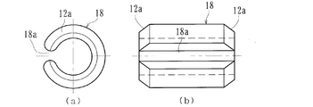
- Fig. 8 shows a modification.
- the pin 18 is a so-called spring pin formed by pressing a spring steel.
- the surface hardness is set to 45 to 50 HRC by heat treatment, and the surface is subjected to a phosphate coating treatment.
- it has the slit 18a extended in an axial direction, and the same chamfered parts 12a and 12a are formed in both ends.
- the pin 18 can be easily inserted or press-fitted into an insertion hole of a brake rotor (not shown) in a short time and the direction of the pin 18 can be determined without determining the directionality.
- the fitting flange 16 can be press-fitted, and the press-fitting work can be further simplified.
- an outer ring rotation having a wheel mounting flange on an outer member.
- it may be of a type and can be implemented in various forms without departing from the gist of the present invention.
- the scope of the present invention is defined by the terms of the claims, and includes the equivalent meanings of the claims and all modifications within the scope.
- a wheel bearing device has a wheel mounting flange for mounting a wheel at one end via a brake rotor, and has a second to fourth generation structure with a brake rotor temporarily fixed. It can be applied to a bearing device.
- Retainer 10 ... Seal on the outer side 11 ... Seals 12, 17, 18 on the inner side ... Pins 12a, 13c ... ... Chamfer 13 ... ⁇ Brake rotor 13b ⁇ Insertion hole 50 ⁇ Wheel bearing device 51 ⁇ ⁇ ⁇ ⁇ Wheel mounting flange 51a ?? Through hole 51b ; Side surface 52 of the wheel mounting flange ........... Hub wheel 52a, 53a ... .... Inner rolling surface 52b ... Small diameter step 52c ... Serration 52d ... Caulking part 53 ... ... Inner ring 54 ... Inner member 55 ... Outer member 55a ... Outer rolling surface 5b ... Body mounting flange 56 ... Cage 57 ... Ball 58 ... ... Hub bolts 59, 60 ... Seal 61 ... Pin 61a ... Chamfer 62 ... ... Brake rotor 62a ... Insertion hole ⁇ ... Phase angle
Landscapes
- Engineering & Computer Science (AREA)
- General Engineering & Computer Science (AREA)
- Mechanical Engineering (AREA)
- Rolling Contact Bearings (AREA)
- Braking Arrangements (AREA)
Priority Applications (2)
| Application Number | Priority Date | Filing Date | Title |
|---|---|---|---|
| DE112009002483.1T DE112009002483B4 (de) | 2008-10-23 | 2009-10-21 | Radlagervorrichtung für ein Fahrzeug |
| US13/091,230 US8783963B2 (en) | 2008-10-23 | 2011-04-21 | Wheel bearing apparatus for a vehicle |
Applications Claiming Priority (2)
| Application Number | Priority Date | Filing Date | Title |
|---|---|---|---|
| JP2008-272941 | 2008-10-23 | ||
| JP2008272941A JP5752873B2 (ja) | 2008-10-23 | 2008-10-23 | 車輪用軸受装置 |
Related Child Applications (1)
| Application Number | Title | Priority Date | Filing Date |
|---|---|---|---|
| US13/091,230 Continuation US8783963B2 (en) | 2008-10-23 | 2011-04-21 | Wheel bearing apparatus for a vehicle |
Publications (1)
| Publication Number | Publication Date |
|---|---|
| WO2010047097A1 true WO2010047097A1 (ja) | 2010-04-29 |
Family
ID=42119150
Family Applications (1)
| Application Number | Title | Priority Date | Filing Date |
|---|---|---|---|
| PCT/JP2009/005506 Ceased WO2010047097A1 (ja) | 2008-10-23 | 2009-10-21 | 車輪用軸受装置 |
Country Status (4)
| Country | Link |
|---|---|
| US (1) | US8783963B2 (enExample) |
| JP (1) | JP5752873B2 (enExample) |
| DE (1) | DE112009002483B4 (enExample) |
| WO (1) | WO2010047097A1 (enExample) |
Cited By (1)
| Publication number | Priority date | Publication date | Assignee | Title |
|---|---|---|---|---|
| US20140161382A1 (en) * | 2012-12-07 | 2014-06-12 | Aktiebolaget Skf | Flanged bearing ring for the hub of a motor vehicle wheel |
Families Citing this family (10)
| Publication number | Priority date | Publication date | Assignee | Title |
|---|---|---|---|---|
| WO2013151195A1 (ko) * | 2012-04-06 | 2013-10-10 | 주식회사 일진글로벌 | 휠 베어링 체결 구조 및 체결 방법 |
| DE102013103619A1 (de) * | 2012-12-12 | 2014-06-26 | Dr. Ing. H.C. F. Porsche Aktiengesellschaft | Radnaben-Bremsscheiben-Verbund |
| JP6082588B2 (ja) * | 2012-12-20 | 2017-02-15 | 株式会社ジェイテクト | 車両用軸受装置 |
| JP6760149B2 (ja) * | 2016-08-30 | 2020-09-23 | 日本精工株式会社 | 車輪支持用転がり軸受ユニット |
| JP6575542B2 (ja) * | 2017-02-07 | 2019-09-18 | トヨタ自動車株式会社 | タイヤホイール、ブレーキロータ及びハブの組付構造 |
| KR101928912B1 (ko) * | 2017-04-13 | 2019-03-14 | 주식회사 한양정밀 | 브레이크 디스크 및 브레이크 디스크의 제조 방법 |
| JP2019073145A (ja) * | 2017-10-16 | 2019-05-16 | 日本精工株式会社 | ハブユニット軸受 |
| JP7787661B2 (ja) * | 2021-07-12 | 2025-12-17 | Ntn株式会社 | 車輪用軸受装置 |
| CN114517804B (zh) * | 2022-02-14 | 2024-01-26 | 陈国强 | 一种能有效防止螺栓因疲劳破坏折断的装置 |
| JP2024108970A (ja) * | 2023-01-31 | 2024-08-13 | ダイハツ工業株式会社 | 分解構造 |
Citations (8)
| Publication number | Priority date | Publication date | Assignee | Title |
|---|---|---|---|---|
| JPS6031513U (ja) * | 1983-02-14 | 1985-03-04 | 日発精密工業株式会社 | スプリングピン |
| JPH0538409U (ja) * | 1991-10-25 | 1993-05-25 | 積水化学工業株式会社 | 機械部品の位置決め構造 |
| JP2002275651A (ja) * | 2001-03-16 | 2002-09-25 | Honda Motor Co Ltd | ステンレス鋼の潤滑皮膜処理方法 |
| JP2003214441A (ja) * | 2002-01-21 | 2003-07-30 | Nsk Ltd | 制動用回転部材付転がり軸受ユニット |
| JP2005195061A (ja) * | 2004-01-05 | 2005-07-21 | Nsk Ltd | ディスク付車輪用軸受ユニットの製造方法とその製造装置 |
| JP2007307933A (ja) * | 2006-05-16 | 2007-11-29 | Ntn Corp | 車輪用軸受装置 |
| JP2007314138A (ja) * | 2006-05-29 | 2007-12-06 | Jtekt Corp | ハブユニット |
| JP2008013072A (ja) * | 2006-07-06 | 2008-01-24 | Nsk Ltd | アクスル構造 |
Family Cites Families (11)
| Publication number | Priority date | Publication date | Assignee | Title |
|---|---|---|---|---|
| DE1806566C3 (de) | 1968-11-02 | 1978-07-13 | Dr.Ing.H.C. F. Porsche Ag, 7000 Stuttgart | Befestigungsvorrichtung für ein Rad an einer Nabe bei Kraftfahrzeugen |
| JPS52110291U (enExample) * | 1976-02-19 | 1977-08-22 | ||
| JPS6031513A (ja) | 1983-07-30 | 1985-02-18 | Mitsui Toatsu Chem Inc | 塩化ビニルグラフト共重合樹脂の製造方法 |
| JPH0538409A (ja) | 1991-08-05 | 1993-02-19 | Matsushita Electric Ind Co Ltd | 車載用空気清浄器 |
| US5443316A (en) * | 1993-06-24 | 1995-08-22 | The Budd Company | Live spindle hub with inboard bearing retention |
| DE19700313C2 (de) * | 1996-01-24 | 2003-02-20 | Gkn Automotive Gmbh | Radnaben-Gelenk-Einheit mit Zwischenring |
| IT1291044B1 (it) * | 1997-02-21 | 1998-12-14 | Skf Ind Spa | Configurazione per l'accoppiamento del freno al gruppo cuscinetto/ mozzo di una ruota di veicolo. |
| US6575637B1 (en) * | 1999-09-10 | 2003-06-10 | Ntn Corporation | Brake rotor and wheel bearing assembly |
| JP2003254363A (ja) * | 2002-03-06 | 2003-09-10 | Nsk Ltd | 制動用回転部材付転がり軸受ユニット |
| JP2007069746A (ja) | 2005-09-07 | 2007-03-22 | Nsk Ltd | 軸受ユニット |
| JP2007309513A (ja) * | 2006-04-20 | 2007-11-29 | Isel Co Ltd | 固定構造および固定方法 |
-
2008
- 2008-10-23 JP JP2008272941A patent/JP5752873B2/ja active Active
-
2009
- 2009-10-21 DE DE112009002483.1T patent/DE112009002483B4/de active Active
- 2009-10-21 WO PCT/JP2009/005506 patent/WO2010047097A1/ja not_active Ceased
-
2011
- 2011-04-21 US US13/091,230 patent/US8783963B2/en active Active
Patent Citations (8)
| Publication number | Priority date | Publication date | Assignee | Title |
|---|---|---|---|---|
| JPS6031513U (ja) * | 1983-02-14 | 1985-03-04 | 日発精密工業株式会社 | スプリングピン |
| JPH0538409U (ja) * | 1991-10-25 | 1993-05-25 | 積水化学工業株式会社 | 機械部品の位置決め構造 |
| JP2002275651A (ja) * | 2001-03-16 | 2002-09-25 | Honda Motor Co Ltd | ステンレス鋼の潤滑皮膜処理方法 |
| JP2003214441A (ja) * | 2002-01-21 | 2003-07-30 | Nsk Ltd | 制動用回転部材付転がり軸受ユニット |
| JP2005195061A (ja) * | 2004-01-05 | 2005-07-21 | Nsk Ltd | ディスク付車輪用軸受ユニットの製造方法とその製造装置 |
| JP2007307933A (ja) * | 2006-05-16 | 2007-11-29 | Ntn Corp | 車輪用軸受装置 |
| JP2007314138A (ja) * | 2006-05-29 | 2007-12-06 | Jtekt Corp | ハブユニット |
| JP2008013072A (ja) * | 2006-07-06 | 2008-01-24 | Nsk Ltd | アクスル構造 |
Cited By (2)
| Publication number | Priority date | Publication date | Assignee | Title |
|---|---|---|---|---|
| US20140161382A1 (en) * | 2012-12-07 | 2014-06-12 | Aktiebolaget Skf | Flanged bearing ring for the hub of a motor vehicle wheel |
| US8992092B2 (en) * | 2012-12-07 | 2015-03-31 | Aktiebolaget Skf | Flanged bearing ring for the hub of a motor vehicle wheel |
Also Published As
| Publication number | Publication date |
|---|---|
| DE112009002483T5 (de) | 2012-08-02 |
| US8783963B2 (en) | 2014-07-22 |
| DE112009002483B4 (de) | 2022-09-15 |
| US20110194797A1 (en) | 2011-08-11 |
| JP5752873B2 (ja) | 2015-07-22 |
| JP2010100156A (ja) | 2010-05-06 |
Similar Documents
| Publication | Publication Date | Title |
|---|---|---|
| JP5752873B2 (ja) | 車輪用軸受装置 | |
| JP2010100156A5 (enExample) | ||
| JP5134356B2 (ja) | 車輪用軸受装置 | |
| JP5641705B2 (ja) | 車輪用軸受装置 | |
| JP4526998B2 (ja) | 駆動車輪用軸受装置 | |
| JP2006275174A (ja) | 駆動車輪用軸受装置 | |
| JP4489672B2 (ja) | 車輪用軸受装置 | |
| JP2007126087A (ja) | 車輪用軸受装置 | |
| JP5417239B2 (ja) | 車輪用軸受装置およびその製造方法 | |
| JP2010089664A (ja) | 車輪用軸受装置 | |
| JP4998983B2 (ja) | 車輪用軸受装置 | |
| JP2006329320A (ja) | 車輪用軸受装置 | |
| JP2007196936A (ja) | 車輪用軸受装置 | |
| JP5147100B2 (ja) | 車輪用軸受装置 | |
| JP4994717B2 (ja) | 車輪用軸受装置 | |
| JP4420341B2 (ja) | 背面組合わせタイプの複列アンギュラ玉軸受 | |
| JP5024850B2 (ja) | 車輪用軸受装置 | |
| JP2005297878A (ja) | ブレーキロータ付き車輪用軸受装置 | |
| JP2007218292A (ja) | 車輪用軸受装置 | |
| JP2008018767A (ja) | ドライブシャフトアセンブリ | |
| JP2010047092A (ja) | 車輪用軸受装置 | |
| JP2007153051A (ja) | 車輪用軸受装置 | |
| JP4986115B2 (ja) | 車輪用軸受装置 | |
| JP2008045674A (ja) | 車輪用軸受装置 | |
| JP2005306290A (ja) | ブレーキロータ付き車輪用軸受装置 |
Legal Events
| Date | Code | Title | Description |
|---|---|---|---|
| 121 | Ep: the epo has been informed by wipo that ep was designated in this application |
Ref document number: 09821797 Country of ref document: EP Kind code of ref document: A1 |
|
| WWE | Wipo information: entry into national phase |
Ref document number: 1120090024831 Country of ref document: DE |
|
| 122 | Ep: pct application non-entry in european phase |
Ref document number: 09821797 Country of ref document: EP Kind code of ref document: A1 |