WO2010044320A1 - マグネシウム合金及びその製造方法 - Google Patents
マグネシウム合金及びその製造方法 Download PDFInfo
- Publication number
- WO2010044320A1 WO2010044320A1 PCT/JP2009/065701 JP2009065701W WO2010044320A1 WO 2010044320 A1 WO2010044320 A1 WO 2010044320A1 JP 2009065701 W JP2009065701 W JP 2009065701W WO 2010044320 A1 WO2010044320 A1 WO 2010044320A1
- Authority
- WO
- WIPO (PCT)
- Prior art keywords
- phase
- alloy
- magnesium alloy
- αmg
- long
- Prior art date
- Legal status (The legal status is an assumption and is not a legal conclusion. Google has not performed a legal analysis and makes no representation as to the accuracy of the status listed.)
- Ceased
Links
Images




Classifications
-
- C—CHEMISTRY; METALLURGY
- C22—METALLURGY; FERROUS OR NON-FERROUS ALLOYS; TREATMENT OF ALLOYS OR NON-FERROUS METALS
- C22F—CHANGING THE PHYSICAL STRUCTURE OF NON-FERROUS METALS AND NON-FERROUS ALLOYS
- C22F1/00—Changing the physical structure of non-ferrous metals or alloys by heat treatment or by hot or cold working
- C22F1/06—Changing the physical structure of non-ferrous metals or alloys by heat treatment or by hot or cold working of magnesium or alloys based thereon
-
- C—CHEMISTRY; METALLURGY
- C22—METALLURGY; FERROUS OR NON-FERROUS ALLOYS; TREATMENT OF ALLOYS OR NON-FERROUS METALS
- C22C—ALLOYS
- C22C23/00—Alloys based on magnesium
- C22C23/04—Alloys based on magnesium with zinc or cadmium as the next major constituent
-
- C—CHEMISTRY; METALLURGY
- C22—METALLURGY; FERROUS OR NON-FERROUS ALLOYS; TREATMENT OF ALLOYS OR NON-FERROUS METALS
- C22C—ALLOYS
- C22C23/00—Alloys based on magnesium
- C22C23/06—Alloys based on magnesium with a rare earth metal as the next major constituent
Definitions
- the present invention relates to a magnesium alloy and a method for producing the same. Specifically, the present invention relates to a magnesium alloy having high strength and high ductility, and a method for producing the same.
- magnesium alloys have the lowest density, light weight, and high strength among the alloys in practical use, so they are being applied to electrical housings, automobile wheels, suspension parts, engine parts, etc. It has been.
- high mechanical properties are required for parts related to automobiles, and as a magnesium alloy to which elements such as Gd and Zn are added, materials of specific forms are manufactured by the single roll method and rapid solidification method. (For example, refer to Patent Document 1 and Patent Document 2).
- a conventional magnesium alloy having a long-period laminated structure phase has a tensile strength of about 300 MPa but has an elongation of less than 10%.
- a commercially available AZ-based magnesium alloy can achieve an elongation of about 15% by annealing at 300 ° C. for about 1 hour, the tensile strength was about 150 MPa.
- the present invention was devised in view of the above points, and provides a magnesium alloy having excellent tensile strength and good ductility, and can obtain such a magnesium alloy, sufficiently corresponding to actual production.
- An object of the present invention is to provide a method for producing a magnesium alloy that can be used.
- the magnesium alloy of the present invention is a magnesium alloy composed of an Mg—Zn—Y-based alloy containing Zn and Y as essential components and the balance being Mg and inevitable impurities.
- the alloy structure of the Mg—Zn—Y alloy has an ⁇ Mg phase and a long-period laminate structure phase, and at least a part of the long-period laminate structure phase exists in a lamellar form with the ⁇ Mg phase.
- At least a part of the lamellar tissue is curved or bent, and further, a discontinuous interface between the ⁇ Mg phase and the long-period laminate structure phase is formed in the curved or bent portion, or the curved or bent Grain boundaries between the ⁇ Mg phase and the long-period stacked structure phase are formed in the bent portion.
- the alloy structure of the Mg—Zn—Y alloy has an ⁇ Mg phase and a long-period stacked structure phase (hereinafter referred to as “LPSO: Long Period Stacking Order”), and at least a part of the LPSO. It exists in a lamellar form with the ⁇ Mg phase, and at least a part of the lamellar structure is curved or bent, and further, the discontinuous interface (grain boundary) between the ⁇ Mg phase and LPSO in the curved or bent part. Is formed, or a grain boundary of ⁇ Mg phase and LPSO is formed in a curved or bent portion, whereby excellent tensile strength and good ductility can be realized.
- LPSO Long Period Stacking Order
- a discontinuous interface (grain boundary) between the ⁇ Mg phase and LPSO is formed in the curved or bent portion.
- the curved or bent structure of LPSO forms a linear LPSO structure
- the grain boundary between the ⁇ Mg phase and the LPSO at the curved or bent portion is a stable structure, excellent tensile strength and good ductility can be realized.
- the magnesium alloy of the present invention is a magnesium alloy composed of an Mg—Zn—Y based alloy containing Zn and Y as essential components and the balance being Mg and inevitable impurities.
- the alloy structure of the Y-based alloy has a needle-like or plate-like long-period laminated structure phase.
- an Mg—Zn—Y alloy containing Zn and Y as essential components and the balance consisting of Mg and inevitable impurities is cast.
- a heat treatment step for performing a heat treatment wherein the heat treatment step is performed in a temperature range of 350 ° C. to 500 ° C. and in a time range of 0.5 hours to 10 hours. .
- FIG. 5 (a) shows the relationship between heat treatment temperature and mechanical properties (tensile strength, 0.2% proof stress and elongation) when Mg 97 Zn 1 Y 2 alloy is annealed for 1 hour
- FIG. 5 (b) shows the relationship between the heat treatment temperature and mechanical properties (tensile strength, 0.2% proof stress and elongation) in the case where the Mg 96 Zn 2 Y 2 alloy is annealed for 1 hour.
- an elongation of approximately 10% or more can be obtained while achieving a tensile strength of approximately 300 MPa or higher at a heat treatment temperature of 350 ° C. or higher. Is performed at a temperature of 350 ° C. or higher.
- symbol a indicates tensile strength
- symbol b indicates 0.2% proof stress
- symbol c indicates elongation.
- the reason why the heat treatment step is performed at a temperature of 500 ° C. or less is that if it exceeds 500 ° C., the melting point of the magnesium alloy is approached, and the heat treatment temperature is limited to 500 ° C. or less in consideration of actual production.
- the magnesium phase having a 2H structure contained in the long-period laminated structure phase disappears and a long-period laminated structure phase that is a stable structure appears.
- a tensile strength of 300 MPa or more can be realized, and an elongation of about 12% or more can be realized.
- the alloy structure has an ⁇ Mg phase and LPSO.
- the LPSO is present in a lamellar form with the ⁇ Mg phase, and at least a part of the tissue present in the lamellar form is curved or bent, and the ⁇ Mg phase and the LPSO are further bent or bent.
- Mg—Zn—Y having a discontinuous interface (grain boundary), ⁇ Mg phase and LPSO grain boundary formed in a curved or bent portion, or needle-like or plate-like LPSO phase
- a magnesium alloy composed of a base alloy can be obtained.
- the Mg—Zn—Y alloy having such a structure can achieve excellent tensile strength and good ductility.
- the heat treatment step is preferably performed at a temperature of 400 ° C. or higher, specifically, within a temperature range of 400 ° C. or higher and 500 ° C. or lower.
- the heat treatment temperature is 450 ° C. or higher, a needle-like or plate-like long-period laminated structure phase appears, realizing a tensile strength of 300 MPa or more and an elongation of approximately 18% or more. can do. Accordingly, it is more preferable that the heat treatment step is performed at a temperature of 450 ° C. or higher, specifically, a temperature range of 450 ° C. or higher and 500 ° C. or lower.
- the reason for setting the heat treatment time to 0.5 hours or more is to obtain desired mechanical properties, specifically, to realize a tensile strength of 300 MPa or more and an elongation of 10% or more.
- the reason for setting the heat treatment time to 10 hours or less is that even if the heat treatment is performed for more than 10 hours, the mechanical properties and the structure do not vary so much.
- the magnesium alloy of the present invention excellent tensile strength and good ductility can be realized. Moreover, in the manufacturing method of the magnesium alloy of this invention, the magnesium alloy which has the outstanding tensile strength and favorable ductility can be obtained. In particular, in the method for producing a magnesium alloy of the present invention, by combining plastic processing and structure control by heat treatment, restrictions on processing conditions and processing methods are relaxed compared to structure control by plastic processing alone, and it fully supports actual production. can do.
- FIG. 1 (a) is a micrograph showing the crystal structure of an annealed material of Mg 96 Zn 2 Y 2 at 400 ° C. for 1 hour
- FIG. 1 (b) is 450 ° C. of Mg 96 Zn 2 Y 2 alloy at 1 ° C
- FIG. 1 (c) is a photomicrograph showing the crystal structure of the annealed material at 475 ° C. for 1 hour of the Mg 96 Zn 2 Y 2 alloy
- FIG. ) Is a photomicrograph showing the crystal structure of the annealed material of Mg 96 Zn 2 Y 2 alloy at 500 ° C. for 1 hour.
- the magnesium alloy of the present invention is an Mg—Zn—Y based alloy containing Zn and Y as essential components and the balance being composed of Mg and inevitable impurities.
- Mg 97 Zn 1 Y 2 An explanation will be given by taking an alloy or an Mg 96 Zn 2 Y 2 alloy as an example.
- the magnesium alloy 1 has LPSO 2 and ⁇ Mg phase 3 in its alloy structure.
- LPSO and ⁇ Mg phase are present in a lamellar shape, and there is no continuity between LPSO and ⁇ Mg phase at the bending portion of the tissue present in the lamellar shape (region indicated by symbol d in the figure) Discontinuous interfaces (grain boundaries) are formed.
- 1B to 1D have a needle-like or plate-like LPSO.
- the magnesium alloy of the present invention has LPSO.
- LPSO is a precipitate that precipitates in the grain and boundary of the magnesium alloy, and has a structure in which the arrangement of bottom atomic layers in the HCP structure is repeated with a long periodic rule in the bottom normal direction, that is, a long period. A laminated structure. This precipitation of LPSO improves the mechanical properties (tensile strength, 0.2% proof stress and elongation) of the magnesium alloy.
- the magnesium alloy of the present invention has a discontinuous interface (grain boundary) between LPSO and ⁇ Mg phase at the bent portion of the structure existing in a lamellar shape.
- the magnesium phase having a 2H structure contained in LPSO disappears, and a new LPSO appears.
- a kink appears as a clear interface by recovery, thereby discontinuous interface. It is considered that (grain boundaries) are visually recognized.
- the new LPSO which appears by recovery is a stable structure, the mechanical properties (tensile strength, 0.2% yield strength and elongation) are improved.
- the magnesium alloy of the present invention has a needle-like or plate-like LPSO.
- the LPSO has a needle shape or a plate shape
- the kink band of the LPSO is sharpened and the LPSO is finely dispersed.
- the mechanical properties of the magnesium alloy tensile strength, 0.2%) Yield strength and elongation
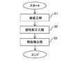
- FIG. 2 is a flowchart for explaining a method for producing a magnesium alloy to which the present invention is applied.
- a casting step S1 in the manufacturing method of the magnesium alloy to which the present invention is applied, first, casting is performed by a casting step S1.
- a casting material containing LPSO and ⁇ -Mg phase is formed by casting a Mg—Zn—Y alloy containing Zn and Y as essential components and the balance being Mg and inevitable impurities.
- the cast material formed by the casting process is an Mg 97 Zn 1 Y 2 alloy and the case of an Mg 96 Zn 2 Y 2 alloy will be described as examples.
- a plastic working step S2 is performed on the cast material.
- the plastic processing in this plastic processing step is, for example, extrusion processing, forging processing, rolling processing or drawing processing, and the plastic processed product obtained by plastic processing of the cast material has tensile strength, elongation, 0.2%. The yield strength will be significantly improved.
- the plastic processed product is subjected to heat treatment (specifically, annealing treatment) within a temperature range of 350 ° C. to 500 ° C. and within a time range of 0.5 hours to 10 hours.
- heat treatment specifically, annealing treatment
- the structure is controlled by the heat treatment process so that the crystal grain size of the ⁇ Mg phase becomes 7 ⁇ m to 15 ⁇ m.
- the crystal grain size of the ⁇ Mg phase becomes 7 ⁇ m to 15 ⁇ m.
- a crystal grain size of 7 ⁇ m can be obtained by performing heat treatment at 400 ° C. for 1 hour
- a crystal grain size of 10 ⁇ m can be obtained by performing heat treatment at 500 ° C. for 1 hour.
- a crystal grain size of 15 ⁇ m can be obtained by performing a heat treatment for 10 hours.
- the structure of the ⁇ Mg phase crystal grain size is controlled to 7 ⁇ m to 15 ⁇ m in the case of Mg 97 Zn 1 Y 2 alloy by controlling the structure within such a range to obtain a tensile strength of approximately 300 MPa or more. This is because both elongations of approximately 10% or more can be realized (see FIG. 5A).
- FIG. 3 (a) is a micrograph showing the crystal structure of the extruded material of Mg 97 Zn 1 Y 2 alloy
- Fig. 3 (b) is an annealing of Mg 97 Zn 1 Y 2 alloy at 300 ° C for 1 hour
- FIG. 3 (c) is a micrograph showing the crystal structure of the annealed material at 400 ° C. for 1 hour in the Mg 97 Zn 1 Y 2 alloy
- FIG. 97 Zn 1 Y 2 500 °C alloy is a photomicrograph showing the crystal structure of the annealed material an hour.
- 3 (a) to 3 (d) the magnesium alloys obtained by the magnesium alloy manufacturing method to which the present invention is applied are shown in FIGS.
- Alloy 1 has LPSO 2 and ⁇ Mg phase 3 in its alloy structure.
- the black portions are LPSO, and the granular portions are ⁇ Mg phases.
- the structure is controlled by the heat treatment process so that the crystal grain size of the ⁇ Mg phase becomes 3 ⁇ m to 10 ⁇ m. Specifically, by performing heat treatment within a temperature range of 350 ° C. or more and 500 ° C. or less and within a time range of 0.5 hours or more and 10 hours or less, the crystal grain size of the ⁇ Mg phase becomes 3 ⁇ m to 10 ⁇ m. To control the organization. As an example, a crystal grain size of 3 ⁇ m can be obtained by performing heat treatment at 400 ° C. for 1 hour, and a crystal grain size of 10 ⁇ m can be obtained by performing heat treatment at 500 ° C. for 1 hour.
- the structure of the ⁇ Mg phase crystal grain size is controlled to 3 ⁇ m to 10 ⁇ m in the case of the Mg 96 Zn 2 Y 2 alloy, by controlling the structure within such a range, This is because both elongations of approximately 10% or more can be realized (see FIG. 5B).
- FIG. 3 (e) is a photomicrograph showing the crystal structure of the extruded material of Mg 96 Zn 2 Y 2 alloy
- FIG. 3 (f) is an annealing of Mg 96 Zn 2 Y 2 alloy at 300 ° C. for 1 hour
- FIG. 3 (g) is a micrograph showing the crystal structure of the annealed material at 400 ° C. for 1 hour of the Mg 96 Zn 2 Y 2 alloy
- FIG. 96 Zn 2 Y 2 500 °C alloy is a photomicrograph showing the crystal structure of the annealed material an hour.
- 3 (e) to 3 (h) the magnesium alloys obtained by the magnesium alloy manufacturing method to which the present invention is applied are shown in FIGS.
- Alloy 1 has LPSO 2 and ⁇ Mg phase 3 in its alloy structure.
- the black portions are LPSO, and the granular portions are ⁇ Mg phases.
- FIG. 4A is a photomicrograph showing the crystal structure of the annealed material of Mg 96 Zn 2 Y 2 alloy at 400 ° C. for 1 hour
- FIG. 4B is 450 of the Mg 96 Zn 2 Y 2 alloy
- FIG. 4 (c) is a photomicrograph showing the crystal structure of the annealed material at 500 ° C. for 1 hour in the Mg 96 Zn 2 Y 2 alloy.
- intermetallic compound Mg 3 Zn 3 Y 2 is formed.
- the part indicated by symbol e is the intermetallic compound Mg 3 Zn 3 Y 2 .
- an Mg 96 Zn 2 Y 2 alloy is used.
- heat treatment specifically, annealing treatment
- a temperature of 400 ° C. or higher an elongation of approximately 12% or more can be achieved while achieving a tensile strength of approximately 300 MPa or more.
- a magnesium alloy can be obtained.
- heat treatment specifically, annealing treatment
- a magnesium alloy that can achieve an elongation of approximately 18% or more while achieving a tensile strength of approximately 300 MPa or more. Can be obtained.
- FIG. 6A is a photomicrograph showing the crystal structure of the annealed material of Mg 96 Zn 2 Y 2 alloy at 400 ° C. for 1 hour. From the micrograph shown in FIG. It turns out that it has precipitated in the grain.
- FIG. 6B is a photomicrograph showing the crystal structure of the annealed material of Mg 96 Zn 2 Y 2 alloy at 425 ° C. for 1 hour. From the micrograph shown in FIG. It can be clearly seen from FIG.
- FIG. 6C is a photomicrograph showing the crystal structure of the annealed material at 450 ° C. for 1 hour of the Mg 96 Zn 2 Y 2 alloy. From the micrograph shown in FIG.
- FIG. 6 (d) is a micrograph showing the crystal structure of the annealed material at 475 ° C. for 1 hour of the Mg 96 Zn 2 Y 2 alloy. From the micrograph shown in FIG. 6 (d), grains of ⁇ Mg phase It can be seen that needle-like or plate-like LPSO grows in the boundary and / or within the grains, and the needle-like or plate-like LPSOs are united with each other. Further, FIG. 6 (e) is a micrograph showing the crystal structure of the annealed material of Mg 96 Zn 2 Y 2 alloy at 500 ° C. for 1 hour.
- the appearing LPSO exhibits a needle-like structure or a plate-like structure, so that the kink band is sharper than the extruded material.
- LPSO is finely dispersed. Therefore, as described above, it is possible to obtain a magnesium alloy that can achieve an elongation of approximately 18% or more while achieving a tensile strength of approximately 300 MPa or more.
- FIG. 7A is a photomicrograph showing the crystal structure of the annealed material at 500 ° C. for 1 hour in the Mg 97 Zn 1 Y 2 alloy
- FIG. 7B is 500 ° C. in the Mg 97 Zn 1 Y 2 alloy
- FIG. 7C is a photomicrograph showing the crystal structure of the annealed material for 5 hours
- FIG. 7C is a photomicrograph showing the crystal structure of the annealed material at 500 ° C. for 10 hours for the Mg 97 Zn 1 Y 2 alloy.
- the Mg 97 Zn 1 Y 2 alloy which is a magnesium alloy to which the present invention is applied, has improved thermal stability. It turns out that it is excellent.
- the recrystallization temperature of the magnesium alloy is about 300 ° C.
- the crystal grain size grows to increase the elongation. Is improved, but the tensile strength is extremely reduced.
- the black portions are LPSO and the granular portions are ⁇ Mg phases.
- FIG. 7 (d) is a photomicrograph showing the crystal structure of the annealed material of Mg 96 Zn 2 Y 2 alloy at 500 ° C. for 1 hour
- FIG. 7 (e) is a 500 photo of Mg 96 Zn 2 Y 2 alloy
- FIG. 7 (f) is a photomicrograph showing the crystal structure of the annealed material at 500 ° C. for 10 hours of the Mg 96 Zn 2 Y 2 alloy.
- the crystal structure shown in FIG. 7 (d) and the crystal structure shown in FIG. 7 (f) are not greatly different in crystal grain size, and the Mg 96 Zn 2 Y 2 alloy, which is a magnesium alloy to which the present invention is applied, is thermally stable. It turns out that it is excellent in.
- the black portions are LPSO and the granular portions are ⁇ Mg phases.
- FIG. 8A is a micrograph showing the crystal structure of the annealed material of Mg 96 Zn 2 Y 2 alloy at 400 ° C. for 1 hour.
- the crystal orientation of LPSO It can be seen that there is no regularity in the orientation of the crystal orientation of the ⁇ Mg phase and the orientation of the crystal orientation is disordered.
- FIG. 8 (b) is a micrograph showing the crystal structure of the annealed material of Mg 96 Zn 2 Y 2 at 500 ° C. for 1 hour. In the micrograph shown in FIG.
- the same LPSO the same LPSO
- the orientations of the crystal orientations are the same, and the orientation of the crystal orientation in any LPSO is the same as the crystal orientation of any of the adjacent ⁇ Mg phases.
- the orientation of crystal orientation in any LPSO may be the same as both of the adjacent ⁇ Mg phases.
- the LPSO appears in the ⁇ Mg phase grain boundaries or in the crystal grains, and may appear in the crystal grain boundaries and crystal grains.
- Example shown here is an example and does not limit this invention.
- Example (1) First, as a method for producing a magnesium alloy according to Example (1) of the present invention, Zn is 1 atomic%, Y is 2 atomic%, and the balance is Mg and an inevitable impurity Mg—Zn—Y alloy in an argon gas atmosphere. The melting was performed in the high frequency melting furnace. Next, the heat-dissolved material was cast with a mold to produce an ingot (cast material) of ⁇ 29 mm ⁇ L60 mm.
- plastic processing is performed under the conditions of an extrusion temperature of 350 ° C., an extrusion ratio of 10 and an extrusion speed of 2.5 mm / s, and then heat treatment (annealing) for 1 hour at a heat treatment temperature of 100 ° C. to 500 ° C. What was done was made.
- the Mg 97 Zn 1 Y 2 alloy obtained by the magnesium alloy production method of Example (1) of the present invention is approximately 300 MPa when annealed at a temperature of 350 ° C. or higher. While achieving the above tensile strength, it is possible to achieve an elongation of approximately 10% or more. Further, as is apparent from FIG. 5 (a), when the Mg 97 Zn 1 Y 2 alloy obtained by the magnesium alloy production method of Example (1) of the present invention is annealed at a temperature of 400 ° C. or higher, Achieving a tensile strength of approximately 300 MPa or more and an elongation of approximately 12% or more. When annealed at a temperature of 450 ° C. or more, a tensile strength of approximately 300 MPa or more is achieved and an elongation of approximately 18% or more is achieved. be able to.
- Example (2) In addition, as a manufacturing method of the magnesium alloy of Example (2) of the present invention, Zn is 2 atomic%, Y is 2 atomic%, and the balance is Mg and an inevitable impurity Mg—Zn—Y alloy in an argon gas atmosphere. The melting was performed in the high frequency melting furnace. Next, the heat-dissolved material was cast with a mold to produce an ingot (cast material) of ⁇ 29 mm ⁇ L60 mm.
- plastic processing is performed under the conditions of an extrusion temperature of 350 ° C., an extrusion ratio of 10 and an extrusion speed of 2.5 mm / s, and then heat treatment (annealing) for 1 hour at a heat treatment temperature of 100 ° C. to 500 ° C. What was done was made.
- the Mg 96 Zn 2 Y 2 alloy obtained by the magnesium alloy production method of Example (2) of the present invention is approximately 300 MPa when annealed at a temperature of 350 ° C. or higher. While achieving the above tensile strength, it is possible to achieve an elongation of approximately 10% or more. Further, as apparent from FIG. 5 (b), when the Mg 96 Zn 2 Y 2 alloy obtained by the magnesium alloy manufacturing method of Example (2) of the present invention was annealed at a temperature of 400 ° C. or higher, Achieving a tensile strength of approximately 300 MPa or more and an elongation of approximately 12% or more. When annealed at a temperature of 450 ° C. or more, a tensile strength of approximately 300 MPa or more is achieved and an elongation of approximately 18% or more is achieved. be able to.
Landscapes
- Chemical & Material Sciences (AREA)
- Engineering & Computer Science (AREA)
- Materials Engineering (AREA)
- Mechanical Engineering (AREA)
- Metallurgy (AREA)
- Organic Chemistry (AREA)
- Physics & Mathematics (AREA)
- Thermal Sciences (AREA)
- Crystallography & Structural Chemistry (AREA)
- Forging (AREA)
Abstract
優れた引張強度と良好な延性を有するマグネシウム合金を提供することを目的とする。そのために、必須成分としてZnとYとを含有し、残部がMgと不可避的不純物とからなるMg-Zn-Y系合金であって、Mg-Zn-Y系合金の合金組織中に、αMg相とLPSOを有し、LPSOとαMg相とがラメラ状に存在すると共に、ラメラ状に存在する組織の一部が湾曲または屈曲している。更に、湾曲または屈曲している部分でαMg相とLPSOの不連続界面若しくは粒界が形成されている。
Description
本発明はマグネシウム合金及びその製造方法に関する。詳しくは、高強度であると共に高延性であるマグネシウム合金及びその製造方法に係るものである。
一般に、マグネシウム合金は、実用化されている合金の中で最も密度が低く軽量で強度も高いため、電気製品の筐体や、自動車のホイール、足回り部品、エンジン回り部品等への適用が進められている。
特に、自動車に関連する用途の部品においては、高い機械的特性が要求されるため、GdやZn等の元素を添加したマグネシウム合金として、片ロール法、急速凝固法により特定の形態の材料を製造することが行われている(例えば、特許文献1、特許文献2参照。)。
特に、自動車に関連する用途の部品においては、高い機械的特性が要求されるため、GdやZn等の元素を添加したマグネシウム合金として、片ロール法、急速凝固法により特定の形態の材料を製造することが行われている(例えば、特許文献1、特許文献2参照。)。
しかし、上記したマグネシウム合金は、特定の製造方法においては高い機械的特性が得られるものの、特定の製造方法を実現するためには特殊な設備が必要であり、しかも、生産性が低いといった問題があり、更には、適用できる部材も限られるといった問題があった。
そこで、従来、マグネシウム合金を製造する場合、上記した特許文献1及び特許文献2に記載の様な特殊な設備あるいはプロセスを用いずに、生産性の高い通常の溶解鋳造から塑性加工(押出)を実施しても、実用上有用な機械的特性が得られる技術が提案されている(例えば、特許文献3参照。)。なお、特許文献3に開示されているマグネシウム合金は、高強度が得られることが知られている。
しかしながら、従来の高強度を示すマグネシウム合金(例えば、特許文献3に記載のマグネシウム合金)は高延性を得ることが難しかった。例えば、従来の長周期積層構造相を有するマグネシウム合金では、300MPa程度の引張強度を有しているものの、伸びは10%未満であった。
また、市販のAZ系マグネシウム合金では300℃で1時間程度の焼きなましを施すことによって15%程度の伸びを実現することができるものの、引張強度は150MPa程度であった。
なお、加工条件や加工方法を厳選することによって、塑性加工のみで高強度及び高延性を満足するマグネシウム合金を実現することがあるいは可能であるかもしれない。しかし、限定された加工条件や加工方法によって高強度及び高延性を満足するマグネシウム合金が実現したとしても、こうした限定された製造方法では、実生産に供するマグネシウム合金の製造方法としては充分であるとは言い難いものである。
本発明は以上の点に鑑みて創案されたものであって、優れた引張強度と良好な延性を有するマグネシウム合金を提供すると共に、こうしたマグネシウム合金を得ることができ、実生産に充分に対応することが可能なマグネシウム合金の製造方法を提供することを目的とするものである。
上記の目的を達成するために、本発明のマグネシウム合金は、必須成分としてZnとYとを含有し、残部がMgと不可避的不純物からなるMg-Zn-Y系合金から構成されるマグネシウム合金であって、Mg-Zn-Y系合金の合金組織中に、αMg相と長周期積層構造相とを有し、該長周期積層構造相の少なくとも一部が前記αMg相とラメラ状に存在すると共に、該ラメラ状に存在する組織の少なくとも一部が湾曲または屈曲しており、更に、湾曲または屈曲している部分でαMg相と長周期積層構造相の不連続界面が形成され、若しくは、湾曲または屈曲している部分でαMg相と長周期積層構造相の粒界が形成されている。
ここで、Mg-Zn-Y系合金の合金組織中に、αMg相と長周期積層構造相(以下、「LPSO:Long Period Stacking Order」と称する。)とを有し、LPSOの少なくとも一部がαMg相とラメラ状に存在すると共に、ラメラ状に存在する組織の少なくとも一部が湾曲または屈曲しており、更に、湾曲または屈曲している部分でαMg相とLPSOの不連続界面(粒界)が形成され、若しくは、湾曲または屈曲している部分でαMg相とLPSOの粒界が形成されていることによって、優れた引張強度と良好な延性を実現することができる。
即ち、LPSO中に含まれている2H構造を有するマグネシウム相が消失して新たなLPSOが現出する結果として、湾曲または屈曲している部分でαMg相とLPSOの不連続界面(粒界)が形成され(例えば、500℃の焼きなまし材においては、LPSOの湾曲または屈曲している組織が直線的なLPSO組織を形成する)、若しくは、湾曲または屈曲している部分でαMg相とLPSOの粒界が形成されることとなるのであるが、現出する新たなLPSOが安定組織であるが故に、優れた引張強度と良好な延性が実現することができるのである。
即ち、LPSO中に含まれている2H構造を有するマグネシウム相が消失して新たなLPSOが現出する結果として、湾曲または屈曲している部分でαMg相とLPSOの不連続界面(粒界)が形成され(例えば、500℃の焼きなまし材においては、LPSOの湾曲または屈曲している組織が直線的なLPSO組織を形成する)、若しくは、湾曲または屈曲している部分でαMg相とLPSOの粒界が形成されることとなるのであるが、現出する新たなLPSOが安定組織であるが故に、優れた引張強度と良好な延性が実現することができるのである。
また、本発明のマグネシウム合金は、必須成分としてZnとYとを含有し、残部がMgと不可避的不純物からなるMg-Zn-Y系合金から構成されるマグネシウム合金であって、Mg-Zn-Y系合金の合金組織中に、針状若しくは板状の長周期積層構造相を有する。
ここで、Mg-Zn-Y系合金の合金組織中に、針状若しくは板状のLPSOを有することによって、優れた引張強度と良好な延性を実現することができる。
即ち、Mg-Zn-Y系合金の合金組織中に、針状若しくは板状のLPSOを有するということは、Mg-Zn-Y系合金の合金組織中にラメラ状に存在していたLPSOが針状若しくは板状に変化したということであり、LPSOが有するキンク帯の先鋭化が生じると共にLPSOが微細分散したことを意味するものである。従って、Mg-Zn-Y系合金の合金組織中に、針状若しくは板状のLPSOを有することによって、上述の通り、優れた引張強度と良好な延性を実現することができるのである。
即ち、Mg-Zn-Y系合金の合金組織中に、針状若しくは板状のLPSOを有するということは、Mg-Zn-Y系合金の合金組織中にラメラ状に存在していたLPSOが針状若しくは板状に変化したということであり、LPSOが有するキンク帯の先鋭化が生じると共にLPSOが微細分散したことを意味するものである。従って、Mg-Zn-Y系合金の合金組織中に、針状若しくは板状のLPSOを有することによって、上述の通り、優れた引張強度と良好な延性を実現することができるのである。
また、上記の目的を達成するために、本発明のマグネシウム合金の製造方法では、必須成分としてZnとYを含有し、残部がMgと不可避的不純物とからなるMg-Zn-Y系合金を鋳造して、長周期積層構造相とαMg相とを含む鋳造材を形成する鋳造工程と、前記鋳造材に塑性加工を行う塑性加工工程と、該塑性加工工程により塑性加工を施した前記鋳造材に熱処理を施す熱処理工程とを備えるマグネシウム合金の製造方法であって、前記熱処理工程は、350℃以上500℃以下の温度範囲内で、かつ、0.5時間以上10時間以下の時間範囲内で行う。
ここで、熱処理工程を350℃以上の温度で行うのは、概ね10%以上の伸びを得るためである。図5(a)にMg97Zn1Y2合金を1時間焼きなました場合における熱処理温度と機械的特性(引張強度、0.2%耐力及び伸び)との関係を示し、図5(b)にMg96Zn2Y2合金を1時間焼きなました場合における熱処理温度と機械的特性(引張強度、0.2%耐力及び伸び)との関係を示す。これら図5(a)及び図5(b)から明らかな様に、熱処理温度が350℃以上で概ね300MPa以上の引張強度を実現しつつ概ね10%以上の伸びを得ることができるため、熱処理工程を350℃以上の温度で行うこととしている。なお、図5(a)及び図5(b)中符号aは引張強度を示し、符号bは0.2%耐力を示し、符号cは伸びを示している。
また、熱処理工程を500℃以下の温度で行うのは、500℃を超えるとマグネシウム合金の融点に近づいてしまうためであり、実生産を考慮して熱処理温度を500℃以下に限定している。
なお、熱処理温度を400℃以上の温度で行った場合には、長周期積層構造相中に含まれている2H構造を有するマグネシウム相が消失して安定組織である長周期積層構造相が現出し、300MPa以上の引張強度を実現すると共に概ね12%以上の伸びをも実現することができる。
詳しくは、熱処理工程を、400℃以上500℃以下の温度範囲内で、かつ、0.5時間以上10時間以内の時間範囲内で行うことによって、合金組織中に、αMg相とLPSOとを有し、LPSOの少なくとも一部がαMg相とラメラ状に存在すると共に、ラメラ状に存在する組織の少なくとも一部が湾曲または屈曲しており、更に、湾曲または屈曲している部分でαMg相とLPSOの不連続界面(粒界)が形成され、若しくは、湾曲または屈曲している部分でαMg相とLPSOの粒界が形成され、若しくは、針状あるいは板状のLPSO相を有するMg-Zn-Y系合金から構成されるマグネシウム合金を得ることができる。そして、この様な組織をMg-Zn-Y系合金が有することによって、優れた引張強度と良好な延性を実現することができるのである。
従って、熱処理工程は400℃以上の温度、詳しくは、400℃以上500℃以下の温度範囲内で行うのが好ましい。
詳しくは、熱処理工程を、400℃以上500℃以下の温度範囲内で、かつ、0.5時間以上10時間以内の時間範囲内で行うことによって、合金組織中に、αMg相とLPSOとを有し、LPSOの少なくとも一部がαMg相とラメラ状に存在すると共に、ラメラ状に存在する組織の少なくとも一部が湾曲または屈曲しており、更に、湾曲または屈曲している部分でαMg相とLPSOの不連続界面(粒界)が形成され、若しくは、湾曲または屈曲している部分でαMg相とLPSOの粒界が形成され、若しくは、針状あるいは板状のLPSO相を有するMg-Zn-Y系合金から構成されるマグネシウム合金を得ることができる。そして、この様な組織をMg-Zn-Y系合金が有することによって、優れた引張強度と良好な延性を実現することができるのである。
従って、熱処理工程は400℃以上の温度、詳しくは、400℃以上500℃以下の温度範囲内で行うのが好ましい。
更に、熱処理温度を450℃以上の温度で行った場合には、針状若しくは板状の長周期積層構造相が現出し、300MPa以上の引張強度を実現すると共に概ね18%以上の伸びをも実現することができる。従って、熱処理工程は450℃以上の温度、詳しくは、450℃以上500℃以下の温度範囲内で行うのがより一層好ましい。
また、熱処理時間を0.5時間以上としているのは、所望の機械的性質を得るためであり、具体的には、300MPa以上の引張強度と10%以上の伸びを実現するためである。
また、熱処理時間を10時間以下としているのは、10時間を超えて熱処理を行ったとしても、機械的性質や組織がそれほど大きな違いを生じないためである。
本発明のマグネシウム合金では、優れた引張強度と良好な延性を実現することができる。また、本発明のマグネシウム合金の製造方法では、優れた引張強度と良好な延性を有するマグネシウム合金を得ることができる。特に、本発明のマグネシウム合金の製造方法では、塑性加工と熱処理による組織制御を組み合わせることによって、塑性加工のみによる組織制御と比較すると加工条件や加工方法の制限が緩和され、実生産に充分に対応することができる。
以下、本発明の実施の形態について図面を参酌しながら説明し、本発明の理解に供する。
図1(a)はMg96Zn2Y2合金の400℃、1時間の焼きなまし材の結晶組織を示す顕微鏡写真であり、図1(b)はMg96Zn2Y2合金の450℃、1時間の焼きなまし材の結晶組織を示す顕微鏡写真であり、図1(c)はMg96Zn2Y2合金の475℃、1時間の焼きなまし材の結晶組織を示す顕微鏡写真であり、図1(d)はMg96Zn2Y2合金の500℃、1時間の焼きなまし材の結晶組織を示す顕微鏡写真である。
図1(a)はMg96Zn2Y2合金の400℃、1時間の焼きなまし材の結晶組織を示す顕微鏡写真であり、図1(b)はMg96Zn2Y2合金の450℃、1時間の焼きなまし材の結晶組織を示す顕微鏡写真であり、図1(c)はMg96Zn2Y2合金の475℃、1時間の焼きなまし材の結晶組織を示す顕微鏡写真であり、図1(d)はMg96Zn2Y2合金の500℃、1時間の焼きなまし材の結晶組織を示す顕微鏡写真である。
ここで、本発明のマグネシウム合金は、必須成分としてZn及びYを含有し、残部がMgと不可避的不純物とからなるMg-Zn-Y系合金であるが、以下では、Mg97Zn1Y2合金やMg96Zn2Y2合金を例に挙げて説明を行う。なお、図1(a)~図1(d)に示す様に、マグネシウム合金1は、その合金組織中に、LPSO2とαMg相3とを有している。
また、図1(a)では、LPSOとαMg相とがラメラ状に存在し、ラメラ状に存在する組織の屈曲部(図中符号dで示す領域)でLPSOとαMg相に連続性が無く、不連続界面(粒界)を形成している。なお、図1(b)~図1(d)では、針状若しくは板状のLPSOを有している。
[LPSOについて]
先ず、本発明のマグネシウム合金は、LPSOを有している。
ここで、LPSOとは、マグネシウム合金の粒内及び粒界に析出する析出物であって、HCP構造における底面原子層の並びが底面法線方向に長周期規則をもって繰り返される構造、即ち、長周期積層構造をいう。このLPSOの析出によって、マグネシウム合金の機械的特性(引張強度、0.2%耐力及び伸び)が向上することとなる。
先ず、本発明のマグネシウム合金は、LPSOを有している。
ここで、LPSOとは、マグネシウム合金の粒内及び粒界に析出する析出物であって、HCP構造における底面原子層の並びが底面法線方向に長周期規則をもって繰り返される構造、即ち、長周期積層構造をいう。このLPSOの析出によって、マグネシウム合金の機械的特性(引張強度、0.2%耐力及び伸び)が向上することとなる。
[不連続界面(粒界)について]
また、図1(a)からも明らかな様に、本発明のマグネシウム合金は、ラメラ状に存在する組織の屈曲部でLPSOとαMg相の不連続界面(粒界)を有している。
ここで、LPSO中に含まれている2H構造を有するマグネシウム相が消失し、新たなLPSOが現出することによって、換言すると、回復によってキンクが明瞭な界面として現出することで、不連続界面(粒界)が視認されているものであると考えられる。そして、回復によって現出する新たなLPSOが安定組織であるが故に、機械的特性(引張強さ、0.2%耐力及び伸び)が向上することとなる。
また、図1(a)からも明らかな様に、本発明のマグネシウム合金は、ラメラ状に存在する組織の屈曲部でLPSOとαMg相の不連続界面(粒界)を有している。
ここで、LPSO中に含まれている2H構造を有するマグネシウム相が消失し、新たなLPSOが現出することによって、換言すると、回復によってキンクが明瞭な界面として現出することで、不連続界面(粒界)が視認されているものであると考えられる。そして、回復によって現出する新たなLPSOが安定組織であるが故に、機械的特性(引張強さ、0.2%耐力及び伸び)が向上することとなる。
[針状若しくは板状のLPSOについて]
更に、図1(b)~図1(d)からも明らかな様に、本発明のマグネシウム合金は、針状若しくは板状のLPSOを有している。
ここで、LPSOが針状若しくは板状をなすことによって、LPSOが有するキンク帯の先鋭化が生じると共にLPSOが微細分散することとなり、結果としてマグネシウム合金の機械的特性(引張強度、0.2%耐力及び伸び)が向上することとなる。
更に、図1(b)~図1(d)からも明らかな様に、本発明のマグネシウム合金は、針状若しくは板状のLPSOを有している。
ここで、LPSOが針状若しくは板状をなすことによって、LPSOが有するキンク帯の先鋭化が生じると共にLPSOが微細分散することとなり、結果としてマグネシウム合金の機械的特性(引張強度、0.2%耐力及び伸び)が向上することとなる。
以下、本発明のマグネシウム合金の製造方法について説明を行う。
図2は本発明を適用したマグネシウム合金の製造方法を説明するためのフローチャートである。図2に示す様に、本発明を適用したマグネシウム合金の製造方法では、先ず、鋳造工程S1により鋳造される。ここで、鋳造工程では、必須成分としてZnとYを含有し、残部がMgと不可避的不純物とからなるMg-Zn-Y系合金を鋳造して、LPSOとαMg相とを含む鋳造材を形成する。なお、本実施例では、鋳造工程によって形成される鋳造材が、Mg97Zn1Y2合金である場合とMg96Zn2Y2合金である場合を例に挙げて説明を行う。
図2は本発明を適用したマグネシウム合金の製造方法を説明するためのフローチャートである。図2に示す様に、本発明を適用したマグネシウム合金の製造方法では、先ず、鋳造工程S1により鋳造される。ここで、鋳造工程では、必須成分としてZnとYを含有し、残部がMgと不可避的不純物とからなるMg-Zn-Y系合金を鋳造して、LPSOとαMg相とを含む鋳造材を形成する。なお、本実施例では、鋳造工程によって形成される鋳造材が、Mg97Zn1Y2合金である場合とMg96Zn2Y2合金である場合を例に挙げて説明を行う。
次に、鋳造された鋳造材に、塑性加工工程S2を行う。この塑性加工工程の塑性加工は、例えば、押出加工、鍛造加工、圧延加工あるいは引抜加工等であり、鋳造材を塑性加工することによって得られる塑性加工物は、引張強度、伸び、0.2%耐力が著しく向上することとなる。
続いて、塑性加工された塑性加工物を350℃以上500℃以下の温度範囲内で、かつ、0.5時間以上10時間以下の時間範囲内で熱処理(具体的には、焼きなまし処理)を施す熱処理工程S3を行う。
<Mg97Zn1Y2合金の場合>
鋳造工程によって形成される鋳造材がMg97Zn1Y2合金の場合には、熱処理工程によってαMg相の結晶粒径が7μm~15μmとなる様に組織制御する。具体的には、350℃以上500℃以下の温度範囲内で、かつ、0.5時間以上10時間以下の時間範囲内で熱処理を施すことによって、αMg相の結晶粒径が7μm~15μmとなる様に組織制御する。一例としては、400℃で1時間の熱処理を行うことで7μmの結晶粒径を得ることができ、500℃で1時間の熱処理を行うことで10μmの結晶粒径を得ることができ、500℃で10時間の熱処理を行うことで15μmの結晶粒径を得ることができる。
鋳造工程によって形成される鋳造材がMg97Zn1Y2合金の場合には、熱処理工程によってαMg相の結晶粒径が7μm~15μmとなる様に組織制御する。具体的には、350℃以上500℃以下の温度範囲内で、かつ、0.5時間以上10時間以下の時間範囲内で熱処理を施すことによって、αMg相の結晶粒径が7μm~15μmとなる様に組織制御する。一例としては、400℃で1時間の熱処理を行うことで7μmの結晶粒径を得ることができ、500℃で1時間の熱処理を行うことで10μmの結晶粒径を得ることができ、500℃で10時間の熱処理を行うことで15μmの結晶粒径を得ることができる。
なお、αMg相の結晶粒径を7μm~15μmに組織制御しているのは、Mg97Zn1Y2合金の場合には、こうした範囲内に組織制御することによって、概ね300MPa以上の引張強度と概ね10%以上の伸びの双方を実現することができるからである(図5(a)参照。)。
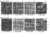
ここで、図3(a)はMg97Zn1Y2合金の押出材の結晶組織を示す顕微鏡写真であり、図3(b)はMg97Zn1Y2合金の300℃、1時間の焼きなまし材の結晶組織を示す顕微鏡写真であり、図3(c)はMg97Zn1Y2合金の400℃、1時間の焼きなまし材の結晶組織を示す顕微鏡写真であり、図3(d)はMg97Zn1Y2合金の500℃、1時間の焼きなまし材の結晶組織を示す顕微鏡写真である。図3(a)~図3(d)の中で、本発明を適用したマグネシウム合金の製造方法によって得られたマグネシウム合金は、図3(c)及び図3(d)であるが、これらマグネシウム合金1は、その合金組織中に、LPSO2とαMg相3とを有している。なお、図3(a)~図3(d)で示す顕微鏡写真において、黒色で表されている箇所がLPSOであり、粒状に見える箇所がαMg相である。
<Mg96Zn2Y2合金の場合>
鋳造工程によって形成される鋳造材がMg96Zn2Y2合金の場合には、熱処理工程によってαMg相の結晶粒径が3μm~10μmとなる様に組織制御する。具体的には、350℃以上500℃以下の温度範囲内で、かつ、0.5時間以上10時間以下の時間範囲内で熱処理を施すことによって、αMg相の結晶粒径が3μm~10μmとなる様に組織制御する。一例としては、400℃で1時間の熱処理を行うことで3μmの結晶粒径を得ることができ、500℃で1時間の熱処理を行うことで10μmの結晶粒径を得ることができる。
鋳造工程によって形成される鋳造材がMg96Zn2Y2合金の場合には、熱処理工程によってαMg相の結晶粒径が3μm~10μmとなる様に組織制御する。具体的には、350℃以上500℃以下の温度範囲内で、かつ、0.5時間以上10時間以下の時間範囲内で熱処理を施すことによって、αMg相の結晶粒径が3μm~10μmとなる様に組織制御する。一例としては、400℃で1時間の熱処理を行うことで3μmの結晶粒径を得ることができ、500℃で1時間の熱処理を行うことで10μmの結晶粒径を得ることができる。
なお、αMg相の結晶粒径を3μm~10μmに組織制御しているのは、Mg96Zn2Y2合金の場合には、こうした範囲内に組織制御することによって、概ね300MPa以上の引張強度と概ね10%以上の伸びの双方を実現することができるからである(図5(b)参照。)。
ここで、図3(e)はMg96Zn2Y2合金の押出材の結晶組織を示す顕微鏡写真であり、図3(f)はMg96Zn2Y2合金の300℃、1時間の焼きなまし材の結晶組織を示す顕微鏡写真であり、図3(g)はMg96Zn2Y2合金の400℃、1時間の焼きなまし材の結晶組織を示す顕微鏡写真であり、図3(h)はMg96Zn2Y2合金の500℃、1時間の焼きなまし材の結晶組織を示す顕微鏡写真である。図3(e)~図3(h)の中で、本発明を適用したマグネシウム合金の製造方法によって得られたマグネシウム合金は、図3(g)及び図3(h)であるが、これらマグネシウム合金1は、その合金組織中に、LPSO2とαMg相3とを有している。なお、図3(e)~図3(h)で示す顕微鏡写真において、黒色で表されている箇所がLPSOであり、粒状に見える箇所がαMg相である。
また、Mg96Zn2Y2合金を鋳造した場合には、鋳造時点で0.2μm~2.0μm程度の金属間化合物Mg3Zn3Y2を形成していることが分かった。ここで、図4(a)はMg96Zn2Y2合金の400℃、1時間の焼きなまし材の結晶組織を示す顕微鏡写真であり、図4(b)はMg96Zn2Y2合金の450℃、1時間の焼きなまし材の結晶組織を示す顕微鏡写真であり、図4(c)はMg96Zn2Y2合金の500℃、1時間の焼きなまし材の結晶組織を示す顕微鏡写真であるが、金属間化合物Mg3Zn3Y2を形成していることが分かる。なお、図4(a)~図4(c)で示す顕微鏡写真において、符号eで示す箇所が金属間化合物Mg3Zn3Y2である。
ところで、図5(a)及び図5(b)のグラフからも明らかな様に、鋳造工程によって形成される鋳造材がMg97Zn1Y2合金の場合、Mg96Zn2Y2合金の場合の双方において、400℃以上の温度で熱処理(具体的には、焼きなまし処理)を施した場合には、概ね300MPa以上の引張強度を実現しつつ、概ね12%以上の伸びを実現することができるマグネシウム合金を得ることができる。また、450℃以上の温度で熱処理(具体的には、焼きなまし処理)を施した場合には、概ね300MPa以上の引張強度を実現しつつ、概ね18%以上の伸びを実現することができるマグネシウム合金を得ることができる。
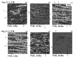
ここで、図6(a)はMg96Zn2Y2合金の400℃、1時間の焼きなまし材の結晶組織を示す顕微鏡写真であるが、図6(a)で示す顕微鏡写真からLPSOがαMg相粒内に析出していることが分かる。また、図6(b)はMg96Zn2Y2合金の425℃、1時間の焼きなまし材の結晶組織を示す顕微鏡写真であるが、図6(b)で示す顕微鏡写真からLPSOがαMg相粒内に析出していることが図6(a)よりも明確に分かる。次に、図6(c)はMg96Zn2Y2合金の450℃、1時間の焼きなまし材の結晶組織を示す顕微鏡写真であるが、図6(c)で示す顕微鏡写真から針状若しくは板状のLPSOがαMg相の粒界若しくは粒内若しくはその両方に析出し始めていることが分かる。続いて、図6(d)はMg96Zn2Y2合金の475℃、1時間の焼きなまし材の結晶組織を示す顕微鏡写真であるが、図6(d)で示す顕微鏡写真からαMg相の粒界若しくは粒内若しくはその両方で針状若しくは板状のLPSOが成長し、また、針状若しくは板状のLPSO同士が合体していることが分かる。更に、図6(e)はMg96Zn2Y2合金の500℃、1時間の焼きなまし材の結晶組織を示す顕微鏡写真であるが、図6(e)で示す顕微鏡写真からαMg相の粒界若しくは粒内若しくはその両方で針状若しくは板状のLPSOが更に成長していることが分かる。なお、図6(a)~図6(e)で示す顕微鏡写真において、黒色で表されている箇所がLPSOであり、粒状に見える箇所がαMg相である。
この様に、400℃以上の温度で熱処理(具体的には、焼きなまし処理)を施すことにより、LPSO内に含まれていた2H構造を有するマグネシウム相が消失して安定組織であるLPSOが現出する結果となる。従って、上述の様に、概ね300MPa以上の引張強度を実現しつつ、概ね12%以上の伸びを実現することができるマグネシウム合金を得ることができるのである。
更に、450℃以上の温度で熱処理(具体的には、焼きなまし処理)を施すことにより、現出したLPSOが針状組織若しくは板状組織を呈するために、押出加工材に比べてキンク帯の先鋭化が生じると共にLPSOが微細分散する結果となる。従って、上述の様に、概ね300MPa以上の引張強度を実現しつつ、概ね18%以上の伸びを実現することができるマグネシウム合金を得ることができるのである。
なお、図7(a)はMg97Zn1Y2合金の500℃、1時間の焼きなまし材の結晶組織を示す顕微鏡写真であり、図7(b)はMg97Zn1Y2合金の500℃、5時間の焼きなまし材の結晶組織を示す顕微鏡写真であり、図7(c)はMg97Zn1Y2合金の500℃、10時間の焼きなまし材の結晶組織を示す顕微鏡写真であるが、図7(a)で示す結晶組織も図7(c)で示す結晶組織も、結晶粒径において大差はなく、本発明を適用したマグネシウム合金であるMg97Zn1Y2合金が熱的安定性に優れていることが分かる。なお、マグネシウム合金の再結晶温度が300℃程度であることに鑑みると、通常のマグネシウム合金の場合には、高温で長時間の熱処理を施した場合には、結晶粒径が成長することで伸びは改善するものの、引張強度が極端に低下してしまう。なお、図7(a)~図7(c)で示す顕微鏡写真において、黒色で表されている箇所がLPSOであり、粒状に見える箇所がαMg相である。
同様に、図7(d)はMg96Zn2Y2合金の500℃、1時間の焼きなまし材の結晶組織を示す顕微鏡写真であり、図7(e)はMg96Zn2Y2合金の500℃、5時間の焼きなまし材の結晶組織を示す顕微鏡写真であり、図7(f)はMg96Zn2Y2合金の500℃、10時間の焼きなまし材の結晶組織を示す顕微鏡写真であるが、図7(d)で示す結晶組織も図7(f)で示す結晶組織も、結晶粒径において大差はなく、本発明を適用したマグネシウム合金であるMg96Zn2Y2合金は熱的安定性に優れていることが分かる。なお、図7(d)~図7(f)で示す顕微鏡写真において、黒色で表されている箇所がLPSOであり、粒状に見える箇所がαMg相である。
また、図8(a)はMg96Zn2Y2合金の400℃、1時間の焼きなまし材の結晶組織を示す顕微鏡写真であり、図8(a)で示す顕微鏡写真においては、LPSOの結晶方位の向きやαMg相の結晶方位の向きに規則性はなく、結晶方向の向きは乱れた状態であることが分かる。一方、図8(b)はMg96Zn2Y2合金の500℃、1時間の焼きなまし材の結晶組織を示す顕微鏡写真であり、図8(b)で示す顕微鏡写真においては、同一のLPSO内の結晶方位の向きは全て同一であり、また、任意のLPSO内の結晶方位の向きは、隣接するいずれかのαMg相の結晶方位と同一であることが分かる。なお、任意のLPSO内の結晶方位の向きが、隣接するαMg相の双方と同一となることもあり得る。また、LPSOの現出箇所はαMg相の結晶粒界若しくは結晶粒内であって、結晶粒界と結晶粒内に現出する場合もある。
以下、本発明の実施例について説明する。なお、ここで示す実施例は一例であり本発明を限定するものではない。
[実施例(1)]
先ず、本発明の実施例(1)のマグネシウム合金の製造方法として、Znを1原子%、Yを2原子%とし、残部をMgと不可避的不純物のMg-Zn-Y合金をアルゴンガス雰囲気中の高周波溶解炉内で溶解を行った。次に、加熱溶解した材料を金型で鋳造し、φ29mm×L60mmのインゴット(鋳造材)を作製した。続いて、押出温度350℃、押出比10、押出速度2.5mm/sの条件で塑性加工(押出加工)を行い、その後100℃~500℃の熱処理温度にて1時間の熱処理(焼きなまし)を行ったものを作製した。
先ず、本発明の実施例(1)のマグネシウム合金の製造方法として、Znを1原子%、Yを2原子%とし、残部をMgと不可避的不純物のMg-Zn-Y合金をアルゴンガス雰囲気中の高周波溶解炉内で溶解を行った。次に、加熱溶解した材料を金型で鋳造し、φ29mm×L60mmのインゴット(鋳造材)を作製した。続いて、押出温度350℃、押出比10、押出速度2.5mm/sの条件で塑性加工(押出加工)を行い、その後100℃~500℃の熱処理温度にて1時間の熱処理(焼きなまし)を行ったものを作製した。
この様にして得られたそれぞれのマグネシウム合金を室温にて引張試験を行い、機械的特性を評価した結果を図5(a)に示す。
図5(a)から明らかな様に、本発明の実施例(1)のマグネシウム合金の製造方法で得られるMg97Zn1Y2合金は、350℃以上の温度で焼きなました場合には概ね300MPa以上の引張強度を実現すると共に概ね10%以上の伸びを実現することができる。更に、図5(a)から明らかな様に、本発明の実施例(1)のマグネシウム合金の製造方法で得られるMg97Zn1Y2合金は、400℃以上の温度で焼きなました場合には概ね300MPa以上の引張強度を実現すると共に概ね12%以上の伸びを実現し、450℃以上の温度で焼きなました場合には概ね300MPa以上の引張強度を実現すると共に概ね18%以上の伸びを実現することができる。
[実施例(2)]
また、本発明の実施例(2)のマグネシウム合金の製造方法として、Znを2原子%、Yを2原子%とし、残部をMgと不可避的不純物のMg-Zn-Y合金をアルゴンガス雰囲気中の高周波溶解炉内で溶解を行った。次に、加熱溶解した材料を金型で鋳造し、φ29mm×L60mmのインゴット(鋳造材)を作製した。続いて、押出温度350℃、押出比10、押出速度2.5mm/sの条件で塑性加工(押出加工)を行い、その後100℃~500℃の熱処理温度にて1時間の熱処理(焼きなまし)を行ったものを作製した。
また、本発明の実施例(2)のマグネシウム合金の製造方法として、Znを2原子%、Yを2原子%とし、残部をMgと不可避的不純物のMg-Zn-Y合金をアルゴンガス雰囲気中の高周波溶解炉内で溶解を行った。次に、加熱溶解した材料を金型で鋳造し、φ29mm×L60mmのインゴット(鋳造材)を作製した。続いて、押出温度350℃、押出比10、押出速度2.5mm/sの条件で塑性加工(押出加工)を行い、その後100℃~500℃の熱処理温度にて1時間の熱処理(焼きなまし)を行ったものを作製した。
この様にして得られたそれぞれのマグネシウム合金を室温にて引張試験を行い、機械的特性を評価した結果を図5(b)に示す。
図5(b)から明らかな様に、本発明の実施例(2)のマグネシウム合金の製造方法で得られるMg96Zn2Y2合金は、350℃以上の温度で焼きなました場合には概ね300MPa以上の引張強度を実現すると共に概ね10%以上の伸びを実現することができる。更に、図5(b)から明らかな様に、本発明の実施例(2)のマグネシウム合金の製造方法で得られるMg96Zn2Y2合金は、400℃以上の温度で焼きなました場合には概ね300MPa以上の引張強度を実現すると共に概ね12%以上の伸びを実現し、450℃以上の温度で焼きなました場合には概ね300MPa以上の引張強度を実現すると共に概ね18%以上の伸びを実現することができる。
1 マグネシウム合金
2 LPSO
3 αMg相
2 LPSO
3 αMg相
Claims (11)
- 必須成分としてZnとYとを含有し、残部がMgと不可避的不純物からなるMg-Zn-Y系合金から構成されるマグネシウム合金であって、
Mg-Zn-Y系合金の合金組織中に、αMg相と長周期積層構造相とを有し、
該長周期積層構造相の少なくとも一部が前記αMg相とラメラ状に存在すると共に、該ラメラ状に存在する組織の少なくとも一部が湾曲または屈曲しており、
更に、湾曲または屈曲している部分でαMg相と長周期積層構造相の不連続界面が形成され、若しくは、湾曲または屈曲している部分でαMg相と長周期積層構造相の粒界が形成されている
マグネシウム合金。 - 必須成分としてZnとYとを含有し、残部がMgと不可避的不純物からなるMg-Zn-Y系合金から構成されるマグネシウム合金であって、
Mg-Zn-Y系合金の合金組織中に、針状若しくは板状の長周期積層構造相を有する
マグネシウム合金。 - 前記長周期積層構造相が針状若しくは板状であり、同長周期積層構造相が有するキンク帯の先鋭化が生じると共に長周期積層構造相が微細分散した
請求項1に記載のマグネシウム合金。 - 前記αMg相の結晶粒界若しくは結晶粒内またはその両方に長周期積層構造相を有しており、前記αMgの結晶粒内若しくは前記αMg相の結晶粒界の少なくとも一方に、長周期積層構造相を有する
請求項1、請求項2若しくは請求項3に記載のマグネシウム合金。 - 前記αMg相の結晶粒内若しくは前記αMg相の結晶粒界の少なくとも一方に、針状若しくは板状の長周期積層構造相を有する
請求項1、請求項2若しくは請求項3に記載のマグネシウム合金。 - 必須成分としてZnとYを含有し、残部がMgと不可避的不純物とからなるMg-Zn-Y系合金を鋳造して、長周期積層構造相とαMg相とを含む鋳造材を形成する鋳造工程と、
前記鋳造材に塑性加工を行う塑性加工工程と、
該塑性加工工程により塑性加工を施した前記鋳造材に熱処理を施す熱処理工程とを備えるマグネシウム合金の製造方法であって、
前記熱処理工程は、350℃以上500℃以下の温度範囲内で、かつ、0.5時間以上10時間以下の時間範囲内で行う
マグネシウム合金の製造方法。 - 前記熱処理工程は、400℃以上500℃以下の温度範囲内で、かつ、0.5時間以上10時間以下の時間範囲内で行う
請求項6に記載のマグネシウム合金の製造方法。 - 前記熱処理工程は、450℃以上500℃以下の温度範囲内で、かつ、0.5時間以上10時間以下の時間範囲内で行う
請求項6に記載のマグネシウム合金の製造方法。 - 前記鋳造工程によりMg97Zn1Y2合金よりなる鋳造材を形成すると共に、
前記熱処理工程によりαMg相の結晶粒径を7μm以上15μm以下に制御する
請求項6に記載のマグネシウム合金の製造方法。 - 前記鋳造工程によりMg96Zn2Y2合金よりなる鋳造材を形成すると共に、
前記熱処理工程によりαMg相の結晶粒径を3μm以上10μm以下に制御する
請求項6に記載のマグネシウム合金の製造方法。 - 前記熱処理工程により針状若しくは板状の長周期積層構造相を現出せしめる
請求項8に記載のマグネシウム合金の製造方法。
Applications Claiming Priority (4)
| Application Number | Priority Date | Filing Date | Title |
|---|---|---|---|
| JP2008265830A JP2010095741A (ja) | 2008-10-15 | 2008-10-15 | マグネシウム合金の製造方法 |
| JP2008-265830 | 2008-10-15 | ||
| JP2008-270139 | 2008-10-20 | ||
| JP2008270139A JP2010095787A (ja) | 2008-10-20 | 2008-10-20 | マグネシウム合金及びその製造方法 |
Publications (1)
| Publication Number | Publication Date |
|---|---|
| WO2010044320A1 true WO2010044320A1 (ja) | 2010-04-22 |
Family
ID=42106487
Family Applications (1)
| Application Number | Title | Priority Date | Filing Date |
|---|---|---|---|
| PCT/JP2009/065701 Ceased WO2010044320A1 (ja) | 2008-10-15 | 2009-09-09 | マグネシウム合金及びその製造方法 |
Country Status (1)
| Country | Link |
|---|---|
| WO (1) | WO2010044320A1 (ja) |
Cited By (2)
| Publication number | Priority date | Publication date | Assignee | Title |
|---|---|---|---|---|
| WO2011125887A1 (ja) * | 2010-03-31 | 2011-10-13 | 国立大学法人 熊本大学 | マグネシウム合金板材 |
| CN107312989A (zh) * | 2017-06-07 | 2017-11-03 | 河海大学 | 一种含有lpso结构的纳米晶‑超细晶梯度镁合金的制备方法 |
Citations (5)
| Publication number | Priority date | Publication date | Assignee | Title |
|---|---|---|---|---|
| JP2005113235A (ja) * | 2003-10-09 | 2005-04-28 | Toyota Motor Corp | 高強度マグネシウム合金およびその製造方法 |
| WO2005052203A1 (ja) * | 2003-11-26 | 2005-06-09 | Yoshihito Kawamura | 高強度高靭性マグネシウム合金及びその製造方法 |
| JP2005213535A (ja) * | 2004-01-27 | 2005-08-11 | National Institute Of Advanced Industrial & Technology | 高性能マグネシウム合金及びその製造方法 |
| JP2008075183A (ja) * | 2004-09-30 | 2008-04-03 | Yoshihito Kawamura | 高強度高靭性金属及びその製造方法 |
| JP2008150704A (ja) * | 2006-11-21 | 2008-07-03 | Kobe Steel Ltd | マグネシウム合金材およびその製造方法 |
-
2009
- 2009-09-09 WO PCT/JP2009/065701 patent/WO2010044320A1/ja not_active Ceased
Patent Citations (5)
| Publication number | Priority date | Publication date | Assignee | Title |
|---|---|---|---|---|
| JP2005113235A (ja) * | 2003-10-09 | 2005-04-28 | Toyota Motor Corp | 高強度マグネシウム合金およびその製造方法 |
| WO2005052203A1 (ja) * | 2003-11-26 | 2005-06-09 | Yoshihito Kawamura | 高強度高靭性マグネシウム合金及びその製造方法 |
| JP2005213535A (ja) * | 2004-01-27 | 2005-08-11 | National Institute Of Advanced Industrial & Technology | 高性能マグネシウム合金及びその製造方法 |
| JP2008075183A (ja) * | 2004-09-30 | 2008-04-03 | Yoshihito Kawamura | 高強度高靭性金属及びその製造方法 |
| JP2008150704A (ja) * | 2006-11-21 | 2008-07-03 | Kobe Steel Ltd | マグネシウム合金材およびその製造方法 |
Non-Patent Citations (1)
| Title |
|---|
| MASASHI NODA ET AL.: "Choshuki Sekiso Kozogata Mg-Zn-Y Gokin no Kikaiteki Tokusei ni Oyobosu Kessho Soshiki no Eikyo", ABSTRACTS OF THE JAPAN INSTITUTE OF METALS, 26 March 2008 (2008-03-26), pages 371 * |
Cited By (8)
| Publication number | Priority date | Publication date | Assignee | Title |
|---|---|---|---|---|
| WO2011125887A1 (ja) * | 2010-03-31 | 2011-10-13 | 国立大学法人 熊本大学 | マグネシウム合金板材 |
| CN102822366A (zh) * | 2010-03-31 | 2012-12-12 | 国立大学法人熊本大学 | 镁合金板材 |
| JP5581505B2 (ja) * | 2010-03-31 | 2014-09-03 | 国立大学法人 熊本大学 | マグネシウム合金板材 |
| CN104762543A (zh) * | 2010-03-31 | 2015-07-08 | 国立大学法人熊本大学 | 镁合金板材的制造方法 |
| EP2557188A4 (en) * | 2010-03-31 | 2017-04-05 | National University Corporation Kumamoto University | Magnesium alloy sheet |
| US10260130B2 (en) | 2010-03-31 | 2019-04-16 | National University Corporation Kumamoto University | Magnesium alloy sheet material |
| CN107312989A (zh) * | 2017-06-07 | 2017-11-03 | 河海大学 | 一种含有lpso结构的纳米晶‑超细晶梯度镁合金的制备方法 |
| CN107312989B (zh) * | 2017-06-07 | 2018-09-04 | 河海大学 | 一种含有lpso结构的纳米晶-超细晶梯度镁合金的制备方法 |
Similar Documents
| Publication | Publication Date | Title |
|---|---|---|
| JP5024705B2 (ja) | マグネシウム合金材およびその製造方法 | |
| JP5467294B2 (ja) | 易成形性マグネシウム合金板材及びその作製方法 | |
| JP5565617B2 (ja) | マグネシウム合金材の製造方法及びマグネシウム合金材 | |
| US10260130B2 (en) | Magnesium alloy sheet material | |
| KR20220063628A (ko) | Al-Mg-Si계 알루미늄 합금 및 그 제조방법 | |
| JP5458289B2 (ja) | マグネシウム合金 | |
| WO2012133651A1 (ja) | 銅合金および銅合金の製造方法 | |
| JP5531274B2 (ja) | 高強度マグネシウム合金 | |
| JP4958267B2 (ja) | マグネシウム合金材およびその製造方法 | |
| JP5196543B2 (ja) | マグネシウム合金材およびその製造方法 | |
| WO2010044320A1 (ja) | マグネシウム合金及びその製造方法 | |
| JP5412666B2 (ja) | マグネシウム合金及びその製造方法 | |
| JP5458290B2 (ja) | マグネシウム合金 | |
| JP6726058B2 (ja) | Al合金鋳造物の製造方法 | |
| JP2010095787A (ja) | マグネシウム合金及びその製造方法 | |
| JP2010095741A (ja) | マグネシウム合金の製造方法 | |
| JP5131728B2 (ja) | 高強力Ti−Ni−Cu形状記憶合金とその製造方法 | |
| JP6035645B2 (ja) | マグネシウム合金材の製造方法 | |
| JP5252722B2 (ja) | 高強度・高導電性銅合金及びその製造方法 | |
| JP6185799B2 (ja) | Cu−Ti系銅合金および製造方法 | |
| KR102578988B1 (ko) | 계층적 NiAl/Ni2TiAl 석출물을 포함하는 고엔트로피 합금 및 이의 제조방법 | |
| KR101573709B1 (ko) | 타이타늄 합금을 이용한 비정질 복합재료와 그 제조방법 | |
| JP2018168427A (ja) | マグネシウム合金及びその製造方法 | |
| JP2023088899A (ja) | マグネシウム合金の製造方法及びマグネシウム合金 | |
| JP2007051355A (ja) | Co3Ti薄板の製造方法、Co3Ti薄板 |
Legal Events
| Date | Code | Title | Description |
|---|---|---|---|
| 121 | Ep: the epo has been informed by wipo that ep was designated in this application |
Ref document number: 09820498 Country of ref document: EP Kind code of ref document: A1 |
|
| DPE1 | Request for preliminary examination filed after expiration of 19th month from priority date (pct application filed from 20040101) | ||
| NENP | Non-entry into the national phase |
Ref country code: DE |
|
| 122 | Ep: pct application non-entry in european phase |
Ref document number: 09820498 Country of ref document: EP Kind code of ref document: A1 |