WO2010021077A1 - 自動変速機 - Google Patents
自動変速機 Download PDFInfo
- Publication number
- WO2010021077A1 WO2010021077A1 PCT/JP2009/003172 JP2009003172W WO2010021077A1 WO 2010021077 A1 WO2010021077 A1 WO 2010021077A1 JP 2009003172 W JP2009003172 W JP 2009003172W WO 2010021077 A1 WO2010021077 A1 WO 2010021077A1
- Authority
- WO
- WIPO (PCT)
- Prior art keywords
- clutch
- drum
- piston
- oil chamber
- oil
- Prior art date
- Legal status (The legal status is an assumption and is not a legal conclusion. Google has not performed a legal analysis and makes no representation as to the accuracy of the status listed.)
- Ceased
Links
Images


Classifications
-
- F—MECHANICAL ENGINEERING; LIGHTING; HEATING; WEAPONS; BLASTING
- F16—ENGINEERING ELEMENTS AND UNITS; GENERAL MEASURES FOR PRODUCING AND MAINTAINING EFFECTIVE FUNCTIONING OF MACHINES OR INSTALLATIONS; THERMAL INSULATION IN GENERAL
- F16D—COUPLINGS FOR TRANSMITTING ROTATION; CLUTCHES; BRAKES
- F16D25/00—Fluid-actuated clutches
- F16D25/06—Fluid-actuated clutches in which the fluid actuates a piston incorporated in, i.e. rotating with the clutch
- F16D25/062—Fluid-actuated clutches in which the fluid actuates a piston incorporated in, i.e. rotating with the clutch the clutch having friction surfaces
- F16D25/063—Fluid-actuated clutches in which the fluid actuates a piston incorporated in, i.e. rotating with the clutch the clutch having friction surfaces with clutch members exclusively moving axially
- F16D25/0635—Fluid-actuated clutches in which the fluid actuates a piston incorporated in, i.e. rotating with the clutch the clutch having friction surfaces with clutch members exclusively moving axially with flat friction surfaces, e.g. discs
- F16D25/0638—Fluid-actuated clutches in which the fluid actuates a piston incorporated in, i.e. rotating with the clutch the clutch having friction surfaces with clutch members exclusively moving axially with flat friction surfaces, e.g. discs with more than two discs, e.g. multiple lamellae
-
- F—MECHANICAL ENGINEERING; LIGHTING; HEATING; WEAPONS; BLASTING
- F16—ENGINEERING ELEMENTS AND UNITS; GENERAL MEASURES FOR PRODUCING AND MAINTAINING EFFECTIVE FUNCTIONING OF MACHINES OR INSTALLATIONS; THERMAL INSULATION IN GENERAL
- F16D—COUPLINGS FOR TRANSMITTING ROTATION; CLUTCHES; BRAKES
- F16D25/00—Fluid-actuated clutches
- F16D25/10—Clutch systems with a plurality of fluid-actuated clutches
-
- F—MECHANICAL ENGINEERING; LIGHTING; HEATING; WEAPONS; BLASTING
- F16—ENGINEERING ELEMENTS AND UNITS; GENERAL MEASURES FOR PRODUCING AND MAINTAINING EFFECTIVE FUNCTIONING OF MACHINES OR INSTALLATIONS; THERMAL INSULATION IN GENERAL
- F16H—GEARING
- F16H3/00—Toothed gearings for conveying rotary motion with variable gear ratio or for reversing rotary motion
- F16H3/44—Toothed gearings for conveying rotary motion with variable gear ratio or for reversing rotary motion using gears having orbital motion
- F16H3/62—Gearings having three or more central gears
- F16H3/66—Gearings having three or more central gears composed of a number of gear trains without drive passing from one train to another
- F16H3/663—Gearings having three or more central gears composed of a number of gear trains without drive passing from one train to another with conveying rotary motion between axially spaced orbital gears, e.g. a stepped orbital gear or Ravigneaux
-
- F—MECHANICAL ENGINEERING; LIGHTING; HEATING; WEAPONS; BLASTING
- F16—ENGINEERING ELEMENTS AND UNITS; GENERAL MEASURES FOR PRODUCING AND MAINTAINING EFFECTIVE FUNCTIONING OF MACHINES OR INSTALLATIONS; THERMAL INSULATION IN GENERAL
- F16H—GEARING
- F16H3/00—Toothed gearings for conveying rotary motion with variable gear ratio or for reversing rotary motion
- F16H3/44—Toothed gearings for conveying rotary motion with variable gear ratio or for reversing rotary motion using gears having orbital motion
- F16H3/62—Gearings having three or more central gears
- F16H3/66—Gearings having three or more central gears composed of a number of gear trains without drive passing from one train to another
- F16H3/666—Gearings having three or more central gears composed of a number of gear trains without drive passing from one train to another with intermeshing orbital gears
-
- F—MECHANICAL ENGINEERING; LIGHTING; HEATING; WEAPONS; BLASTING
- F16—ENGINEERING ELEMENTS AND UNITS; GENERAL MEASURES FOR PRODUCING AND MAINTAINING EFFECTIVE FUNCTIONING OF MACHINES OR INSTALLATIONS; THERMAL INSULATION IN GENERAL
- F16H—GEARING
- F16H57/00—General details of gearing
- F16H57/08—General details of gearing of gearings with members having orbital motion
-
- F—MECHANICAL ENGINEERING; LIGHTING; HEATING; WEAPONS; BLASTING
- F16—ENGINEERING ELEMENTS AND UNITS; GENERAL MEASURES FOR PRODUCING AND MAINTAINING EFFECTIVE FUNCTIONING OF MACHINES OR INSTALLATIONS; THERMAL INSULATION IN GENERAL
- F16H—GEARING
- F16H57/00—General details of gearing
- F16H57/08—General details of gearing of gearings with members having orbital motion
- F16H2057/087—Arrangement and support of friction devices in planetary gearings, e.g. support of clutch drums, stacked arrangements of friction devices
-
- F—MECHANICAL ENGINEERING; LIGHTING; HEATING; WEAPONS; BLASTING
- F16—ENGINEERING ELEMENTS AND UNITS; GENERAL MEASURES FOR PRODUCING AND MAINTAINING EFFECTIVE FUNCTIONING OF MACHINES OR INSTALLATIONS; THERMAL INSULATION IN GENERAL
- F16H—GEARING
- F16H2200/00—Transmissions for multiple ratios
- F16H2200/003—Transmissions for multiple ratios characterised by the number of forward speeds
- F16H2200/006—Transmissions for multiple ratios characterised by the number of forward speeds the gear ratios comprising eight forward speeds
-
- F—MECHANICAL ENGINEERING; LIGHTING; HEATING; WEAPONS; BLASTING
- F16—ENGINEERING ELEMENTS AND UNITS; GENERAL MEASURES FOR PRODUCING AND MAINTAINING EFFECTIVE FUNCTIONING OF MACHINES OR INSTALLATIONS; THERMAL INSULATION IN GENERAL
- F16H—GEARING
- F16H2200/00—Transmissions for multiple ratios
- F16H2200/20—Transmissions using gears with orbital motion
- F16H2200/2002—Transmissions using gears with orbital motion characterised by the number of sets of orbital gears
- F16H2200/2007—Transmissions using gears with orbital motion characterised by the number of sets of orbital gears with two sets of orbital gears
-
- F—MECHANICAL ENGINEERING; LIGHTING; HEATING; WEAPONS; BLASTING
- F16—ENGINEERING ELEMENTS AND UNITS; GENERAL MEASURES FOR PRODUCING AND MAINTAINING EFFECTIVE FUNCTIONING OF MACHINES OR INSTALLATIONS; THERMAL INSULATION IN GENERAL
- F16H—GEARING
- F16H2200/00—Transmissions for multiple ratios
- F16H2200/20—Transmissions using gears with orbital motion
- F16H2200/202—Transmissions using gears with orbital motion characterised by the type of Ravigneaux set
- F16H2200/2023—Transmissions using gears with orbital motion characterised by the type of Ravigneaux set using a Ravigneaux set with 4 connections
-
- F—MECHANICAL ENGINEERING; LIGHTING; HEATING; WEAPONS; BLASTING
- F16—ENGINEERING ELEMENTS AND UNITS; GENERAL MEASURES FOR PRODUCING AND MAINTAINING EFFECTIVE FUNCTIONING OF MACHINES OR INSTALLATIONS; THERMAL INSULATION IN GENERAL
- F16H—GEARING
- F16H2200/00—Transmissions for multiple ratios
- F16H2200/20—Transmissions using gears with orbital motion
- F16H2200/203—Transmissions using gears with orbital motion characterised by the engaging friction means not of the freewheel type, e.g. friction clutches or brakes
- F16H2200/2048—Transmissions using gears with orbital motion characterised by the engaging friction means not of the freewheel type, e.g. friction clutches or brakes with seven engaging means
-
- F—MECHANICAL ENGINEERING; LIGHTING; HEATING; WEAPONS; BLASTING
- F16—ENGINEERING ELEMENTS AND UNITS; GENERAL MEASURES FOR PRODUCING AND MAINTAINING EFFECTIVE FUNCTIONING OF MACHINES OR INSTALLATIONS; THERMAL INSULATION IN GENERAL
- F16H—GEARING
- F16H2200/00—Transmissions for multiple ratios
- F16H2200/20—Transmissions using gears with orbital motion
- F16H2200/2097—Transmissions using gears with orbital motion comprising an orbital gear set member permanently connected to the housing, e.g. a sun wheel permanently connected to the housing
Definitions
- the present invention relates to an automatic transmission mounted on, for example, a vehicle or the like, and more particularly to an automatic transmission including two clutches that are overlapped in the axial direction and arranged at different positions in the radial direction.
- two clutches that have one input / output member in common and the other in the other are overlapped in the axial direction and arranged at different radial positions to achieve compactness, particularly in the axial direction.
- a transmission has been proposed (see, for example, Japanese Patent Laid-Open No. 7-269665).
- a multi-plate friction plate, a hydraulic servo for connecting / disconnecting these friction plates, and a cancel oil chamber for canceling the centrifugal hydraulic pressure of the piston operating hydraulic chamber are arranged to overlap each other in the axial direction. ing.
- the cancellation oil chamber on the inner diameter side is directly supplied with oil through an oil hole formed in the boss portion of the clutch drum.
- the oil in the cancel oil chamber on the inner diameter side is supplied through an oil hole provided in the piston and clutch drum of the inner diameter side clutch. Disclosure of the invention
- These two clutches have a two-story structure that overlaps in the axial direction, and the oil provided in the piston and clutch drum in order to supply oil from the cancel oil chamber on the inner diameter side to the cancel oil chamber on the outer diameter side.
- the oil is supplied to the cancel oil chamber on the outer diameter side through the hole, in order to form this oil passage, it is necessary to provide two O-rings on the piston so that the oil does not leak.
- these O-rings had to be arranged at regular intervals in the axial direction so that the O-rings provided on the sliding piston did not reach the oil holes.
- the present invention provides a plate member between the piston of the inner diameter side clutch and the clutch drum, and cancels the outer diameter side clutch via an oil passage formed between the plate member and the clutch drum. It aims at providing the automatic transmission which solved the subject mentioned above by supplying oil to an oil chamber.
- the present invention includes first and second clutches (C4, C3) that overlap in the direction of the shaft (7) and are arranged at different positions in the radial direction, and these first clutch (C4) and second clutch ( C3) includes a clutch drum (26, 25), a piston (29, 36) contained in the clutch drum (26, 25), and a plurality of friction plates engaged with the clutch drum (26, 25). (21, 19), the hydraulic oil chamber (33, 40) of the piston (29, 36), and the hydraulic oil chamber (33, 40) across the piston (29, 36).
- a plate member (32) that forms a cylinder portion of the hydraulic oil chamber (33) is provided between the piston (29) of the first clutch (C4) located on the inner diameter side and the clutch drum (26).
- An oil passage is formed between the clutch drum (26) and the plate member (32) for supplying oil to the cancel oil chamber (41) of the second clutch (C3) located on the outer diameter side. It is in the automatic transmission characterized by this.
- the first clutch and the second clutch overlap in the axial direction and are arranged at different positions in the radial direction, and a plate member is provided between the piston of the first clutch located on the inner diameter side and the clutch drum.
- a member that moves relatively, such as a piston, by supplying oil to the cancel oil chamber of the second clutch located on the outer diameter side through an oil passage between the plate member that is the fixed member and the clutch drum Compared with the formation of the oil passage, the number of seal members is reduced, and it is not necessary to arrange the seal members with a sufficient margin in the axial direction in consideration of relative movement of these seal members.
- the clutch and the automatic transmission can be shortened in the axial direction.
- the clutch drum (26) of the first clutch (C4) includes a boss portion (27) and a flange portion (26a) extending from the boss portion (27) in the circumferential direction. ), A cylindrical portion (26b) extending in the axial direction from the flange portion (26a), and a drum portion (26c) on which the friction plate (21a) is spline-engaged on the tip side of the cylindrical portion (26b).
- the piston (36) and the cancel plate (37) constituting the cancel oil chamber (41) of the second clutch (C3) are disposed on the outer periphery of the cylindrical portion (26b).
- the cylindrical portion of the clutch drum of the first clutch is provided with the cancel oil chamber of the second clutch on the outer periphery thereof, so that the first clutch and the second clutch are arranged adjacent to each other, and the second clutch easily An oil path to the cancel oil chamber can be formed.
- the drum portion (26c) is positioned on the outer diameter side compared to the cylindrical portion (26b), and the cylindrical portion ( 26b) with a step,
- the cancel plate (37) of the second clutch (C3) is abutted and locked to the step between the drum portion (26c) and the cylindrical portion (26b).
- the clutch drum of the first clutch has the drum portion disposed on the outer diameter side of the cylindrical portion, and a step is formed between the drum portion and the cylindrical portion, and the cancel plate of the second clutch is formed on the step.
- a regulating member such as a snap ring for locking the cancel plate can be made unnecessary, and the axial direction of the clutch can be shortened accordingly.
- the drum portion (26c) and the cylindrical portion (26b) are formed separately, and the drum portion (26c) is formed. It is locked to the cylindrical part (26b) by a regulating member (50).
- the fulcrum of the moment force applied to the clutch drum is the connecting portion between the drum portion and the cylindrical portion. Therefore, the posture change of the drum portion can be reduced, and the moment force applied to the clutch drum of the first clutch can be reduced to prevent deformation of the clutch drum of the first clutch.
- the oil passage (46) includes a gap (32a) between the clutch drum (26) of the first clutch (C4) and the plate member (32), and the clutch drum (26).
- An oil hole (27d) is formed in the boss portion (27) and supplies oil to the gap (32a), and a cylindrical portion (26b) of the clutch drum (26). It has an oil hole (26d) for supplying oil to the cancel oil chamber (41) of the two clutch (C3).
- the thickness of the cylindrical portion (26b) and the flange portion (26a) is larger than the thickness of the plate member (32). Formed.
- the plate member is provided on the clutch drum of the first clutch having high rigidity, the thickness of the plate member can be reduced and the axial direction of the clutch can be shortened.
- the plate member (32) is welded to the cylindrical portion (26b) of the clutch drum (26) of the first clutch (C4).
- the plate member is welded to the cylindrical portion of the clutch drum of the first clutch, so that it is not necessary to cut the cylindrical portion to be thickened in order to place an O-ring or the like, and the rigidity of the clutch drum is kept high. Can do.
- the plate member (32) includes a first protrusion (32b) protruding toward the piston (29) and a second protrusion (32c) protruding toward the clutch drum (26). And is press-molded to have The first and second protrusions (32b, 32c) are arranged with different phases at different positions on the same diameter.
- the first and second protrusions are arranged on the plate member so that the first and second protrusions are at different positions on the same diameter, so that the plate member and the piston, which are cylinder members, can be bonded to each other with a simple press process. It is possible to prevent sticking and secure the clearance of the oil passage formed between the plate member and the flange portion.
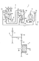
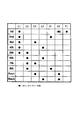
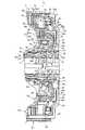
- the engagement table of the automatic transmission shown in FIG. 1 is a partial enlarged cross-sectional view showing an automatic transmission according to a first embodiment of the present invention.
- the partial expanded sectional view which shows the automatic transmission which concerns on the 2nd Embodiment of this invention.
- the partial expanded sectional view which shows the automatic transmission which concerns on the 3rd Embodiment of this invention.
- the automatic transmission according to the present invention is an automatic transmission suitable for being mounted on a vehicle of FF (front engine / front drive) type or the like, and the horizontal direction in FIGS. 1, 3 and 4 is the actual vehicle mounting. Although it corresponds to the left-right direction in the state, for convenience of explanation, the right side in the figure which is the drive source side of the engine or the like is referred to as “front side”, and the left side in the figure is referred to as “rear side”.
- an FF type automatic transmission 1 includes a case 6 including a housing case and a transmission case, and an automatic transmission 1 that can be connected to an engine (not shown) on the front side of the case 6.
- the automatic transmission 1 is provided with a torque converter 2 having a lock-up clutch 2 a, and a transmission mechanism 3, a counter shaft part 4, and a differential part 5 are arranged in a transmission case 6.
- the torque converter 2 is disposed on an axis centering on the input shaft 7 of the speed change mechanism 3 that is coaxial with the output shaft of an engine (not shown). Further, the counter shaft portion 4 is disposed on a counter shaft 12 that is on an axis parallel to the input shaft 7, and the differential portion 5 has left and right axles 15 and 15 on an axis parallel to the counter shaft 12. Arranged in a shape.
- the speed change mechanism 3 is provided with a planetary gear (deceleration planetary gear) DP on the input shaft 7 and a planetary gear unit (planetary gear set) PU on the rear side thereof.
- the planetary gear DP includes a first sun gear S1, a first carrier CR1, and a first ring gear R1, and the first carrier CR1 has a pinion P2 and a first pinion meshing with the first sun gear S1.
- This is a so-called double pinion planetary gear having pinions P1 meshing with the ring gear R1 so as to mesh with each other.
- the planetary gear unit PU has, as four rotating elements, a second sun gear S2, a third sun gear S3, a second carrier CR2, and a second ring gear R2, and the second carrier CR2
- This is a so-called Ravigneaux type planetary gear having a long pinion P3 meshing with the sun gear S3 and the second ring gear R2 and a short pinion P4 meshing with the second sun gear S2.
- the rotation of the first sun gear S1 of the planetary gear DP is fixed with respect to the case 6.
- the first carrier CR1 is connected to the input shaft 7 and is in the same rotation as the rotation of the input shaft 7 (hereinafter referred to as “input rotation”).
- 1 clutch is connected to C4.
- the first ring gear R1 is decelerated by the input rotation being decelerated by the fixed first sun gear S1 and the input first carrier CR1, and the first clutch C1 and the first clutch C1.
- the third sun gear S3 of the planetary gear unit PU is connected to the first brake B1 and can be fixed to the case 6, and is connected to the fourth clutch C4 and the third clutch C3.
- the input rotation of the first carrier CR1 can be input via the fourth clutch C4, and the reduced rotation of the first ring gear R1 can be input via the third clutch C3.
- the second sun gear S2 is connected to the first clutch C1, and the reduced rotation of the first ring gear R1 can be input.
- the second carrier CR2 is connected to the second clutch C2 to which the rotation of the input shaft 7 is input, and the input rotation can be freely input via the second clutch C2.
- the rotation in one direction with respect to the case 6 is restricted via the one-way clutch F1, and the rotation can be fixed via the second brake B2. It has become.
- the second ring gear R2 is connected to a counter gear 8 that is rotatably supported by a center support member fixed to the mission case 6.
- the counter gear 8 meshes with a large-diameter gear 11 fixed on the counter shaft 12 of the counter shaft portion 4, and the counter shaft 12 is formed on the outer peripheral surface of the counter shaft 12.
- the gear 14 of the differential portion 5 is engaged with the small-diameter gear 12a.
- the gear 14 is fixed to a differential gear 13 and is connected to the left and right axles 15 and 15 via the differential gear 13.
- the first clutch C1 and the one-way clutch F1 are engaged.
- the rotation of the first ring gear R1 that is decelerated by the fixed first sun gear S1 and the first carrier CR1 that is the input rotation is input to the second sun gear S2 via the first clutch C1.
- the rotation of the second carrier CR2 is restricted in one direction (forward rotation direction), that is, the reverse rotation of the second carrier CR2 is prevented and fixed.
- the decelerated rotation input to the second sun gear S2 is output to the second ring gear R2 via the fixed second carrier CR2, and the forward rotation as the first forward speed is output from the counter gear 8. Is done.
- the second brake B2 is locked and the second carrier CR2 is fixed to prevent forward rotation of the second carrier CR2. Maintain the speed.
- the one-way clutch F1 prevents the second carrier CR2 from rotating in the reverse direction and enables forward rotation. For example, the first forward speed when the non-travel range is switched to the travel range. The stage can be achieved smoothly by the automatic engagement of the one-way clutch F1.
- the first clutch C1 is engaged and the first brake B1 is locked.
- the rotation of the first ring gear R1 decelerated by the fixed first sun gear S1 and the first carrier CR1, which is the input rotation is input to the second sun gear S2 via the first clutch C1.
- the rotation of the third sun gear S3 is fixed by the locking of the first brake B1.
- the second carrier CR2 is decelerated and rotated at a speed lower than that of the second sun gear S2, and the decelerated rotation input to the second sun gear S2 is transferred to the second ring gear R2 via the second carrier CR2.
- the forward rotation is output from the counter gear 8 as the second forward speed.
- the first clutch C1 and the third clutch C3 are engaged. Then, the rotation of the first ring gear R1 decelerated by the fixed first sun gear S1 and the first carrier CR1, which is the input rotation, is input to the second sun gear S2 via the first clutch C1. Further, the reduced rotation of the first ring gear R1 is input to the third sun gear S3 by the engagement of the third clutch C3. That is, since the reduced rotation of the first ring gear R1 is input to the third sun gear S3 and the second sun gear S2, the planetary gear unit PU is directly connected to the reduced rotation, and the reduced rotation is directly output to the second ring gear R2. Forward rotation as the third forward speed is output from the counter gear 8.
- the first clutch C1 and the fourth clutch C4 are engaged. Then, the rotation of the first ring gear R1 decelerated by the fixed first sun gear S1 and the first carrier CR1, which is the input rotation, is input to the second sun gear S2 via the first clutch C1. . Further, the input rotation of the first carrier CR1 is input to the third sun gear S3 by the engagement of the fourth clutch C4. Then, the second carrier CR2 is decelerated and rotated at a speed higher than that of the second sun gear S2, and the decelerated rotation input to the second sun gear S2 is transmitted to the second ring gear R2 via the second carrier CR2. The forward rotation as the fourth forward speed is output from the counter gear 8.
- the first clutch C1 and the second clutch C2 are engaged. Then, the rotation of the first ring gear R1 decelerated by the fixed first sun gear S1 and the first carrier CR1, which is the input rotation, is input to the second sun gear S2 via the first clutch C1. . Further, the input rotation is input to the second carrier CR2 by the engagement of the second clutch C2. Then, due to the decelerated rotation input to the second sun gear S2 and the input rotation input to the second carrier CR2, the decelerated rotation is higher than the fourth forward speed and is output to the second ring gear R2. The forward rotation as the fifth forward speed is output from the counter gear 8.
- the second clutch C2 and the fourth clutch C4 are engaged. Then, the input rotation of the first carrier CR1 is input to the third sun gear S3 by the engagement of the fourth clutch C4. Further, the input rotation is input to the second carrier CR2 by the engagement of the second clutch C2. That is, since the input rotation is input to the third sun gear S3 and the second carrier CR2, the planetary gear unit PU is directly connected to the input rotation, and the input rotation is output to the second ring gear R2 as it is, so that the sixth forward speed. Is output from the counter gear 8.
- the second clutch C2 and the third clutch C3 are engaged. Then, the rotation of the first ring gear R1 decelerated by the fixed first sun gear S1 and the first carrier CR1, which is the input rotation, is input to the third sun gear S3 via the third clutch C3. . Further, the input rotation is input to the second carrier CR2 by the engagement of the second clutch C2. Then, due to the decelerated rotation input to the third sun gear S3 and the input rotation input to the second carrier CR2, the rotation speed is slightly higher than the input rotation and is output to the second ring gear R2. Forward rotation as the seventh forward speed is output from the counter gear 8.
- the second clutch C2 is engaged, and the first brake B1 is locked. Then, the input rotation is input to the second carrier CR2 by the engagement of the second clutch C2. Further, the rotation of the third sun gear S3 is fixed by the locking of the first brake B1. Then, by the fixed third sun gear S3, the input rotation of the second carrier CR2 is increased at a higher speed than the seventh forward speed, and is output to the second ring gear R2, and the forward rotation is performed as the eighth forward speed. The rotation is output from the counter gear 8.
- the third clutch C3 In the first reverse speed (Rev1), the third clutch C3 is engaged, and the second brake B2 is locked. Then, the rotation of the first ring gear R1 decelerated by the fixed first sun gear S1 and the first carrier CR1, which is the input rotation, is input to the third sun gear S3 via the third clutch C3. .
- the rotation of the second carrier CR2 is fixed by the locking of the second brake B2. Then, the decelerated rotation input to the third sun gear S3 is output to the second ring gear R2 via the fixed second carrier CR2, and the reverse rotation is output from the counter gear 8 as the first reverse speed. .
- the fourth clutch C4 is engaged, and the second brake B2 is locked. Then, the input rotation of the first carrier CR1 is input to the third sun gear S3 by the engagement of the fourth clutch C4. The rotation of the second carrier CR2 is fixed by the locking of the second brake B2. Then, the input rotation input to the third sun gear S3 is output to the second ring gear R2 via the fixed second carrier CR2, and the reverse rotation is output from the counter gear 8 as the second reverse speed. .
- the first clutch C1, the second clutch C2, the third clutch C3, and the fourth clutch C4 are released. Then, between the first carrier CR1 and the third sun gear S3, between the first ring gear R1, the third sun gear S3 and the second sun gear S2, that is, between the planetary gear DP and the planetary gear unit PU. Is in a disconnected state. Further, the input shaft 7 and the second carrier CR2 are disconnected. Thereby, the power transmission between the input shaft 7 and the planetary gear unit PU is cut off, that is, the power transmission between the input shaft 7 and the counter gear 8 is cut off.
- the third clutch C ⁇ b> 3 and the fourth clutch C ⁇ b> 4 that are arranged so as to overlap in the axial direction are located in the front part of the speed change mechanism 3 and are located behind the torque converter 2.
- the planetary gear DP are arranged on the outer peripheral side of a boss portion 6a that extends from the body of the oil pump and is formed integrally with the case 6 in the radial direction. Yes.
- the boss portion 6a is disposed through the inside of the oil pump so as to support the cylindrical portion 16 extending from the body of the oil pump and the stator (not shown) of the torque converter 2.
- the stator shaft 17 and the stator shaft 17 are integrally formed.
- the input shaft 7 is rotatably supported with respect to the boss portion 6a via a bush b1, and as described above, the boss portion 6a.
- the first sun gear S1 is fixedly supported at the rear side end of the first sun gear S1.
- the fourth clutch C4 is located on the inner diameter side, and is arranged in two stories so as to be enclosed in the third clutch C3 located on the outer diameter side.
- the multi-plate third clutch C3 includes a friction plate 19 composed of a plurality of outer friction plates 19a and inner friction plates 19b, and a hydraulic servo 20 that connects and disconnects the friction plates 19, and is also a multi-plate type clutch C3.
- the fourth clutch C4 also includes a friction plate 21 including a plurality of outer friction plates 21a and inner friction plates 21b, and a hydraulic servo 22 that connects and disconnects these friction plates 21.
- the outer peripheral friction plate 19 is disposed so as to partially overlap the inner peripheral friction plate 21 with respect to the axial direction (as viewed from the radial direction), and with the outer peripheral hydraulic servo 20 and the inner periphery.
- the hydraulic servo 22 on the side is arranged so as to substantially overlap with the axial direction.
- a clutch drum 25 of a third clutch C3 and a clutch drum 26 of a fourth clutch C4 are rotatably arranged via a bearing b2 and a sleeve member 23.
- the clutch drums 25 and 26 of the fourth clutches C3 and C4 are integrally configured with the boss portion 27 in common.
- the clutch drums 25 and 26 of the third and fourth clutches C3 and C4 include the above-described common boss portion 27, flange portions 25a and 26a extending from the boss portion 27 in the circumferential direction, Cylindrical portions 25b and 26b extending from the tops of the flange portions 25a and 26a in the input axis direction, and the outer friction plates 19a and 21a are spline-engaged on the inner periphery of the cylindrical portions 25b and 26b at the distal ends.
- the drum portions 25c and 26c are formed.
- the hydraulic servo 22 of the fourth clutch C4 is disposed on the outer peripheral side of the boss portion 27, and the hydraulic servo 20 of the third clutch C3 is disposed on the outer peripheral side of the cylindrical portion 26b of the fourth clutch C4. ing.
- the hydraulic servo 22 of the fourth clutch C4 includes a clutch drum 26, a piston 29, a cancel plate 30, a return spring 31, and a plate member 32 constituting a cylinder of the piston 29.
- the hydraulic servo 20 of the third clutch C3 includes a clutch drum 25, a piston 36, a cancel plate 37, and a return spring 39.
- a hydraulic oil chamber 40 is formed between the piston 36 and the clutch drum 25.
- a cancel oil chamber 41 is formed between the clutch drum 25 and the cancel plate 37 on the opposite side with the piston 36 interposed therebetween.
- the friction plates 19 and 21 that are spline-engaged with the clutch drums 25 and 26 are positioned in the axial direction by snap rings 34 and 38 that are fitted to the inner peripheral sides of the drum portions 25c and 26c, respectively. .
- the inner friction plate 19b of the friction plate 19 is spline-engaged with the clutch hub 42, and the clutch hub 42 is connected to the first ring gear R1 of the planetary gear DP (see FIG. 1).
- the reduced speed rotation is input to the inner friction plate 19b.
- a brake band of the first brake B1 is provided around the outer periphery of the drum portion 25c.
- the inner friction plate 21b of the friction plate 21 is spline-engaged with the clutch hub 43, and the clutch hub 43 is connected to the first carrier CR1 of the planetary gear DP (see FIG. 1), that is, the friction plate 21.
- the input rotation is input to the inner friction plate 21b.
- the plate member 32 of the fourth clutch C4 is disposed between the clutch drum 26 and the piston 29, the inner peripheral portion thereof is supported by the boss portion 27 of the clutch drum 26, and the outer peripheral portion is a cylinder of the clutch drum 26. It is welded to the inner periphery of the part 26b. Further, a seal ring a1 is provided between the plate member 32 and the boss portion 27 of the clutch drum 26. The seal ring a1 is configured to be oil-tight and between the plate member 32 and the clutch drum 26. A gap 32a extending in a planar shape is formed.
- the piston 29 is slidably supported by the boss portion 27 of the clutch drum 26 at its inner peripheral portion, and the seal ring a2 between the boss portion 27 and the seal ring a3 between the plate member 32 and the piston 29.
- the hydraulic oil chamber 33 is configured to be oil-tight.
- the cancel plate 30 has an inner peripheral portion supported by the boss portion 27 of the clutch drum 26, and a return spring 31 sandwiched between the cancel plate 30 and the piston 29.
- the cancel plate 30 is positioned and fixed in the axial direction by the snap ring 42 so as to receive an urging force. Further, the cancel plate 30 is sealed with the piston 29 by a seal ring a5, so that the cancel oil chamber 35 is configured to be oil-tight.
- the plate member 32 is, for example, a member obtained by press-molding a thin iron plate, and is arranged at different positions on the same diameter, shifted in phase, and protrudes toward the piston side, and the clutch drum side. And a second projecting portion 32c projecting to the surface.
- the piston 36 of the third clutch C3 has an inner peripheral portion supported by the cylindrical portion 26b of the clutch drum 26 of the fourth clutch C4, and is configured to be slidable on the outer periphery of the cylindrical portion 26b. .
- the piston 36 and the cylindrical portion 26b of the clutch drum 26 are sealed by a seal ring a6, and the space between the piston 36 and the clutch drum 25 is sealed by a seal ring a7, thereby the third clutch C3.
- the hydraulic oil chamber 40 is kept oil-tight.
- the cylindrical portion 26b and the flange portion 26a of the clutch drum 26 of the fourth clutch C4 are formed thicker than the plate member 32, and the rigidity of the clutch drum 26 is maintained. Further, the clutch drum 26 of the fourth clutch C4 has the drum portion 26c positioned on the outer diameter side of the cylindrical portion 26b, and a step is formed between the integrally formed cylindrical portion 26b and the drum portion 26c. Is formed.
- the inner peripheral portion of the cancel plate 37 of the third clutch C3 is supported by the cylindrical portion 26b of the clutch drum 26 of the fourth clutch C4, and a return spring 39 is sandwiched between the piston 36 and the return plate 39.
- the urging force of the return spring 39 abuts against the step between the cylindrical portion 26b and the drum portion 26c, and is positioned and fixed in the axial direction.
- the cancel plate 37 and the piston 36 are sealed by a seal ring a8.
- the plate member 32 may be press-fitted into the inner periphery of the clutch drum 26 of the fourth clutch C4 and fixed by a snap ring. At this time, the plate member 32, the inner periphery of the cylindrical portion 26b, and the boss portion An oil seal is disposed between the outer periphery of the gap 27a and the gap 32a is kept oil tight.
- the oil supplied to the hydraulic oil chamber 40 of the hydraulic servo 20 of the third clutch C3, that is, the hydraulic pressure of the third clutch C3 is formed in an oil pump body and the like from a hydraulic control device (valve body) (not shown).
- the oil path c1 formed in the boss portion 6a is guided through the oil path.
- the oil passage c1 communicates with an oil passage c2 drilled toward the outer peripheral side, is sealed by seal rings a9 and a10, and is communicated with the through hole 23a of the sleeve member 23.
- the through hole 23a is communicated with an oil passage c3 formed between the sleeve member 23 and the boss portions 27 of the clutch drums 25 and 26, and further from the inner peripheral surface of the boss portion 27 of the clutch drums 25 and 26 to the clutch drum.
- 26 is communicated with a through hole 27a formed to penetrate to the front surface (the surface on the right side in the figure) of the flange portion 26a.
- the through hole 27a communicates with an oil passage c5 formed between the flange portion 26a of the clutch drum 26 of the fourth clutch C4 and the flange portion 25a of the clutch drum 25 of the third clutch C3.
- the oil passage c5 communicates with the hydraulic oil chamber 40.
- the hydraulic oil supply oil passage for the third clutch C3 refers to the oil passage c1, the oil passage c2, the through hole 23a of the sleeve member 23, the oil passage c3, the through hole 27a, and the oil.
- the hydraulic oil chamber 40 refers to the path c5, and the “hydraulic oil chamber 40” is a portion on the outer peripheral side of the outer peripheral surface of the cylindrical portion 26b of the clutch drum 26 of the fourth clutch C4 and corresponding to the chamber area that presses the piston 36. Point to.
- the oil supplied to the hydraulic oil chamber 33 of the hydraulic servo 22 of the fourth clutch C4 that is, the hydraulic pressure of the fourth clutch C4 is transferred from the hydraulic control device (valve body) (not shown) to the oil pump body and the like. It is led to an oil passage c6 formed in the boss portion 6a through the formed oil passage.
- the oil passage c6 communicates with an oil passage c7 drilled toward the outer peripheral side, is sealed by seal rings a11 and a12, and is communicated with the through hole 23b of the sleeve member 23.
- the through-hole 23b communicates with an oil passage c8 formed between the sleeve member 23 and the boss portions 27 of the clutch drums 25 and 26, and further from the inner peripheral surface of the boss portion 27 of the clutch drums 25 and 26 to the outer periphery. It communicates with a through hole 27b that is formed to penetrate the surface.
- the outer peripheral side outlet of the through hole 27 b communicates with the hydraulic oil chamber 33.
- the hydraulic oil supply oil passage for the fourth clutch C4 refers to the oil passage c6, the oil passage c7, the through hole 23b of the sleeve member 23, the oil passage c8, and the through hole 27b.
- the “hydraulic oil chamber 33” refers to a portion corresponding to the chamber area that presses the piston 29 on the outer peripheral side of the boss portion 27 of the clutch drums 25 and 26.
- the oil supplied to the cancel oil chambers 35 and 41 of the third clutch C3 and the fourth clutch C4 is, for example, oil supplied as lubricating oil, and a hydraulic control device (valve not shown) is used.
- the body) is led to an oil passage d1 formed in the boss portion 6a through an oil passage formed in the oil pump body or the like.
- the oil passage d1 communicates with an oil passage d2 drilled toward the outer peripheral side, is sealed by seal rings a10 and a11, communicates with the through hole 23c of the sleeve member 23, and further, the through hole 23c. Is communicated with an oil passage d3 formed between the sleeve member 23 and the boss portions 27 of the clutch drums 25 and 26.
- the oil passage d3 communicates with a through hole 27c formed through the boss portion 27 of the clutch drums 25, 26 from the inner peripheral surface to the outer peripheral surface, and the outer peripheral side outlet of the through hole 27c is the fourth clutch C4. To the cancel oil chamber 35.
- the oil passage d3 is also communicated with an oil hole 27d formed through the boss portion 27 of the clutch drums 25 and 26, and the oil hole 27d is provided between the plate member 32 and the clutch drum 26 described above. It communicates with a predetermined gap 32a that expands in a plane. Further, the gap 32a communicates with a through hole (oil hole) 26d formed in the cylindrical portion 26b of the clutch drum 26 of the fourth clutch C4, and an outer peripheral side outlet of the through hole 26d is a third clutch.
- the C3 cancel oil chamber 41 is in communication.
- the oil passage of the cancel oil chamber 35 of the fourth clutch C4 means the oil passage d1, the oil passage d2, the through hole 23c of the sleeve member 23, the oil passage d3, and the through hole 27c.
- the “cancellation oil chamber 35” indicates a portion corresponding to an effective area on the outer peripheral surface of the boss portion 27 of the clutch drums 25, 26 and on which the centrifugal hydraulic pressure is applied to the piston 29.
- the oil passage 46 of the cancel oil chamber 41 of the third clutch C3 means the oil passage d1, the oil passage d2, the through hole 23c of the sleeve member 23, the oil passage d3, the oil hole 27d, the gap 32a, and the through hole. 26d, and “cancellation oil chamber 41” corresponds to an effective area on the outer peripheral surface of the cylindrical portion 26b of the clutch drum 26 of the fourth clutch C4 and that causes the centrifugal oil pressure to act on the piston 36. Refers to the part.
- the lubricating oil supplied to the gap 32a is supplied to the cancel oil chamber 41 through the through hole 26d formed in the cylindrical portion 26b of the clutch drum 26, and the centrifugal hydraulic pressure generated in the oil in the cancel oil chamber 41, Centrifugal oil pressures generated in the oil in the hydraulic oil chamber 40 cancel each other against the piston 36. Further, the centrifugal hydraulic pressure that presses the clutch drum 25 forward and the centrifugal hydraulic pressure that presses the cancel plate 37 backward also cancel each other in the same manner as described above.
- the clutch drum 26 is strongly pressed rearward by the centrifugal hydraulic pressure generated in the cancel plate 37 or the like, but the cylindrical portion 26b and the flange portion 26a are formed thick, Since it is configured with high rigidity, it hardly deforms.
- the automatic transmission 1 is configured as described above, by supplying the lubricating oil to the cancel oil chamber 41 of the third clutch C3 via the planar gap 32a between the plate member 32 and the clutch drum 26, There is no need to provide an oil hole in the sliding piston 29, and the number of sealing members such as O-rings is reduced.
- the piston 29 and its plate plate member 32 are formed short in the axial direction, and the clutches C4, C3 and automatic The transmission 1 can be shortened.
- a cancel oil chamber 41 of the third clutch C3 is formed on the outer periphery of the clutch drum 26 of the fourth clutch C4, and a cancel plate 37 constituting the cancel oil chamber 41 is provided on the clutch drum 26. Since it is locked by striking the step between the cylindrical portion 26b and the drum portion 26c, a snap ring for locking the cancel plate 37 is not required, and the axial direction of the clutches C3 and C4 can be shortened. .
- cylindrical portion 26b and the flange portion 26a of the clutch drum 26 of the fourth clutch C4 are formed thick and the rigidity thereof is increased, so that the plate member 32 can be formed thin by press molding, and the axial direction is shortened. Can be achieved.
- the fourth clutch C4 and the third clutch C3 are arranged adjacent to each other, so that the oil passage configuration is facilitated.
- FIG. 4 shows an automatic transmission 1 according to the second embodiment of the present invention, and this embodiment is obtained by changing the shape of the plate member 32 in the first embodiment.
- this embodiment is obtained by changing the shape of the plate member 32 in the first embodiment.
- the plate member 32 is formed by bending a front end portion 32d welded to the clutch drum 26, and the plate member 32 is welded by abutting the front end portion 32d against the inner peripheral surface of the clutch drum 26.
- the positioning is easy, and the clearance of the gap 32a between the clutch drum 26 can always be kept constant.
- FIG. 5 shows an automatic transmission 1 according to a third embodiment of the present invention.
- the drum portion 26c of the clutch drum 26 in the first embodiment is formed separately. It is.
- parts different from the configuration of the first embodiment will be described.
- the clutch drum 26 of the fourth clutch C4 includes a cylindrical portion 26b and a drum portion 26c which are formed separately.
- the drum portion 26c is spline-engaged with the outer periphery of the cylindrical portion 26b, and a snap ring ( It is locked by a restriction member 50.
- the cancel plate 37 of the third clutch C3 is applied to the drum portion 26c by the urging force of the return spring 39, and the snap ring 50 positions and fixes the cancel plate 37 and the drum portion 26c. Yes.
- the automatic transmission according to the present invention can be used for vehicles such as passenger cars, trucks, buses, agricultural machines, etc., and is suitable for use in a case where the axial length of the automatic transmission is required to be compact.
- it is suitable for an automatic transmission capable of multi-speed shifting used for FF type vehicles that requires a reduction in axial length.
Landscapes
- Engineering & Computer Science (AREA)
- General Engineering & Computer Science (AREA)
- Mechanical Engineering (AREA)
- Hydraulic Clutches, Magnetic Clutches, Fluid Clutches, And Fluid Joints (AREA)
- General Details Of Gearings (AREA)
- Structure Of Transmissions (AREA)
Abstract
Description
発明の開示
内径側に位置する前記第1クラッチ(C4)の前記ピストン(29)と前記クラッチドラム(26)との間に、前記作動油室(33)のシリンダ部を形成するプレート部材(32)を設け、
該クラッチドラム(26)と前記プレート部材(32)との間に、外径側に位置する第2クラッチ(C3)のキャンセル油室(41)へオイルを供給する油路を形成してなる、
ことを特徴とする自動変速機にある。
前記円筒部(26b)の外周に前記第2クラッチ(C3)のキャンセル油室(41)を構成する前記ピストン(36)及びキャンセルプレート(37)を配設した。
これらドラム部(26c)及び円筒部(26b)間の段差に、前記第2クラッチ(C3)のキャンセルプレート(37)を突き当てて係止してなる。
前記第1及び第2突起部(32b,32c)は、同径上の異なる位置に位相をずらして配置されてなる。
本発明に係る自動変速機は、FF(フロントエンジン・フロントドライブ)タイプ等の車輌に搭載されて好適な自動変速機であり、図1、図3及び図4中における左右方向は実際の車輌搭載状態における左右方向に対応するが、説明の便宜上、エンジン等の駆動源側である図中右側を「前方側」、図中左方側を「後方側」というものとする。
図4は、本発明の第2の実施形態に係る自動変速機1を示すものであり、この実施形態は、第1の実施形態におけるプレート部材32の形状を変更したものである。以下に第1の実施形態の構成と相違する部分について説明する。
図5は、本発明の第3の実施形態に係る自動変速機1を示すものであり、この実施形態は、第1の実施形態におけるクラッチドラム26のドラム部26cを、別体に形成したものである。以下に第1の実施形態の構成と相違する部分について説明する。
Claims (8)
- 軸方向にオーバラップしかつ径方向の異なる位置に配置されてなる第1及び第2クラッチを備え、これら第1クラッチ及び第2クラッチは、それぞれクラッチドラムと、前記クラッチドラムに内包されたピストンと、前記クラッチドラムに係合する複数の摩擦板と、前記ピストンの作動油室と、前記ピストンを挟んで前記作動油室と対向して配置され、該作動油室に作用する遠心油圧をキャンセルするキャンセル油室と、前記ピストンを前記作動油室側に付勢するリターンスプリングと、前記ピストンとの間に前記キャンセル油室を形成すると共に前記リターンスプリングの反力を受圧するキャンセルプレートと、を有してなる、自動変速機において、
内径側に位置する前記第1クラッチの前記ピストンと前記クラッチドラムとの間に、前記作動油室のシリンダ部を形成するプレート部材を設け、
該クラッチドラムと前記プレート部材との間に、外径側に位置する第2クラッチのキャンセル油室へオイルを供給する油路を形成してなる、
ことを特徴とする自動変速機。 - 前記第1クラッチのクラッチドラムは、ボス部と、該ボス部から円周方向に向って延設されたフランジ部と、前記フランジ部から軸方向に向って延びる円筒部と、該円筒部の先端側で前記摩擦板がスプライン係合するドラム部とを有し、
前記円筒部の外周に前記第2クラッチのキャンセル油室を構成する前記ピストン及びキャンセルプレートを配設してなる、
請求項1記載の自動変速機。 - 前記第1クラッチのクラッチドラムは、前記ドラム部が前記円筒部に比して外径側に位置し、該円筒部との間に段差を有すると共に、
これらドラム部及び円筒部間の段差に、前記第2クラッチのキャンセルプレートを突き当てて係止してなる、
請求項2記載の自動変速機。 - 前記第1クラッチのクラッチドラムは、前記ドラム部と前記円筒部とを別体に形成し、該ドラム部を規制部材によって前記円筒部に係止してなる、
請求項2又は3記載の自動変速機。 - 前記油路は、前記第1クラッチのクラッチドラム及び前記プレート部材間の間隙と、該クラッチドラムのボス部に形成され、前記間隙にオイルを供給する油孔と、前記クラッチドラムの円筒部に形成され、前記間隙から前記第2クラッチのキャンセル油室にオイルを供給する油孔とを有してなる、
請求項2乃至4のいずれか記載の自動変速機。 - 前記第1クラッチのクラッチドラムは、前記円筒部及びフランジ部の肉厚を前記プレート部材の肉厚よりも厚く形成してなる、
請求項2乃至5のいずれか記載の自動変速機。 - 前記プレート部材は、前記第1クラッチのクラッチドラムの円筒部に溶接されてなる、
請求項1乃至6のいずれか記載の自動変速機。 - 前記プレート部材は、前記ピストン側に突出する第1突起部と、前記クラッチドラム側に突出する第2突起部と、を有するようにプレス成形されてなり、
前記第1及び第2突起部は、同径上の異なる位置に位相をずらして配置されてなる、
請求項1乃至7のいずれか記載の自動変速機。
Priority Applications (2)
| Application Number | Priority Date | Filing Date | Title |
|---|---|---|---|
| CN2009801044201A CN101939571B (zh) | 2008-08-22 | 2009-07-08 | 自动变速器 |
| DE112009000295T DE112009000295T5 (de) | 2008-08-22 | 2009-07-08 | Automatikgetriebe |
Applications Claiming Priority (2)
| Application Number | Priority Date | Filing Date | Title |
|---|---|---|---|
| JP2008214693A JP5062099B2 (ja) | 2008-08-22 | 2008-08-22 | 自動変速機 |
| JP2008-214693 | 2008-08-22 |
Publications (1)
| Publication Number | Publication Date |
|---|---|
| WO2010021077A1 true WO2010021077A1 (ja) | 2010-02-25 |
Family
ID=41695320
Family Applications (1)
| Application Number | Title | Priority Date | Filing Date |
|---|---|---|---|
| PCT/JP2009/003172 Ceased WO2010021077A1 (ja) | 2008-08-22 | 2009-07-08 | 自動変速機 |
Country Status (5)
| Country | Link |
|---|---|
| US (1) | US8083627B2 (ja) |
| JP (1) | JP5062099B2 (ja) |
| CN (1) | CN101939571B (ja) |
| DE (1) | DE112009000295T5 (ja) |
| WO (1) | WO2010021077A1 (ja) |
Families Citing this family (15)
| Publication number | Priority date | Publication date | Assignee | Title |
|---|---|---|---|---|
| WO2010021152A1 (ja) | 2008-08-22 | 2010-02-25 | アイシン・エィ・ダブリュ株式会社 | 自動変速機 |
| JP5447422B2 (ja) * | 2011-03-30 | 2014-03-19 | アイシン・エィ・ダブリュ株式会社 | 油圧クラッチおよびそれを備えた変速装置 |
| JP5585566B2 (ja) | 2011-03-30 | 2014-09-10 | アイシン・エィ・ダブリュ株式会社 | 変速装置 |
| JP5541255B2 (ja) * | 2011-03-30 | 2014-07-09 | アイシン・エィ・ダブリュ株式会社 | 変速装置 |
| KR101566725B1 (ko) | 2011-09-27 | 2015-11-09 | 현대자동차 주식회사 | 유압클러치 |
| DE102012013873B4 (de) * | 2012-07-12 | 2019-03-28 | GETRAG B.V. & Co. KG | Lamellenträger-Lageranordnung und Kupplungsanordnung für einen Kraftfahrzeugantriebsstrang |
| DE112013004665T5 (de) * | 2012-11-19 | 2015-06-11 | Aisin Aw Co., Ltd. | Automatikgetriebe |
| JP6052401B2 (ja) * | 2013-04-30 | 2016-12-27 | アイシン・エィ・ダブリュ株式会社 | 変速装置 |
| DE102014206024A1 (de) * | 2014-03-31 | 2015-10-01 | Zf Friedrichshafen Ag | Kupplungsanordnung sowie Verfahren zur Herstellung einer Betätigungseinrichtung |
| CN104563970B (zh) * | 2014-12-31 | 2018-04-03 | 新疆维吾尔自治区第三机床厂 | 数字化自动控制抽油方法和移动平衡数字化抽油机 |
| CN107606079B (zh) * | 2017-09-19 | 2023-09-08 | 陕西法士特齿轮有限责任公司 | 一种自动变速器 |
| CN108278335B (zh) * | 2018-03-13 | 2023-08-11 | 广州汽车集团股份有限公司 | 多离合器模块、离合器供油系统及电控液力式自动变速器 |
| US11512747B2 (en) * | 2020-01-09 | 2022-11-29 | Cnh Industrial America Llc | Balanced piston clutch |
| CN117136282A (zh) * | 2021-03-29 | 2023-11-28 | 麦格纳Pt有限两合公司 | 具有连接的补偿室的多重片式离合器装置、尤其三重片式离合器 |
| CN115111286B (zh) * | 2022-06-30 | 2023-06-09 | 沈阳卓越汽车科技有限公司 | 一种车辆滑行节能离合器 |
Citations (3)
| Publication number | Priority date | Publication date | Assignee | Title |
|---|---|---|---|---|
| JPH07269665A (ja) * | 1994-03-31 | 1995-10-20 | Mazda Motor Corp | 自動変速機 |
| JP2957184B2 (ja) * | 1988-09-27 | 1999-10-04 | アイシン・エィ・ダブリュ株式会社 | 自動変速機における油圧装置 |
| JP2006234060A (ja) * | 2005-02-24 | 2006-09-07 | Exedy Corp | 複式クラッチ装置 |
Family Cites Families (12)
| Publication number | Priority date | Publication date | Assignee | Title |
|---|---|---|---|---|
| JPH01210624A (ja) * | 1988-02-19 | 1989-08-24 | Toyota Motor Corp | 自動変速機のクラッチドラムの構造 |
| JPH0792735B2 (ja) | 1989-03-09 | 1995-10-09 | 富士通株式会社 | 印字出力制御方式 |
| DE4415664A1 (de) * | 1994-05-04 | 1995-11-09 | Zahnradfabrik Friedrichshafen | Kupplungsanordnung |
| JP4096448B2 (ja) * | 1998-06-05 | 2008-06-04 | アイシン・エィ・ダブリュ株式会社 | 自動変速機 |
| KR100741203B1 (ko) * | 2002-03-29 | 2007-07-19 | 아이신에이더블류 가부시키가이샤 | 자동 변속기 |
| DE602004004223T2 (de) * | 2003-09-30 | 2007-10-25 | Borgwarner Inc., Auburn Hills | Ölverwaltungssytem für Doppelkupplungsantrieb |
| US7001301B2 (en) * | 2003-11-19 | 2006-02-21 | General Motors Corporation | Sealing sleeve for a hydraulic actuator |
| JP4269992B2 (ja) | 2004-03-24 | 2009-05-27 | トヨタ自動車株式会社 | 車両用遊星歯車式多段変速機 |
| WO2005100819A1 (ja) * | 2004-04-16 | 2005-10-27 | Aisin Aw Co.,Ltd | 車輌用自動変速機 |
| WO2006059754A1 (ja) * | 2004-11-30 | 2006-06-08 | Aisin Aw Co., Ltd | 自動変速機 |
| JP4720301B2 (ja) | 2005-06-07 | 2011-07-13 | トヨタ自動車株式会社 | 自動変速機のクラッチ装置 |
| JP4747708B2 (ja) | 2005-07-25 | 2011-08-17 | トヨタ自動車株式会社 | 車両用自動変速機 |
-
2008
- 2008-08-22 JP JP2008214693A patent/JP5062099B2/ja not_active Expired - Fee Related
-
2009
- 2009-07-08 DE DE112009000295T patent/DE112009000295T5/de not_active Withdrawn
- 2009-07-08 WO PCT/JP2009/003172 patent/WO2010021077A1/ja not_active Ceased
- 2009-07-08 CN CN2009801044201A patent/CN101939571B/zh not_active Expired - Fee Related
- 2009-08-07 US US12/461,330 patent/US8083627B2/en not_active Expired - Fee Related
Patent Citations (3)
| Publication number | Priority date | Publication date | Assignee | Title |
|---|---|---|---|---|
| JP2957184B2 (ja) * | 1988-09-27 | 1999-10-04 | アイシン・エィ・ダブリュ株式会社 | 自動変速機における油圧装置 |
| JPH07269665A (ja) * | 1994-03-31 | 1995-10-20 | Mazda Motor Corp | 自動変速機 |
| JP2006234060A (ja) * | 2005-02-24 | 2006-09-07 | Exedy Corp | 複式クラッチ装置 |
Also Published As
| Publication number | Publication date |
|---|---|
| JP5062099B2 (ja) | 2012-10-31 |
| DE112009000295T5 (de) | 2011-01-20 |
| CN101939571A (zh) | 2011-01-05 |
| CN101939571B (zh) | 2013-07-03 |
| US20100044184A1 (en) | 2010-02-25 |
| US8083627B2 (en) | 2011-12-27 |
| JP2010048381A (ja) | 2010-03-04 |
Similar Documents
| Publication | Publication Date | Title |
|---|---|---|
| JP5062099B2 (ja) | 自動変速機 | |
| US8453818B2 (en) | Automatic transmission | |
| US10180183B2 (en) | Automatic transmission | |
| US7731624B2 (en) | Automatic transmission | |
| CN101578460B (zh) | 自动变速器 | |
| US7914413B2 (en) | Automatic transmission | |
| CN110173521B (zh) | 自动变速器 | |
| US20040248684A1 (en) | Automatic transmission | |
| CN110173522B (zh) | 自动变速器 | |
| CN110173520B (zh) | 自动变速器 | |
| US7628726B2 (en) | Automatic transmission for vehicle | |
| JP2008232416A (ja) | 自動変速機 | |
| US20120264561A1 (en) | Transmission device | |
| JP2005180699A (ja) | 自動車用多段自動変速機 | |
| US8771131B2 (en) | Transmission device | |
| CN101375085A (zh) | 自动变速器 | |
| JP4729366B2 (ja) | 多段自動変速機用2連油圧クラッチ装置 | |
| US10024429B2 (en) | Automatic transmission | |
| JP2005207579A (ja) | クラッチ用油圧サーボ | |
| JP2005113974A (ja) | 車輌用自動変速機 | |
| JP7226035B2 (ja) | 自動変速機のクラッチ構造 | |
| JP2008303962A (ja) | 自動変速機 | |
| US11306792B2 (en) | Automatic transmission | |
| JP4900193B2 (ja) | 自動変速機 | |
| JP2009085356A (ja) | 自動変速機 |
Legal Events
| Date | Code | Title | Description |
|---|---|---|---|
| WWE | Wipo information: entry into national phase |
Ref document number: 200980104420.1 Country of ref document: CN |
|
| 121 | Ep: the epo has been informed by wipo that ep was designated in this application |
Ref document number: 09808013 Country of ref document: EP Kind code of ref document: A1 |
|
| RET | De translation (de og part 6b) |
Ref document number: 112009000295 Country of ref document: DE Date of ref document: 20110120 Kind code of ref document: P |
|
| 122 | Ep: pct application non-entry in european phase |
Ref document number: 09808013 Country of ref document: EP Kind code of ref document: A1 |