WO2010021023A1 - 光ディスク装置及びドライブ回路 - Google Patents
光ディスク装置及びドライブ回路 Download PDFInfo
- Publication number
- WO2010021023A1 WO2010021023A1 PCT/JP2008/064743 JP2008064743W WO2010021023A1 WO 2010021023 A1 WO2010021023 A1 WO 2010021023A1 JP 2008064743 W JP2008064743 W JP 2008064743W WO 2010021023 A1 WO2010021023 A1 WO 2010021023A1
- Authority
- WO
- WIPO (PCT)
- Prior art keywords
- drive
- pwm
- signal
- drive signals
- drive circuit
- Prior art date
- Legal status (The legal status is an assumption and is not a legal conclusion. Google has not performed a legal analysis and makes no representation as to the accuracy of the status listed.)
- Ceased
Links
Images



Classifications
-
- G—PHYSICS
- G11—INFORMATION STORAGE
- G11B—INFORMATION STORAGE BASED ON RELATIVE MOVEMENT BETWEEN RECORD CARRIER AND TRANSDUCER
- G11B7/00—Recording or reproducing by optical means, e.g. recording using a thermal beam of optical radiation by modifying optical properties or the physical structure, reproducing using an optical beam at lower power by sensing optical properties; Record carriers therefor
- G11B7/08—Disposition or mounting of heads or light sources relatively to record carriers
- G11B7/09—Disposition or mounting of heads or light sources relatively to record carriers with provision for moving the light beam or focus plane for the purpose of maintaining alignment of the light beam relative to the record carrier during transducing operation, e.g. to compensate for surface irregularities of the latter or for track following
Definitions
- the present invention relates to a technical field of an optical disc apparatus that irradiates a disc-shaped recording medium such as an optical disc with a laser beam and reads and / or writes a signal on the optical disc.
- an actuator that moves an objective lens is used to focus light on a target position on a recording medium.
- a continuous analog voltage / current is often used, and a drive voltage / current modulated by a PWM (Pulse Width Modulation) method is often used.
- PWM Pulse Width Modulation
- PWM driving is often used to reduce power consumption in the driver section.
- a large number of wires are connected in parallel between the optical pickup and the signal processing board of the drive by a flexible wiring portion such as an FFC (flat flexible cable).
- an LD Laser Diode: semiconductor laser
- a reproduction signal from a photodetector and the like are also arranged in the FFC.
- the PWM drive signal of the actuator it is not uncommon for the PWM drive signal of the actuator to be very large compared to a reproduction signal, a light amount control signal, etc. in which wiring is arranged in parallel, and to be several tens of times or more.
- the reproduction signal and various control signals that are relatively minute and the PWM drive signal of the actuator are arranged close to each other in parallel, noise induced by the actuator drive signal is added to the reproduction signal. End up.
- the actuator drive signal is a signal having the same polarity, and not only the canceling effect as in Patent Document 1 cannot be expected, but the noise is rather emphasized with respect to the reproduction signal and various control signals. There is even a possibility.
- the pickup actuator is rarely driven in only one direction, and requires a plurality of drive signals corresponding to a plurality of drive directions (for example, focus, tracking, lens tilt). That is, the actuator is provided as an “actuator group”. For this drive, it is common to use a PWM waveform with a basic period of the same phase, which is made up of one drive circuit block. It is easy to influence the signal.
- the present invention has been made in view of the above problems, and provides an optical disc apparatus capable of generating a reproduction signal with low noise while adopting a PWM method, and a PWM drive circuit provided in the optical disc apparatus. Let it be an issue.
- an optical disc apparatus includes at least one optical element and an actuator group that supports the optical element so as to be movable in a plurality of moving directions.
- An optical pickup that reproduces or records a signal, and a drive circuit that generates a plurality of drive signals corresponding to the plurality of movement directions by a PWM method for each PWM period, and drives the actuator group by the generated plurality of drive signals
- the drive circuit has the PWM cycle of at least one other drive signal out of the plurality of drive signals when the PWM cycle of one drive signal out of the plurality of drive signals is used as a reference.
- the plurality of drive signals are generated so as to have different starting relationships.
- a semiconductor laser disposed in an optical pickup is used as a light source, and a light beam is irradiated onto the optical disk via an optical element in the optical pickup.
- the irradiated light is reflected on the optical disk and guided to a photodetector through an optical element in the optical pickup.
- a reproduction information signal and a control signal for tracking control are detected based on a change in the intensity distribution of light reflected from the optical disk.
- the optical pickup includes an actuator that can focus the light beam from the light source onto the optical disc and also move the optical element so that the reflected light from the optical disc can be detected by the photodetector.
- the “optical element” is usually an objective lens that is moved by an actuator in many cases, but in addition to or in place of the objective lens, such as a collimator lens of a BD (Blu-ray Disk) compatible pickup, The element may be movable. “Movement” of the optical element means not only a movement for changing the position but also a movement for changing the posture, orientation, inclination, or the like.
- the actuator that controls the position by moving the optical element usually moves the objective lens in the direction perpendicular to the optical disc, and focuses the light beam on the optical disc, and moves the objective lens in the radial direction of the optical disc.
- a tracking actuator for causing the light beam to follow a track on the optical disk is provided as an “actuator group”.
- the actuator group can also be provided with a tilt mechanism that can tilt the objective lens in order to correct the aberration due to the warp of the disk.
- the tilt mechanism is a tilt actuator that tilts the objective lens alone
- the focus actuator is composed of, for example, two voice coil motors divided in the tilt direction, and the difference in the amount of movement in the focus direction by the two voice coil motors
- a lens tilt can be realized.
- These actuator groups are driven by drive signals generated in the drive circuit according to various servo signals extracted from the photodetector, for example, under the instruction of the system controller.
- the drive circuit generates a plurality of drive signals corresponding to a plurality of movement directions for each PWM cycle, and drives the actuator by the generated plurality of drive signals.
- a drive signal for focus servo control is generated based on the focus error signal.
- the focus actuator is driven and controlled, and the objective lens is shifted in a direction perpendicular to the optical disk.
- the tracking drive circuit generates a drive signal for tracking servo control based on the tracking error signal.
- the tracking actuator is driven and controlled based on the tracking servo control drive signal, and the objective lens is shifted in the radial direction of the optical disk.
- the “drive signal” is a pulse width modulated (PWM) drive signal (that is, a PWM drive signal), and “PWM” is the width of any period within a certain basic unit time.
- PWM pulse width modulated
- This is a method of controlling as if a voltage or a current having a different pulse height is applied by using a pulse having a constant peak value by controlling whether to generate a pulse having a peak.
- the basic unit time at this time is called a PWM cycle, and when a constant drive signal is continuously output, the same pulse waveform is repeated every PWM cycle as the drive signal.
- the pulse since the pulse is repeatedly turned ON / OFF every PWM cycle, the pulse that was OFF until then changes to ON at the start of the PWM cycle, and is turned ON at any timing within the PWM cycle. It means that the pulse changes to OFF.
- the moving direction of the actuator can be reversed by reversing the voltage relationship applied to both ends of the voice coil.
- VCM voice coil motor
- both ends of the voice coil are driven by a drive signal having a modulation width of, for example, 50%, and the voice coil is moved in the positive direction.
- the duty at one end is increased to, for example, 60%.
- the duty at the other end is increased to, for example, 60%, so that the voltage difference between both ends of the voice coil is reversed.
- the control method is performed.
- the optical pickup In addition to the actuator that moves the objective lens, the optical pickup also has a collimator actuator that can correct the spherical aberration of the disk, and the transmittance from the LD to the emitted light to reduce LD noise.
- An optical filter actuator may be provided.
- the optical disk receives a signal from a rotation control circuit that controls the rotation speed of the optical disk based on various signals detected by a photodetector, for example, and the rotation speed is controlled by a spindle motor driven by a spindle drive circuit.
- the entire optical pickup is moved in the radial direction by the sled motor so that the tracking actuator that follows the track of the optical disk is positioned at the neutral position.
- Signal exchange is performed between the optical pickup and the main board fixed to the apparatus main body by a flexible member such as FFC or FPC (flexible printed circuit board) so that the optical pickup can move in the radial direction of the optical disk.
- a signal having a large energy such as a drive signal and a weak signal such as a reproduction signal from the disk are wired in parallel.
- the weak signal is based on an error signal for applying focus and tracking servo, an RF (Radio Frequency) signal reproducing information written on the disk, a light amount monitor signal for monitoring the light amount of the LD, and a light amount monitor signal.
- a light amount control signal for controlling the drive current to the LD.
- the driver circuit of the present invention further generates the drive signal so that the PWM cycle of at least one other drive signal has a different start relationship when the PWM cycle of the pair of drive signals among the drive signals is a reference.
- the “starting relationship” means, for example, the state of a waveform such as the phase and polarity of another PWM cycle at the start of a pair of PWM cycles. That is, at the start time of a pair of PWM cycles, at least one other drive signal does not change the start time of the PWM cycle at the same time, or alternatively or in addition, constitutes the PWM at the start time of the PWM cycle.
- the pulse state is reversed.
- both ends in the non-driving state are driven to the same potential, so that no current is passed through the actuators unnecessarily.
- the low loss that is an advantage of the PWM drive method is not lost, and the actuator does not generate heat unnecessarily.
- the drive circuit generates the plurality of drive signals so that the phases of the PWM periods are different as the different starting relationships.
- the drive circuit has a phase difference between the PWM drive cycle of at least one other drive signal when the PWM cycle of the pair of drive signals among the plurality of drive signals is used as a reference. Can do. That is, when a pair of drive signals are at the start time of the PWM cycle, the at least one other drive signal can output a drive signal that does not reach the start time of the PWM drive cycle.
- the drive signal in the focus direction starts a new PWM cycle
- a new PWM for the drive signal in the tracking direction is started 50 mSec after the time when the level change of the PWM pulse to the focus actuator occurs. It is possible to drive such that a period is started and a level change of the PWM pulse with respect to the tracking actuator occurs.
- the amount of deviation between PWM periods may be time, or may be defined by a phase with a PWM period of 360 degrees.
- the drive circuit generates the plurality of drive signals so that the waveforms have different polarities at the start of the PWM period as the different start relationships.
- the drive circuit is configured so that the drive signal of at least one other drive signal is different from the pair of drive signals among the plurality of drive signals so that the waveforms have different polarities at the start time of the PWM cycle. Generate. That is, for example, if a pair of drive signals starts at the high level of the pulse at the start of the PWM cycle, in other words, if the voltage is higher, and is low at the end of the PWM cycle, in other words, When finished in a lower voltage state, the other pair of drive signals generate a drive signal that starts at the low level of the pulse at the start of the PWM cycle and ends at the low level of the pulse at the end of the PWM cycle To make it happen.
- the PWM periods of the plurality of drive signals are more desirable because the canceling effect can be expected if the phases are aligned. That is, since the phases of a plurality of PWM periods are aligned, the pulse level changes simultaneously with a plurality of drive signals at the start of the PWM period. However, since the polarity of the pulse level change is reversed between one pair of drive signals and the other pair of drive signals, the influence on the weak signal cancels out, thereby reducing the noise component that appears in the weak signal. It becomes possible.
- the reference of the PWM cycle is the same for a plurality of drive signals, only one timing reference for pulse width modulation of the analog signal input to the drive circuit is required, and the configuration of the drive circuit becomes easy. There are also advantages.
- the actuator drive signal is usually designed to be driven substantially at the center with respect to the variable range of the drive signal in a steady state where the servo is applied. Therefore, for example, even in the case of drive signals having a low correlation such as a focus PWM drive signal and a tracking PWM drive signal, the duty of the drive signal is expected to be almost 50% in a steady state where the servo is applied. If the polarity of the drive signal is reversed, a canceling effect can be expected not only on the edge portion of the PWM cycle but also on the entire PWM cycle.
- the actuator group includes a plurality of power sources corresponding to the plurality of movement directions, and the plurality of power sources are simultaneously driven by the plurality of drive signals, When movement in one of the plurality of movement directions is achieved by simultaneously driving at least two of the plurality of power sources, the at least two power sources are Driven so that the phases are equal to each other.
- the focus actuator is placed on the outer peripheral side and the inner peripheral side of the optical disc with respect to the objective lens.
- the focus / tilt actuator can be configured so that the difference between the displacement amounts of the two actuators is the tilt amount provided at two locations.
- the driving force of the two actuators becomes the same.
- a driving force other than the focusing direction is instantaneously generated, and in this case, a driving force in the tilt direction is generated, which is not preferable.
- a flexible wiring portion in which the plurality of drive signals and the signals to be reproduced or recorded are parallel between the optical pickup and a main board on which the drive circuit is attached.
- the plurality of wirings for the plurality of driving signals are arranged adjacent to each other in the flexible wiring part.
- the drive signal is sent from the drive circuit placed on the main body side to the flexible wiring portion (more specifically, on the flexible insulator) whose bending state changes as the optical pickup moves. It is led to the optical pickup through the arranged wiring).
- the flexible wiring section in addition to the drive signal wiring for the actuator, various signal wiring for lighting the LD, wiring for the reproduction signal detected by the photodetector, and the like are also arranged at the same time.
- this flexible wiring portion is designed with a sufficient length so that it does not become a load when the optical pickup moves in the radial direction of the optical disk.
- the drive signal and the weak signal are transmitted to the flexible wiring portion. It will run side by side for a long time, and noise tends to jump.
- the flexible wiring portion is composed of a band-shaped member such as FFC, and therefore the wiring is arranged in parallel in the band-shaped surface. For this reason, the distance to a drive signal that becomes a noise source with respect to a certain weak signal is determined according to the signal arrangement of the flexible wiring section, and noise is received more strongly from a closer drive signal.
- a double-sided FPC flexible print cable
- double-sided FPC is inferior to single-sided FPC and FFC in bending, and particularly when the wirings on both sides are stacked, the bending curvature is great. It is known that it is easy to invite disconnection from the difference.
- the present invention it is possible to reduce the induction of noise to a weak signal by PWM driving even with a single-surface arrangement having excellent flexibility. Therefore, resistance to movement of the optical pickup can be reduced, and the risk of disconnection for repeated bending motion can be avoided.
- the position where the drive circuit exists is not limited to the main board, but may be on a board accompanying the spindle motor, as in many slim type drives.
- the actuator group has a plurality of power sources corresponding to the plurality of moving directions, and the plurality of power sources are driven by a pair of PWM pulses that constitute the drive signal, respectively. Between the pair of wirings for the PWM pulse, at least one wiring for driving signals having different start relationships may be arranged.
- a drive signal group that is, a PWM drive signal group
- a weak signal group is arranged at the other end.
- the drive signal is composed of a pair of PWM pulses having the same start condition, and the other pair of PWM pulses having different start conditions. For example, it is assumed that a pair of two PWM pulses for driving the focus actuator and a pair of two PWM pulses for driving the tracking actuator are in a canceling relationship.
- the drive signal wirings that are paired are arranged adjacent to each other as usual, for example, when two tracking PWM pulses are arranged next to the two focus PWM pulses, the paired PWM pulses are arranged. Since the average distance from the weak signal is different, a sufficient canceling effect cannot be obtained. On the other hand, if one focus PWM pulse, one pair of tracking PWM pulses, and the other one of the focus PWM pulses are arranged in this order from the side close to the weak signal, the average distance of the paired PWM pulses from the weak signal Are equal. For this reason, a large cancellation effect can be exhibited, and further reduction of noise can be realized.
- a drive circuit is a drive circuit for driving an actuator group for enabling a moving object to move in a plurality of movement directions, and the plurality of movements by a PWM method.
- Drive signal generation means for generating a plurality of drive signals corresponding to directions for each PWM period, and driving the actuator group by the generated drive signals, wherein the drive signal generation means includes the generated plurality of drive signals.
- the PWM cycle of one of the drive signals is used as a reference, the PWM cycle of at least one other drive signal of the plurality of generated drive signals has a different start relationship. , Generating the plurality of drive signals.
- the timing of changing the drive signal and the polarity of noise can be dispersed according to the same principle as that of the above-described optical disc apparatus according to the present invention.
- the emphasis effect by combining can be reduced. Therefore, not only can the noise jump to a minute signal be reduced, but also noises induced by a plurality of drive signals are mutually different, for example, when the PWM drive period has the same PWM drive period and only the start polarity is different. By canceling each other, a further noise reduction effect can be exhibited.
- the pair of drive signals the current flowing through the load in the non-driving state can always be eliminated, so that the power consumption reduction effect by the PWM driving method can be maintained.
- the drive circuit according to the present invention may be provided in an optical disc apparatus that reads and / or writes signals on an optical disc, or an actuator such as an HDD (Hard Disk Drive) in which a signal detection unit is placed in the vicinity thereof. It may be provided in an apparatus that is driven by.
- an actuator such as an HDD (Hard Disk Drive) in which a signal detection unit is placed in the vicinity thereof. It may be provided in an apparatus that is driven by.
- the drive signal generation means is generated or generated so that the PWM cycle has the different start relation with the generation means for generating the plurality of drive signals.
- Adjusting means for adjusting a plurality of drive signals wherein the adjustment means is configured to adjust the start relationship of the generated or generated drive signals in accordance with an adjustment signal input from outside the drive circuit.
- the plurality of drive signals are adjusted to be different.
- the adjusting means in the drive circuit can select the phase shift or polarity inversion at the start point of the drive signal by the adjustment signal input from the outside of the drive circuit, for example, the system controller.
- This adjustment means is realized by a method of setting the polarity by rewriting a register or the like from a system controller that controls the drive circuit, for example.
- a system controller that controls the drive circuit
- an internal register that can be accessed from a controller such as an external system controller is prepared, and some kind of communication line is required with the external controller.
- serial data, serial clock, serial strobe 3 pins may be added.
- it may be set according to what level value is added to the dedicated input pin. For example, one input pin may be added to each of the focus drive circuit and the tracking drive circuit as an external input pin for polarity switching.
- the best driving method can be selected at each time point. For example, it is assumed that there is a small signal that is necessary when reproducing a BD disc but is not necessary when reproducing a DVD disc. When noise from the drive signal jumps to this minute signal, the start relationship of the drive signal is adjusted during BD reproduction to reduce the influence on this minute signal. However, during DVD reproduction, noise appears on this minute signal. But it doesn't matter. For this reason, it is possible to select a setting that reduces noise to another more important minute signal.
- the adjustment means is configured such that start relationships of the generated plurality of drive signals are different with a preset adjustment pattern with respect to the input of the plurality of drive signals. In addition, the plurality of drive signals are adjusted.
- one PWM drive circuit that generates a pair of drive signals has one PWM drive input signal that determines the drive amount, and how large the level of this PWM drive input signal is relative to the reference voltage or The degree of modulation of the drive signal is determined by the smaller value.
- the drive circuit also has an ENB (enable) pin that permits / inhibits the output of the PWM drive output itself.
- this enable pin is a logic input, and it is sufficient as a function if it can discriminate between two states of output permission and prohibition. For this enable pin, for example, if the intermediate value is used in addition to the high / low binary value, and ternary transmission is performed with a single signal line, in addition to the conventional output prohibition and output permission, The state of being set can be expressed.
- the ENB pin is set at the polarity setting level, and at this time, it is defined that the polarity inversion is not performed if the level of the input pin of the PWM driving circuit is higher than the reference voltage pin, and the polarity inversion is not performed if the level is low.
- the start relationship of PWM drive output can be specified using the input pins. This definition is then held internally by changing the ENB pin level to a state other than that during polarity setting. Thereafter, the voltage to the analog input pin is switched to that of the normal servo loop, and the ENB pin is changed to be capable of driver output, so that the servo system can be driven.
- the ENB signal level indicating that the polarity is being set can be any of three values. For example, if the polarity is set to the high or low level, even when the output prohibition and the output enable are switched after the polarity is set, the state can be switched without crossing the level indicating that the polarity is being set. In this case, if the state indicated by the intermediate value level of the ENB pin is output permission, the output is driven at the voltage level where the start condition of the PWM drive cycle is set at the moment when the polarity is set and the state shifts to the intermediate level. For this reason, it is desirable that output at the intermediate level is prohibited.
- polarity switching may be added with the intermediate level set to polarity setting.
- the level for instructing the permission and prohibition of output is equivalent to that of a general drive circuit, so that compatibility with the conventional technology can be ensured.
- the ENB pin passes the signal level whose polarity is being set at the time of switching between output enable and output prohibition, so only when the signal level indicates that the polarity is being set continuously for a certain period or longer.
- the circuit configuration needs to shift to the polarity setting state.
- each PWM drive output has a corresponding PWM drive input, there is no need to add a polarity-designated input pin for setting each PWM drive output start condition individually, which is extremely convenient.
- the drive circuit package becomes smaller than when dedicated pins are used, which reduces the required mounting area and reduces costs.
- drive circuit of the present invention can also adopt various aspects similar to those of the above-described optical disc apparatus of the present invention.
- the optical disc apparatus of the present invention has a PWM cycle of at least one other drive signal among the plurality of drive signals when the PWM cycle of one drive signal among the plurality of drive signals is used as a reference.
- the drive circuit according to the present invention includes a drive circuit that generates a plurality of drive signals so as to have different starting relations. Therefore, it is possible to reduce noise to a reproduction signal that is very small. Further, since the maximum current is always prevented from flowing through the actuator, it is useful for reducing power consumption, and it is possible to effectively prevent destruction of the actuator due to heat generation.
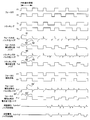
- FIG. 1 is a block diagram showing a configuration of an optical disc apparatus according to a first embodiment of the present invention. It is a wave form diagram which shows the waveform of the PWM drive signal of the actuator from which the start polarity which concerns on 1st Embodiment is changed. It is a wave form diagram which shows the noise of the PWM drive signal of the actuator which arises in the drive circuit which concerns on 1st Embodiment. It is a wave form diagram which shows the voltage and electric current of the both ends of an actuator which concern on 1st Embodiment. It is a top view which shows the state by which the wiring for PWM drive signals of the actuator which concerns on 1st Embodiment is arrange
- SYMBOLS 1 Optical disk, 2 ... Spindle motor, 3 ... Thread motor, 4 ... Objective lens, 5 ... Focus actuator, 6 ... Tracking actuator, 7 ... Flexible wiring part, 9 ... Light beam, 10 ... Optical pick-up, 11 ... Semiconductor laser, DESCRIPTION OF SYMBOLS 12 ... Laser driver, 13 ... Beam splitter, 14 ... Photo detector, 20 ... Main board
- a steep signal change of the PWM drive signal causes electromagnetic coupling between patterns.
- Noise component induced in the weak signal hereinafter referred to as “pulse noise”
- potential change in which the potential of the PWM drive signal propagates to the weak signal due to capacitive coupling between patterns or common impedance.
- the mechanical design is performed so that the actuator may be driven at a level that is approximately near the center, in other words, close to the state where the load is not driven, in the voltage range that can be varied by PWM drive. For this reason, in many cases, the modulation side edge of PWM is also not so far away.
- the potential change type noise is emphasized because the states of the drive outputs are aligned near the start point and end point of the PWM basic cycle. In particular, in the state where the load is not driven, all the drive outputs change the same voltage, so that the influence on the minute signal becomes more remarkable.
- the condition that these noises are strengthened among a plurality of PWM drive output pairs is relaxed, and the polarity is reversed so that the conditions cancel each other out.
- the phase of a pair of PWM basic cycles for driving one load is the same, so noise from two paired PWM drive signals emphasizes the influence on the weak signal. Since no emphasis occurs between the noises from other pairs of PWM drive signals or they cancel each other, it is possible to reduce the noise peak to the minute signal.
- the phases of the PWM basic cycle are the same and the polarities are reversed, the fixed-side edge of the PWM drive waveform simultaneously changes the voltage in the reverse direction. In general, the potential change type noise is also driven to cancel each other out. For this reason, the influence on a minute signal can be reduced.
- FIG. 1 shows the overall configuration of the optical disc apparatus according to the first embodiment.
- the optical disc apparatus includes an optical pickup 10 and a drive circuit 30.
- the optical pickup 10 includes a focus actuator 5 and a tracking actuator 6.
- the light beam 9 reaches the optical disk 1 through the objective lens 4 in the optical pickup 10. As a result, information is read from the optical disk 1 or written to the optical disk 1.
- the optical disc apparatus further includes a spindle motor 2 and a thread motor 3.
- the optical disk 1 is rotationally driven by the spindle motor 2.
- the optical pickup 10 is moved and driven in the radial direction of the optical disc 1 by the sled motor 3.
- the optical pickup 10 includes an objective lens 4, a semiconductor laser 11, a laser driver 12, a beam splitter 13, and a photodetector 14 in addition to the focus actuator 5 and the tracking actuator 6.
- the laser driver 12 generates a pulse waveform that drives the laser, and drives the semiconductor laser 11 that is the light source of the optical pickup 10.
- the light beam 9 generated from the semiconductor laser 11 irradiates the optical disc 1 via the beam splitter 13 and the objective lens 4. Then, the light beam 9 is reflected by the optical disc 1 to the photodetector 14. In this way, information is recorded on or reproduced from the optical disc 1 by light irradiation.
- the focus actuator 5 and the tracking actuator 6 are an example of the “actuator group” according to the present invention, and the objective lens 4 is moved to focus and track the light at a target position on the optical disc 1.
- the optical disc apparatus further includes, for example, a flexible wiring portion 7 having a wiring pattern on a flexible insulator.
- a flexible wiring portion 7 having a wiring pattern on a flexible insulator.
- the flexible wiring unit 7 transmits a reproduction signal reproduced from the optical disk 1 by the optical pickup 10 to the reproduction signal processing circuit 21, and transmits servo error signals such as a forus servo error signal and a tracking servo error signal to the servo signal extraction circuit 22.
- the recording signal recorded on the optical disc and the PWM drive signal generated by the drive circuit 30 are transmitted to the optical pickup 10.
- the focus actuator 5 and the tracking actuator 6 are, for example, voice coil type actuators using electromagnetic force.
- the focus actuator 5 moves the objective lens 4 along the direction of incidence of the light beam 9 on the optical disc 1 in order to focus the objective lens 4 in the optical pickup 10 with respect to the recording surface of the optical disc 1, and the tracking actuator 6 Then, the light spot of the objective lens 4 is displaced by a minute distance in the radial direction of the disk, and positioned on the track on the recording surface of the optical disk 1 with high accuracy.
- the focus actuator 5 and the tracking actuator 6 are driven using PWM-modulated drive voltage / current (that is, a plurality of PWM drive signals).
- the drive circuit 30 includes a spindle drive circuit 31, a thread drive circuit 32, a PWM reference oscillator 33, a focus drive circuit 35, and a tracking drive circuit 36.
- the drive circuit 30 is disposed on the main substrate 20 provided separately from the optical pickup 10 together with the reproduction signal processing circuit 21, the servo signal extraction circuit 22, the rotation control circuit 23, and the system controller 24.
- the spindle drive circuit 31, the rotation control circuit 23 and the system controller 24 in the main board 20, generate a spindle motor drive signal, and control the rotation speed and rotation position of the spindle motor 2.
- the thread drive circuit 32 When the shift amount of the objective lens 4 reaches a certain amount, the thread drive circuit 32 generates a thread motor drive signal and moves the optical pickup 10 to which the objective lens 4 is attached in the radial direction of the optical disc 1.
- the PWM reference oscillator 33 generates a PWM reference signal having a PWM reference period and outputs it to the focus drive circuit 35 and the tracking drive circuit 36.
- the focus drive circuit 35 generates a PWM drive signal for focus servo control based on the PWM reference signal and the focus error signal received from the servo signal extraction circuit 22. Based on the generated PWM drive signal, the focus actuator 5 is driven and controlled to move the objective lens 4 in a direction perpendicular to the optical disk.
- the tracking drive circuit 36 generates a PWM drive signal for focus servo control based on the PWM reference signal and the tracking error signal received from the servo signal extraction circuit 22. Based on the generated PWM drive signal, the tracking actuator 6 is driven and controlled to move the objective lens 4 in the radial direction of the optical disk.
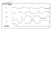
- FIG. 2 is a waveform diagram showing a waveform of the PWM drive signal of the actuator whose start polarity is changed according to the first embodiment
- FIG. 3 is a noise of the PWM drive signal of the actuator generated in the drive circuit according to the first embodiment.
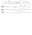
- FIG. 4 is a waveform diagram showing the voltage and current across the actuator according to the first embodiment.
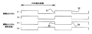
- PWM drive signals F1 and F2 of the drive output pair A of the focus actuator 5 and PWM drive signals F1 ′ and F2 ′ in which the polarity of the drive output A is inverted are shown.
- the average output is usually increased or decreased by modulating the pulse width within a fixed PWM basic period. That is, there are fixed-side voltage change edge portions 51 and 53 that are periodically generated every PWM basic period, and PWM modulation-side edge portions 52 and 54 that change the timing in accordance with the modulation degree of PWM.
- the polarity of the drive output pair A is reversed, the direction of the voltage transition is reversed on both the fixed side modulation side edge.
- the PWM drive signal is a binary signal, so that a steep voltage change occurs at the fixed side edge portion 51 (see FIG. 2) of the PWM drive signal of the focus actuator 5.
- a pulse noise 61 is generated in which a steep signal change is induced by coupling between patterns.
- pulse noise 62 is generated at the edge 52 (see FIG. 2) on the modulation side of the PWM drive signal.
- the voltage change of the PWM drive signal is generated as potential change noise 63 that propagates due to capacitive coupling between patterns or common impedance.
- similar pulse noise 64, 65 and potential change noise 66 are generated by the PWM drive signals T1, T2 of the tracking actuator 6.
- the fixed drive edge 53 and the PWM modulation edge 54 of the PWM drive signal with the positive / negative state inverted can be obtained. Since the voltage change is reversed with respect to the edge portion, 61 ′ and 62 ′ potential change noise 63 ′ with respect to the pulse noise 61 and 62 is generated. Since the noise due to the focus PWM drive signal whose polarity has been reversed has the opposite polarity to the noise due to the tracking PWM drive signal which has not undergone the polarity reversal, a canceling effect can be expected.
- the pulse noise generated at the fixed side edge portion of the PWM drive signal has a high canceling effect because the focus PWM drive signal and the tracking PWM drive signal are simultaneously and opposite in polarity.
- the pulse noise due to the PWM modulation side edge is generated at the same position with a duty of 50% in the non-driving state, they cancel each other.
- the edge generation timing is determined by the driving output voltage, so that it is unlikely that the edge is generated at the same time between focus and tracking. That is, although the canceling effect cannot be expected, the peak values can be kept low because they are not emphasized each other.
- the effect is demonstrated.
- the drive circuit can be easily configured because there is only one PWM pulse reference in the drive circuit as in the prior art.
- the PWM drive signals F1 and F2 that make a pair have the same basic period and phase of their outputs. Therefore, the voltage at both ends of the actuator coil is always the same potential when the actuator is not driven. That is, the current that flows through the coil of the actuator is not limited to the average current that flows through the fixed period, and the instantaneous current that is constantly flowing through the coil becomes zero.
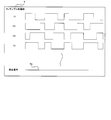
- FIG. 5 is a voltage waveform driven in a state where the wiring for the PWM drive signal of the actuator according to the first embodiment is arranged in the flexible wiring section 7, and
- FIG. 6 is the drive of FIG. It is the figure which showed the degree of the noise which influences with respect to the reproduction signal when playing.
- the PWM drive signal is concentrated on one end (illustrated) of the flexible substrate 7, and among them, the T1 of the PWM pulse pair of the tracking actuator 6 from the side where the PWM drive signal is not concentrated.
- the PWMs arranged close to each other The device has been devised so that the influence from the drive signal wiring cannot be canceled by the reverse polarity PWM drive signal arranged at a distance. Thereby, a larger cancellation effect can be exhibited, and the influence of noise on the reproduction signal is further reduced.
- the drive circuit generates a plurality of PWM drive signals so that the polarities at the start of the PWM cycle are different, thereby canceling the pulse noise and the potential change noise. As a result, it is possible to reduce a noise peak to a reproduction signal that is very small.
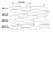
- FIG. 7 is a drawing having the same concept as FIG. 2, and shows the waveform of the PWM drive signal of the actuator whose start phase is changed according to the second embodiment of the present invention.
- the first embodiment is performed except that the phase of at least one other PWM drive signal is shifted with respect to the PWM cycle of one PWM drive signal, that is, each PWM cycle start point is shifted in time. It is the same as the form. Therefore, in the second embodiment, the description overlapping with that of the first embodiment is omitted, and common portions on the drawing are denoted by the same reference numerals, and only fundamentally different points are described with reference to FIG. explain.
- the phase of the pair of PWM drive signals for driving the tracking actuator 6 is advanced, when the phase is delayed, and when the phase is shifted by 180 degrees.
- the fixed edge side of the tracking PWM drive signal corresponding to the edge part 51 on the fixed side with respect to the PWM period of the focus PWM drive signal and the edge part 52 on the PWM modulation side.
- the edge part and the PWM modulation side edge part are moved to positions 55 and 56, respectively.
- the timing at which the edges of the two pairs of PWM drive signals are generated can be shifted, so that the two pairs of PWM drive signals have the same polarity change at the same time. By doing so, it is possible to avoid strengthening each other and affecting the minute signal.
- the phase is shifted by 180 degrees, the potential change on one pair of fixed sides and the potential change on the other pair of PWM modulation sides are almost canceled each other. Is obtained.
- FIG. 8 shows a drive circuit according to the third embodiment of the present invention.
- the drive circuit 30 includes a focus PWM comparator 301, a tracking PWM comparator 302, a focus output buffer 311, a tracking output buffer 312, a PWM reference oscillator 33, and an internal register 304.
- the input control voltage Vf is input from the outside via the input terminal Fin, and the input reference voltage Vref is input via the input pin REF.
- PWM pulses F1 and F2 are output according to the voltage difference between the two.
- PWM pulses T1 and T2 are output according to the voltage difference between the input control voltage Vt input via the input terminal Tin and the input reference voltage Vref input via the input terminal REF. Is done.
- the output PWM pulses F1 and F2 or T1 and T2 are applied between both terminals of the actuator coil, whereby the focus actuator 5 and the tracking actuator 6 are driven.
- the drive circuit 30 compares the PWM reference signal output from the PWM reference oscillator 33 according to the difference between the input control voltage Vf (or Vt) and the input reference voltage Vref.
- the PWM reference signal is, for example, a “sawtooth wave” having a PWM period as a period (that is, a signal in which a voltage change on the time axis forms a sawtooth wave), and the focus PWM comparator 301 causes the Fin voltage to be a sawtooth wave.
- the PWM signal Sf until the level is exceeded is output.
- the tracking PWM comparator 302 outputs a PWM signal St for driving the tracking actuator 6.
- the PWM signals Sf and St output from the PWM comparator are respectively input to the focus output buffer 311 and the tracking output buffer 312 to become differential output signals, and the PWM pulse output pair for driving the focus actuator 5 and the tracking actuator 6 is paired.
- F1, F2, and T1, T2 are transmitted to the actuator side via the flexible wiring portion 7.
- the internal register 304 exists to hold the start relationship of the PWM drive output set from the outside.
- the internal register 305 that can be accessed from an external controller such as the system controller 24 requires some kind of communication line with the external controller.
- three pins of serial data (DATA), serial clock (SCLK), and serial strobe (STB) of a three-wire serial communication system are prepared.
- the polarity of the PWM drive signal output pair F1, F2, and T1, T2 is set in the internal register 304 by an external input.
- the output from the PWM reference oscillator is selected by this set value, and thus the PWM cycle The starting polarity has been changed.
- the PWM reference oscillator outputs a sawtooth wave whose voltage gradually increases and a sawtooth wave whose voltage gradually decreases.
- the PWM reference oscillator The starting polarity is selected.
- the method of reversing the starting polarity of the PWM output signal is not limited to this method, and many variations are possible such as a single sawtooth wave that inverts the polarity of the comparator and the input signal.
- the drive circuit 30 also includes an enable pin (ENB) that controls whether or not the PWM output pin is actually driven. For example, when the logic level of the enable pin (ENB) is high, the output is driven, and when the logic level is low, the output is not performed. Thus, the PWM drive signal is not applied to the actuator when not required.
- ENB enable pin
- the polarity of the PWM pulse output pair F1, F2, and T1, T2 output from the drive circuit 30 can be set from the outside. As a result, it is possible to set the best state in which noise cancels out for a minute signal.
- FIG. 9 is a view having the same concept as in FIG. 8 and shows a drive circuit according to the fourth embodiment of the present invention.
- the fourth embodiment is the same as the third embodiment except that the output polarity can be selected without preparing a dedicated input pin or a communication pin with the controller. Accordingly, the description of the fourth embodiment that is the same as that of the third embodiment is omitted, and common portions in the drawing are denoted by the same reference numerals, and only the points that are basically different are described with reference to FIG. explain.
- the enable pin 303 ′ (ENB) in the drive circuit 30 performs not only high and low logic signals, but also three-value driving such that the high-impedance is not driven actively and results in an intermediate value level.
- the configuration is acceptable.
- One of the three states is defined as an output polarity definition state. For example, if the intermediate level is set to output prohibition and the low level is set to polarity, after setting the polarity with the ENB terminal set to low level, the output prohibition state that is the intermediate level and the output enable state that is the high level Switching can be performed without crossing the level indicating that the polarity is being set at the time of switching.
- the drive circuit 30 further includes a first polarity setting unit 315 and a second polarity setting unit 316.
- the comparator 305 that is an input to the first polarity setting unit 315 compares the input control voltage Vf and the input reference voltage Vref with each other when setting the polarity, and sets the polarity setting value to the first polarity setting unit 315 based on the magnitude relationship. To decide. This comparison value is evaluated only when the ENB terminal indicates that the polarity is being set, and is held in the first polarity setting unit when the state of the ENB terminal is not being set for polarity.
- the sawtooth wave used in the PWM comparator 301 is selected by the polarity setting held in the first polarity setting unit 315, and thereby the PWM cycle start polarity of the F1 and F2 outputs is determined.
- the second polarity setting unit 316 selects a sawtooth wave to be used by the PWM comparator 302, and thereby determines the PWM cycle start polarity of the T1 and T2 outputs.
- the PWM cycle start polarity can be set without increasing the input pin. Therefore, since there is no need for an input pin for adjusting the relationship of the drive output from the outside, the package of the drive circuit becomes smaller than when a dedicated pin is used, leading to a reduction in mounting area and cost reduction.
- An optical disc device and a drive circuit according to the present invention are provided in an optical disc device that irradiates a disc-shaped recording medium such as an optical disc with a laser beam and reads and / or writes a signal on the optical disc, the optical disc device, and the like. It can be used in the technical field of drive circuits.
Landscapes
- Optical Recording Or Reproduction (AREA)
- Optical Head (AREA)
Abstract
光ディスク装置は、少なくとも一つの光学素子(4)及び該光学素子を複数の移動方向に移動可能に支持するアクチュエータ群(5,6)を含み、光学素子を介して光ディスク(1)に対して信号を再生又は記録する光ピックアップ(10)と、PWM方式によって複数の移動方向に対応する複数の駆動信号をPWM周期毎に生成し、生成された複数の駆動信号によってアクチュエータ群を駆動するドライブ回路(30)とを備える。ドライブ回路は、一の駆動信号のPWM周期を基準としたとき、少なくとも一つの他の駆動信号のPWM周期が、相異なる開始関係となるように、複数の駆動信号を生成する。
Description
本発明は、例えば光ディスクなどの円盤状の記録媒体にレーザー光を照射し、光ディスクに対して信号の読取及び・又は書込みを行う光ディスク装置の技術分野に関する。
この種の光ディスク装置では、記録媒体上の目的位置に光を合焦させるため、対物レンズを移動させるアクチュエータが用いられる。アクチュエータの駆動には、連続的なアナログ電圧/電流が用いられる場合の他、PWM(Pulse Width Modulation:パルス幅変調)方式で変調された駆動電圧・電流が用いられる場合も多い。特にスリムタイプのドライバにおいては、ドライバ部での消費電力低減のためPWM駆動が多く用いられる。
通常、光ピックアップとドライブの信号処理基板との間は、FFC(フラットフレキシブルケーブル)等のフレキシブル配線部により、多数の配線が並行して配置された形で接続される。FFC内にはアクチュエータのPWM駆動信号の他、LD(Laser Diode:半導体レーザー)の光量制御信号や、光検出器からの再生信号等も同時に配置される。アクチュエータのPWM駆動信号は、これら並行して配線が配置される再生信号や光量制御信号等に比べ非常に大きく、数十倍以上になることも珍しくない。このように、相対的に微小である再生信号や各種制御信号とアクチュエータのPWM駆動信号とが近接・並行して配置されることにより、再生信号にアクチュエータ駆動信号によって誘起されたノイズがのってしまう。
このため、例えばアクチュエータを駆動する一対の駆動信号をフレキシブル配線部の両面に対向するように配置し、ノイズの誘起を抑制しようとしている光ディスク装置が提案されている(特許文献1参照)。
しかしながら、上記特許文献1に記載された技術によれば、駆動信号を位相が反転するPWM方式であるとしているが、位相が反転した正負一対のPWM信号で、一つのアクチュエータコイル両端を駆動するということは、アクチュエータに常に最大電流を流そうとしていることになる。この方式では、無駆動状態、即ちPWM周期で平均化してみればアクチュエータを駆動していない筈の状態に対しても、PWM周期内を更に細分化して考えると、アクチュエータの両端には常に逆極性の駆動信号が印加されており、その結果、常時最大の電流を流そうとしていることになる。従って、損失低減のために採用したPWM方式で常時損失を出していることとなり、消費電力低減に役立たないばかりか、発熱によりアクチュエータの破壊を招きかねないという技術的問題点がある。
また一般的に、通常のアクチュエータ駆動は、無駆動状態に対して、正負両極性の駆動が求められるが、一般的な光ディスク装置では、装置に供給される電源が正電源のみである事も多く、この場合は無駆動状態時にアクチュエータコイルの両端に同電位を加えておき、一方の端子が対となる端子に対してより低電位になるように駆動することでアクチュエータの負方向への駆動を実現する事が行われる。
このような駆動方式では、アクチュエータ駆動信号は同極性の信号となり、特許文献1のような打消し効果は期待できないばかりか、そのノイズは、再生信号や各種制御信号に対してむしろ強調されてしまう可能性さえある。
更に、ピックアップのアクチュエータは一方向のみに駆動されることは少なく複数の駆動方向(例えば、フォーカス、トラッキング、レンズチルト)に対応した複数の駆動信号を必要とする。即ちアクチュエータは「アクチュエータ群」として設けられる。この駆動には一つのドライブ回路ブロックで作られた、同一位相の基本周期をもつPWM波形が用いられるのが普通であるため、その数が多くなる程互いに強調しあって、より微小である再生信号などに影響を及ぼしやすくなっている。
本発明は、以上の問題点に鑑みてなされたものであり、PWM方式を採用しつつ再生信号を低ノイズで生成可能な、光ディスク装置及び該光ディスク装置に備えられるPWMドライブ回路を提供することを課題とする。
(光ディスク装置)
本発明に係る光ディスク装置は上記課題を解決するために、少なくとも一つの光学素子及び該光学素子を複数の移動方向に移動可能に支持するアクチュエータ群を含み、前記光学素子を介して光ディスクに対して信号を再生又は記録する光ピックアップと、PWM方式によって前記複数の移動方向に対応する複数の駆動信号をPWM周期毎に生成し、前記生成された複数の駆動信号によって前記アクチュエータ群を駆動するドライブ回路とを備えており、前記ドライブ回路は、前記複数の駆動信号のうち一の駆動信号の前記PWM周期を基準としたとき、前記複数の駆動信号のうち少なくとも一つの他の駆動信号の前記PWM周期が、相異なる開始関係となるように、前記複数の駆動信号を生成する。
本発明に係る光ディスク装置は上記課題を解決するために、少なくとも一つの光学素子及び該光学素子を複数の移動方向に移動可能に支持するアクチュエータ群を含み、前記光学素子を介して光ディスクに対して信号を再生又は記録する光ピックアップと、PWM方式によって前記複数の移動方向に対応する複数の駆動信号をPWM周期毎に生成し、前記生成された複数の駆動信号によって前記アクチュエータ群を駆動するドライブ回路とを備えており、前記ドライブ回路は、前記複数の駆動信号のうち一の駆動信号の前記PWM周期を基準としたとき、前記複数の駆動信号のうち少なくとも一つの他の駆動信号の前記PWM周期が、相異なる開始関係となるように、前記複数の駆動信号を生成する。
本発明の光ディスク装置では、例えば光ピックアップ内に配置された半導体レーザーを光源とし、光ピックアップ内の光学素子を介して光ディスク上に光ビームが照射される。照射された光は光ディスク上で反射され、光ピックアップ内の光学素子を介して光検出器へと導かれる。光検出器では光ディスクから反射されてきた光の強度分布の変化等により再生情報信号や追従制御のための制御信号が検出される。
光ピックアップは、光源からの光ビームを光ディスク上に合焦させ、且つまた、光検出器で光ディスクからの反射光が検出できるように光学素子を移動することができるアクチュエータを含む。ここに「光学素子」は、通常、アクチュエータによって移動させられる対物レンズの場合が多いが、BD(Blu‐ray Disk)対応ピックアップのコリメータレンズのように、対物レンズに加えて又は代えて他の光学素子も可動とする物でもよい。また光学素子の「移動」は、位置を変える動きのみならず、姿勢や向き或いは傾き等を変化させる動きをも意味する。
光学素子を移動させて位置制御を行うアクチュエータは、通常、光ディスクに垂直な方向に対物レンズを移動させ、光ディスク上に光ビームを合焦させるフォーカスアクチュエータと、光ディスクの半径方向に対物レンズを移動させ、光ビームを光ディスク上のトラックに追従させるトラッキングアクチュエータを備える。即ちアクチュエータは、「アクチュエータ群」として設けられる。
アクチュエータ群にはまた、ディスクの反りによる収差を補正するために、対物レンズを傾けることが出来るチルト機構を備えることができる。このチルト機構は単独で対物レンズを傾けるチルトアクチュエータである場合の他に、フォーカスアクチュエータを例えばチルト方向に分割した2つのボイスコイルモータで構成し、2つのボイスコイルモータによるフォーカス方向の移動量の差分によって、レンズチルトを実現するように構成することもできる。
これらのアクチュエータ群は、例えばシステムコントローラーの指示のもと、光検出器から抽出される各種サーボ信号に従って、ドライブ回路内で作られた駆動信号によって駆動される。この際に、ドライブ回路は、複数の移動方向に対応する複数の駆動信号をPWM周期毎に生成し、生成された複数の駆動信号によってアクチュエータを駆動する。例えば、フォーカスドライブ回路において、フォーカスエラー信号に基づいて、フォーカスサーボ制御用の駆動信号が生成される。更に、このフォーカスサーボ制御用の駆動信号に基づいて、フォーカスアクチュエータが駆動制御され、対物レンズが光ディスクに垂直な方向にシフトされる。他方、トラッキングドライブ回路において、トラッキングエラー信号に基づいて、トラッキングサーボ制御用の駆動信号が生成される。更に、このトラッキングサーボ制御用の駆動信号に基づいて、トラッキングアクチュエータが駆動制御され、対物レンズが光ディスクの径方向にシフトされる。
ここで「駆動信号」とは、パルス幅変調(PWM:Pulse Width Modulation)された駆動信号(即ち、PWM駆動信号)であり、「PWM」とはある基本単位時間内にどれだけの期間の幅を持つパルスを発生させるかを制御することにより、一定の波高値をもつパルスを用いて、あたかも波高の異なる電圧若しくは電流が加えられているかのように制御する手法である。この時の基本単位時間をPWM周期と呼び、一定の駆動信号を出力し続ける場合、駆動信号としてはPWM周期ごとに同じパルス波形を繰り返すこととなる。言い換えれば、PWM周期ごとにパルスのON/OFFを繰り返すのであるから、PWM周期の開始時点ではそれまでOFFであったパルスがONへと変化し、PWM周期内のいずれかのタイミングでON状態のパルスがOFFへと変化する事を意味している。
ボイスコイルモータ(VCM:Voice Coil Motor)のようなアクチュエータを考えるとき、ボイスコイルの両端に加える電圧関係を逆にすることでアクチュエータの移動方向を反転させることが出来る。この為にPWMパルスに負の波高値をもつパルスを用いることもできるが、通常はボイスコイル両端をいずれも例えばデューティ50%の変調幅をもつ駆動信号で駆動しておき、ボイスコイルを正方向に駆動するときは一端のデューティを例えば60%に増加し、逆に負方向に駆動するときは他の一端のデューティを例えば60%に増加させることで、ボイスコイル両端の電圧差を逆転させるような制御手法が行われる。
光ピックアップにはまた、対物レンズを移動させるアクチュエータの他に、ディスクの球面収差を補正することの出来るコリメータアクチュエータや、LDノイズを低減するためにLDから出射光までの透過率を変化させるような光学フィルタアクチュエータを備える場合がある。
光ディスクは、例えば光検出器により検出された各種信号に基づき光ディスクの回転数を制御する回転制御回路からの信号を受け、スピンドルドライブ回路で駆動されたスピンドルモータによりその回転数が制御される。
光ピックアップ全体は、光ディスクのトラックに追従するトラッキングアクチュエータが、おおむね中立位置に位置するようにスレッドモータにより半径方向に移動される。
光ピックアップが、光ディスクの半径方向に移動できるように、光ピックアップと装置本体に固定されたメイン基板との間はFFC、FPC(フレキシブルプリント基板)等のフレキシブルな部材で信号のやりとりが行われる。この時フレキシブル部材の中では駆動信号のようなエネルギーの大きい信号とディスクからの再生信号のような微弱信号とが並行して配線されることとなる。
ここで、微弱信号にはフォーカス及びトラッキングサーボをかけるためのエラー信号、ディスクに書き込まれた情報を再生したRF(Raido Frequency)信号、LDの光量をモニタする光量モニタ信号、光量モニタ信号をもとにLDへの駆動電流を制御する光量制御信号などがある。
本案のドライバ回路では更に、駆動信号のうち一対の駆動信号のPWM周期を基準としたとき、少なくとも一つの他の駆動信号のPWM周期が、相異なる開始関係となるように駆動信号を発生させることが出来る。ここに「開始関係」とは、例えばある一対のPWM周期の開始する時点における他のPWM周期の位相、極性などの波形の状態を意味する。即ち、ある一対のPWM周期の開始時点において、他の少なくとも1つの駆動信号は同時にPWM周期の開始時点をむかえない、またはこれに代えて若しくは加えて、PWM周期の開始時点でのPWMを構成するパルスの状態が逆になっている。
以上の構成により、通常は、複数の駆動信号がPWM周期の開始時に、同時に同じ極性の変化をすることで互いに強調しながら微小信号に影響を与えてしまうのに対し、本案では、駆動信号の変化するタイミングやノイズの極性を分散させることが出来るため、複数の駆動信号の重ね合わせによる強調効果を軽減することができ、よって微小信号に対するノイズの飛び付きを軽減することができる。
更に、アクチュエータ群を構成する一つのアクチュエータに関して見れば、無駆動状態でのその両端は同電位に駆動されるため、アクチュエータに無駄に電流を流すことがない。この結果、PWM駆動方式の利点である低損失はなんら失われておらず、アクチュエータが無用に発熱することもなくなるのである。
本発明の光ディスク装置の一態様では、前記ドライブ回路は、前記相異なる開始関係として、前記PWM周期の位相が相異なるように、前記複数の駆動信号を生成する。
この態様によれば、ドライブ回路は、複数の駆動信号のうち一対の駆動信号のPWM周期を基準としたとき、少なくとも一つの他の駆動信号のPWM駆動周期との間に位相差を持たせることができる。即ち、ある一対の駆動信号がそのPWM周期の開始時点にあるときに、他の少なくとも1つの駆動信号はPWM駆動周期の開始時点とならない駆動信号を出力することができる。
例えば、PWM周期が100mSecである場合に、フォーカス方向の駆動信号が新たなPWM周期を開始し、フォーカスアクチュエータに対するPWMパルスのレベル変化が生じた時点から50mSec後に、トラッキング方向の駆動信号に対する新たなPWM周期が開始され、トラッキングアクチュエータに対するPWMパルスのレベル変化が生じるような駆動をすることができる。なお、PWM周期同士のずれ量は時間であってもよいし、PWM周期を360度とする位相で定義されてもよい。
この構成によれば、PWM周期の開始時点で複数の駆動信号が同時にレベル変化を起こすことが避けられるため、微小信号に対してPWM周期開始時に発生するノイズのピーク値を低減することができる。
また、アクチュエータの両端に同一の駆動信号を与えておき、負方向の駆動を可能にする場合を考えると、例えば無駆動状態であっても、アクチュエータ自体に流れる電流はないものの、各端をある電位に変化させるための電流は必要であり、通常の構成においては、複数の駆動信号が同時同極性に変化するため、ドライブ回路の電源にはこの電流が一斉に流れることになるが、本方式では複数の駆動信号が同時に同極性に変化することが避けられる。このため、ドライブ回路の電源に流れる電流のピークも抑えることができる。特に、二対のPWM駆動周期が互いに180度ずれている場合、ある一対の出力をいままで駆動していた電流が必要なくなる瞬間に別の一対の出力を駆動するための電流が必要になるため、夫々の増減が打ち消しあい、電流変化の減少につながる。
本発明の光ディスク装置の他の態様では、前記ドライブ回路は、前記相異なる開始関係として、前記PWM周期の開始時における波形の極性が相異なるように、前記複数の駆動信号を生成する。
この態様によれば、ドライブ回路は、複数の駆動信号のうち一対の駆動信号に対して、少なくとも一つの他の駆動信号の駆動信号を、PWM周期の開始時点における波形の極性が相異なるように生成する。すなわち、例えば、ある一対の駆動信号が、そのPWM周期の開始時点において、パルスのハイレベル、言い換え得るならば電圧のより高い状態から始まり、PWM周期の終了時点でパルスのローレベル、言い換えるならば電圧のより低い状態で終わる場合に、他の一対の駆動信号はそのPWM周期の開始時点において、パルスのローレベルから始まり、PWM周期の終了時点でパルスのローレベルで終わるように駆動信号を発生させるのである。
この時、複数の駆動信号のPWM周期は位相が揃っていると打消し効果が期待できるのでより望ましい。即ち、複数のPWM周期の位相が揃っているため、PWM周期の開始時点では複数の駆動信号で同時にパルスのレベル変化が生じる。しかしながら、ある一対の駆動信号と他の一対の駆動信号では、パルスのレベル変化の極性が逆となるため、微弱信号に対する影響が打ち消しあう形となり、よって微弱信号に現れるノイズ成分を軽減することが可能となる。
さらに、PWM周期の基準が複数の駆動信号で同一であるので、ドライブ回路に入力されたアナログ信号をパルス幅変調するためのタイミング基準が一つで済むため、ドライブ回路の構成が容易になるという利点もある。
なお、アクチュエータの駆動信号は、サーボのかかった定常状態ではおおむね駆動信号の可変範囲に対してほぼセンターで駆動されるように設計されることが普通である。よって、例えばフォーカスPWM駆動信号とトラッキングPWM駆動信号とのような相関の薄い駆動信号同士であっても、サーボのかかった定常状態で駆動信号のデューティがほぼ50%になることが期待され、このような駆動信号の極性が反転していればPWM周期のエッジ部分のみならず、PWM周期全体に対して打消し効果を期待することができる。
本発明の光ディスク装置の他の態様では、前記アクチュエータ群は、前記複数の移動方向に対応する複数の動力源を有し、該複数の動力源は、前記複数の駆動信号によって同時に駆動され、前記複数の移動方向のうち一の移動方向への移動が、前記複数の動力源のうち少なくとも二つの動力源を同時に駆動することによって達成される場合、前記少なくとも二つの動力源は、前記PWM周期の位相が互いに等しくなるように駆動される。
例えば対物レンズを光ディスクの半径方向にチルトさせることを考える場合、チルトのみを制御する専用のアクチュエータを用意する以外に、フォーカスアクチュエータを対物レンズに対して、光ディスクのより外周側とより内周側の2カ所に設け、2つのアクチュエータの変位量の差分がチルト量となるように、フォーカス兼チルト用アクチュエータを構成することができる。このような構成ではフォーカス方向という一つの移動方向をもつ2つのアクチュエータが存在するが、これら2つのアクチュエータに対してそれぞれのPWM周期の位相をずらす場合、2つのアクチュエータの駆動力が同じになるような駆動信号を出力するとしても、実際にアクチュエータに駆動力が発生するタイミングがPWM周期の位相ずれ分だけ異なる。このため、瞬間的にはフォーカス方向以外の駆動力、この場合にはチルト方向の駆動力が発生することになるため好ましくない。
従って、一つの移動方向を担う、複数のアクチュエータは互いに同じPWM周期で駆動するように構成し、ノイズ軽減のためにPWM周期の位相をずらすのは例えばトラッキングアクチュエータを駆動する信号に選ぶことが望ましい。
この様態によれば、駆動信号によるノイズを低減する施策を採りながらも、本来意図しない駆動力が発生することを避けることができる。
本発明の光ディスク装置の他の態様では、前記光ピックアップと前記ドライブ回路が取り付けられているメイン基板との間に、前記複数の駆動信号と前記再生又は記録される信号が並行するフレキシブル配線部を更に備えており、前記複数の駆動信号用の複数の配線は、前記フレキシブル配線部で相隣接するように配置されている。
この態様によれば、駆動信号は本体側に置かれたドライブ回路から、光ピックアップの移動に伴って屈曲状態の変化するフレキシブル配線部分(より具体的には、可撓性のある絶縁物上に配置されている配線)を通って、光ピックアップへと導かれる。このフレキシブル配線部では、アクチュエータの駆動信号用の配線の他に、LDを灯すための各種信号用の配線や、光検出器で検出された再生信号等の配線なども同時に配置される。
通常、このフレキシブル配線部は光ピックアップが光ディスクの半径方向に移動する場合に負荷とならないように十分な長さを確保して設計されるが、この結果、駆動信号と微弱信号がフレキシブル配線部の長さに渡って並走することとなり、ノイズが飛び付きやすい。通常フレキシブル配線部は、FFCなどのような帯状の部材で構成されるため、配線は帯状の面内に並行して配置されることとなる。このため、ある微弱信号に対してノイズ源となる駆動信号までの距離はフレキシブル配線部の信号配置に従って決定され、より近い駆動信号からより強くノイズを受けることになる。
本発明の構成では、条件により駆動信号によるノイズの打消し効果を期待できる場合があるが、ノイズを受ける微弱信号と、互いにノイズを打ち消しあう関係にある駆動信号との距離が大きく異なると、誘起されるノイズの量が異なってしまう。このため、十分な打消し効果が期待できなくなる。従って、ノイズを打ち消しあう関係の駆動信号同士を隣接して配置することにより、他の微弱信号までの距離をおおむね同一とし、もってノイズの打消し効果を十分発揮することができるようになる。
なお、微弱信号と打消し効果を期待する2つの駆動信号との距離をより厳密にする手法としては、特許文献1の示すような両面FPC(フレキシブルプリントケーブル)が考えられるが、通常、両面FPCは片面FPCやFFCに対してコストアップとなるのみならず、両面FPCは屈曲性において片面で構成されたFPCやFFCに劣り、特に両面の配線を重ねて配置した場合には、屈曲時の曲率の違いから断線を招きやすいことが知られている。
本発明によれば、屈曲性に優れる単一面での配置であっても、PWM駆動による微弱信号へのノイズの誘起を低減することが可能である。よって光ピックアップ移動に対する抵抗を軽減し、繰り返し屈曲運動に対する断線の危険を避けることができる。
なお、ドライブ回路の存在する位置はメイン基板に限らず、多くのスリムタイプドライブがそうであるように、スピンドルモータに付随する基板等にあってもよい。
この態様では、前記アクチュエータ群は、前記複数の移動方向に対応する複数の動力源を有し、該複数の動力源は夫々、前記駆動信号を構成する一対のPWMパルスにより駆動され、前記一対のPWMパルスに対する一対の配線の間には、少なくとも一本の前記開始関係の異なる駆動信号に対する配線が配置されてもよい。
例えば、フレキシブル配線部の配線を横切る方向の一端に駆動信号群(即ち、PWM駆動信号群)を配置し、他の一端に微弱信号群を配置することを考える。このように配置することでPWM信号群と微弱信号群の間の距離を増加させることができ、よって駆動信号群によるノイズの飛び付き量を抑制することができるが、この時、ある微小信号への駆動信号群の影響量は距離が近い程大きいことになる。
本発明では、駆動信号は互いに同じ開始条件の一対のPWMパルスから構成されており、互いに異なる開始条件をもつのは、他の一対のPWMパルスである。例えば、フォーカスアクチュエータを駆動する一対2本のPWMパルスとトラッキングアクチュエータを駆動する一対2本のPWMパルスとが打消しの関係にあるとする。
ここで、通常行われるように対となる駆動信号の配線を隣接させて順に配置した場合、例えばフォーカスPWMパルス2本を配置した隣にトラッキングPWMパルス2本を配置した場合、対となるPWMパルスの微弱信号からの平均距離が異なるため、十分な打消し効果が得られない。これに対し、微弱信号に近い側から、フォーカスPWMパルスの1本、トラッキングPWMパルス一対2本、フォーカスPWMパルスの残り1本の順に配置すれば、対となるPWMパルスの微弱信号からの平均距離が等しくなる。このため、大きな打消し効果を発揮することができ、ノイズに対してより一層の軽減を実現可能となる。
(ドライブ回路)
本発明に係るドライブ回路は上記課題を解決するために、被移動物を複数の移動方向に移動可能とするためのアクチュエータ群を駆動するためのドライブ回路であって、PWM方式によって前記複数の移動方向に対応する複数の駆動信号をPWM周期毎に生成し、前記生成された複数の駆動信号によって前記アクチュエータ群を駆動する駆動信号生成手段を備え、前記駆動信号生成手段は、前記生成された複数の駆動信号のうち一の駆動信号の前記PWM周期を基準としたとき、前記生成された複数の駆動信号のうち少なくとも一つの他の駆動信号の前記PWM周期が、相異なる開始関係となるように、前記複数の駆動信号を生成する。
本発明に係るドライブ回路は上記課題を解決するために、被移動物を複数の移動方向に移動可能とするためのアクチュエータ群を駆動するためのドライブ回路であって、PWM方式によって前記複数の移動方向に対応する複数の駆動信号をPWM周期毎に生成し、前記生成された複数の駆動信号によって前記アクチュエータ群を駆動する駆動信号生成手段を備え、前記駆動信号生成手段は、前記生成された複数の駆動信号のうち一の駆動信号の前記PWM周期を基準としたとき、前記生成された複数の駆動信号のうち少なくとも一つの他の駆動信号の前記PWM周期が、相異なる開始関係となるように、前記複数の駆動信号を生成する。
本発明に係るドライブ回路によれば、上述した本発明に係る光ディスク装置の場合と同様の原理によって、駆動信号の変化するタイミングやノイズの極性を分散させることが出来るため、複数の駆動信号の重ね合わせによる強調効果を軽減することができる。よって微小信号に対するノイズの飛び付きを軽減することができるのみならず、例えば同一のPWM駆動周期をもちPWM駆動周期の開始極性のみが異なる場合などでは、複数の駆動信号により誘起されるノイズ同士が互いに打ち消しあうことにより、一層のノイズ低減効果を発揮することができる。
更に、一対の駆動信号としては、無駆動状態で負荷に流れる電流を常時なくすことができるため、PWM駆動方式による消費電力低減効果を維持することができる。
本発明に係るドライブ回路は、光ディスクに対して信号の読取及び・又は書込みを行う光ディスク装置に備えられてもよいし、HDD(ハードディスクドライブ)のような、信号検出部をその近傍に置いたアクチュエータで駆動するような装置に備えられてもよい。
本発明のドライブ回路の一態様では、前記駆動信号生成手段は、前記複数の駆動信号を発生する発生手段と、前記PWM周期が前記相異なる開始関係となるように、前記発生された又は発生される複数の駆動信号を調整する調整手段とを含み、前記調整手段は、当該ドライブ回路の外部から入力された調整信号によって、前記発生された又は発生される複数の駆動信号の前記開始関係が相異なるように、前記複数の駆動信号を調整する。
この態様によれば、ドライブ回路における調整手段は、ドライブ回路の外部、例えばシステムコントローラーから入力された調整信号によって、駆動信号の開始時点の位相ずれ又は極性反転などを選択する事ができる。
この調整手段は、例えばドライブ回路をコントロールするシステムコントローラーからレジスタなどを書き換えることで極性設定を行う手法で実現される。即ち、外部のシステムコントローラー等のコントローラーからアクセスできる内部レジスタが用意され、外部コントローラーとの間に何らかの通信線が必要である例えば通常の3線式シリアル通信部として、シリアルデータ、シリアルクロック、シリアルストローブの3ピンが追加されてもよい。
なお、別の方法として、専用の入力ピンにどのようなレベルの値が加えられているかで設定してもよい。例えば、極性切替のために外部入力ピンとして、フォーカスドライブ回路及びトラッキングドライブ回路のそれぞれに対して一つの入力ピンが追加されてもよい。
信号間の結合に起因するノイズの飛び付きは、その影響が設計初期には予測し難い一方、その解消には信号の配置順序を変更するなどの物理的変更が必要となる。本態様によれば、いったん回路基板等を作り上げた後であっても駆動信号が及ばす影響を確認しながら最良となる駆動信号の開始関係を設定することができる。
また、ノイズを受ける微小信号は複数存在する場合が普通であり、その影響度は微小信号と駆動信号との距離、微小信号の回路インピーダンス、微小信号の信号レベル、その微小信号の重要度により様々な状態を示すが、本態様によれば各時点で最良の駆動方式を選択することもできる。例えば、BDディスクを再生するときには必要だが、DVDディスクを再生するときには必要ない微小信号があったとする。この微小信号に駆動信号からのノイズが飛び付く場合に、BD再生時には駆動信号の開始関係を調整しこの微小信号に対する影響を軽減するが、DVD再生時であればこの微小信号にノイズが載ったとしても問題とはならない。このため、別なより重要な微小信号へのノイズが軽減されるような設定を選ぶことができる。
本発明のドライブ回路の他の態様では、前記調整手段は、前記複数の駆動信号の入力に対して、予め設定された調整パターンで、前記発生された複数の駆動信号の開始関係が相異なるように、前記複数の駆動信号を調整する。
通常、一対の駆動信号を発生する一のPWM駆動回路には、その駆動量を決定する一のPWM駆入力信号が存在し、このPWM駆動入力信号のレベルが基準電圧に対してどの程度大きい若しくは小さいかで駆動信号の変調度合いを決定している。ドライブ回路にはまた、PWM駆動出力の出力自体を許可・禁止するENB(イネーブル)ピンが存在する。従来、このイネーブルピンはロジック入力であり、出力の許可と禁止の2状態を判別できれば機能として十分である。このイネーブルピンに対し、例えば、ハイ・ロー2値の他にその中間値を用いて一本の信号線で3値の伝送を行うこととすれば、従来の出力禁止、出力許可に加え、極性設定中という状態を表現できることになる。そして、ENBピンを極性設定中のレベルとし、このときにPWM駆動回路の入力ピンのレベルが基準電圧ピンより高ければ極性反転、低ければ極性反転は行わないなどと定義することで、PWM駆動回路の入力ピンを用いてPWM駆動出力の開始関係を指定できる。この定義は、その後ENBピンのレベルを極性設定中以外の状態へと変化させることで内部に保持されるようにしておく。その後、アナログ入力ピンへの電圧は通常のサーボループによるものに切り替えられ、ENBピンをドライバ出力可能へと変化させることでサーボ系でのドライブが可能となる。
なお、極性設定中を示すENBの信号レベルは3値のいずれとすることも可能である。例えば、ハイ若しくはローレベルを極性設定中とすれば、極性設定後に出力禁止と出力可能を切り替えた場合でも、その切替時に極性設定中を示すレベルを跨ぐことなく状態の切替を行うことができる。この場合、ENBピンの中間値レベルが指示する状態が出力許可であると、極性設定中から中間レベルに移行した瞬間に、PWM駆動周期の開始条件を設定した電圧レベルで出力を駆動してしまうため、中間レベルの指示する状態は出力禁止であることが望ましい。
一方、中間値レベルを極性設定中とし、極性切替を追加してもよい。この場合、出力の許可と禁止を指示するレベルが、一般的なドライブ回路と同等になるため、従来との互換性を確保することができる。なお、この態様を用いる場合には、ENBピンは出力許可と出力禁止の切り替え時点で極性設定中の信号レベルを通過するため、信号レベルがある期間以上連続して極性設定中を指示する場合のみ極性設定状態に移行するような回路構成とする必要がある。
各PWM駆動出力には対応するPWM駆動入力が存在するため、各PWM駆動出力の開始条件を個別に設定するためそれぞれに極性指定の入力ピンを追加する必要が無く、極めて都合がよい。
よって、専用ピンを用いる場合に比べてドライブ回路のパッケージが小さくなり、必要とする実装面積を減少させると共にコストダウンにつながる。
尚、本発明のドライブ回路においても、上述した本発明の光ディスク装置の場合と同様の各種態様を採ることが可能である。
本発明の作用及び他の利得は次に説明する実施するための発明を実施するための最良の形態から明らかにされる。
以上詳細に説明したように、本発明の光ディスク装置は、複数の駆動信号のうち一の駆動信号のPWM周期を基準としたとき、複数の駆動信号のうち少なくとも一つの他の駆動信号のPWM周期が、相異なる開始関係となるように、複数の駆動信号を生成するドライブ回路を備え、他方、本発明のドライブ回路は、調整手段等によってこのように複数の駆動信号を生成する駆動信号生成手段を備えるので、微小である再生信号などへのノイズを低減することができる。更に、アクチュエータに常に最大電流を流すことを妨げられることになるので、消費電力低減に役立ち、発熱によりアクチュエータの破壊を有効的に防止することが可能となる。
1…光ディスク、2…スピンドルモータ、3…スレッドモータ、4…対物レンズ、5…フォーカスアクチュエータ、6…トラッキングアクチュエータ、7…フレキシブル配線部、9…光ビーム、10…光ピックアップ、11…半導体レーザー、12…レーザードライバ、13…ビームスプリッタ、14…光検出器、20…メイン基板、21…再生信号処理回路、22…サーボ信号抽出回路、23…回転制御回路、24…システムコントローラー、30…ドライブ回路、31…スピンドルドライブ回路、32…スレッドドライブ回路、33…PWM基準発振器、35…フォーカスドライブ回路、36…トラッキングドライブ回路
<本発明の原理>
先ず、具体的な実施形態について説明する前に、本発明の原理について説明する。
先ず、具体的な実施形態について説明する前に、本発明の原理について説明する。
本発明に係る「駆動信号」の一例である、PWM駆動信号のような急峻なエッジを持つ信号の微弱信号への飛びつきを考える場合、PWM駆動信号の急峻な信号変化がパターン間の電磁結合を介して微弱信号に誘起されるノイズ成分(以下「パルス性ノイズ」と称する)と、PWM駆動信号の電位そのものが、パターン間の容量結合や共通インピーダンスにより微弱信号に伝播するノイズ成分(以下電位変化型ノイズ)とを考える必要がある。
従来方式のように複数の同期したPWM駆動が行われる場合を考えると、パルス性ノイズはPWMパルスのエッジ部分に同期して発生するため、PWM駆動波形の固定側のエッジはPWM基本周期で互いに強調しあうノイズとして発生する。なお、PWMの変調側のエッジはPWMとして出力したい電圧に応じて異なったタイミングに存在するため、強調しあうことは少ない。但し、負荷を駆動していない状態ではPWMの変調側エッジも同じタイミングに揃うため互いに強調しあうこととなる。また、通常、定常サーボ状態ではPWM駆動で可変可能な電圧範囲のうち、概ねセンター付近、言い換えれば負荷を駆動していない状態に近しいレベルでアクチュエータを駆動すればよいように機械設計がなされる。このため、多くの場合にはPWMの変調側エッジもさほど離れていないところに存在することとなる。
電位変化型ノイズは、殆どの場合PWM基本周期の開始点及び終了点付近で、各駆動出力の状態がそろってしまうため、常に強調しあっていると言える。特に、負荷を駆動していない状態では、全ての駆動出力が同じ電圧変化をするため、微小信号への影響がより顕著になる。
本発明では、複数のPWM駆動出力対同士の間で、これらノイズが強めあう条件を緩和し、また、その極性を互いに逆にすることで打ち消しあう条件に変えることで、PWM駆動信号から微小信号へのノイズの影響の軽減を図る。即ち、PWM駆動パルスのうち、一つの負荷を駆動する一対のPWM基本周期の位相は同じ為、一対をなす2本のPWM駆動信号からのノイズは微弱信号への影響を強調することになるが、他の対となるPWM駆動信号からのノイズとの間では強調が起きない若しくは互いに打ち消す関係にあるため、微小信号へのノイズのピークを低減することが出来るのである。特に、PWM基本周期の位相が同じで極性が互いに反転している場合には、PWM駆動波形の固定側のエッジは同時に逆方向の電圧変化をするため、パルス性ノイズの打ち消し効果が発生すると同時に、電位変化型ノイズに関しても概ね打ち消しあう駆動がなされる。このため微小信号への影響を軽減することができる。
以下、本発明の光ディスク装置及びドライブ回路に係る各実施形態を図面に基づいて説明する。
<第1実施形態>
本発明の第1実施形態について、図1乃至図7を参照して説明する。
本発明の第1実施形態について、図1乃至図7を参照して説明する。
先ず、第1実施形態に係る光ディスク装置の全体構成について図1を参照して説明する。ここに図1は、第1実施形態に係る光ディスク装置の全体の構成を示す。
図1において、光ディスク装置は、光ピックアップ10及びドライブ回路30を備えて構成されている。光ピックアップ10は、フォーカスアクチュエータ5及びトラッキングアクチュエータ6を備える。
光ディスク装置では、光ピックアップ10において、光ビーム9が対物レンズ4を介して光ディスク1に至る。これによって、光ディスク1から情報の読み取り、又は光ディスク1に情報の書込みを行う。
光ディスク装置は、更にスピンドルモータ2及びスレッドモータ3を備えている。スピンドルモータ2によって、光ディスク1が回転駆動される。他方、アクセス動作などのトラック間を大きく移動する際、スレッドモータ3によって、光ピックアップ10が光ディスク1の半径方向に移動され駆動される。
光ピックアップ10は、フォーカスアクチュエータ5及びトラッキングアクチュエータ6に加えて、対物レンズ4、半導体レーザー11、レーザードライバ12、ビームスプリッタ13及び光検出器14を備えて構成されている。レーザードライバ12は、レーザーを駆動するパルス波形を生成し、光ピックアップ10の光源である半導体レーザー11を駆動する。半導体レーザー11から発生された光ビーム9は、ビームスプリッタ13及び対物レンズ4を介して、光ディスク1に照射する。そして、光ビーム9が光ディスク1によって光検出器14に反射される。このように光照射により光ディスク1に対する情報の記録又は再生が行われる。
フォーカスアクチュエータ5及びトラッキングアクチュエータ6は、本発明に係る「アクチュエータ群」の一例であり、光ディスク1上の目的位置に光を合焦させまたトラッキングするため、対物レンズ4を移動させる。
光ディスク装置は、更に例えば可撓性を有する絶縁物上に配線パターンを有したフレキシブル配線部7を備えて構成されている。フレキシブル配線部7を通じて、ドライブ回路30などが置かれたメイン基板20と、光ピックアップ10とが接続される。光ピックアップの移動に伴ってフレキシブル配線部7の屈曲状態が変化することで接続が維持される。フレキシブル配線部7によって、光ピックアップ10で、光ディスク1から再生された再生信号が再生信号処理回路21へ伝送され、フォーラスサーボエラー信号及びトラッキングサーボエラー信号などサーボエラー信号がサーボ信号抽出回路22へ伝送されると共に、光ディスクに記録される記録信号及びドライブ回路30で生成されたPWM駆動信号が光ピックアップ10へ伝送される。
フォーカスアクチュエータ5及びトラッキングアクチュエータ6は、例えば電磁力を利用したボイスコイル形のアクチュエータである。フォーカスアクチュエータ5は、光ピックアップ10における対物レンズ4を光ディスク1の記録面に対して焦点を合わせるため、対物レンズ4を光ビーム9の光ディスク1に入射する方向に沿って移動させ、トラッキングアクチュエータ6は、対物レンズ4の光スポットをディスク半径方向に微小距離変位させて光ディスク1の記録面上のトラックに高精度に位置決めする。ここのフォーカスアクチュエータ5及びトラッキングアクチュエータ6の駆動には、PWM変調された駆動電圧/電流(即ち、複数のPWM駆動信号)が用いられる。
ドライブ回路30は、スピンドルドライブ回路31、スレッドドライブ回路32、PWM基準発振器33、フォーカスドライブ回路35、及びトラッキングドライブ回路36を備えて構成されている。ドライブ回路30は、再生信号処理回路21、サーボ信号抽出回路22、回転制御回路23、及びシステムコントローラー24と共に、光ピックアップ10とは別に設けられたメイン基板20に配置されている。
スピンドルドライブ回路31、並びにメイン基板20における回転制御回路23及びシステムコントローラー24は、スピンドルモータ駆動信号を生成し、スピンドルモータ2の回転速度及び回転位置を制御する。スレッドドライブ回路32は、対物レンズ4のシフト量が一定量に達すると、スレッドモータ用駆動信号を発生し、対物レンズ4が取り付けられる光ピックアップ10を光ディスク1の径方向に移動させる。PWM基準発振器33は、PWM基準周期を有するPWM基準信号を生成して、フォーカスドライブ回路35及びトラッキングドライブ回路36へ出力する。
フォーカスドライブ回路35では、PWM基準信号及びサーボ信号抽出回路22から受信されたフォーカスエラー信号に基づいて、フォーカスサーボ制御用のPWM駆動信号が生成される。この生成されたPWM駆動信号に基づいて、フォーカスアクチュエータ5は駆動制御され、対物レンズ4を光ディスクに垂直な方向に移動させる。
同様に、トラッキングドライブ回路36では、PWM基準信号及びサーボ信号抽出回路22から受信されたトラッキングエラー信号に基づいて、フォーカスサーボ制御用のPWM駆動信号が生成される。この生成されたPWM駆動信号に基づいて、トラッキングアクチュエータ6は駆動制御され、対物レンズ4を光ディスクの径方向に移動させる。
次に、第1実施形態に係るPWM駆動信号の開始関係の基本動作及びその効果について図2乃至図4を参照して説明する。ここに図2は第1実施形態に係る開始極性が変えられるアクチュエータのPWM駆動信号の波形を示す波形図であり、図3は第1実施形態に係るドライブ回路に生じるアクチュエータのPWM駆動信号のノイズを示す波形図であり、図4は第1実施形態に係るアクチュエータ両端の電圧及び電流を示す波形図である。
図2において、フォーカスアクチュエータ5の駆動出力対AのPWM駆動信号F1及びF2、駆動出力Aが極性反転されたPWM駆動信号F1'及びF2'が示されている。PWMでは通常、一定のPWM基本周期の中のパルス幅を変調することで、その平均出力を増減する。即ち、PWM基本周期毎に定期的に発生する固定側の電圧変化エッジ部51及び53と、PWMの変調度に応じてそのタイミングを変化させるPWM変調側エッジ部52及び54が存在する。ここで、駆動出力対Aの極性を反転すると、固定側エッジ変調側エッジともに電圧変移の向きも逆となる。
図3に示すように、PWM駆動方式では、PWM駆動信号が二値信号であるため、フォーカスアクチュエータ5のPWM駆動信号の固定側エッジ部51(図2参照)において、急峻な電圧変化を生じ、急峻な信号変化がパターン間の結合により誘起されるパルス性ノイズ61が発生される。これと共に、PWM駆動信号の変調側のエッジ部52(図2参照)などにおいて、パルス性ノイズ62が発生される。同時にPWM駆動信号の電圧変化が、パターン間の容量結合や共通インピーダンスにより伝播する電位変化型ノイズ63として発生することとなる。同様に、トラッキングアクチュエータ6のPWM駆動信号T1、T2によって、同様のパルス性ノイズ64,65及び電位変化型ノイズ66が発生する。
ここで、フォーカス駆動出力対F1、F2の極性を反転すると、正負状態が反転されたPWM駆動信号の固定側エッジ部53及びPWM変調側のエッジ部54を得ることができる。このエッジ部に対しては電圧変化が逆となっているため、パルス性ノイズ61,62に対する61‘、62’電位変化型ノイズ63‘が生じることとなる。これら極性反転されたフォーカスPWM駆動信号によるノイズは、極性反転を受けていないトラッキングPWM駆動信号によるノイズと逆極性になるので、打ち消し効果を期待することができる。特にPWM駆動信号の固定側エッジ部に生じるパルス性ノイズはフォーカスPWM駆動信号とトラッキングPWM駆動信号とで同時かつ逆極性となるため打ち消し効果が高い。また、PWM変調側のエッジによるパルス性ノイズは、無駆動状態ではデューティ50%で同位置に発生するため互いに打ち消しあう。無駆動状態以外ではそのエッジの発生タイミングは駆動出力電圧によって決まるため、フォーカスとトラッキングとの間で同時に発生することは少ないと考えられる。即ち、打ち消し効果は期待できないものの、互いに強調することもないため、そのピーク値を低く保つことができる。
電位変化型ノイズは、反転されたフォーカスPWM駆動信号によるものがPWM周期の前半にマイナス方向に作用する一方、トラッキングPWM駆動信号によるものがPWM周期の前半にプラス方向に作用するため、ある程度の打ち消し効果が発揮される。本実施形態では、ドライブ回路内部にPWMパルスの基準は従来通り一つがあればよいため、ドライブ回路を構成することが容易となる。
ここで、図4に示すように、対をなすPWM駆動信号F1、F2は、それぞれの出力の基本周期・位相が同一に設定されている。よって、無駆動時にはアクチュエータコイル両端の電圧は常に同電位となり、即ちアクチュエータのコイルに流す電流としては、一定の期間で流す平均電流に限らず、コイルに常に流している瞬時電流もゼロになる。
次に、第1実施形態に係るアクチュエータのPWM駆動信号用の配線がフレキシブル配線部7で配置される状態について図5及び図6を参照して説明する。ここに図5は第1実施形態に係るアクチュエータのPWM駆動信号用の配線がフレキシブル配線部7で配置される状態で駆動されている電圧波形であり、図6は第5図の駆動が行われている時、再生信号に対して影響するノイズの度合いを示した図である。
図5に示すように、フレキシブル配線部7では、極性が反転されたフォーカスアクチュエータ5のPWM駆動信号F1'及びF2'用の配線、並びにトラッキングアクチュエータ6のPWM駆動信号T1及びT2用の配線が配置されている。アクチュエータの配線と並行して、光ピックアップ10から帰ってきた再生信号等の配線70もフレキシブル配線部7で配線され、この再生信号をこの説明での微弱信号とする。アクチュエータ駆動用の配線と微弱信号の配線とは、フレキシブル配線部7の同一面内に並行して配置される。このため、一本一本のPWM駆動信号配線からの距離が異なり、配線間の間隔が近いほど強く影響を受けることとなる(図6参照)。
従って、フレキシブル基板7の一方の端(図示上)にPWM駆動信号を集中して配置し、その中でも、PWM駆動信号の集中していない側より、トラッキングアクチュエータ6のPWMパルス対の一つのT1の配線、逆極性であるフォーカスアクチュエータ5のPWMパルス対F1'及びF2'の一対の配線、先のトラッキングアクチュエータ6のPWMパルス対の残りT2の配線という順に配置することで、近くに配置されたPWM駆動信号配線からの影響を、遠くに配置された逆極性のPWM駆動信号で打ち消しきれなくならないように工夫がなされている。これにより、より大きな打消し効果を発揮することができ、再生信号に対するノイズの影響がより一層軽減される。
なお、フレキシブル配線部7が片面で構成できることによって、より容易にしてフレキシブル配線部7の低コスト化を図れると共に、フレキシブル配線部7の屈曲性も十分に確保することが可能となる。
以上の構成によって、ドライブ回路がPWM周期の開始時点における極性が相異なるように複数のPWM駆動信号を生成することで、パルス性ノイズ及び電位変化性ノイズが打ち消しあう。このことによって、微小である再生信号などへのノイズのピークを低減することが出来る。
<第2実施形態>
本発明の光ディスク装置に係る第2実施形態について、図7を参照して説明する。ここに、図7は、図2と同趣旨の図面であり、本発明の第2実施形態に係る開始位相が変えられるアクチュエータのPWM駆動信号の波形を示す。
本発明の光ディスク装置に係る第2実施形態について、図7を参照して説明する。ここに、図7は、図2と同趣旨の図面であり、本発明の第2実施形態に係る開始位相が変えられるアクチュエータのPWM駆動信号の波形を示す。
第2実施形態では、一のPWM駆動信号のPWM周期に対して、他の少なくとも一つのPWM駆動信号の位相をずらす、即ちそれぞれのPWM周期開始点を時間的にずらすこと以外は、第1実施形態と同様である。よって、第2実施形態について、第1実施形態と重複する説明を省略すると共に、図面上における共通箇所には同一符号を付して示し、基本的に異なる点についてのみ、図7を参照して説明する。
図7に示すように、例えばフォーカスアクチュエータ5を駆動する一対のPWM駆動信号F1、F2と、他のPWM駆動信号例えばトラッキングアクチュエータ6を駆動する一対のPWM駆動信号T1、T2との間の位相関係を、トラッキングアクチュエータ6を駆動する一対のPWM駆動信号の位相が進んでいる場合、遅れている場合、180度ずれている場合について示している。この波形図に示すように、位相がずれることによって、フォーカスPWM駆動信号のPWM周期に対して固定された側のエッジ部51及びPWM変調側のエッジ部52と対応するトラッキングPWM駆動信号の固定側エッジ部及びPWM変調側エッジ部は、それぞれ55及び56の位置に移動される。
従って、二対のPWM駆動信号のPWM周期の位相をずらすことで、二対のPWM駆動信号同士のエッジが発生するタイミングをずらすことができ、よって二対のPWM駆動信号が同時に同様の極性変化を起こすことで、互いに強めあって微小信号に影響を与えることが避けられる。特に、その位相が180度ずれている場合、ある一対の固定側の電位変化と別の一対のPWM変調側の電位変化が概ね打ち消しあう関係になるため、特に電位変化型のノイズに関しては打ち消し効果が得られる。
<第3実施形態>
次に図8を参照して、本発明の第3実施形態に係るドライブ回路30について説明する。ここに図8は、本発明の第3実施形態に係るドライブ回路を示す。
次に図8を参照して、本発明の第3実施形態に係るドライブ回路30について説明する。ここに図8は、本発明の第3実施形態に係るドライブ回路を示す。
図8において、このドライブ回路30は、フォーカスPWMコンパレータ301、トラッキングPWMコンパレータ302と、フォーカス出力バッファ311、トラッキング出力バッファ312、PWM基準発信器33、及び内部レジスタ304を備えて構成されている。
フォーカスドライブ回路として、入力制御電圧Vfが外部から入力端子Finを介して入力されると共に、入力基準電圧Vrefが入力ピンREFを介して入力される。この両者の電圧差に応じて、PWMパルスF1及びF2が出力される。同様に、トラッキングドライブ回路として、入力端子Tinを介して入力された入力制御電圧Vt、及び入力端子REFを介して入力された入力基準電圧Vrefの電圧差に応じて、PWMパルスT1及びT2が出力される。出力されたPWMパルスF1及びF2、又はT1及びT2が、アクチュエータのコイルの両端子間に印加されることにより、フォーカスアクチュエータ5及びトラッキングアクチュエータ6が駆動される。
詳しく説明すると、ドライブ回路30は、入力制御電圧Vf(又はVt)と入力基準電圧Vrefの差に応じ、PWM基準発振器33が出力するPWM基準信号とを比較する。PWM基準信号は例えばPWM周期を周期とする「のこぎり波」(即ち、時間軸上での電圧変化が、のこぎり波の形状をなす信号)であり、フォーカスPWMコンパレータ301によって、Fin電圧がのこぎり波のレベルを超えるまでのPWM信号Sfが出力される。同様に、トラッキングPWMコンパレータ302によって、トラッキングアクチュエータ6を駆動するためのPWM信号Stが出力される。
すると、PWMコンパレータから出力されたPWM信号Sf及びStは、夫々フォーカス出力バッファ311及びトラッキング出力バッファ312に入力されて差動出力信号となり、フォーカスアクチュエータ5及びトラッキングアクチュエータ6を駆動用のPWMパルス出力対F1、F2、及びT1、T2として、フレキシブル配線部7を介してアクチュエータ側に伝達される。
内部レジスタ304は、外部から設定されたPWM駆動出力の開始関係を保持するために存在する。例えばシステムコントローラー24などの外部のコントローラーからアクセスできる内部レジスタ305は、外部コントローラーとの間に何らかの通信線が必要である。ここでは一例として3線式シリアル通信方式の、シリアルデータ(DATA)、シリアルクロック(SCLK)、シリアルストローブ(STB)の3ピンが用意されている。内部レジスタ304には、外部からの入力によって、PWM駆動信号出力対F1、F2、及びT1、T2の極性が設定されるが、この設定値によりPWM基準発振器からの出力を選択し、よってPWM周期の開始極性を変更している。即ち、PWM基準発振器は、徐々にその電圧が増加するのこぎり波と、徐々にその電圧が減少するのこぎり波を出力しており、いずれののこぎり波をPWMコンパレータの比較電圧として採用するかにより、PWMの開始極性を選択している。
なお、PWM出力信号の開始極性を逆転する手法はこの方法に限らず、のこぎり波は一種類でコンパレータの極性や入力信号を反転するなど多くの変形が可能である。
ドライブ回路30はまた、PWM出力ピンを実際に駆動させるか否かを制御するイネーブルピン(ENB)を備えている。例えば、イネーブルピン(ENB)のロジックレベルがハイである場合は出力を駆動、ローである場合には出力を行わないなどにより、不要時にアクチュエータにPWM駆動信号が印可されないようになっている。
上述の構成により、ドライブ回路30から出力されるPWMパルス出力対F1、F2、及びT1、T2の極性を外部から設定することが可能にある。この結果、微小信号にとってノイズが打ち消しあう最良の状態を設定することができる。
<第4実施形態>
次に、本発明のドライブ回路に係る第4実施形態について、図9を参照して説明する。ここに、図9は、図8と同趣旨の図面であり、本発明の第4実施形態に係るドライブ回路を示す。
次に、本発明のドライブ回路に係る第4実施形態について、図9を参照して説明する。ここに、図9は、図8と同趣旨の図面であり、本発明の第4実施形態に係るドライブ回路を示す。
第4実施形態では、専用の入力ピンや、コントローラーとの通信ピンを新たに用意することなく出力極性の選択を行えることが異なる以外は、第3実施形態と同様である。よって、第4実施形態について、第3実施形態と重複する説明を省略すると共に、図面上における共通箇所には同一符号を付して示し、基本的に異なる点についてのみ、図9を参照して説明する。
図9において、ドライブ回路30におけるイネーブルピン303'(ENB)は、ロジック信号としてハイ、ローの他に、ハイインピーダンスにして積極的に駆動しない結果中間値レベルとなるというような3値の駆動を受け付けられる構成とする。そして、3つの状態の一つをもって出力極性定義の状態とする。例えば、中間値レベルを出力禁止とし、ローレベルを極性設定中とすれば、ENB端子をローレベルとして極性設定した後は、中間値レベルである出力禁止状態とハイレベルである出力可能状態との切替は、その切替時に極性設定中を示すレベルを跨ぐことなく状態の切替が可能となる。
ドライブ回路30は、第1極性設定部315及び第2極性設定部316を更に備えて構成されている。第1極性設定部315への入力であるコンパレータ305は、極性設定時には入力制御電圧Vfと入力基準電圧Vrefとを相互比較し、その大小関係を基に第1極性設定部315への極性設定値を決定する。この比較値はENB端子が極性設定中を示す場合のみ評価され、ENB端子の状態が極性設定中ではなくなるときに、第1極性設定部に保持される。第1極性設定部315に保持された極性設定により、PWMコンパレータ301で使用するのこぎり波が選択され、これによってF1、F2出力のPWM周期開始極性が決定される。同様に、第2極性設定部316は、PWMコンパレータ302で使用するのこぎり波を選択し、これによってT1、T2出力のPWM周期開始極性が決定される。極性設定の結果が保持された後、アナログ入力ピンへの電圧は通常のサーボループによるものに切り替えられ、ENBピンをドライバ出力可能へと変化させることでサーボ系でのドライブが可能となる。
従って、ドライブ回路の出力イネーブルを3値入力とし、ドライブ回路の入力電圧を利用して極性を定義・設定することにより、入力ピンの増加なしにPWM周期開始極性が設定可能となる。よって、外部からその駆動出力の関係を調整する入力ピンの必要がないため、専用ピンを用いる場合に比べドライブ回路のパッケージが小さくなり、実装面積の減少と共にコストダウンにつながる。
尚、本発明は、上述した実施形態に限られるものではなく、請求の範囲及び明細書全体から読み取れる発明の要旨、或いは思想に反しない範囲で適宜変更可能であり、そのような変更を伴う光ディスク装置及びドライブ回路もまた、本発明の技術的範囲に含まれるものである。
本発明に係る光ディスク装置及びドライブ回路は、例えば光ディスクなどの円盤状の記録媒体にレーザー光を照射し、光ディスクに対して信号の読取及び・又は書込みを行う光ディスク装置及び該光ディスク装置等に備えられるドライブ回路の技術分野に利用可能である。
Claims (9)
- 少なくとも一つの光学素子及び該光学素子を複数の移動方向に移動可能に支持するアクチュエータ群を含み、前記光学素子を介して光ディスクに対して信号を再生又は記録する光ピックアップと、
PWM方式によって前記複数の移動方向に対応する複数の駆動信号をPWM周期毎に生成し、前記生成された複数の駆動信号によって前記アクチュエータ群を駆動するドライブ回路と
を備えており、
前記ドライブ回路は、前記複数の駆動信号のうち一の駆動信号の前記PWM周期を基準としたとき、前記複数の駆動信号のうち少なくとも一つの他の駆動信号の前記PWM周期が、相異なる開始関係となるように、前記複数の駆動信号を生成する
ことを特徴とする光ディスク装置。 - 前記ドライブ回路は、前記相異なる開始関係として、前記PWM周期の位相が相異なるように、前記複数の駆動信号を生成することを特徴とする請求の範囲第1項に記載の光ディスク装置。
- 前記ドライブ回路は、前記相異なる開始関係として、前記PWM周期の開始時における波形の極性が相異なるように、前記複数の駆動信号を生成することを特徴とする請求の範囲第1項に記載の光ディスク装置。
- 前記アクチュエータ群は、前記複数の移動方向に対応する複数の動力源を有し、
該複数の動力源は、前記複数の駆動信号によって同時に駆動され、
前記複数の移動方向のうち一の移動方向への移動が、前記複数の動力源のうち少なくとも二つの動力源を同時に駆動することによって達成される場合、前記少なくとも二つの動力源は、前記PWM周期の位相が互いに等しくなるように駆動される
ことを特徴とする請求の範囲第1項に記載の光ディスク装置。 - 前記光ピックアップと前記ドライブ回路が取り付けられているメイン基板との間に、前記複数の駆動信号と前記再生又は記録される信号が並行するフレキシブル配線部を更に備えており、
前記複数の駆動信号用の複数の配線は、前記フレキシブル配線部で相隣接するように配置されている
ことを特徴とする請求の範囲第1項に記載の光ディスク装置。 - 前記アクチュエータ群は、前記複数の移動方向に対応する複数の動力源を有し、
該複数の動力源は夫々、前記駆動信号を構成する一対のPWMパルスにより駆動され、
前記一対のPWMパルスに対する一対の配線の間には、少なくとも一本の前記開始関係の異なる駆動信号に対する配線が配置されている
ことを特徴とする請求の範囲第5項に記載の光ディスク装置。 - 被移動物を複数の移動方向に移動可能とするためのアクチュエータ群を駆動するためのドライブ回路であって、
PWM方式によって前記複数の移動方向に対応する複数の駆動信号をPWM周期毎に生成し、前記生成された複数の駆動信号によって前記アクチュエータ群を駆動する駆動信号生成手段を備え、
前記駆動信号生成手段は、前記生成された複数の駆動信号のうち一の駆動信号の前記PWM周期を基準としたとき、前記生成された複数の駆動信号のうち少なくとも一つの他の駆動信号の前記PWM周期が、相異なる開始関係となるように、前記複数の駆動信号を生成する
ことを特徴とするドライブ回路。 - 前記駆動信号生成手段は、
前記複数の駆動信号を発生する発生手段と、
前記PWM周期が前記相異なる開始関係となるように、前記発生された又は発生される複数の駆動信号を調整する調整手段と
を含み、
前記調整手段は、当該ドライブ回路の外部から入力された調整信号によって、前記発生された又は発生される複数の駆動信号の前記開始関係が相異なるように、前記複数の駆動信号を調整する
ことを特徴とする請求の範囲第7項に記載のドライブ回路。 - 前記調整手段は、前記複数の駆動信号の入力に対して、予め設定された調整パターンで、前記発生された複数の駆動信号の開始関係が相異なるように、前記複数の駆動信号を調整することを特徴とする請求の範囲第8項に記載のドライブ回路。
Priority Applications (1)
| Application Number | Priority Date | Filing Date | Title |
|---|---|---|---|
| PCT/JP2008/064743 WO2010021023A1 (ja) | 2008-08-19 | 2008-08-19 | 光ディスク装置及びドライブ回路 |
Applications Claiming Priority (1)
| Application Number | Priority Date | Filing Date | Title |
|---|---|---|---|
| PCT/JP2008/064743 WO2010021023A1 (ja) | 2008-08-19 | 2008-08-19 | 光ディスク装置及びドライブ回路 |
Publications (1)
| Publication Number | Publication Date |
|---|---|
| WO2010021023A1 true WO2010021023A1 (ja) | 2010-02-25 |
Family
ID=41706919
Family Applications (1)
| Application Number | Title | Priority Date | Filing Date |
|---|---|---|---|
| PCT/JP2008/064743 Ceased WO2010021023A1 (ja) | 2008-08-19 | 2008-08-19 | 光ディスク装置及びドライブ回路 |
Country Status (1)
| Country | Link |
|---|---|
| WO (1) | WO2010021023A1 (ja) |
Citations (4)
| Publication number | Priority date | Publication date | Assignee | Title |
|---|---|---|---|---|
| JPH06189593A (ja) * | 1992-12-16 | 1994-07-08 | Canon Inc | モータ制御方法及び制御装置 |
| JPH09331696A (ja) * | 1996-06-11 | 1997-12-22 | Denso Corp | パルス幅変調負荷制御装置 |
| JPH11328701A (ja) * | 1998-05-20 | 1999-11-30 | Toshiba Corp | ディスク装置 |
| JP2001084624A (ja) * | 1999-09-09 | 2001-03-30 | Toshiba Corp | 光ディスク装置 |
-
2008
- 2008-08-19 WO PCT/JP2008/064743 patent/WO2010021023A1/ja not_active Ceased
Patent Citations (4)
| Publication number | Priority date | Publication date | Assignee | Title |
|---|---|---|---|---|
| JPH06189593A (ja) * | 1992-12-16 | 1994-07-08 | Canon Inc | モータ制御方法及び制御装置 |
| JPH09331696A (ja) * | 1996-06-11 | 1997-12-22 | Denso Corp | パルス幅変調負荷制御装置 |
| JPH11328701A (ja) * | 1998-05-20 | 1999-11-30 | Toshiba Corp | ディスク装置 |
| JP2001084624A (ja) * | 1999-09-09 | 2001-03-30 | Toshiba Corp | 光ディスク装置 |
Similar Documents
| Publication | Publication Date | Title |
|---|---|---|
| JP5381283B2 (ja) | レーザ駆動回路 | |
| US8279720B2 (en) | Hard disk apparatus and driving method therefor | |
| US9336813B2 (en) | Thermal-assisted magnetic recording device capable of writing magnetic patterns on lower multi-step driving signals | |
| JP4527914B2 (ja) | 光ディスク装置 | |
| WO2010021023A1 (ja) | 光ディスク装置及びドライブ回路 | |
| JP3836256B2 (ja) | 光ディスク装置 | |
| JPWO2007148669A1 (ja) | 光記録再生方法およびシステム、ならびにプログラム | |
| JP2000155955A (ja) | フォーカスジャンプ制御方法と光ディスク装置 | |
| JP2009516494A (ja) | 誘導性負荷駆動装置 | |
| JP4576316B2 (ja) | サーボ制御信号生成装置、光ディスク装置及びサーボ制御信号生成方法 | |
| JP2009004011A (ja) | 光ディスク装置 | |
| CN102844811B (zh) | 伺服控制装置、光碟装置和数据传送方法 | |
| JP2010049723A (ja) | ドライブ装置及び光ディスク装置 | |
| CN1691154B (zh) | 光记录介质、再现装置和道跟踪伺服方法 | |
| JP3641890B2 (ja) | 光ディスク装置、および、トラッキング制御方法 | |
| CN101840709B (zh) | 盘装置 | |
| JP4287842B2 (ja) | 光ディスク装置 | |
| CN102194475A (zh) | 光盘装置和光盘装置的跟踪伺服控制电路 | |
| US20110069600A1 (en) | Optical recording-reproducing apparatus | |
| JP3655797B2 (ja) | 光記録媒体のトラッキング方法 | |
| JP6572440B2 (ja) | 記録再生装置 | |
| JP4493716B2 (ja) | 光記録再生方法およびシステム、ならびにプログラム | |
| KR100251964B1 (ko) | 포커스 서보제어루프의 게인 제어방법 | |
| JP2004103079A (ja) | ディスクドライブ装置、対物レンズの移送方法 | |
| JP2006202377A (ja) | 光ディスク装置 |
Legal Events
| Date | Code | Title | Description |
|---|---|---|---|
| 121 | Ep: the epo has been informed by wipo that ep was designated in this application |
Ref document number: 08809078 Country of ref document: EP Kind code of ref document: A1 |
|
| NENP | Non-entry into the national phase |
Ref country code: DE |
|
| NENP | Non-entry into the national phase |
Ref country code: JP |
|
| 122 | Ep: pct application non-entry in european phase |
Ref document number: 08809078 Country of ref document: EP Kind code of ref document: A1 |