WO2010016624A1 - 画像加熱装置 - Google Patents
画像加熱装置 Download PDFInfo
- Publication number
- WO2010016624A1 WO2010016624A1 PCT/JP2009/064327 JP2009064327W WO2010016624A1 WO 2010016624 A1 WO2010016624 A1 WO 2010016624A1 JP 2009064327 W JP2009064327 W JP 2009064327W WO 2010016624 A1 WO2010016624 A1 WO 2010016624A1
- Authority
- WO
- WIPO (PCT)
- Prior art keywords
- external heating
- roller
- release layer
- heating
- heating member
- Prior art date
- Legal status (The legal status is an assumption and is not a legal conclusion. Google has not performed a legal analysis and makes no representation as to the accuracy of the status listed.)
- Ceased
Links
Images


Classifications
-
- G—PHYSICS
- G03—PHOTOGRAPHY; CINEMATOGRAPHY; ANALOGOUS TECHNIQUES USING WAVES OTHER THAN OPTICAL WAVES; ELECTROGRAPHY; HOLOGRAPHY
- G03G—ELECTROGRAPHY; ELECTROPHOTOGRAPHY; MAGNETOGRAPHY
- G03G15/00—Apparatus for electrographic processes using a charge pattern
- G03G15/20—Apparatus for electrographic processes using a charge pattern for fixing, e.g. by using heat
- G03G15/2003—Apparatus for electrographic processes using a charge pattern for fixing, e.g. by using heat using heat
- G03G15/2014—Apparatus for electrographic processes using a charge pattern for fixing, e.g. by using heat using heat using contact heat
- G03G15/2064—Apparatus for electrographic processes using a charge pattern for fixing, e.g. by using heat using heat using contact heat combined with pressure
-
- G—PHYSICS
- G03—PHOTOGRAPHY; CINEMATOGRAPHY; ANALOGOUS TECHNIQUES USING WAVES OTHER THAN OPTICAL WAVES; ELECTROGRAPHY; HOLOGRAPHY
- G03G—ELECTROGRAPHY; ELECTROPHOTOGRAPHY; MAGNETOGRAPHY
- G03G15/00—Apparatus for electrographic processes using a charge pattern
- G03G15/20—Apparatus for electrographic processes using a charge pattern for fixing, e.g. by using heat
- G03G15/2003—Apparatus for electrographic processes using a charge pattern for fixing, e.g. by using heat using heat
- G03G15/2014—Apparatus for electrographic processes using a charge pattern for fixing, e.g. by using heat using heat using contact heat
- G03G15/2039—Apparatus for electrographic processes using a charge pattern for fixing, e.g. by using heat using heat using contact heat with means for controlling the fixing temperature
-
- G—PHYSICS
- G03—PHOTOGRAPHY; CINEMATOGRAPHY; ANALOGOUS TECHNIQUES USING WAVES OTHER THAN OPTICAL WAVES; ELECTROGRAPHY; HOLOGRAPHY
- G03G—ELECTROGRAPHY; ELECTROPHOTOGRAPHY; MAGNETOGRAPHY
- G03G15/00—Apparatus for electrographic processes using a charge pattern
- G03G15/20—Apparatus for electrographic processes using a charge pattern for fixing, e.g. by using heat
- G03G15/2003—Apparatus for electrographic processes using a charge pattern for fixing, e.g. by using heat using heat
- G03G15/2014—Apparatus for electrographic processes using a charge pattern for fixing, e.g. by using heat using heat using contact heat
- G03G15/2053—Structural details of heat elements, e.g. structure of roller or belt, eddy current, induction heating
Definitions
- the present invention relates to an image heating apparatus in which a plurality of external heating members are arranged in contact with the surface of a heating rotator in contact with an image on a recording material, and more particularly to a structure that extends the heating performance of the surface of the external heating member.
- An image heating apparatus in which a pressure member is pressed against a heating rotator (fixing roller, fixing belt, pressure roller, pressure belt) whose outer peripheral surface is in contact with an image on a recording material to form a nip portion for sandwiching the recording material Is widely used.
- a fixing device which is an example of an image heating device, a recording material to which a toner image is transferred is heated and pressurized in the process of being sandwiched and conveyed by a fixing nip, whereby the toner image is melted and crushed. It is fixed as an image on the surface of the recording material.
- a release layer is formed on the outer peripheral surface of the heating rotator to improve the releasability from the melted toner, so that the resistance is high and it becomes easy to be charged with the contact with the recording material. Yes. If an attempt is made to increase the fixing speed with such a fixing device, the contact frequency with the recording material increases, and the outer peripheral surface of the heating rotator is charged to an excessive potential, and an unfixed toner image carried on the recording material. May degrade the image quality.
- Japanese Patent Application Laid-Open No. 2002-62752 discloses an outer peripheral surface of a heating rotator by connecting an external heating member having a resistance value reduced by containing a conductive substance in a release layer formed on the surface, to a ground potential.
- a fixing device in which the static electricity is removed is shown.
- the release layer of the external heating member contains a conductive substance, the release property of the release layer is deteriorated, and the surface of the external heating member is easily soiled. As a result, the melted toner and the like are easily carried along. As a result, the normal contact state between the external heating member and the heating rotator is impaired, and the original heating performance cannot be exhibited.
- the toner adhering to the heating rotator at the fixing nip portion first contacts the heating rotator upstream in the rotation direction. Since dirt is concentrated on the external heating member, the heating performance is impaired in a short period of time.
- An object of the present invention is to provide an image heating apparatus using a plurality of external heating members, which can maintain the heating performance of the external heating members over a long period of time.
- the present invention relates to a heating rotator that heats a toner image on a recording material at a heating nip; a pressure rotator that contacts the heating rotator and forms the heating nip; and passes through the heating nip.
- a first external heating member that is in contact with the outer peripheral surface of the heating rotator and that heats the outer peripheral surface, the first external heating member having a release layer on the surface that contacts the outer peripheral surface;
- a contact angle of the release layer of the first external heating member to water is larger than a contact angle of the release layer of the second external heating member to water, and the surface of the second external heating member The resistance is lower than the surface resistance of the first external heating member.
- the present invention also provides a heating rotator that heats a toner image on a recording material at a heating nip; a pressure rotator that contacts the heating rotator and forms the heating nip; and A first external heating member that is in contact with the outer peripheral surface of the heated rotating body that has passed and heats the outer peripheral surface, and includes a release layer on a surface that contacts the outer peripheral surface of the first external heating member.
- Large ratio of the conductive agent occupying the release layer of the second external heating member To provide an image forming apparatus which being greater than the proportion of the conductive agent occupies the releasing layer of the second outer heating member.
- FIG. 1 is an explanatory diagram of a configuration of the image forming apparatus according to the first embodiment. As shown in FIG.
- the image forming apparatus 100 is a tandem type full color laser printer in which yellow, magenta, cyan, and black image forming portions Y, C, M, and K are arranged along an intermediate transfer belt 6.
- the image forming portions Y, C, M, and K are arranged so as to transfer toner images to the intermediate transfer belt 6 in order from the bottom to the top, and each includes a photosensitive drum 1 on which a toner image is formed using an electrophotographic process. ing.
- a charging device 2 a developing device 3, a primary transfer roller 9, and a cleaning device 4 are arranged along the rotation direction of the photosensitive drum 1.
- the exposure device 5 is arranged so that the photosensitive drums 1 of the image forming units Y, C, M, and K are commonly exposed using a laser scanning exposure optical system.
- the exposure device 5 performs scanning exposure based on the image data on the photosensitive drum 1 uniformly charged by the charging device 2 and scans the surface of the photosensitive drum 1.
- An electrostatic image corresponding to the exposure image is formed.
- the developing device 3 develops the electrostatic image formed on the surface of the photosensitive drum 1 as a toner image.
- Yellow toner is used for the developing device 3 of the image forming unit Y, cyan toner is used for the developing unit 3 of the image forming unit C, magenta toner is used for the developing unit 3 of the image forming unit M, and black is used for the developing unit 3 of the image forming unit K.
- Each toner is filled. Therefore, a yellow toner image is formed on the photosensitive drum 1 of the image forming unit Y, a cyan toner image is formed on the photosensitive drum 1 of the image forming unit C, and a magenta toner image is formed on the photosensitive drum 1 of the image forming unit M. A black toner image is formed on the photosensitive drum 1 of the portion K, respectively.
- the single color toner images of the respective colors developed on the respective photosensitive drums 1 of the image forming portions Y, C, M, and K are placed at predetermined positions on the intermediate transfer belt 6 that rotates at a constant speed in synchronization with the rotation of the photosensitive drum 1.
- the primary transfer is performed so that the images are sequentially superimposed in the aligned state.
- an unfixed full-color toner image is synthesized and formed on the intermediate transfer belt 6.
- an endless intermediate transfer belt 6 is used.
- the intermediate transfer belt 6 is stretched around a drive roller 7, a secondary transfer counter roller 14, and a tension roller 8, and is rotated by the drive roller 7. Driven.
- the primary transfer rollers 9 of each of the image forming units Y, C, M, and K urge the intermediate transfer belt 6 toward the photosensitive drum 1 so that the toner image is transferred between the photosensitive drum 1 and the intermediate transfer belt 6.
- a primary transfer portion is formed.
- a bias power source (not shown) applies a primary transfer bias having a reverse polarity to the toner image to the primary transfer roller 9.
- the toner images of the respective colors are primarily transferred from the photosensitive drums 1 of the image forming units Y, C, M, and K to the intermediate transfer belt 6.
- the transfer residual toner remaining on the photosensitive drum 1 is removed by the cleaning device 4.
- the cleaning device 4 By performing such steps in the yellow, cyan, magenta, and black image forming portions Y, C, M, and K in synchronism with the rotation of the intermediate transfer belt 6, toner images of each color are formed on the intermediate transfer belt 6. Sequentially superimposing and primary transfer. It should be noted that the above process is performed only for the target color image forming section (for example, the black image forming section K) during single-color image formation (single color mode).
- the recording material S set in the recording material cassette 10 is separated and fed by the feeding roller 11, and stops through the conveyance path 10 a with the leading end in contact with the registration roller 12.
- the recording material S is conveyed with a central reference.
- the registration roller 12 is activated at a predetermined control timing and feeds the recording material S to a secondary transfer portion that is a nip portion between the intermediate transfer belt 6 and the secondary transfer roller 13.
- the secondary transfer roller 13 is in contact with the intermediate transfer belt 6 supported from the inner side by the secondary transfer counter roller 14 connected to the ground potential to form a secondary transfer portion of the toner image on the recording material S.
- the toner image that is primarily transferred and superimposed on the intermediate transfer belt 6 is subjected to batch secondary transfer onto the recording material S by a bias power source (not shown) applying a bias having a polarity opposite to that of the toner to the secondary transfer roller 13. Is done.
- the secondary transfer residual toner remaining on the intermediate transfer belt 6 that has passed through the secondary transfer portion is removed by the belt cleaning device 15.
- the recording material S on which the toner image has been secondarily transferred is separated in curvature from the intermediate transfer belt 6 and introduced into a fixing device F, which is an example of an image heating device, through a conveyance path 10b.
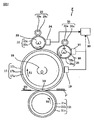
- FIG. 2 is an explanatory diagram of the configuration of the fixing device.
- a fixing device in electrophotographic image formation is a method in which a recording material and toner electrostatically carried on the recording material are nipped and conveyed by a pressure contact portion between a rotating fixing roller and a pressure roller, and then fused.
- the heat roller system is the mainstream.
- the surface of the fixing roller in order to maintain good image quality (fixability, gloss, etc.), the surface of the fixing roller is often covered with an elastic layer such as silicon rubber.
- a release layer made ofgnactrafluoroethylene (PTFE), perfluoroalkoxy (PFA) or the like is coated on the elastic layer to ensure good release properties for the melted toner.
- the pressure roller is often coated with an elastic layer such as silicon rubber in consideration of double-sided image quality, and the release layer is coated on the elastic layer using the same material as the fixing roller. Good releasability is maintained.
- a heat source such as a halogen lamp is provided inside a cylinder of a fixing roller or a pressure roller, and roller heating is performed by an inner surface heating method.
- a fixing roller having an elastic layer and a release layer is heated by an inner surface heating method, when the recording material carrying an unfixed toner image is continuously passed because the thermal conductivity of the elastic layer and the release layer is poor, the fixing roller The temperature drop on the surface becomes significant. Even if the temperature detection sensor that detects the surface temperature of the fixing roller detects the temperature drop on the surface of the fixing roller and turns on the halogen lamp, it takes a long time for the heat from the halogen lamp to reach the surface of the fixing roller. I need.
- the surface temperature of the fixing roller continues to decrease until the heat from the halogen lamp is transmitted to the roller surface, and a fixing defect occurs below the minimum fixing guarantee temperature.
- the first and second external heating rollers 22 and 25 using a material having a high heat conductivity and a built-in heat source are provided on the surface of the fixing roller 17. It is pressed against and rotated.
- An external heating method is employed in which the fixing roller is directly heated from the surface by the first and second external heating rollers 22 and 25. In the external heating method, the surfaces of the first and second external heating rollers 22 and 25 are controlled to a temperature higher than the surface of the fixing roller 17.
- the fixing device F includes a heating member (17) that is heated from the inner surface side and the surface side is in contact with the recording material, and a plurality of external heating roller members (22, 25) that rotate in contact with the surface of the heating member.
- the external heating roller member (25) positioned downstream from the position (N3) in contact with the recording material along the rotation direction of the heating member has a resistance value higher than that of the external heating roller member (22) positioned upstream. It is low.
- the first and second external heating rollers 22 and 25 are each connected to a potential (ground potential) that can be neutralized.
- the fixing roller 17 has a metal core 17a made of a metal such as aluminum or iron as a base layer, and a heat-resistant elastic layer 17b such as silicon rubber or fluorine rubber is coated on the surface thereof. Furthermore, the surface layer of the elastic layer 17b is covered with a release layer 17c composed of a heat-resistant fluorine tube.
- the fixing roller 17 is rotationally driven by a driving device (not shown) and the rotational speed is controlled.
- the release layer 17c does not contain a conductive agent such as carbon, and the surface resistivity of the surface of the fixing roller 17 is 1 ⁇ 10 15 ⁇ sq.
- the surface of the fixing roller 17, that is, the release layer of the release layer 17 c with respect to water is 110 °.
- the heating source 18 is a heat generating element such as a halogen heater disposed at the center of the fixing roller 17 and heats the inner surface of the cored bar 17 a of the fixing roller 17 by infrared rays.
- the contact type thermistor 19 contacts the surface of the fixing roller 17 and detects the surface temperature.
- the thermistor 19 may be, for example, an infrared detection type non-contact thermistor as long as it can accurately detect the surface temperature of the fixing roller 17.
- the temperature control device 20 controls the output of the heating source 18 based on the detection result of the thermistor 19 and keeps the surface temperature of the fixing roller 17 detected by the thermistor 19 within a certain temperature range.
- the pressure roller 21 is pressed against the fixing roller 17 by urging both ends of the rotating shaft toward the rotating shaft of the fixing roller 17 by a spring member (not shown), thereby forming a fixing nip N3 of the recording material S. To do.
- the pressure roller 21 is formed by covering the surface layer of the core metal 21a with the elastic layer 21b and covering the outer side with the release layer 21c.
- the pressure roller 21 may or may not have a heating source inside the cored bar 21a, but in the first embodiment, a heating source is provided for simplification. Use what you do not.
- the fixing roller 17, which is an example of a heating rotator is a roller type.
- a belt-type heating rotator is adopted as long as the fixing nip can be formed by pressing against a pressure member. May be.
- the pressure roller 21, which is an example of the heating member is a roller type.
- a belt-type heating member is used as long as it can form a fixing nip by being pressed against the fixing member. Also good. Since the elastic layer 17b on the surface of the fixing roller 17 is relatively thick and has low thermal conductivity, the amount of heat taken by the recording material S when fixing the toner image is compensated from the heating source 18 of the fixing roller 17. It becomes an obstacle when making it. In order to realize a high speed fixing device F, if only the heating source 18 of the fixing roller 17 is relied on, it is difficult to keep the surface temperature of the fixing roller 17 constant because the thermal response is not in time. .
- the first and second external heating rollers 22 and 25 are fixed to the fixing rollers so as to directly heat the surface of the heat fixing roller 17 which has been brought into contact with the recording material S and has been lowered in temperature when the toner image is fixed. It is provided in contact with By providing the two first and second external heating rollers 22 and 25, the amount of heat applied to the surface of the fixing roller 17 is increased, and the speed of the fixing device F is increased.
- the first external heating roller 22 is disposed on the upstream side in the rotation direction of the fixing roller 17 as viewed from the fixing nip N3, and is urged by a pressure mechanism (not shown) to be in pressure contact with the fixing roller 17.
- the first external heating roller 22 has a core metal 22a made of a metal such as aluminum or iron as a base layer, and a surface of which is coated with a heat-resistant fluorine-coated release layer 22c. Similar to the release layer 17 c of the fixing roller 17, the release layer 22 c of the first external heating roller 22 does not contain a conductive agent. However, since it is thinner than the release layer 17 c of the fixing roller 17, the surface resistivity of the surface of the first external heating roller 22 is 1 ⁇ 10 12 to 1 ⁇ 10 14 ⁇ sq. Further, since the release layer 22c uses a fluorine coat, the contact angle of the surface of the first external heating roller 22 with water is smaller than the contact angle of the fixing roller 17 using the fluorine tube with water.
- the surface of the external heating roller 22, that is, the release layer 22c has a contact angle with water of 95 °.
- the heating source 23 is a heat generating element such as a halogen heater included in the first external heating roller 22, and heats the inner surface of the cored bar 22 a of the first external heating roller 22 by infrared rays.
- the contact type thermistor 24 is in contact with the surface of the first external heating roller 22 to detect the surface temperature.
- the temperature control device 20 controls the output of the heating source 23 based on the detection result of the thermistor 24 to keep the surface temperature of the first external heating roller 22 detected by the thermistor 24 within a certain temperature range.
- the second external heating roller 25 is disposed on the downstream side of the first external heating roller 22 when viewed from the fixing nip N3, and is urged by a pressure mechanism (not shown) to come into pressure contact with the fixing roller 17.
- the second external heating roller 25 has a core metal 25a made of a metal such as aluminum or iron as a base layer, and the surface thereof is covered with a heat-resistant fluorine-coated release layer 25c.
- the release layer 25c of the second external heating roller 25 contains acetylene black, which is a kind of carbon, as a conductive agent.
- the proportion of the conductive agent in the release layer 25c is 7% by weight.
- the surface resistivity of the surface of the second external heating roller 25, that is, the release layer 25c is adjusted to 1 ⁇ 10 7 ⁇ / sq. Further, since the ratio of the conductive agent in the release layer 25c is larger than that of the release layer 22c of the first external heating roller 22, the contact angle of the surface of the second external heating roller 25 with respect to water is the surface of the first external heating roller 22c. Is smaller than the contact angle with water. The contact angle of the surface of the second external heating roller 25 is 85 °.
- the heating source 26 is a heat generating element such as a halogen heater included in the second external heating roller 25, and heats the inner surface of the core metal 25 a of the second external heating roller 25 by infrared rays.
- the contact type thermistor 27 is in contact with the surface of the second external heating roller 25 to detect the surface temperature.
- the temperature control device 20 controls the output of the heating source 26 based on the detection result of the thermistor 27 and keeps the surface temperature of the second external heating roller 25 detected by the thermistor 27 within a certain temperature range.
- the first and second cleaning rollers 29 and 30, which are examples of the external heating member cleaning means, are cylindrical cleaning members that rotate in pressure contact with the first and second external heating rollers 22 and 25, respectively.
- the first and second cleaning rollers 29 and 30 are formed by providing surface layers 29c and 30c such as felt, sponge, and nonwoven fabric having a rough surface property on the surfaces of the cores 29a and 30a.
- the surface temperature of the first cleaning roller 29 is lower than that of the first external heating roller 22, the toner adhering to the surface of the first external heating roller 22 in a molten state is solidified and taken into the structure of the surface layer 29c. Further, since the surface temperature of the second cleaning roller 30 is lower than that of the second external heating roller 25, the toner adhering to the surface of the second external heating roller 25 in a molten state is solidified and taken into the structure of the surface layer 30c.
- the temperature of the surface of the fixing roller 17 is adjusted to a range of 200 ° C. ⁇ 3 ° C. by the temperature control device 20.
- the temperatures of the surfaces of the first and second external heating rollers 22 and 25 are adjusted in the range of 200 ° C. to 250 ° C. according to the surface temperature of the fixing roller 17.
- the surface temperature of the pressure roller 21 heated in contact with the fixing roller 17 at the fixing nip N3 is about 150 ° C.
- the release layer 17c of the fixing roller 17 that is in direct contact with the unfixed toner image on the recording material S is to prevent an offset image defect in which the toner of the recording material S is transferred to the fixing roller 17 and the image quality is deteriorated. High releasability is required.
- the release layer 17c of the fixing roller 17 that is frequently in direct contact with the recording material S is likely to be worn out, and therefore needs to have high wear resistance. Therefore, in Example 1, the release layer 17c of “tube layer using a heat-shrinkable tube” having a high release property and wear resistance as compared with the release layer of the coated coating layer is employed. . Specifically, the release layer 17c of the fixing roller 17 is formed of a PFA tube having a thickness of 50 ⁇ m. On the other hand, the release layers 22c and 25c of the first and second external heating rollers 22 and 25 do not come into contact with the recording material S, and therefore do not require as much wear resistance as the release layer 17c of the fixing roller 17.
- the release layers 22c and 25c of the first and second external heating rollers 22 and 25 are not as high as the release layer 17c of the fixing roller 17, but have high release properties and are thermally conductive. It is required to be excellent.
- the first and second external heating rollers 22 and 25 are coated with a fluororesin material containing a conductive filler, which is an example of a conductive substance, on the surface of a conductive cylindrical material. Mold layers 22c and 25c were formed.
- the fluororesin material the release layers 22c and 25c of the first and second external heating rollers 22 and 25 can be formed by using a PTFE or PFA coating layer.
- the coating layer of PTFE or PFA has inferior surface smoothness as compared with the tube material of the same material, and although the release property is slightly inferior, the release layers 22c and 25c can be formed thin, so that high thermal conductivity and high Static neutralization can be realized.
- the release layers 22c and 25c of the first and second external heating rollers 22 and 25 are formed of a PTFE coating layer having a thickness of 10 ⁇ m.
- the surface of the fixing roller 17 covered with the insulating release layer 17c may be charged up by the conveyance of the recording material S in the fixing nip N3.
- the release layer 17c of the fixing roller 17 may be charged to a high potential through contact with the recording material S being nipped and conveyed.
- the charge-up of the release layer 17c can be prevented, but the offset is caused by the deterioration of the release property due to the deterioration of the surface smoothness of the release layer 17c due to the mixing of the conductive filler as the conductive substance. Image defects are likely to occur. Further, there is a problem that the wear resistance of the fixing roller 17 is lowered due to the deterioration of the surface smoothness and the releasability. It has also been proposed to reduce the resistance value by mixing a conductive filler into the release layer 22c of the first external heating roller 22 and to discharge the charge by connecting the cored bar 22a to the ground potential.
- the required heating performance can be exhibited in a short period of time. It turned out to be gone. That is, in order to make the surface of the first external heating roller 22 conductive, by mixing a conductive filler such as carbon black in the release layer 22c, the release property is deteriorated due to the deterioration of the surface smoothness and the wear resistance. Deterioration occurs. Furthermore, the conductive filler is equally mixed in the release layers 22c and 25c of both the first and second external heating rollers 22 and 25 to reduce the resistance value, and the core bars 22a and 25c are connected to the ground potential.
- a conductive filler such as carbon black
- Example 1 the conductive filler is dispersed in the release layer 25c of the second external heating roller 25 on the downstream side to impart conductivity, and the metal core 25c of the second external heating roller 25 is grounded. Connected to potential.
- the release layer 22c of the first external heating roller 22 is insulative because it does not contain a conductive filler, and the contact angle with water is about 110 degrees.
- the surface resistance of the fixing roller 17 with the thick release layer 17c is 1 ⁇ 10 15 ⁇ sq
- the surface resistance of the first external heating roller 22 with the thin release layer 22c is 1 ⁇ 10 12 to 1 ⁇ 10 14 ⁇ sq. Is also expensive.
- the release layer 22c of the second external heating roller 22 is adjusted to have a surface resistance of 1 ⁇ 10 7 ⁇ / sq and a contact angle with water of about 95 degrees by mixing a conductive filler. Yes.
- the releasability of the first external heating roller 22 is higher than that of the second external heating roller 25.
- a part of the toner adhering to the fixing roller 17 at the fixing nip portion N3 passes through the first external heating roller 22 and is transferred to the second external heating roller 25.
- the heating performance of the first external heating roller 22 is stably ensured over a long period of time.
- the release layer 22c of the external heating roller 22 does not contain a conductive agent, but acetylene black is contained so that the ratio of the release layer 22c is 5% by weight. It is also possible to set the surface resistivity of the layer 22c to 1 ⁇ 10 11 ⁇ / sq. ⁇ Static elimination effect>
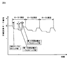
- FIG. 3 is an explanatory diagram of a change in the surface potential of the fixing roller in the fixing device of Example 1
- FIG. 4 is an explanatory diagram of a change in the surface potential of the fixing roller in the fixing device of the comparative example.
- the fixing device of the comparative example employs a second external heating roller 25 having a release layer 25c formed in the same manner as in Example 1 except that the conductive filler is not dispersed.
- the fixing device performs external heating by contacting the fixing roller 17 with the first and second external heating rollers 22 and 25 that are insulative and have no charge removal performance.
- the surface potential at one point on the surface of the fixing roller 17 is 2
- the surface potential of the fixing roller 17 increases toward the minus side due to contact with the recording material S every time it passes through the fixing nip N3 between the fixing roller 17 and the pressure roller 21.
- the release layer 17c of the fixing roller 17 and the release layer 22c of the first external heating roller 22 are in contact with each other. A little larger on the negative side due to contact.
- the release layer 25c of the second external heating roller 25 is made conductive. The surface is neutralized and the potential returns to near 0V. Since such a charging and discharging process is repeated for each rotation of the fixing roller 17, the surface potential of the fixing roller 17 rises only up to about ⁇ several hundred volts.
- the release layer 17c of the fixing roller 17 and the release layer 22c of the first external heating roller 22 are in contact with each other. A little larger on the negative side due to contact.
- the surface of the fixing roller 17 is the same as when passing through the nip portion between the fixing roller 17 and the first external heating roller 22.
- the potential increases slightly to the negative side. That is, since the release layer 25c is not conductive, the surface potential of the fixing roller 17 is slightly negative due to the contact between the release layer 17c of the fixing roller 17 and the release layer 22c of the first external heating roller 22. growing.
- the surface potential of the fixing roller 17 eventually rises to ⁇ several kV depending on the type of the recording material S, the image forming speed, the number of continuous images formed, and the atmospheric environment. There is. In this case, a scattering phenomenon occurs in which the unfixed toner image carried on the recording material S is disturbed immediately before the fixing nip N3.
- the relationship between the resistance value and contact angle of the first and second external heating rollers 22 and 25 of the first embodiment and the resistance value and contact angle of the fixing roller 17 will be described.
- the surface releasability of the first external heating roller 22 is lower than that of the fixing roller 17 but higher than that of the second external heating roller 25.
- the contact angles of the upstream first external heating member and the downstream second external heating member with water are ⁇ u and ⁇ d, respectively, and the contact angle of the heating rotator with water is ⁇ t, ⁇ t> ⁇ u> ⁇ d Meet the relationship.
- the second external heating roller 25 located on the downstream side has higher conductivity than the first external heating roller 22 located on the upstream side and is connected to the ground potential.
- the resistance values of the upstream and downstream external heating roller members are Ru and Rd, respectively, and the resistance value of the heating member is Rt, the relationship of Rt>Ru> Rd is satisfied.
- the contact angle and resistance described above were measured as follows.
- the release layer 22c of the first external heating roller 22 located upstream in the rotation direction of the fixing roller 17 with the fixing nip N3 as a starting point has a conductive filler content rate than the release layer 25c. Since it is low, it has high releasability.
- the release layer 25c of the second external heating roller 25 located upstream from the fixing nip N3 in the rotation direction of the fixing roller 17 has a higher content of the conductive filler than the release layer 22c, and thus is high. It has conductivity.
- toner and paper dust adhering to the fixing roller 17 are conveyed to the first external heating roller 22 on the upstream side by the rotation of the fixing roller 17. Since the surface of the fixing roller 17 has higher releasability than the surface of the first external heating roller 22, the toner attached to the fixing roller is transferred to the first external heating roller 22. Then, the toner that has passed through the first external heating roller 22 is transferred to the second external heating roller 25 having a lower releasability than the first external heating roller 22. With such a configuration, it is possible to prevent the deposits such as toner from concentrating on the first external heating roller 22 and to stabilize the heating capability of the first and second external heating rollers 22 and 25.
- FIG. 1 is an explanatory diagram of a configuration of the image forming apparatus according to the first embodiment.
- FIG. 2 is an explanatory diagram of the configuration of the fixing device.
- FIG. 3 is an explanatory diagram of changes in the surface potential of the fixing roller in the fixing device according to the first exemplary embodiment.
- FIG. 4 is an explanatory diagram of changes in the surface potential of the fixing roller in the fixing device of the comparative example.
- an image heating apparatus using a plurality of external heating members it is possible to provide an image heating apparatus that can maintain the heating performance of the external heating members over a long period of time.
Landscapes
- Physics & Mathematics (AREA)
- General Physics & Mathematics (AREA)
- Fixing For Electrophotography (AREA)
Abstract
記録材上のトナー像を加熱二ツプ部で加熱する加熱回転体と;前記加熱回転体に接触し、前記加熱二ップ部を形成する加圧回転体と;前記加熱二ツプ部を通過した前記加熱回転体の外周面に接し、前記外周面を加熱する第1外部加熱部材であって、前記外周面と接触する面に離型層を具備する第1外部加熱部材と;前記第1外部加熱部材で加熱された前記外周面を加熱する第2外部加熱部材であって、前記第2外部加熱部材の前記外周面と接触する面に導電剤を含む離型層を具備する第2外部加熱部材とを有し、前記第1外部加熱部材の離型層の水に対する接触角は、前記第2外部加熱部材の離型層の水に対する接触角よりも大きく、前記第2外部加熱部材の表面抵抗は前記第1外部加熱部材の表面抵抗よりも低いことを特徴とする画像形成装置。
Description
本発明は、記録材上の画像に接する加熱回転体の表面に当接させて複数の外部加熱部材を配置した画像加熱装置、詳しくは外部加熱部材の表面の加熱性能を長持ちさせる構造に関する。
外周面が記録材上の画像に接する加熱回転体(定着ローラ、定着ベルト、加圧ローラ、加圧ベルト)に加圧部材を圧接して、記録材を挟持するニップ部を形成した画像加熱装置が広く用いられている。画像加熱装置の一例である定着装置では、トナー像を転写された記録材が、定着ニップで挟持して搬送される過程で加熱・加圧を受けて、トナー像が融解・押潰されることにより記録材の表面に画像として定着される。
このような定着装置で定着速度を高めようとすると、記録材との接触に伴う加熱回転体の表面温度の低下を、内面側からの加熱だけでは賄いきれなくなる。また、定着装置の起動後に加熱回転体の表面温度が必要な温度に達するまでの時間を短縮することも求められている。
このため、特開2004−37555号公報では、加熱回転体の外周面に当接して回転して加熱部材の表面を直接加熱する外部加熱部材を、記録材に接する位置から加熱回転体の回転方向に沿って複数配置した定着装置が実用化されている。
また、加熱回転体の外周面には、融解したトナーからの離型性を高めるための離型層が形成されているため、抵抗が高く、記録材との接触に伴って帯電し易くなっている。
このような定着装置で定着速度を高めようとすると、記録材との接触頻度が高まって加熱回転体の外周面が過剰な電位まで帯電してしまい、記録材上に担持された未定着トナー像を乱して画像品質を低下させる可能性がある。
そこで、特開2002−62752号公報には、表面に形成された離型層に導電性物質を含有させて抵抗値を低くした外部加熱部材を接地電位に接続して、加熱回転体の外周面を除電させるようにした定着装置が示される。
特開2002−62752号公報に示されるように、外部加熱部材の離型層に導電性物質を含有させると、離型層の離型性が低下してしまい、外部加熱部材の表面が汚れ易くなって溶融したトナー等が連れ回り易くなる。その結果、外部加熱部材と加熱回転体との正常な接触状態が損なわれて、本来の加熱性能を発揮できなくなる。
特に、特開2004−37555号公報に開示されるように複数の外部加熱部材を設ける場合、定着ニップ部で加熱回転体に付着したトナーが初めに接触する加熱回転体の回転方向の上流側の外部加熱部材は、汚れが集中するため、短期間で加熱性能が損なわれてしまう。
このような定着装置で定着速度を高めようとすると、記録材との接触に伴う加熱回転体の表面温度の低下を、内面側からの加熱だけでは賄いきれなくなる。また、定着装置の起動後に加熱回転体の表面温度が必要な温度に達するまでの時間を短縮することも求められている。
このため、特開2004−37555号公報では、加熱回転体の外周面に当接して回転して加熱部材の表面を直接加熱する外部加熱部材を、記録材に接する位置から加熱回転体の回転方向に沿って複数配置した定着装置が実用化されている。
また、加熱回転体の外周面には、融解したトナーからの離型性を高めるための離型層が形成されているため、抵抗が高く、記録材との接触に伴って帯電し易くなっている。
このような定着装置で定着速度を高めようとすると、記録材との接触頻度が高まって加熱回転体の外周面が過剰な電位まで帯電してしまい、記録材上に担持された未定着トナー像を乱して画像品質を低下させる可能性がある。
そこで、特開2002−62752号公報には、表面に形成された離型層に導電性物質を含有させて抵抗値を低くした外部加熱部材を接地電位に接続して、加熱回転体の外周面を除電させるようにした定着装置が示される。
特開2002−62752号公報に示されるように、外部加熱部材の離型層に導電性物質を含有させると、離型層の離型性が低下してしまい、外部加熱部材の表面が汚れ易くなって溶融したトナー等が連れ回り易くなる。その結果、外部加熱部材と加熱回転体との正常な接触状態が損なわれて、本来の加熱性能を発揮できなくなる。
特に、特開2004−37555号公報に開示されるように複数の外部加熱部材を設ける場合、定着ニップ部で加熱回転体に付着したトナーが初めに接触する加熱回転体の回転方向の上流側の外部加熱部材は、汚れが集中するため、短期間で加熱性能が損なわれてしまう。
本発明は、外部加熱部材を複数用いる画像加熱装置において、外部加熱部材による加熱性能を長期間に渡って維持できる画像加熱装置を提供することを目的としている。
本発明は、記録材上のトナー像を加熱ニップ部で加熱する加熱回転体と;前記加熱回転体に接触し、前記加熱ニップ部を形成する加圧回転体と;前記加熱ニップ部を通過した前記加熱回転体の外周面に接し、前記外周面を加熱する第1外部加熱部材であって、前記外周面と接触する面に離型層を具備する第1外部加熱部材と;前記第1外部加熱部材で加熱された前記外周面を加熱する第2外部加熱部材であって、前記第2外部加熱部材の前記外周面と接触する面に導電剤を含む離型層を具備する第2外部加熱部材とを有し、前記第1外部加熱部材の離型層の水に対する接触角は、前記第2外部加熱部材の離型層の水に対する接触角よりも大きく、前記第2外部加熱部材の表面抵抗は前記第1外部加熱部材の表面抵抗よりも低いことを特徴とする画像形成装置を提供する。
また、本発明は、記録材上のトナー像を加熱ニップ部で加熱する加熱回転体と;前記加熱回転体に接触し、前記加熱ニップ部を形成する加圧回転体と;前記加熱ニップ部を通過した前記加熱回転体の外周面に接し、前記外周面を加熱する第1外部加熱部材であって、前記第1外部加熱部材の前記外周面と接触する面に離型層を具備する第1外部加熱部材と;前記第1外部加熱部材で加熱された前記外周面を加熱する第2外部加熱部材であって、前記第2外部加熱部材の前記外周面と接触する面に導電剤を含む離型層を具備する第2外部加熱部材と;を有し、前記第1外部加熱部材の離型層の水に対する接触角は、前記第2外部加熱部材の離型層の水に対する接触角よりも大きく、前記第2外部加熱部材の前記離型層を占める前記導電剤の割合は、前記第2外部加熱部材の前記離型層を占める前記導電剤の割合よりも大きいことを特徴とする画像形成装置を提供する。
以下、本発明のいくつかの実施形態を、図面を参照して詳細に説明する。本発明は、下流側の外部加熱部材が上流側の外部加熱部材よりも低抵抗である限りにおいて、各実施形態の構成の一部または全部を、その代替的な構成で置き換えた別の実施形態でも実施できる。
本実施形態では、未定着トナー像を記録材に定着させる定着装置について説明するが、本発明は、定着済み画像又は半定着画像を担持した記録材を加熱加圧して画像の表面性状を調整する加熱処理装置としても実施できる。
なお、特許文献1に示される画像形成装置及び定着装置の一般的な事項については、図示を省略して重複する説明を省略する。また、請求項で用いた構成名に括弧を付して示した参照記号は、発明の理解を助けるための例示であって、実施形態中の該当する部材等に構成を限定する趣旨のものではない。
<画像形成装置>
図1は第1実施形態の画像形成装置の構成の説明図である。
図1に示すように、画像形成装置100は、中間転写ベルト6に沿ってイエロー、マゼンタ、シアン、ブラックの画像形成部Y、C、M、Kを配置したタンデム型フルカラーレーザプリンタである。
画像形成部Y、C、M、Kは、下から上に順にトナー像を中間転写ベルト6へ転写するように配置され、それぞれ電子写真プロセスを用いてトナー像が形成される感光ドラム1を備えている。それぞれの感光ドラム1の周囲には、感光ドラム1の回転方向に沿って帯電装置2、現像装置3、一次転写ローラ9、及びクリーニング装置4が配置されている。露光装置5は、画像形成部Y、C、M、Kの感光ドラム1に対して、レーザー走査露光光学系を用いて共通に露光を行うように配置されている。
画像形成部Y、C、M、Kにおいて、露光装置5により、画像データに基づいた走査露光が、帯電装置2によって一様に帯電された感光ドラム1上になされて、感光ドラム1表面に走査露光画像に対応する静電像が形成される。
現像装置3は、感光ドラム1の表面に形成された静電像を、トナー像として現像する。画像形成部Yの現像装置3にはイエロートナー、画像形成部Cの現像器3にはシアントナー、画像形成部Mの現像器3にはマゼンタトナー、画像形成部Kの現像器3にはブラックトナーがそれぞれ充填されている。このため、画像形成部Yの感光ドラム1にはイエロートナー像が、画像形成部Cの感光ドラム1にはシアントナー像が、画像形成部Mの感光ドラム1にはマゼンタトナー像が、画像形成部Kの感光ドラム1にはブラックトナー像がそれぞれ形成される。
画像形成部Y、C、M、Kのそれぞれの感光ドラム1に現像された上記各色の単色トナー像は、感光ドラム1の回転と同期して等速で回転する中間転写ベルト6へ所定の位置合わせ状態で順に重畳されるように一次転写される。これにより、中間転写ベルト6上に、未定着のフルカラートナー像が合成形成される。
第1実施形態では、エンドレスの中間転写ベルト6を用いており、中間転写ベルト6は、駆動ローラ7、二次転写対向ローラ14、テンションローラ8に懸回して張架され、駆動ローラ7によって回転駆動される。
画像形成部Y、C、M、Kのそれぞれの一次転写ローラ9は、感光ドラム1に向かって中間転写ベルト6を付勢して、感光ドラム1と中間転写ベルト6との間にトナー像の一次転写部を形成する。
不図示のバイアス電源が一次転写ローラ9に対してトナー像と逆極性の一次転写バイアスを印加する。これにより、画像形成部Y、C、M、Kの感光ドラム1から中間転写ベルト6に対して、各色のトナー画像が一次転写される。
画像形成部Y、C、M、Kにおいて感光ドラム1から中間転写ベルト6へトナー像を一次転写した後に、感光ドラム1上に残った転写残トナーは、クリーニング装置4によって除去される。
このような工程を中間転写ベルト6の回転に同調して、イエロー、シアン、マゼンタ、ブラックの画像形成部Y、C、M、Kで行うことにより、中間転写ベルト6上に各色のトナー像が順次重ねて一次転写される。なお、単色のみの画像形成(単色モード)時には、上記工程は、目的の色の画像形成部(例えばブラックの画像形成部K)についてのみ行われる。
一方、記録材カセット10にセットされた記録材Sは、給送ローラ11によって一枚分離給送されて、搬送路10aを通って、レジストローラ12に先端を当接した状態で停止する。記録材Sは、中央基準にて搬送される。レジストローラ12は、所定の制御タイミングで起動して、中間転写ベルト6と二次転写ローラ13とのニップ部である二次転写部へ記録材Sを送り込む。
二次転写ローラ13は、接地電位に接続された二次転写対向ローラ14に内側から支持された中間転写ベルト6に当接して記録材Sに対するトナー像の二次転写部を形成する。中間転写ベルト6上に一次転写して重ね合わせたトナー像は、不図示のバイアス電源がトナーと逆極性のバイアスを二次転写ローラ13に印加することにより、記録材S上に一括二次転写される。
二次転写部を通過した中間転写ベルト6上に残った二次転写残トナーは、ベルトクリーニング装置15によって除去される。
トナー像を二次転写された記録材Sは、中間転写ベルト6から曲率分離され、搬送路10bを通って画像加熱装置の一例である定着装置Fに導入される。定着装置Fは、トナー像が二次転写された記録材を加熱・加圧しつつ挟持搬送する過程で、トナー像を融解、押潰して記録材S上にフルカラー画像を定着させる。
定着装置Fから送り出された記録材Sは、搬送路10cを通って、フルカラープリント、もしくはモノカラープリントとして、排紙トレイ16に排紙される。
<画像加熱装置>
図2は定着装置の構成の説明図である。
電子写真方式の画像形成における定着装置は、記録材と、静電的に記録材に担持されたトナーとを、回転している定着ローラと加圧ローラとの圧接部で挟持搬送して溶融定着させる熱ローラ方式が主流である。
熱ローラ方式では、画像品質(定着性と光沢感など)を良好に保つために、定着ローラの表面にシリコンゴム等の弾性層を被覆して用いることが多い。そして、弾性層の上にパーテトラフロロエチレン(PTFE)やパーフロロアルコキシ(PFA)等からなる離型層を被覆して溶融したトナーに対する良好な離型性を確保している。
また、加圧ローラも、両面画像品質を考慮してシリコンゴム等の弾性層が被覆されることが多く、弾性層の上に定着ローラと同様な材料を用いて離型層を被覆することで良好な離型性を保っている。
熱ローラ方式は、定着ローラや加圧ローラのシリンダ内部にハロゲンランプ等の熱源を設け、内面加熱方式によるローラ加熱を行っている。弾性層及び離型層を有する定着ローラを内面加熱方式で加熱する場合、弾性層及び離型層の熱伝導性が悪いため、未定着トナー像を担持した記録材を連続通過させた場合定着ローラ表面の温度低下が著しくなる。
定着ローラの表面温度を検知する温度検知センサが、定着ローラ表面の温度低下を検知してハロゲンランプを点灯させても、ハロゲンランプからの熱が定着ローラの表面に到達するまでに多くの時間を必要とする。このため、定着ローラの表面温度は、ハロゲンランプからの熱がローラ表面に伝達されるまで低下し続け、最低定着保証温度を下回って定着不良が発生してしまう。
図2に示すように、そこで、第1実施形態の定着装置Fでは、熱源を内蔵して熱伝導率の高い物質を用いた第1及び第2外部加熱ローラ22、25を定着ローラ17の表面に圧接して回転させている。定着ローラを第1及び第2外部加熱ローラ22、25によって表面から直接加熱する外部加熱方式が採用されている。
外部加熱方式では、第1及び第2外部加熱ローラ22、25の表面は、定着ローラ17の表面よりも高い温度に制御される。第1及び第2外部加熱ローラ22、25と定着ローラ17との圧接ニップ部では、外部加熱ローラ22、25から定着ローラ17の表面へ直接伝熱するため、内面加熱方式に比べて定着ローラ17の温度低下を効果的に防止できる。
定着装置Fは、内面側から加熱されて表面側が記録材に接する加熱部材(17)と、加熱部材の表面に当接して回転する複数の外部加熱ローラ部材(22、25)とを備える。そして、記録材に接する位置(N3)から加熱部材の回転方向に沿って下流側に位置する外部加熱ローラ部材(25)は、上流側に位置する外部加熱ローラ部材(22)よりも抵抗値を低くしている。また、第1及び第2外部加熱ローラ22、25は、各々、除電可能な電位(接地電位)に接続されている。
定着ローラ17は、アルミニウムや鉄等の金属でできた芯金17aを基層とし、その表面にシリコンゴムやフッ素ゴム等の耐熱性の弾性層17bを被覆している。更に、弾性層17bの表層には、耐熱性のフッ素チューブで構成される離型層17cが被覆されている。定着ローラ17は、不図示の駆動装置によって回転駆動されて回転速度を制御されている。
離型層17cは、カーボンなどの導電剤は含まれておらず、定着ローラ17の表面の表面抵抗率は1×10¹⁵Ωsqである。また、離型層17cとしてフッ素チューブを用いることによって、表面は高い離型性を確保している。定着ローラ17の表面、つまり、離型層17cの離型層の水に対する接触角は110°である。なお、水に対する接触角が大きいほどトナーに対する離型性は高くなる。
加熱源18は、定着ローラ17の中心に配置したハロゲンヒータ等の熱発生素子であって、定着ローラ17の芯金17aの内側面を赤外線加熱する。
接触式のサーミスタ19は、定着ローラ17の表面に接触して表面温度を検知する。サーミスタ19は、定着ローラ17の表面温度を正確に検知できるものであれば、例えば赤外線検知型の非接触サーミスタであっても良い。
温度制御装置20は、サーミスタ19の検知結果に基づいて加熱源18の出力を制御して、サーミスタ19によって検知される定着ローラ17の表面温度を、或る一定の温度範囲に収める。
加圧ローラ21は、回転軸の両端が不図示のバネ部材によって定着ローラ17の回転軸に向かって付勢されることにより、定着ローラ17に圧接して、記録材Sの定着ニップN3を形成する。加圧ローラ21は、定着ローラ17と同様に、芯金21aの表層を弾性層21bにより被覆し、その外側を離型層21cにより被覆して形成される。
ここで、加圧ローラ21は、芯金21aの内部に加熱源を有するものであっても、有さないものであっても良いが、第1実施形態では、簡略化のため加熱源を有さないものを用いる。
また、第1実施形態においては、加熱回転体の一例である定着ローラ17がローラタイプであるが、加圧部材に圧接して定着ニップを形成できるものであれば、ベルト式加熱回転体を採用してもよい。
また、第1実施形態においては、加熱部材の一例である加圧ローラ21がローラタイプであるが、定着部材に圧接して定着ニップを形成できるものであれば、ベルト式加熱部材を採用してもよい。
定着ロ−ラ17の表面の弾性層17bは、比較的に厚くて熱伝導性が低いため、トナー像の定着時に記録材Sに奪われる熱量を、定着ロ−ラ17の加熱源18から補わせる際の障害となる。定着装置Fの高速化を実現するためには、定着ロ−ラ17の加熱源18だけに頼っていては、熱応答が間に合わなくなって定着ローラ17の表面温度を一定に保つことが困難である。
このため、トナー像の定着時に記録材Sに接触して温度低下した熱定着ロ−ラ17の表面を直接加熱するように、第1及び第2外部加熱ロ−ラ22、25を定着ロ−ラ17に当接させて設けている。2本の第1及び第2外部加熱ロ−ラ22、25を設けることにより、定着ロ−ラ17の表面に与える熱量を増やして定着装置Fの高速化を実現している。
第1外部加熱ローラ22は、定着ニップN3から見て、定着ローラ17の回転方向の上流側に配設され、不図示の加圧機構に付勢されて定着ローラ17に圧接する。第1外部加熱ローラ22は、アルミニウムや鉄等の金属でできた芯金22aを基層として、その表面に耐熱性のフッ素コートの離型層22cを被覆してある。
第1外部加熱ローラ22の離型層22cは、定着ローラ17の離型層17cと同様に、導電剤は含まれていない。しかし、定着ローラ17の離型層17cよりも薄いため、第1外部加熱ローラ22の表面の表面抵抗率は1×10¹²~1×10¹⁴Ωsqである。
また、離型層22cはフッ素コートを用いているため、第1外部加熱ローラ22の表面の水に対する接触角は、フッ素チューブを用いる定着ローラ17の水に対する接触角よりも小さくなっている。外部加熱ローラ22の表面、つまり、離型層22cは、水に対する接触角が95°である。
加熱源23は、第1外部加熱ローラ22に内包されたハロゲンヒータ等の熱発生素子であって、第1外部加熱ローラ22の芯金22aの内側面を赤外線加熱する。
接触式のサーミスタ24は、第1外部加熱ローラ22の表面に接触して表面温度を検知する。
温度制御装置20は、サーミスタ24の検知結果に基づいて加熱源23の出力を制御して、サーミスタ24によって検知される第1外部加熱ローラ22の表面温度を、或る一定の温度範囲に収める。
第2外部加熱ローラ25は、定着ニップN3から見て、第1外部加熱ローラ22よりも下流側に配設され、不図示の加圧機構に付勢されて定着ローラ17に圧接する。第2外部加熱ローラ25は、アルミニウムや鉄等の金属でできた芯金25aを基層として、その表面に耐熱性のフッ素コートの離型層25cを被覆してある。
第2外部加熱ローラ25の離型層25cは、カーボンの一種であるアセチレンブラックを導電剤として含んでいる。離型層25cに導電剤が占める割合は7重量%である。
導電剤の含有によって、第2外部加熱ローラ25の表面、つまり、離型層25cの表面抵抗率は1×10⁷Ω/sqに調整されている。また、離型層25cにおける導電剤の割合は第1外部加熱ローラ22の離型層22cよりも多いため、第2外部加熱ローラ25の表面の水に対する接触角は第1外部加熱ローラ22cの表面の水に対する接触角よりも小さい。
第2外部加熱ローラ25の表面の接触角は85°である。
加熱源26は、第2外部加熱ローラ25に内包されたハロゲンヒータ等の熱発生素子であって、第2外部加熱ローラ25の芯金25aの内側面を赤外線加熱する。
接触式のサーミスタ27は、第2外部加熱ローラ25の表面に接触して表面温度を検知する。
温度制御装置20は、サーミスタ27の検知結果に基づいて加熱源26の出力を制御して、サーミスタ27によって検知される第2外部加熱ローラ25の表面温度を、或る一定の温度範囲に収める。
外部加熱部材クリーニング手段の一例である第1及び第2清掃ローラ29、30は、第1及び第2外部加熱ローラ22、25にそれぞれ圧接して回転する円筒状の清掃部材である。第1及び第2清掃ローラ29、30は、芯金29a、30aの表面に、粗い表面性状を有する耐熱材料、例えばフェルト、スポンジ、不織布等の表層29c、30cを設けて形成される。
第1清掃ローラ29は、第1外部加熱ローラ22よりも表面温度が低いため、第1外部加熱ローラ22の表面に溶融状態で付着したトナーを固化して表層29cの組織に取り込む。また、第2清掃ローラ30は、第2外部加熱ローラ25よりも表面温度が低いため、第2外部加熱ローラ25の表面に溶融状態で付着したトナーを固化して表層30cの組織に取り込む。
本発明は、記録材上のトナー像を加熱ニップ部で加熱する加熱回転体と;前記加熱回転体に接触し、前記加熱ニップ部を形成する加圧回転体と;前記加熱ニップ部を通過した前記加熱回転体の外周面に接し、前記外周面を加熱する第1外部加熱部材であって、前記外周面と接触する面に離型層を具備する第1外部加熱部材と;前記第1外部加熱部材で加熱された前記外周面を加熱する第2外部加熱部材であって、前記第2外部加熱部材の前記外周面と接触する面に導電剤を含む離型層を具備する第2外部加熱部材とを有し、前記第1外部加熱部材の離型層の水に対する接触角は、前記第2外部加熱部材の離型層の水に対する接触角よりも大きく、前記第2外部加熱部材の表面抵抗は前記第1外部加熱部材の表面抵抗よりも低いことを特徴とする画像形成装置を提供する。
また、本発明は、記録材上のトナー像を加熱ニップ部で加熱する加熱回転体と;前記加熱回転体に接触し、前記加熱ニップ部を形成する加圧回転体と;前記加熱ニップ部を通過した前記加熱回転体の外周面に接し、前記外周面を加熱する第1外部加熱部材であって、前記第1外部加熱部材の前記外周面と接触する面に離型層を具備する第1外部加熱部材と;前記第1外部加熱部材で加熱された前記外周面を加熱する第2外部加熱部材であって、前記第2外部加熱部材の前記外周面と接触する面に導電剤を含む離型層を具備する第2外部加熱部材と;を有し、前記第1外部加熱部材の離型層の水に対する接触角は、前記第2外部加熱部材の離型層の水に対する接触角よりも大きく、前記第2外部加熱部材の前記離型層を占める前記導電剤の割合は、前記第2外部加熱部材の前記離型層を占める前記導電剤の割合よりも大きいことを特徴とする画像形成装置を提供する。
以下、本発明のいくつかの実施形態を、図面を参照して詳細に説明する。本発明は、下流側の外部加熱部材が上流側の外部加熱部材よりも低抵抗である限りにおいて、各実施形態の構成の一部または全部を、その代替的な構成で置き換えた別の実施形態でも実施できる。
本実施形態では、未定着トナー像を記録材に定着させる定着装置について説明するが、本発明は、定着済み画像又は半定着画像を担持した記録材を加熱加圧して画像の表面性状を調整する加熱処理装置としても実施できる。
なお、特許文献1に示される画像形成装置及び定着装置の一般的な事項については、図示を省略して重複する説明を省略する。また、請求項で用いた構成名に括弧を付して示した参照記号は、発明の理解を助けるための例示であって、実施形態中の該当する部材等に構成を限定する趣旨のものではない。
<画像形成装置>
図1は第1実施形態の画像形成装置の構成の説明図である。
図1に示すように、画像形成装置100は、中間転写ベルト6に沿ってイエロー、マゼンタ、シアン、ブラックの画像形成部Y、C、M、Kを配置したタンデム型フルカラーレーザプリンタである。
画像形成部Y、C、M、Kは、下から上に順にトナー像を中間転写ベルト6へ転写するように配置され、それぞれ電子写真プロセスを用いてトナー像が形成される感光ドラム1を備えている。それぞれの感光ドラム1の周囲には、感光ドラム1の回転方向に沿って帯電装置2、現像装置3、一次転写ローラ9、及びクリーニング装置4が配置されている。露光装置5は、画像形成部Y、C、M、Kの感光ドラム1に対して、レーザー走査露光光学系を用いて共通に露光を行うように配置されている。
画像形成部Y、C、M、Kにおいて、露光装置5により、画像データに基づいた走査露光が、帯電装置2によって一様に帯電された感光ドラム1上になされて、感光ドラム1表面に走査露光画像に対応する静電像が形成される。
現像装置3は、感光ドラム1の表面に形成された静電像を、トナー像として現像する。画像形成部Yの現像装置3にはイエロートナー、画像形成部Cの現像器3にはシアントナー、画像形成部Mの現像器3にはマゼンタトナー、画像形成部Kの現像器3にはブラックトナーがそれぞれ充填されている。このため、画像形成部Yの感光ドラム1にはイエロートナー像が、画像形成部Cの感光ドラム1にはシアントナー像が、画像形成部Mの感光ドラム1にはマゼンタトナー像が、画像形成部Kの感光ドラム1にはブラックトナー像がそれぞれ形成される。
画像形成部Y、C、M、Kのそれぞれの感光ドラム1に現像された上記各色の単色トナー像は、感光ドラム1の回転と同期して等速で回転する中間転写ベルト6へ所定の位置合わせ状態で順に重畳されるように一次転写される。これにより、中間転写ベルト6上に、未定着のフルカラートナー像が合成形成される。
第1実施形態では、エンドレスの中間転写ベルト6を用いており、中間転写ベルト6は、駆動ローラ7、二次転写対向ローラ14、テンションローラ8に懸回して張架され、駆動ローラ7によって回転駆動される。
画像形成部Y、C、M、Kのそれぞれの一次転写ローラ9は、感光ドラム1に向かって中間転写ベルト6を付勢して、感光ドラム1と中間転写ベルト6との間にトナー像の一次転写部を形成する。
不図示のバイアス電源が一次転写ローラ9に対してトナー像と逆極性の一次転写バイアスを印加する。これにより、画像形成部Y、C、M、Kの感光ドラム1から中間転写ベルト6に対して、各色のトナー画像が一次転写される。
画像形成部Y、C、M、Kにおいて感光ドラム1から中間転写ベルト6へトナー像を一次転写した後に、感光ドラム1上に残った転写残トナーは、クリーニング装置4によって除去される。
このような工程を中間転写ベルト6の回転に同調して、イエロー、シアン、マゼンタ、ブラックの画像形成部Y、C、M、Kで行うことにより、中間転写ベルト6上に各色のトナー像が順次重ねて一次転写される。なお、単色のみの画像形成(単色モード)時には、上記工程は、目的の色の画像形成部(例えばブラックの画像形成部K)についてのみ行われる。
一方、記録材カセット10にセットされた記録材Sは、給送ローラ11によって一枚分離給送されて、搬送路10aを通って、レジストローラ12に先端を当接した状態で停止する。記録材Sは、中央基準にて搬送される。レジストローラ12は、所定の制御タイミングで起動して、中間転写ベルト6と二次転写ローラ13とのニップ部である二次転写部へ記録材Sを送り込む。
二次転写ローラ13は、接地電位に接続された二次転写対向ローラ14に内側から支持された中間転写ベルト6に当接して記録材Sに対するトナー像の二次転写部を形成する。中間転写ベルト6上に一次転写して重ね合わせたトナー像は、不図示のバイアス電源がトナーと逆極性のバイアスを二次転写ローラ13に印加することにより、記録材S上に一括二次転写される。
二次転写部を通過した中間転写ベルト6上に残った二次転写残トナーは、ベルトクリーニング装置15によって除去される。
トナー像を二次転写された記録材Sは、中間転写ベルト6から曲率分離され、搬送路10bを通って画像加熱装置の一例である定着装置Fに導入される。定着装置Fは、トナー像が二次転写された記録材を加熱・加圧しつつ挟持搬送する過程で、トナー像を融解、押潰して記録材S上にフルカラー画像を定着させる。
定着装置Fから送り出された記録材Sは、搬送路10cを通って、フルカラープリント、もしくはモノカラープリントとして、排紙トレイ16に排紙される。
<画像加熱装置>
図2は定着装置の構成の説明図である。
電子写真方式の画像形成における定着装置は、記録材と、静電的に記録材に担持されたトナーとを、回転している定着ローラと加圧ローラとの圧接部で挟持搬送して溶融定着させる熱ローラ方式が主流である。
熱ローラ方式では、画像品質(定着性と光沢感など)を良好に保つために、定着ローラの表面にシリコンゴム等の弾性層を被覆して用いることが多い。そして、弾性層の上にパーテトラフロロエチレン(PTFE)やパーフロロアルコキシ(PFA)等からなる離型層を被覆して溶融したトナーに対する良好な離型性を確保している。
また、加圧ローラも、両面画像品質を考慮してシリコンゴム等の弾性層が被覆されることが多く、弾性層の上に定着ローラと同様な材料を用いて離型層を被覆することで良好な離型性を保っている。
熱ローラ方式は、定着ローラや加圧ローラのシリンダ内部にハロゲンランプ等の熱源を設け、内面加熱方式によるローラ加熱を行っている。弾性層及び離型層を有する定着ローラを内面加熱方式で加熱する場合、弾性層及び離型層の熱伝導性が悪いため、未定着トナー像を担持した記録材を連続通過させた場合定着ローラ表面の温度低下が著しくなる。
定着ローラの表面温度を検知する温度検知センサが、定着ローラ表面の温度低下を検知してハロゲンランプを点灯させても、ハロゲンランプからの熱が定着ローラの表面に到達するまでに多くの時間を必要とする。このため、定着ローラの表面温度は、ハロゲンランプからの熱がローラ表面に伝達されるまで低下し続け、最低定着保証温度を下回って定着不良が発生してしまう。
図2に示すように、そこで、第1実施形態の定着装置Fでは、熱源を内蔵して熱伝導率の高い物質を用いた第1及び第2外部加熱ローラ22、25を定着ローラ17の表面に圧接して回転させている。定着ローラを第1及び第2外部加熱ローラ22、25によって表面から直接加熱する外部加熱方式が採用されている。
外部加熱方式では、第1及び第2外部加熱ローラ22、25の表面は、定着ローラ17の表面よりも高い温度に制御される。第1及び第2外部加熱ローラ22、25と定着ローラ17との圧接ニップ部では、外部加熱ローラ22、25から定着ローラ17の表面へ直接伝熱するため、内面加熱方式に比べて定着ローラ17の温度低下を効果的に防止できる。
定着装置Fは、内面側から加熱されて表面側が記録材に接する加熱部材(17)と、加熱部材の表面に当接して回転する複数の外部加熱ローラ部材(22、25)とを備える。そして、記録材に接する位置(N3)から加熱部材の回転方向に沿って下流側に位置する外部加熱ローラ部材(25)は、上流側に位置する外部加熱ローラ部材(22)よりも抵抗値を低くしている。また、第1及び第2外部加熱ローラ22、25は、各々、除電可能な電位(接地電位)に接続されている。
定着ローラ17は、アルミニウムや鉄等の金属でできた芯金17aを基層とし、その表面にシリコンゴムやフッ素ゴム等の耐熱性の弾性層17bを被覆している。更に、弾性層17bの表層には、耐熱性のフッ素チューブで構成される離型層17cが被覆されている。定着ローラ17は、不図示の駆動装置によって回転駆動されて回転速度を制御されている。
離型層17cは、カーボンなどの導電剤は含まれておらず、定着ローラ17の表面の表面抵抗率は1×10¹⁵Ωsqである。また、離型層17cとしてフッ素チューブを用いることによって、表面は高い離型性を確保している。定着ローラ17の表面、つまり、離型層17cの離型層の水に対する接触角は110°である。なお、水に対する接触角が大きいほどトナーに対する離型性は高くなる。
加熱源18は、定着ローラ17の中心に配置したハロゲンヒータ等の熱発生素子であって、定着ローラ17の芯金17aの内側面を赤外線加熱する。
接触式のサーミスタ19は、定着ローラ17の表面に接触して表面温度を検知する。サーミスタ19は、定着ローラ17の表面温度を正確に検知できるものであれば、例えば赤外線検知型の非接触サーミスタであっても良い。
温度制御装置20は、サーミスタ19の検知結果に基づいて加熱源18の出力を制御して、サーミスタ19によって検知される定着ローラ17の表面温度を、或る一定の温度範囲に収める。
加圧ローラ21は、回転軸の両端が不図示のバネ部材によって定着ローラ17の回転軸に向かって付勢されることにより、定着ローラ17に圧接して、記録材Sの定着ニップN3を形成する。加圧ローラ21は、定着ローラ17と同様に、芯金21aの表層を弾性層21bにより被覆し、その外側を離型層21cにより被覆して形成される。
ここで、加圧ローラ21は、芯金21aの内部に加熱源を有するものであっても、有さないものであっても良いが、第1実施形態では、簡略化のため加熱源を有さないものを用いる。
また、第1実施形態においては、加熱回転体の一例である定着ローラ17がローラタイプであるが、加圧部材に圧接して定着ニップを形成できるものであれば、ベルト式加熱回転体を採用してもよい。
また、第1実施形態においては、加熱部材の一例である加圧ローラ21がローラタイプであるが、定着部材に圧接して定着ニップを形成できるものであれば、ベルト式加熱部材を採用してもよい。
定着ロ−ラ17の表面の弾性層17bは、比較的に厚くて熱伝導性が低いため、トナー像の定着時に記録材Sに奪われる熱量を、定着ロ−ラ17の加熱源18から補わせる際の障害となる。定着装置Fの高速化を実現するためには、定着ロ−ラ17の加熱源18だけに頼っていては、熱応答が間に合わなくなって定着ローラ17の表面温度を一定に保つことが困難である。
このため、トナー像の定着時に記録材Sに接触して温度低下した熱定着ロ−ラ17の表面を直接加熱するように、第1及び第2外部加熱ロ−ラ22、25を定着ロ−ラ17に当接させて設けている。2本の第1及び第2外部加熱ロ−ラ22、25を設けることにより、定着ロ−ラ17の表面に与える熱量を増やして定着装置Fの高速化を実現している。
第1外部加熱ローラ22は、定着ニップN3から見て、定着ローラ17の回転方向の上流側に配設され、不図示の加圧機構に付勢されて定着ローラ17に圧接する。第1外部加熱ローラ22は、アルミニウムや鉄等の金属でできた芯金22aを基層として、その表面に耐熱性のフッ素コートの離型層22cを被覆してある。
第1外部加熱ローラ22の離型層22cは、定着ローラ17の離型層17cと同様に、導電剤は含まれていない。しかし、定着ローラ17の離型層17cよりも薄いため、第1外部加熱ローラ22の表面の表面抵抗率は1×10¹²~1×10¹⁴Ωsqである。
また、離型層22cはフッ素コートを用いているため、第1外部加熱ローラ22の表面の水に対する接触角は、フッ素チューブを用いる定着ローラ17の水に対する接触角よりも小さくなっている。外部加熱ローラ22の表面、つまり、離型層22cは、水に対する接触角が95°である。
加熱源23は、第1外部加熱ローラ22に内包されたハロゲンヒータ等の熱発生素子であって、第1外部加熱ローラ22の芯金22aの内側面を赤外線加熱する。
接触式のサーミスタ24は、第1外部加熱ローラ22の表面に接触して表面温度を検知する。
温度制御装置20は、サーミスタ24の検知結果に基づいて加熱源23の出力を制御して、サーミスタ24によって検知される第1外部加熱ローラ22の表面温度を、或る一定の温度範囲に収める。
第2外部加熱ローラ25は、定着ニップN3から見て、第1外部加熱ローラ22よりも下流側に配設され、不図示の加圧機構に付勢されて定着ローラ17に圧接する。第2外部加熱ローラ25は、アルミニウムや鉄等の金属でできた芯金25aを基層として、その表面に耐熱性のフッ素コートの離型層25cを被覆してある。
第2外部加熱ローラ25の離型層25cは、カーボンの一種であるアセチレンブラックを導電剤として含んでいる。離型層25cに導電剤が占める割合は7重量%である。
導電剤の含有によって、第2外部加熱ローラ25の表面、つまり、離型層25cの表面抵抗率は1×10⁷Ω/sqに調整されている。また、離型層25cにおける導電剤の割合は第1外部加熱ローラ22の離型層22cよりも多いため、第2外部加熱ローラ25の表面の水に対する接触角は第1外部加熱ローラ22cの表面の水に対する接触角よりも小さい。
第2外部加熱ローラ25の表面の接触角は85°である。
加熱源26は、第2外部加熱ローラ25に内包されたハロゲンヒータ等の熱発生素子であって、第2外部加熱ローラ25の芯金25aの内側面を赤外線加熱する。
接触式のサーミスタ27は、第2外部加熱ローラ25の表面に接触して表面温度を検知する。
温度制御装置20は、サーミスタ27の検知結果に基づいて加熱源26の出力を制御して、サーミスタ27によって検知される第2外部加熱ローラ25の表面温度を、或る一定の温度範囲に収める。
外部加熱部材クリーニング手段の一例である第1及び第2清掃ローラ29、30は、第1及び第2外部加熱ローラ22、25にそれぞれ圧接して回転する円筒状の清掃部材である。第1及び第2清掃ローラ29、30は、芯金29a、30aの表面に、粗い表面性状を有する耐熱材料、例えばフェルト、スポンジ、不織布等の表層29c、30cを設けて形成される。
第1清掃ローラ29は、第1外部加熱ローラ22よりも表面温度が低いため、第1外部加熱ローラ22の表面に溶融状態で付着したトナーを固化して表層29cの組織に取り込む。また、第2清掃ローラ30は、第2外部加熱ローラ25よりも表面温度が低いため、第2外部加熱ローラ25の表面に溶融状態で付着したトナーを固化して表層30cの組織に取り込む。
実施例1では、定着ローラ17の表面は、温度制御装置20によって、200℃±3℃の範囲に温度調整される。第1及び第2外部加熱ローラ22、25の表面は、定着ローラ17の表面温度に従って、200℃~250℃の範囲で温度調整される。定着ニップN3で定着ローラ17に接触して加熱される加圧ローラ21の表面温度は150℃程度になっている。
記録材S上の未定着トナー像と直接に接触する定着ローラ17の離型層17cは、定着ローラ17に記録材Sのトナーが移転して画像品質を低下させるオフセット画像不良を防止すべく、高い離型性が必要である。また、記録材Sと頻繁に直接に接触する定着ローラ17の離型層17cは、摩耗が大きくなり易いため、高い耐摩耗性を備えていることが必要である。
そこで、実施例1では、コーティング形成されたコート層の離型層に比較して離型性及び耐摩耗性が高い「熱収縮チューブを用いたチューブ層」の離型層17cを採用している。具体的には、定着ローラ17の離型層17cは、厚さ50μmのPFAチューブによって形成されている。
一方、第1及び第2外部加熱ローラ22、25の離型層22c、25cは、記録材Sと接触しないので、定着ローラ17の離型層17cほどには耐摩耗性を必要としない。しかし、定着ローラ17の表面に接触して効率的に熱供給するために、高い熱伝導性が必要である。
また、第1及び第2外部加熱ローラ22、25の離型層22c、25cが汚れると、定着ローラ17に対する熱伝導性が低下するばかりか、定着ローラ17の離型層17cに傷を付けて、定着画像の表面性を損なう場合もある。
このため、第1及び第2外部加熱ローラ22、25の離型層22c、25cには、定着ローラ17の離型層17cほどではないが、高い離型性を備え、かつ、熱伝導性に優れていることが要求される。
そこで、実施例1では、第1及び第2外部加熱ローラ22、25は、導電性の円筒材料の表面に導電性物質の一例である導電性フィラーを含有させたフッ素樹脂材料をコートして離型層22c、25cを形成した。フッ素樹脂材料としてはPTFE又はPFAのコート層を用いて、第1及び第2外部加熱ローラ22、25の離型層22c、25cを形成できる。PTFE又はPFAのコート層は、同材料のチューブ材料に比べて表面の平滑度が劣るため、離型性では若干劣るものの、離型層22c、25cを薄く形成できるので、高い熱伝導率と高い除電性を実現できる。さらに具体的には、第1及び第2外部加熱ローラ22、25の離型層22c、25cは、厚さ10μmのPTFEコート層で形成されている。
<導電性>
絶縁性の離型層17cで覆われた定着ローラ17の表面は、定着ニップN3における記録材Sの搬送によって電荷がチャージアップすることがある。定着ローラ17と加圧ローラ21とが圧接する定着ニップN3では、挟持搬送される記録材Sとの接触を通じて、定着ローラ17の離型層17cが高い電位に帯電することがある。チャージアップした電荷が放電しにくい低湿度の環境下で高速の連続画像形成を長時間継続したような場合、離型層17cの帯電電位が高まって、定着ニップN3の直前で未定着トナー像が乱される飛散り現象が発生することがあった。
これに対して、定着ローラ17の離型層17c及び弾性層17bにカーボンブラック等の導電性フィラーを混入して抵抗値を低下させるとともに、芯金17aを接地電位に接続して帯電を放電させることが提案された。しかし、この場合、離型層17cのチャージアップを防止できるが、導電性物質としての導電性フィラーの混入によって離型層17cの表面平滑性が低下して離形性が悪化することで、オフセット画像不良が発生し易くなった。また、表面平滑性が低下して離型性が悪化することで、定着ローラ17の耐摩耗性が低下する問題もある。
また、第1外部加熱ローラ22の離型層22cに導電性フィラーを混入して抵抗値を低下させるとともに、芯金22aを接地電位に接続して帯電を放電させることも提案された。しかし、この場合、離型層22cの表面平滑性が悪化した第1外部加熱ローラ22に溶融状態のトナーが連れ回って定着ローラ17に対する接触を妨げるため、短期間で所要の加熱性能を発揮できなくなることが判明した。
すなわち、第1外部加熱ローラ22の表面を導電性にするために、離型層22cにカーボンブラック等の導電性フィラーを混入することで、表面平滑性の悪化による離型性の低下、耐摩耗性の低下が発生する。
さらに、第1及び第2外部加熱ローラ22、25の両方の離型層22c、25cに等しく導電性フィラーを混入して抵抗値を低下させるとともに、芯金22a、25cを接地電位に接続することも実験された。
この場合、定着ニップ部N3で定着ローラ17に付着したトナーの多くは第1外部加熱ローラ22に付着するため、第2外部加熱ローラ25に付着するトナーの量は少ない。しかし、第1外部加熱ローラ22の離型層22cには多量のトナーが付着し、第1外部加熱ローラ22の加熱性能は短時間で損なわれてしまった。
そこで、実施例1では、下流側の第2外部加熱ローラ25の離型層25cに導電性フィラーが分散されて導電性が付与されているとともに、第2外部加熱ローラ25の芯金25cが接地電位に接続されている。
一方、第1外部加熱ローラ22の離型層22cは、導電性フィラーを含んでいないため、絶縁性であり、水に対する接触角は110度程度である。ただし、離型層17cが厚い定着ローラ17の表面抵抗は1×10¹⁵Ωsqであって、離型層22cが薄い第1外部加熱ローラ22の表面抵抗1×10¹²~1×10¹⁴Ωsqよりも高い。これに対して、第2外部加熱ローラ22の離型層22cは、導電性フィラーを混入させることで、表面抵抗が1×10⁷Ω/sq、水に対する接触角が95度程度に調整されている。ここで、水に対する接触角が大きいほど、トナーに対する離型性が高く、トナーが付着しにくくなっている。
第1実施例においては、第1外部加熱ローラ22の離型性が第2外部加熱ローラ25よりも高くなっている。その結果、定着ニップ部N3で定着ローラ17に付着したトナーの一部は、第1外部加熱ローラ22をすり抜けて、第2外部加熱ローラ25に転移する。このようにして、定着ローラ17のトナーは第1及び第2外部加熱ローラ22、25に分散されるため、第1外部加熱ローラ22の加熱性能は、長期間にわたって安定的に確保される。
なお、本実施形態では、外部加熱ローラ22の離型層22cには導電剤を含有させていないが、離型層22cの占める割合が5重量%となる様にアセチレンブラックを含有させ、離型層22cの表面抵抗率を1×10¹¹Ω/sqにすることも可能である。
<除電効果>
図3は実施例1の定着装置における定着ローラの表面電位の変化の説明図、図4は比較例の定着装置における定着ローラの表面電位の変化の説明図である。
比較例の定着装置は、導電性フィラーを分散しない以外は実施例1と同様に離型層25cを形成した第2外部加熱ローラ25を採用している。すなわち、絶縁性で除電性能が無い第1及び第2外部加熱ローラ22、25を定着ローラ17に当接して外部加熱を行う定着装置である。
図2を参照して図3に示すように、第2外部加熱ローラ25の離型層25cが導電化された実施例1の場合、定着ローラ17の表面のある1点における表面電位は、第2外部加熱ローラ25を通過する度に接地電位に近付く。
定着ローラ17の表面電位は、定着ローラ17と加圧ローラ21との定着ニップN3を通過する度に、記録材Sとの接触によってマイナス側に大きくなる。
定着ローラ17の表面電位は、定着ローラ17と第1外部加熱ローラ22とのニップ部を通過する際に、定着ローラ17の離型層17cと第1外部加熱ローラ22の離型層22cとの接触により若干マイナス側に大きくなる。
その後、定着ローラ17と第2外部加熱ローラ25とのニップ部を通過する際に、第2外部加熱ローラ25の離型層25cが導電化されているため、定着ローラ17の離型層17cの表面は除電されて電位が0V近くまで戻る。
このような帯電と除電のプロセスが定着ローラ17の1回転ごとに繰り返されるので、定着ローラ17の表面電位は、最大でも−数100V程度までしか上がらない。−数100V程度のチャージアップでは、定着ニップN3の直前で記録材Pに担持された未定着トナー像が乱される飛散り現象は抑制される。
図2を参照して図4に示すように、第2外部加熱ローラ25に除電性能が無い比較例の場合、定着ローラ17の表面のある1点における表面電位は、定着ローラ17が回転するごとに上昇し続ける。
定着ローラ17の表面電位は、定着ローラ17と加圧ローラ21との定着ニップN3を通過する度に、記録材Sとの接触によってマイナス側に大きくなる。
定着ローラ17の表面電位は、定着ローラ17と第1外部加熱ローラ22とのニップ部を通過する際に、定着ローラ17の離型層17cと第1外部加熱ローラ22の離型層22cとの接触により若干マイナス側に大きくなる。
その後、定着ローラ17と第2外部加熱ローラ25とのニップ部を通過する際にも、定着ローラ17と第1外部加熱ローラ22とのニップ部を通過する際と同様に、定着ローラ17の表面電位は若干マイナス側に大きくなる。
すなわち、離型層25cが導電化されていないため、定着ローラ17の表面電位は、定着ローラ17の離型層17cと第1外部加熱ローラ22の離型層22cとの接触により若干マイナス側に大きくなる。
このような帯電のみのプロセスが繰り返される結果、記録材Sの種類、画像形成速度、連続画像形成枚数、雰囲気環境によっては、定着ローラ17の表面電位が最終的に−数kVにまで上昇する場合がある。そして、この場合、定着ニップN3の直前で記録材Sに担持された未定着トナー像が乱される飛散り現象が発生する。
ここで、実施例1の第1及び第2外部加熱ローラ22、25の抵抗値及び接触角と、定着ローラ17の抵抗値及び接触角の関係について述べる。実施例1では、第1外部加熱ローラ22の表面の離型性は、定着ローラ17の表面よりも低いが第2外部加熱ローラ25の表面よりも高い。従って、上流側の第1外部加熱部材及び下流側の第2外部加熱部材の水に対する接触角をそれぞれαu、αdとし、加熱回転体の水に対する接触角をαtとするとき、αt>αu>αdの関係を満たしている。
また、実施例1では、下流側に位置する第2外部加熱ローラ25は、上流側に位置する第1外部加熱ローラ22に比較して導電性が高く接地電位に接続されている。上流側及び下流側の外部加熱ローラ部材の抵抗値をそれぞれRu、Rdとし、前記加熱部材の抵抗値をRtとするとき、Rt>Ru>Rdの関係を満たしている。
なお、上述の接触角および抵抗は以下のように測定した。
(接触角の測定)
協和界面科学株式会社製接触角計(CA−X型)を用いて取扱説明書に準じて、ローラの接触角を長手方向3点、周方向4点の計12点について、イオン交換水または市販の精製水を用いて測定し、測定時の平均値をもってローラ表層の接触角とした。測定環境は23℃60%RHとした。
(抵抗測定)
表面抵抗率測定は、JIS−K6911に準拠し、導電性ゴムを電極とすることで電極とローラ表面の良好な接触性を得た上で、超高抵抗抵抗計(アドバンテスト社製R8340)を用いて測定した。測定条件は、印加電圧=1000V、電圧印加時間=30secとした。
実施例1では、定着ニップN3を起点にして定着ローラ17の回転方向の上流側に位置する第1外部加熱ローラ22の離型層22cは、離型層25cよりも導電性フィラーの含有率が低いために、高い離形性を有する。定着ニップN3を起点にして定着ローラ17の回転方向の上流側に位置する第2外部加熱ローラ25の離型層25cは、離型層22cよりも導電性フィラーの含有率が高いために、高い導電性を有する。
実施例1では、定着ローラ17に付着したトナーや紙紛は、定着ローラ17の回転によって、上流側の第1外部加熱ローラ22のところに搬送されてくる。そして、定着ローラ17の表面は、第1外部加熱ローラ22の表面よりも離形性が高いため、定着ローラに付着していたトナーは、第1外部加熱ローラ22に転移する。
そして、第1外部加熱ローラ22をすり抜けたトナーは、第1外部加熱ローラ22よりも離型性の低い第2外部加熱ローラ25に転移する。このような構成によって、第1外部加熱ローラ22にトナー等の付着物が集中することを防止し、第1及び第2外部加熱ローラ22、25の加熱能力を安定させることができた。
記録材S上の未定着トナー像と直接に接触する定着ローラ17の離型層17cは、定着ローラ17に記録材Sのトナーが移転して画像品質を低下させるオフセット画像不良を防止すべく、高い離型性が必要である。また、記録材Sと頻繁に直接に接触する定着ローラ17の離型層17cは、摩耗が大きくなり易いため、高い耐摩耗性を備えていることが必要である。
そこで、実施例1では、コーティング形成されたコート層の離型層に比較して離型性及び耐摩耗性が高い「熱収縮チューブを用いたチューブ層」の離型層17cを採用している。具体的には、定着ローラ17の離型層17cは、厚さ50μmのPFAチューブによって形成されている。
一方、第1及び第2外部加熱ローラ22、25の離型層22c、25cは、記録材Sと接触しないので、定着ローラ17の離型層17cほどには耐摩耗性を必要としない。しかし、定着ローラ17の表面に接触して効率的に熱供給するために、高い熱伝導性が必要である。
また、第1及び第2外部加熱ローラ22、25の離型層22c、25cが汚れると、定着ローラ17に対する熱伝導性が低下するばかりか、定着ローラ17の離型層17cに傷を付けて、定着画像の表面性を損なう場合もある。
このため、第1及び第2外部加熱ローラ22、25の離型層22c、25cには、定着ローラ17の離型層17cほどではないが、高い離型性を備え、かつ、熱伝導性に優れていることが要求される。
そこで、実施例1では、第1及び第2外部加熱ローラ22、25は、導電性の円筒材料の表面に導電性物質の一例である導電性フィラーを含有させたフッ素樹脂材料をコートして離型層22c、25cを形成した。フッ素樹脂材料としてはPTFE又はPFAのコート層を用いて、第1及び第2外部加熱ローラ22、25の離型層22c、25cを形成できる。PTFE又はPFAのコート層は、同材料のチューブ材料に比べて表面の平滑度が劣るため、離型性では若干劣るものの、離型層22c、25cを薄く形成できるので、高い熱伝導率と高い除電性を実現できる。さらに具体的には、第1及び第2外部加熱ローラ22、25の離型層22c、25cは、厚さ10μmのPTFEコート層で形成されている。
<導電性>
絶縁性の離型層17cで覆われた定着ローラ17の表面は、定着ニップN3における記録材Sの搬送によって電荷がチャージアップすることがある。定着ローラ17と加圧ローラ21とが圧接する定着ニップN3では、挟持搬送される記録材Sとの接触を通じて、定着ローラ17の離型層17cが高い電位に帯電することがある。チャージアップした電荷が放電しにくい低湿度の環境下で高速の連続画像形成を長時間継続したような場合、離型層17cの帯電電位が高まって、定着ニップN3の直前で未定着トナー像が乱される飛散り現象が発生することがあった。
これに対して、定着ローラ17の離型層17c及び弾性層17bにカーボンブラック等の導電性フィラーを混入して抵抗値を低下させるとともに、芯金17aを接地電位に接続して帯電を放電させることが提案された。しかし、この場合、離型層17cのチャージアップを防止できるが、導電性物質としての導電性フィラーの混入によって離型層17cの表面平滑性が低下して離形性が悪化することで、オフセット画像不良が発生し易くなった。また、表面平滑性が低下して離型性が悪化することで、定着ローラ17の耐摩耗性が低下する問題もある。
また、第1外部加熱ローラ22の離型層22cに導電性フィラーを混入して抵抗値を低下させるとともに、芯金22aを接地電位に接続して帯電を放電させることも提案された。しかし、この場合、離型層22cの表面平滑性が悪化した第1外部加熱ローラ22に溶融状態のトナーが連れ回って定着ローラ17に対する接触を妨げるため、短期間で所要の加熱性能を発揮できなくなることが判明した。
すなわち、第1外部加熱ローラ22の表面を導電性にするために、離型層22cにカーボンブラック等の導電性フィラーを混入することで、表面平滑性の悪化による離型性の低下、耐摩耗性の低下が発生する。
さらに、第1及び第2外部加熱ローラ22、25の両方の離型層22c、25cに等しく導電性フィラーを混入して抵抗値を低下させるとともに、芯金22a、25cを接地電位に接続することも実験された。
この場合、定着ニップ部N3で定着ローラ17に付着したトナーの多くは第1外部加熱ローラ22に付着するため、第2外部加熱ローラ25に付着するトナーの量は少ない。しかし、第1外部加熱ローラ22の離型層22cには多量のトナーが付着し、第1外部加熱ローラ22の加熱性能は短時間で損なわれてしまった。
そこで、実施例1では、下流側の第2外部加熱ローラ25の離型層25cに導電性フィラーが分散されて導電性が付与されているとともに、第2外部加熱ローラ25の芯金25cが接地電位に接続されている。
一方、第1外部加熱ローラ22の離型層22cは、導電性フィラーを含んでいないため、絶縁性であり、水に対する接触角は110度程度である。ただし、離型層17cが厚い定着ローラ17の表面抵抗は1×10¹⁵Ωsqであって、離型層22cが薄い第1外部加熱ローラ22の表面抵抗1×10¹²~1×10¹⁴Ωsqよりも高い。これに対して、第2外部加熱ローラ22の離型層22cは、導電性フィラーを混入させることで、表面抵抗が1×10⁷Ω/sq、水に対する接触角が95度程度に調整されている。ここで、水に対する接触角が大きいほど、トナーに対する離型性が高く、トナーが付着しにくくなっている。
第1実施例においては、第1外部加熱ローラ22の離型性が第2外部加熱ローラ25よりも高くなっている。その結果、定着ニップ部N3で定着ローラ17に付着したトナーの一部は、第1外部加熱ローラ22をすり抜けて、第2外部加熱ローラ25に転移する。このようにして、定着ローラ17のトナーは第1及び第2外部加熱ローラ22、25に分散されるため、第1外部加熱ローラ22の加熱性能は、長期間にわたって安定的に確保される。
なお、本実施形態では、外部加熱ローラ22の離型層22cには導電剤を含有させていないが、離型層22cの占める割合が5重量%となる様にアセチレンブラックを含有させ、離型層22cの表面抵抗率を1×10¹¹Ω/sqにすることも可能である。
<除電効果>
図3は実施例1の定着装置における定着ローラの表面電位の変化の説明図、図4は比較例の定着装置における定着ローラの表面電位の変化の説明図である。
比較例の定着装置は、導電性フィラーを分散しない以外は実施例1と同様に離型層25cを形成した第2外部加熱ローラ25を採用している。すなわち、絶縁性で除電性能が無い第1及び第2外部加熱ローラ22、25を定着ローラ17に当接して外部加熱を行う定着装置である。
図2を参照して図3に示すように、第2外部加熱ローラ25の離型層25cが導電化された実施例1の場合、定着ローラ17の表面のある1点における表面電位は、第2外部加熱ローラ25を通過する度に接地電位に近付く。
定着ローラ17の表面電位は、定着ローラ17と加圧ローラ21との定着ニップN3を通過する度に、記録材Sとの接触によってマイナス側に大きくなる。
定着ローラ17の表面電位は、定着ローラ17と第1外部加熱ローラ22とのニップ部を通過する際に、定着ローラ17の離型層17cと第1外部加熱ローラ22の離型層22cとの接触により若干マイナス側に大きくなる。
その後、定着ローラ17と第2外部加熱ローラ25とのニップ部を通過する際に、第2外部加熱ローラ25の離型層25cが導電化されているため、定着ローラ17の離型層17cの表面は除電されて電位が0V近くまで戻る。
このような帯電と除電のプロセスが定着ローラ17の1回転ごとに繰り返されるので、定着ローラ17の表面電位は、最大でも−数100V程度までしか上がらない。−数100V程度のチャージアップでは、定着ニップN3の直前で記録材Pに担持された未定着トナー像が乱される飛散り現象は抑制される。
図2を参照して図4に示すように、第2外部加熱ローラ25に除電性能が無い比較例の場合、定着ローラ17の表面のある1点における表面電位は、定着ローラ17が回転するごとに上昇し続ける。
定着ローラ17の表面電位は、定着ローラ17と加圧ローラ21との定着ニップN3を通過する度に、記録材Sとの接触によってマイナス側に大きくなる。
定着ローラ17の表面電位は、定着ローラ17と第1外部加熱ローラ22とのニップ部を通過する際に、定着ローラ17の離型層17cと第1外部加熱ローラ22の離型層22cとの接触により若干マイナス側に大きくなる。
その後、定着ローラ17と第2外部加熱ローラ25とのニップ部を通過する際にも、定着ローラ17と第1外部加熱ローラ22とのニップ部を通過する際と同様に、定着ローラ17の表面電位は若干マイナス側に大きくなる。
すなわち、離型層25cが導電化されていないため、定着ローラ17の表面電位は、定着ローラ17の離型層17cと第1外部加熱ローラ22の離型層22cとの接触により若干マイナス側に大きくなる。
このような帯電のみのプロセスが繰り返される結果、記録材Sの種類、画像形成速度、連続画像形成枚数、雰囲気環境によっては、定着ローラ17の表面電位が最終的に−数kVにまで上昇する場合がある。そして、この場合、定着ニップN3の直前で記録材Sに担持された未定着トナー像が乱される飛散り現象が発生する。
ここで、実施例1の第1及び第2外部加熱ローラ22、25の抵抗値及び接触角と、定着ローラ17の抵抗値及び接触角の関係について述べる。実施例1では、第1外部加熱ローラ22の表面の離型性は、定着ローラ17の表面よりも低いが第2外部加熱ローラ25の表面よりも高い。従って、上流側の第1外部加熱部材及び下流側の第2外部加熱部材の水に対する接触角をそれぞれαu、αdとし、加熱回転体の水に対する接触角をαtとするとき、αt>αu>αdの関係を満たしている。
また、実施例1では、下流側に位置する第2外部加熱ローラ25は、上流側に位置する第1外部加熱ローラ22に比較して導電性が高く接地電位に接続されている。上流側及び下流側の外部加熱ローラ部材の抵抗値をそれぞれRu、Rdとし、前記加熱部材の抵抗値をRtとするとき、Rt>Ru>Rdの関係を満たしている。
なお、上述の接触角および抵抗は以下のように測定した。
(接触角の測定)
協和界面科学株式会社製接触角計(CA−X型)を用いて取扱説明書に準じて、ローラの接触角を長手方向3点、周方向4点の計12点について、イオン交換水または市販の精製水を用いて測定し、測定時の平均値をもってローラ表層の接触角とした。測定環境は23℃60%RHとした。
(抵抗測定)
表面抵抗率測定は、JIS−K6911に準拠し、導電性ゴムを電極とすることで電極とローラ表面の良好な接触性を得た上で、超高抵抗抵抗計(アドバンテスト社製R8340)を用いて測定した。測定条件は、印加電圧=1000V、電圧印加時間=30secとした。
実施例1では、定着ニップN3を起点にして定着ローラ17の回転方向の上流側に位置する第1外部加熱ローラ22の離型層22cは、離型層25cよりも導電性フィラーの含有率が低いために、高い離形性を有する。定着ニップN3を起点にして定着ローラ17の回転方向の上流側に位置する第2外部加熱ローラ25の離型層25cは、離型層22cよりも導電性フィラーの含有率が高いために、高い導電性を有する。
実施例1では、定着ローラ17に付着したトナーや紙紛は、定着ローラ17の回転によって、上流側の第1外部加熱ローラ22のところに搬送されてくる。そして、定着ローラ17の表面は、第1外部加熱ローラ22の表面よりも離形性が高いため、定着ローラに付着していたトナーは、第1外部加熱ローラ22に転移する。
そして、第1外部加熱ローラ22をすり抜けたトナーは、第1外部加熱ローラ22よりも離型性の低い第2外部加熱ローラ25に転移する。このような構成によって、第1外部加熱ローラ22にトナー等の付着物が集中することを防止し、第1及び第2外部加熱ローラ22、25の加熱能力を安定させることができた。
図1は第1実施形態の画像形成装置の構成の説明図である。
図2は定着装置の構成の説明図である。
図3は実施例1の定着装置における定着ローラの表面電位の変化の説明図である。
図4は比較例の定着装置における定着ローラの表面電位の変化の説明図である。
図2は定着装置の構成の説明図である。
図3は実施例1の定着装置における定着ローラの表面電位の変化の説明図である。
図4は比較例の定着装置における定着ローラの表面電位の変化の説明図である。
本発明によれば、外部加熱部材を複数用いる画像加熱装置において、外部加熱部材による加熱性能を長期間に渡って維持できる画像加熱装置を提供することが可能となる。
Claims (6)
- 記録材上のトナー像を加熱ニップ部で加熱する加熱回転体と;
前記加熱回転体に接触し、前記加熱ニップ部を形成する加圧回転体と;
前記加熱ニップ部を通過した前記加熱回転体の外周面に接し、前記外周面を加熱する第1外部加熱部材であって、前記外周面と接触する面に離型層を具備する第1外部加熱部材と;
前記第1外部加熱部材で加熱された前記外周面を加熱する第2外部加熱部材であって、前記第2外部加熱部材の前記外周面と接触する面に導電剤を含む離型層を具備する第2外部加熱部材と;
を有し
前記第1外部加熱部材の離型層の水に対する接触角は、前記第2外部加熱部材の離型層の水に対する接触角よりも大きく、前記第2外部加熱部材の表面抵抗は前記第1外部加熱部材の表面抵抗よりも低いことを特徴とする画像形成装置。 - 前記加熱回転体の表面の水に対する接触角は、前記第1外部加熱部材の離型層の水に対する接触角よりも大きいことを特徴とする請求項1に記載の画像形成装置。
- 前記第1外部加熱ローラの表面に付着するトナーを除去する第1クリーニング手段と;前記第2外部加熱ローラの表面に付着するトナーを除去する第2クリーニング手段とを更に有することを特徴とする請求項2に記載の画像形成装置。
- 記録材上のトナー像を加熱ニップ部で加熱する加熱回転体と;
前記加熱回転体に接触し、前記加熱ニップ部を形成する加圧回転体と;
前記加熱ニップ部を通過した前記加熱回転体の外周面に接し、前記外周面を加熱する第1外部加熱部材であって、前記外周面と接触する面に離型層を具備する第1外部加熱部材と;
前記第1外部加熱部材で加熱された前記外周面を加熱する第2外部加熱部材であって、前記第2外部加熱部材の前記外周面と接触する面に導電剤を含む離型層を具備する第2外部加熱部材と;
を有し、
前記第1外部加熱部材の離型層の水に対する接触角は、前記第2外部加熱部材の離型層の水に対する接触角よりも大きく、前記第2外部加熱部材の前記離型層を占める前記導電剤の割合は、前記第2外部加熱部材の前記離型層を占める前記導電剤の割合よりも大きいことを特徴とする画像形成装置。 - 前記加熱回転体の表面の水に対する接触角は、前記第1外部加熱部材の離型層の水に対する接触角よりも大きいことを特徴とする請求項4に記載の画像形成装置。
- 前記第1外部加熱ローラの表面に付着するトナーを除去する第1クリーニング手段;前記第2外部加熱ローラの表面に付着するトナーを除去する第2クリーニング手段を更に有することを特徴とする請求項4に記載の画像形成装置。
Priority Applications (1)
| Application Number | Priority Date | Filing Date | Title |
|---|---|---|---|
| US13/021,321 US8301067B2 (en) | 2008-08-08 | 2011-02-04 | Image heating apparatus |
Applications Claiming Priority (2)
| Application Number | Priority Date | Filing Date | Title |
|---|---|---|---|
| JP2008-206040 | 2008-08-08 | ||
| JP2008206040 | 2008-08-08 |
Related Child Applications (1)
| Application Number | Title | Priority Date | Filing Date |
|---|---|---|---|
| US13/021,321 Continuation US8301067B2 (en) | 2008-08-08 | 2011-02-04 | Image heating apparatus |
Publications (1)
| Publication Number | Publication Date |
|---|---|
| WO2010016624A1 true WO2010016624A1 (ja) | 2010-02-11 |
Family
ID=41663830
Family Applications (1)
| Application Number | Title | Priority Date | Filing Date |
|---|---|---|---|
| PCT/JP2009/064327 Ceased WO2010016624A1 (ja) | 2008-08-08 | 2009-08-07 | 画像加熱装置 |
Country Status (3)
| Country | Link |
|---|---|
| US (1) | US8301067B2 (ja) |
| JP (1) | JP2010061113A (ja) |
| WO (1) | WO2010016624A1 (ja) |
Families Citing this family (19)
| Publication number | Priority date | Publication date | Assignee | Title |
|---|---|---|---|---|
| JP5539115B2 (ja) * | 2010-08-31 | 2014-07-02 | キヤノン株式会社 | 画像加熱装置 |
| US8483590B2 (en) * | 2010-10-08 | 2013-07-09 | Xerox Corporation | Method and apparatus for external heater roll cleaning |
| JP5697428B2 (ja) | 2010-12-16 | 2015-04-08 | キヤノン株式会社 | 光沢処理装置及び画像形成装置 |
| JP5693324B2 (ja) | 2011-03-29 | 2015-04-01 | キヤノン株式会社 | 像加熱装置 |
| JP5762218B2 (ja) | 2011-08-26 | 2015-08-12 | キヤノン株式会社 | 像加熱装置 |
| JP5825938B2 (ja) | 2011-09-01 | 2015-12-02 | キヤノン株式会社 | 像加熱装置 |
| JP5441989B2 (ja) | 2011-11-18 | 2014-03-12 | キヤノン株式会社 | 像加熱装置 |
| JP5901280B2 (ja) | 2011-12-22 | 2016-04-06 | キヤノン株式会社 | 像加熱装置及び画像形成装置 |
| JP5984474B2 (ja) | 2012-04-13 | 2016-09-06 | キヤノン株式会社 | 画像形成装置 |
| JP5968056B2 (ja) * | 2012-04-27 | 2016-08-10 | キヤノン株式会社 | 像加熱装置 |
| EP2977823B1 (en) | 2014-07-24 | 2019-06-26 | Canon Kabushiki Kaisha | Heater and image heating apparatus including the same |
| EP2977824A1 (en) | 2014-07-24 | 2016-01-27 | Canon Kabushiki Kaisha | Heater and image heating apparatus including the same |
| JP2016057464A (ja) | 2014-09-09 | 2016-04-21 | キヤノン株式会社 | ヒータ、画像加熱装置、製造方法 |
| JP2016062024A (ja) | 2014-09-19 | 2016-04-25 | キヤノン株式会社 | ヒータおよび定着装置 |
| JP6415257B2 (ja) | 2014-11-13 | 2018-10-31 | キヤノン株式会社 | 画像形成装置 |
| US9519250B2 (en) | 2015-01-14 | 2016-12-13 | Canon Kabushiki Kaisha | Heater and image heating apparatus, the heater having heat generating portions disposed offset from a center line of a substrate |
| JP6592947B2 (ja) * | 2015-04-20 | 2019-10-23 | ブラザー工業株式会社 | 定着装置および画像形成装置 |
| JP6658082B2 (ja) * | 2016-02-25 | 2020-03-04 | 富士ゼロックス株式会社 | 定着装置、画像形成装置、及び温度制御プログラム |
| JP6460047B2 (ja) * | 2016-05-20 | 2019-01-30 | 京セラドキュメントソリューションズ株式会社 | 定着装置およびそれを備えた画像形成装置 |
Citations (4)
| Publication number | Priority date | Publication date | Assignee | Title |
|---|---|---|---|---|
| JPH06282196A (ja) * | 1993-03-26 | 1994-10-07 | Ricoh Co Ltd | 定着クリーニング装置 |
| JP2002062752A (ja) * | 2000-08-18 | 2002-02-28 | Konica Corp | 画像形成装置 |
| JP2003091198A (ja) * | 2001-09-19 | 2003-03-28 | Canon Inc | 画像形成装置 |
| JP2005164717A (ja) * | 2003-11-28 | 2005-06-23 | Kyocera Mita Corp | 定着装置 |
Family Cites Families (5)
| Publication number | Priority date | Publication date | Assignee | Title |
|---|---|---|---|---|
| JP2004037555A (ja) | 2002-06-28 | 2004-02-05 | Fuji Xerox Co Ltd | 外部加熱装置及びこれを用いた定着装置 |
| US7200354B2 (en) | 2005-06-21 | 2007-04-03 | Canon Kabushiki Kaisha | Image heating apparatus |
| JP5016803B2 (ja) | 2005-09-13 | 2012-09-05 | キヤノン株式会社 | 画像加熱装置 |
| JP2007156171A (ja) | 2005-12-06 | 2007-06-21 | Canon Inc | 像加熱装置 |
| JP2007272035A (ja) | 2006-03-31 | 2007-10-18 | Canon Inc | 画像加熱装置 |
-
2009
- 2009-07-08 JP JP2009161966A patent/JP2010061113A/ja not_active Withdrawn
- 2009-08-07 WO PCT/JP2009/064327 patent/WO2010016624A1/ja not_active Ceased
-
2011
- 2011-02-04 US US13/021,321 patent/US8301067B2/en not_active Expired - Fee Related
Patent Citations (4)
| Publication number | Priority date | Publication date | Assignee | Title |
|---|---|---|---|---|
| JPH06282196A (ja) * | 1993-03-26 | 1994-10-07 | Ricoh Co Ltd | 定着クリーニング装置 |
| JP2002062752A (ja) * | 2000-08-18 | 2002-02-28 | Konica Corp | 画像形成装置 |
| JP2003091198A (ja) * | 2001-09-19 | 2003-03-28 | Canon Inc | 画像形成装置 |
| JP2005164717A (ja) * | 2003-11-28 | 2005-06-23 | Kyocera Mita Corp | 定着装置 |
Also Published As
| Publication number | Publication date |
|---|---|
| US8301067B2 (en) | 2012-10-30 |
| JP2010061113A (ja) | 2010-03-18 |
| US20110135352A1 (en) | 2011-06-09 |
Similar Documents
| Publication | Publication Date | Title |
|---|---|---|
| WO2010016624A1 (ja) | 画像加熱装置 | |
| JP4610629B2 (ja) | 定着装置、及びこれを備えた画像形成装置 | |
| US8165485B2 (en) | Fixing apparatus having heating element and image forming apparatus having the fixing element | |
| CN101561654B (zh) | 定影装置以及具备该定影装置的图像形成装置 | |
| JP2009115956A (ja) | 転写定着装置、及び画像形成装置 | |
| US9557695B2 (en) | Image forming apparatus | |
| CN101770200A (zh) | 定影装置以及具备该定影装置的图像形成装置 | |
| JP4194387B2 (ja) | 加熱装置 | |
| JP4593839B2 (ja) | 画像形成装置 | |
| CN101750946A (zh) | 定影装置、图像形成装置及定影装置的控制方法 | |
| JP4528258B2 (ja) | 画像形成装置 | |
| JP2002062752A (ja) | 画像形成装置 | |
| JP4517864B2 (ja) | 画像形成装置 | |
| JP5609558B2 (ja) | 定着装置および画像形成装置 | |
| JP2004178888A (ja) | 加熱装置 | |
| JP4254174B2 (ja) | 画像形成装置 | |
| JP2001092274A (ja) | 画像形成装置 | |
| JP2006003508A (ja) | 画像形成装置 | |
| JP4040340B2 (ja) | 定着装置 | |
| JP2005062651A (ja) | 定着装置 | |
| JP2006195344A (ja) | 画像形成装置 | |
| JP2005250104A (ja) | 画像形成装置 | |
| JP2000056596A (ja) | 定着装置 | |
| JP2006064978A (ja) | 画像形成装置 | |
| JP2012123088A (ja) | 画像形成装置 |
Legal Events
| Date | Code | Title | Description |
|---|---|---|---|
| 121 | Ep: the epo has been informed by wipo that ep was designated in this application |
Ref document number: 09805101 Country of ref document: EP Kind code of ref document: A1 |
|
| NENP | Non-entry into the national phase |
Ref country code: DE |
|
| 122 | Ep: pct application non-entry in european phase |
Ref document number: 09805101 Country of ref document: EP Kind code of ref document: A1 |