WO2010013435A1 - ズームレンズ、これを有する光学機器及びズームレンズの製造方法 - Google Patents
ズームレンズ、これを有する光学機器及びズームレンズの製造方法 Download PDFInfo
- Publication number
- WO2010013435A1 WO2010013435A1 PCT/JP2009/003521 JP2009003521W WO2010013435A1 WO 2010013435 A1 WO2010013435 A1 WO 2010013435A1 JP 2009003521 W JP2009003521 W JP 2009003521W WO 2010013435 A1 WO2010013435 A1 WO 2010013435A1
- Authority
- WO
- WIPO (PCT)
- Prior art keywords
- lens
- lens group
- focal length
- end state
- refractive power
- Prior art date
- Legal status (The legal status is an assumption and is not a legal conclusion. Google has not performed a legal analysis and makes no representation as to the accuracy of the status listed.)
- Ceased
Links
Images












Classifications
-
- G—PHYSICS
- G03—PHOTOGRAPHY; CINEMATOGRAPHY; ANALOGOUS TECHNIQUES USING WAVES OTHER THAN OPTICAL WAVES; ELECTROGRAPHY; HOLOGRAPHY
- G03B—APPARATUS OR ARRANGEMENTS FOR TAKING PHOTOGRAPHS OR FOR PROJECTING OR VIEWING THEM; APPARATUS OR ARRANGEMENTS EMPLOYING ANALOGOUS TECHNIQUES USING WAVES OTHER THAN OPTICAL WAVES; ACCESSORIES THEREFOR
- G03B5/00—Adjustment of optical system relative to image or object surface other than for focusing
-
- G—PHYSICS
- G02—OPTICS
- G02B—OPTICAL ELEMENTS, SYSTEMS OR APPARATUS
- G02B15/00—Optical objectives with means for varying the magnification
- G02B15/14—Optical objectives with means for varying the magnification by axial movement of one or more lenses or groups of lenses relative to the image plane for continuously varying the equivalent focal length of the objective
- G02B15/145—Optical objectives with means for varying the magnification by axial movement of one or more lenses or groups of lenses relative to the image plane for continuously varying the equivalent focal length of the objective having five groups only
- G02B15/1451—Optical objectives with means for varying the magnification by axial movement of one or more lenses or groups of lenses relative to the image plane for continuously varying the equivalent focal length of the objective having five groups only the first group being positive
- G02B15/145121—Optical objectives with means for varying the magnification by axial movement of one or more lenses or groups of lenses relative to the image plane for continuously varying the equivalent focal length of the objective having five groups only the first group being positive arranged +-+-+
-
- G—PHYSICS
- G02—OPTICS
- G02B—OPTICAL ELEMENTS, SYSTEMS OR APPARATUS
- G02B27/00—Optical systems or apparatus not provided for by any of the groups G02B1/00 - G02B26/00, G02B30/00
- G02B27/64—Imaging systems using optical elements for stabilisation of the lateral and angular position of the image
- G02B27/646—Imaging systems using optical elements for stabilisation of the lateral and angular position of the image compensating for small deviations, e.g. due to vibration or shake
-
- G—PHYSICS
- G03—PHOTOGRAPHY; CINEMATOGRAPHY; ANALOGOUS TECHNIQUES USING WAVES OTHER THAN OPTICAL WAVES; ELECTROGRAPHY; HOLOGRAPHY
- G03B—APPARATUS OR ARRANGEMENTS FOR TAKING PHOTOGRAPHS OR FOR PROJECTING OR VIEWING THEM; APPARATUS OR ARRANGEMENTS EMPLOYING ANALOGOUS TECHNIQUES USING WAVES OTHER THAN OPTICAL WAVES; ACCESSORIES THEREFOR
- G03B13/00—Viewfinders; Focusing aids for cameras; Means for focusing for cameras; Autofocus systems for cameras
- G03B13/32—Means for focusing
- G03B13/34—Power focusing
-
- G—PHYSICS
- G03—PHOTOGRAPHY; CINEMATOGRAPHY; ANALOGOUS TECHNIQUES USING WAVES OTHER THAN OPTICAL WAVES; ELECTROGRAPHY; HOLOGRAPHY
- G03B—APPARATUS OR ARRANGEMENTS FOR TAKING PHOTOGRAPHS OR FOR PROJECTING OR VIEWING THEM; APPARATUS OR ARRANGEMENTS EMPLOYING ANALOGOUS TECHNIQUES USING WAVES OTHER THAN OPTICAL WAVES; ACCESSORIES THEREFOR
- G03B3/00—Focusing arrangements of general interest for cameras, projectors or printers
- G03B3/10—Power-operated focusing
Definitions
- the present invention relates to a zoom lens, an optical apparatus having the zoom lens, and a method for manufacturing the zoom lens.
- a mechanism for correcting camera shake must be incorporated in the lens barrel, and the compactness tends to be lost in the entire length and outer diameter of the lens barrel.
- a zoom lens having a camera shake correction function has a problem that optical performance is significantly deteriorated when zooming is performed at a high magnification.
- the present invention has been made in view of such a problem, and performs image shift by an optical system that can move so as to have a component orthogonal to the optical axis, enables camera shake correction, and achieves high zooming. It is an object of the present invention to provide a zoom lens in which the refractive power of an appropriate lens group is set so as to reduce the performance degradation while achieving it, an optical apparatus having the zoom lens, and a method for manufacturing the zoom lens.
- a zoom lens according to the first aspect of the present invention includes a first lens group having a positive refractive power and a second lens group having a negative refractive power, which are arranged in order from the object side.
- the lens groups are movable so as to have a component perpendicular to the optical axis, and when zooming from the wide-angle end state to the telephoto end state, the distance between the lens groups changes, and the following conditional expression is satisfied. To do.
- the zoom lens preferably, when the focal length of the second lens group is f2 and the focal length of the fourth lens group is f4, the following formula 0.577 ⁇ ( ⁇ f2) / ( ⁇ f4) ⁇ 1.200 Satisfy the conditions.
- the focal length of the fourth lens unit is f4 and the focal length ft in the telephoto end state when the entire lens system is focused at infinity, the following expression 0.01 ⁇ ( ⁇ f4 ) / Ft ⁇ 0.25 Satisfy the conditions.
- the fourth lens group includes a lens group GA having a negative refractive power, and a lens group GB which is disposed adjacent to the image side of the lens group GA and has a negative refractive power. Consists of
- the lens group GB includes at least one aspheric surface.
- the focal length of the lens group moving so as to have a component orthogonal to the optical axis is fA
- the focal length in the telephoto end state when the entire lens system is focused at infinity is ft.
- the zoom lens preferably, when the focal length of the fourth lens group is f4 and the focal length of the fifth lens group is f5, the following expression 1.10 ⁇ f5 / ( ⁇ f4) ⁇ 2.00 Satisfy the conditions.
- the focal length of the fifth lens group is f5 and the focal length in the wide-angle end state at the time of focusing on infinity of the entire lens system is fw, 0.11 ⁇ f5 / fw ⁇ 3.20 Satisfy the conditions.
- the fourth lens group includes a cemented lens.
- the zoom lens preferably, upon zooming from the wide-angle end state to the telephoto end state, the distance between the first lens group and the second lens group increases, and the second lens group and the third lens group. Decreases, the distance between the third lens group and the fourth lens group increases, and the distance between the fourth lens group and the fifth lens group decreases.
- the zoom lens it is preferable that the third lens group and the fifth lens group move together when zooming from the wide-angle end state to the telephoto end state.
- the third lens group has three lens groups having positive refractive power.
- the third lens group includes at least two cemented lenses.
- the fifth lens group includes at least two lens groups having positive refractive power and a lens group having negative refractive power.
- the fifth lens group includes at least one cemented lens.
- the second lens group has at least an aspherical surface.
- the fourth lens group has at least one aspheric surface.
- focusing from an object at infinity to an object at a short distance is performed by moving at least a part of the second lens group in the optical axis direction.
- the optical apparatus according to the present invention includes the zoom lens according to the first aspect of the present invention.
- a zoom lens according to a second aspect of the present invention includes a first lens group having a positive refractive power, a second lens group having a negative refractive power, and a third lens having a positive refractive power, which are arranged in order from the object side.
- At least a part of the fourth lens group has a direction orthogonal to the optical axis. The distance between the lens units changes upon zooming from the wide-angle end state to the telephoto end state, and further satisfies the following conditional expression.
- the zoom lens according to the second aspect of the present invention preferably, when the focal length of the fifth lens group is f5 and the focal length of the fourth lens group is f4, the following expression 0.80 ⁇ f5 / ( -F4) ⁇ 3.50 Satisfy the conditions.
- the zoom lens according to the second aspect of the present invention preferably, when the focal length of the second lens group is f2 and the focal length of the fourth lens group is f4, the following formula 0.45 ⁇ ( ⁇ f2 ) / ( ⁇ F4) ⁇ 1.25 Satisfy the conditions.
- the zoom lens according to the second aspect of the present invention preferably, when the focal length of the first lens group is f1 and the focal length of the fourth lens group is f4, the following expression 3.45 ⁇ f1 / ( -F4) ⁇ 6.00 Satisfy the conditions.
- the zoom lens according to the second aspect of the present invention preferably, when the focal length of the fifth lens group is f5 and the focal length in the telephoto end state of the entire lens system is ft, the following expression 0.05 ⁇ f5 /Ft ⁇ 0.35 Satisfy the conditions.
- the back focus in the telephoto end state is Bft
- the back focus in the wide angle end state is Bfw
- the focal length of the third lens group is f3
- the optical apparatus according to the present invention includes the zoom lens according to the second aspect of the present invention.
- a zoom lens according to a third aspect of the present invention includes a first lens group having a positive refractive power, a second lens group having a negative refractive power, and a third lens having a positive refractive power, which are arranged in order from the object side.
- At least a part of the fourth lens group has a direction orthogonal to the optical axis.
- the distance between the lens units changes upon zooming from the wide-angle end state to the telephoto end state, and further satisfies the following conditional expression.
- Conditional expression 3.45 ⁇ f1 / ( ⁇ f4) ⁇ 6.00
- f1 focal length of the first lens group
- f4 focal length of the fourth lens group
- the zoom lens according to the second aspect of the present invention preferably, when the focal length of the first lens group is f1 and the focal length of the third lens group is f3, the following formula 3.50 ⁇ f1 / f3 ⁇ 4.60 Satisfy the conditions.
- the zoom lens manufacturing method includes a first lens group, a second lens group, a third lens group, a fourth lens group, and a fifth lens group, which are arranged in order from the object side.
- a method of manufacturing a lens wherein the first lens group has a positive refractive power, the second lens group has a negative refractive power, and the third lens group has a positive refractive power.
- the lenses are arranged so that the fourth lens group has a negative refractive power, and the fifth lens group has a positive refractive power, and at least a part of the fourth lens group.
- the first to fifth lens groups are spaced apart from each other during zooming from the wide-angle end state to the telephoto end state. Arranged to satisfy the following conditional expression That.
- the focal length of the second lens group is f2 and the focal length of the fourth lens group is f4, the following formula 0.577 ⁇ ( ⁇ f2 ) / ( ⁇ F4) ⁇ 1.200 Satisfy the conditions.
- the focal length of the lens group that moves so as to have a component orthogonal to the optical axis is fA
- the telephoto end of the entire lens system at the time of focusing on infinity is ft
- the zoom lens manufacturing method includes a first lens group, a second lens group, a third lens group, a fourth lens group, and a fifth lens group arranged in order from the object side.
- the third lens group is positively refracted so that the first lens group has a positive refractive power and the second lens group has a negative refractive power.
- Each lens is arranged so that the fourth lens group has a negative refractive power so that the fourth lens group has a negative refractive power, and at least part of the fourth lens group.
- the first to fifth lens groups are movable at the time of zooming from the wide-angle end state to the telephoto end state. It arrange
- the zoom lens manufacturing method preferably, when the focal length of the fifth lens group is f5 and the focal length of the fourth lens group is f4, the following formula 0.80 ⁇ f5 /(-F4) ⁇ 3.50 Satisfy the conditions.
- the zoom lens manufacturing method preferably, when the focal length of the first lens group is f1 and the focal length of the fourth lens group is f4, the following expression 3.45 ⁇ f1 /(-F4) ⁇ 6.00 Satisfy the conditions.
- image shift is performed by an optical system that can move so as to have a component orthogonal to the optical axis, image stabilization is possible, and it is appropriate to reduce performance deterioration while achieving high zooming. It is possible to provide a zoom lens in which the refractive power of various lens groups is set, an optical apparatus having the zoom lens, and a method for manufacturing the zoom lens.
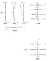
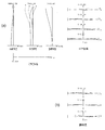
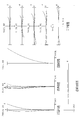
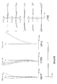
- FIG. 2A is a diagram showing various aberrations when the zoom lens according to Example 1 is in focus at infinity in the wide-angle end state
- FIG. 2B is a lateral aberration diagram when image blur correction is performed
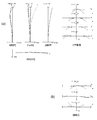
- FIG. 3A is a diagram of various aberrations at the time of focusing on infinity in the telephoto end state of the zoom lens according to Example 1
- FIG. 3B is a lateral aberration diagram when image blur correction is performed.
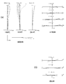
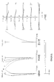
- FIG. 5A is a diagram illustrating various aberrations when the zoom lens according to Example 2 is in focus at infinity in the wide-angle end state
- FIG. 5B is a lateral aberration diagram when image blur correction is performed
- FIG. 6A is a diagram illustrating various aberrations when the zoom lens according to Example 2 is in focus at infinity in the telephoto end state
- FIG. 6B is a lateral aberration diagram when image blur correction is performed. It is a figure which shows the structure of a lens system and zoom locus
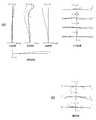
- FIG. 8A is a diagram of various aberrations at the time of focusing on infinity in the wide-angle end state of the zoom lens according to Example 3, and FIG.
- FIG. 8B is a lateral aberration diagram when image blur correction is performed.
- FIG. 9A is a diagram of various aberrations during focusing on infinity in the telephoto end state of the zoom lens according to Example 3
- FIG. 9B is a lateral aberration diagram when image blur correction is performed. It is a figure which shows the structure of a lens system and zoom locus
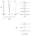
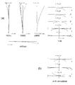
- FIGS. 11A and 11B are diagrams illustrating various aberrations at the time of focusing at infinity in the wide-angle end state of the zoom lens according to Example 4 and blur correction for 0.58 ° rotational shake. It is a meridional transverse aberration diagram at the time.
- FIG. 11A is a diagram of various aberrations during focusing on infinity in the telephoto end state of the zoom lens according to Example 3
- FIG. 9B is a lateral aberration diagram when image blur correction is performed. It is a figure which shows the structure of a lens system and zoom locus
- FIGS. 10 is a diagram illustrating various aberrations when the zoom lens according to Example 4 is in focus at infinity in the intermediate focal length state.
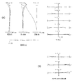
- FIGS. 13A and 13B are graphs showing various aberrations at the time of focusing on infinity in the telephoto end state of the zoom lens according to the fourth example, when shake correction is performed for a rotational shake of 0.18 °. It is a meridional transverse aberration diagram. It is a figure which shows the structure of a lens system and zoom locus
- FIGS. 15A and 15B are diagrams illustrating various aberrations at the time of focusing on infinity in the wide-angle end state of the zoom lens according to Example 5 and blur correction with respect to a rotational shake of 0.58 °.
- FIG. 12 is a diagram illustrating various aberrations when the zoom lens according to Example 5 is focused at infinity in the intermediate focal length state.
- FIGS. 17A and 17B are graphs showing various aberrations at the time of focusing on infinity in the telephoto end state of the zoom lens according to Example 5, and performing shake correction for rotational shake of 0.18 °.
- FIGS. 19A and 19B are diagrams illustrating various aberrations at the time of focusing on infinity in the wide-angle end state of the zoom lens according to Example 6 and blur correction with respect to a rotational shake of 0.58 °. It is a meridional transverse aberration diagram at the time.
- FIG. 12 is a diagram illustrating various aberrations when the zoom lens according to Example 6 was focused at infinity in the intermediate focal length state.
- FIGS. 21A and 21B are graphs showing various aberrations at the time of focusing on infinity in the telephoto end state of the zoom lens according to Example 6, and blur correction was performed for rotational shake of 0.18 °. It is a meridional transverse aberration diagram at the time.
- FIGS. 23A and 23B are graphs showing various aberrations at the time of focusing on infinity in the wide-angle end state of the zoom lens according to Example 7 and blur correction for 0.58 ° rotational shake. It is a meridional transverse aberration diagram at the time.
- FIG. 10 is a diagram illustrating various aberrations when the zoom lens according to Example 7 is in focus at infinity in the intermediate focal length state.
- FIGS. 25A and 25B are graphs showing various aberrations at the time of focusing on infinity in the telephoto end state of the zoom lens according to the seventh example, when shake correction is performed for a rotational shake of 0.18 °.
- FIGS. 27A and 27B are graphs showing various aberrations at the time of focusing on infinity in the wide-angle end state of the zoom lens according to Example 8 and blur correction for 0.58 ° rotational shake. It is a meridional transverse aberration diagram at the time.
- FIG. 10 is a diagram illustrating various aberrations when the zoom lens according to Example 8 is in focus at infinity in the intermediate focal length state.
- 29A and 29B are graphs showing various aberrations at the time of focusing on infinity in the telephoto end state of the zoom lens according to Example 8, in which shake correction was performed for rotational shake of 0.18 °. It is a meridional transverse aberration diagram at the time. It is a figure which shows the structure of a lens system and zoom locus
- FIGS. 31A and 31B are graphs showing various aberrations at the time of focusing on infinity in the wide-angle end state of the zoom lens according to Example 9 and blur correction with respect to a rotational shake of 0.58 °. It is a meridional transverse aberration diagram at the time.
- FIG 12A is a diagram illustrating various aberrations during focusing on infinity in the intermediate focal length state of the zoom lens according to Example 9;
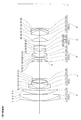
- FIGS. 33A and 33B are graphs showing various aberrations at the time of focusing on infinity in the telephoto end state of the zoom lens according to Example 9, and blur correction was performed for rotational shake of 0.18 °. It is a meridional transverse aberration diagram at the time. It is a schematic sectional view of a digital single-lens reflex camera CAM (optical apparatus) provided with the zoom lens having the above-described configuration as a photographing lens.
- CAM optical apparatus
- the zoom lens according to the first embodiment includes a first lens group G1 having a positive refractive power and a second lens group G2 having a negative refractive power, which are arranged in order from the object side, for example, as shown in FIG.
- Image plane correction at the time of occurrence of camera shake is performed by moving at least a part of the lens groups so as to have a component orthogonal to the optical axis.
- the fourth lens group G4 has a smaller number of constituent lenses than the other lens groups, and the lens diameter can be reduced, so that it is suitable for incorporating a camera shake correction mechanism. With this configuration, it is possible to reduce the size of the lens barrel, and it is possible to satisfactorily correct aberration fluctuations accompanying camera shake correction.
- Conditional expression (1) defines the focal length f5 of the fifth lens group G5 with respect to the focal length ft in the telephoto end state.
- the present zoom lens can reduce the burden on aberrations and zooming to other lens groups other than the fifth lens group G5, thus realizing good optical performance.
- a predetermined zoom ratio can be ensured. If the upper limit of conditional expression (1) is exceeded, the refractive power of the fifth lens group G5 becomes too weak, and the refractive power of the other lens groups becomes strong in order to ensure the zoom ratio, and the spherical surface in the telephoto end state. It becomes difficult to correct aberrations. On the other hand, if the lower limit of conditional expression (1) is not reached, the refractive power of the fifth lens group G5 becomes too strong, making it difficult to correct coma in the wide-angle end state.
- the upper limit of conditional expression (1) it is preferable to set the upper limit of conditional expression (1) to 0.24. Accordingly, the focal length of the fifth lens group G5 can be more appropriately arranged, and spherical aberration in the telephoto end state can be corrected more favorably. In order to secure the effect of the present embodiment, it is preferable to set the lower limit of conditional expression (1) to 0.05. Thereby, the focal length of the fifth lens group G5 can be more appropriately arranged, and coma aberration in the wide-angle end state can be corrected more favorably.
- the condition of the following expression (2) is satisfied when the focal length of the second lens group G2 is f2 and the focal length of the fourth lens group G4 is f4.
- the conditional expression (2) defines the focal length f2 of the second lens group G2 with respect to the focal length f4 of the fourth lens group G4.
- the present zoom lens can satisfy the conditional expression (2), thereby realizing good optical performance and ensuring a predetermined zoom ratio. If the upper limit value of conditional expression (2) is exceeded, the refractive power of the second lens group G2 becomes too weak, and it becomes difficult to ensure the amount of peripheral light in the wide-angle end state. If the refractive powers of the other lens groups are increased to alleviate this influence, it becomes difficult to correct spherical aberration in the telephoto end state. On the other hand, if the lower limit of conditional expression (2) is not reached, the refractive power of the second lens group G2 becomes too strong, and the field curvature and astigmatism in the wide-angle end state deteriorate.
- the upper limit of conditional expression (2) it is preferable to set the upper limit of conditional expression (2) to 1.000. Accordingly, the focal lengths of the second lens group G2 and the fourth lens group G4 can be more appropriately arranged, and spherical aberration in the telephoto end state can be corrected more favorably. In order to secure the effect of the present embodiment, it is preferable to set the lower limit of conditional expression (2) to 0.580. Thereby, the focal lengths of the second lens group G2 and the fourth lens group G4 can be more appropriately arranged, and field curvature and astigmatism in the wide-angle end state can be corrected more favorably.
- conditional expression (2) it is preferable to set the upper limit value of conditional expression (2) to 0.900. In order to further secure the effect of the present embodiment, it is more preferable to set the lower limit value of conditional expression (2) to 0.590.
- the focal length of the fourth lens group G4 is f4 and the focal length is ft in the telephoto end state when the entire lens system is focused at infinity
- the condition of the following expression (3) is satisfied. It is preferable to do.
- Conditional expression (3) defines the focal length f4 of the fourth lens group G4 with respect to the focal length ft in the telephoto end state.
- this zoom lens can realize good optical performance and ensure a predetermined zoom ratio. If the upper limit value of conditional expression (3) is exceeded, the refractive power of the fourth lens group G4 becomes too weak, and the shift amount of the fourth lens group G4 increases in order to correct camera shake. In addition, it is difficult to correct astigmatism fluctuations during camera shake correction. On the other hand, if the lower limit of conditional expression (3) is not reached, the refractive power of the fourth lens group G4 becomes strong, and it becomes difficult to correct spherical aberration in the telephoto end state.
- the focal length of the fourth lens group G4 can be more appropriately arranged, and fluctuations in astigmatism during camera shake correction can be suppressed more favorably.
- the fourth lens group G4 includes the lens group GA having a negative refractive power and the lens group GB that is disposed adjacent to the image side of the lens group GA and has a negative refractive power. It is preferable to have. Furthermore, it is preferable that the lens group GB includes at least one aspheric surface. As a result, it is possible to simultaneously correct the fluctuation of the curvature of field at the time of camera shake correction in the telephoto end state and the fluctuation of the eccentric coma aberration.
- the focal length of the lens group which is a vibration-proof lens group that moves so as to have a component orthogonal to the optical axis, is fA, and the telephoto end state when the entire lens system is focused at infinity
- the focal length at is ft, it is preferable to satisfy the condition of the following expression (4).
- the conditional expression (4) defines the focal length fA of the lens unit that is the anti-vibration lens unit with respect to the focal length ft in the telephoto end state.
- the focal length fA of the lens group that is the anti-vibration lens group can be more appropriately arranged, and spherical aberration in the telephoto end state can be corrected more favorably.
- the focal length fA of the lens group that is the anti-vibration lens group can be arranged more appropriately, and astigmatism fluctuations during camera shake correction can be corrected better.
- conditional expression (4) it is preferable to set the lower limit value of conditional expression (4) to 0.10. In order to further secure the effect of the present embodiment, it is preferable to set the upper limit of conditional expression (4) to 0.25.
- the condition of the following expression (5) is satisfied when the focal length of the fourth lens group G4 is f4 and the focal length of the fifth lens group G5 is f5.
- the conditional expression (5) defines the focal length f5 of the fifth lens group G5 with respect to the focal length f4 of the fourth lens group G4.
- the zoom lens satisfies the conditional expression (5), thereby realizing good optical performance and ensuring a predetermined zoom ratio. If the upper limit value of conditional expression (5) is exceeded, the refractive power of the fourth lens group G4 becomes too strong, the decentering coma during camera shake correction increases, and the field curvature fluctuations also increase. On the other hand, if the lower limit of conditional expression (5) is not reached, the refractive power of the fifth lens group G5 becomes too strong, and coma, curvature of field, and distortion become large.
- the focal length f4 of the fourth lens group G4 and the focal length f5 of the fifth lens group G5 can be more appropriately arranged, the decentering coma aberration during camera shake correction can be further reduced, and the image plane The bending fluctuation can be further reduced.
- the focal length of the fifth lens group G5 is f5 and the focal length at the wide-angle end state when the entire lens system is focused at infinity is fw, the condition of the following equation (6) is satisfied. It is preferable to satisfy.
- the conditional expression (6) defines the focal length f5 of the fifth lens group G5 with respect to the focal length fw in the wide-angle end state of the entire lens system.
- the zoom lens can satisfy the conditional expression (6), thereby realizing good optical performance and ensuring a predetermined zoom ratio. If the upper limit of conditional expression (6) is exceeded, the refractive power of the fifth lens group G5 becomes too weak, and the refractive power of the other lens groups becomes strong to secure the zoom ratio, and the spherical surface in the telephoto end state. It becomes difficult to correct aberrations. On the other hand, if the lower limit of conditional expression (6) is not reached, the refractive power of the fifth lens group G5 becomes too strong, making it difficult to correct coma in the wide-angle end state.
- the focal length f5 of the fifth lens group G5 can be more appropriately arranged with respect to the focal length fw of the wide-angle end state of the entire lens system, and spherical aberration in the telephoto end state can be corrected more favorably. it can.
- the focal length f5 of the fifth lens group G5 can be more appropriately arranged with respect to the focal length fw of the wide-angle end state of the entire lens system, and coma aberration in the wide-angle end state can be corrected more favorably. it can.
- the fourth lens group G4 has a cemented lens. With this configuration, both axial chromatic aberration and lateral chromatic aberration can be corrected well.
- the distance between the first lens group G1 and the second lens G2 increases, and the second lens group G2 and the third lens group G3
- the distance between the third lens group G3 and the fourth lens group G4 increases, and the distance between the fourth lens group G4 and the fifth lens group G5 decreases.
- the third lens group G3 and the fifth lens group G5 move together when zooming from the wide-angle end state to the telephoto end state.
- the eccentricity of the fifth lens group G5 it is possible to reduce the deterioration in performance due to the eccentricity of the fifth lens group G5 at the time of manufacture while ensuring a predetermined zoom ratio.
- the third lens group G3 preferably includes three lens groups having a positive refractive power, and these three lens groups preferably include at least two cemented lenses. Thereby, the field curvature in the wide-angle end state and the spherical aberration in the telephoto end state can be corrected simultaneously.
- focusing from an infinitely distant object to a close object is performed by moving at least a part of the second lens group G2 in the optical axis direction.
- fluctuations in spherical aberration, curvature of field, and the like during focusing on a short-distance object can be reduced.
- the small lens group as the focusing lens group, it is possible to focus quickly.
- the zoom lens according to the second embodiment includes a first lens group G1 having positive refractive power and a second lens group G2 having negative refractive power, which are arranged in order from the object side.
- Image plane correction at the time of occurrence of camera shake is performed by moving at least a part of the lens groups so as to have a component orthogonal to the optical axis.
- the fourth lens group G4 has a smaller number of constituent lenses than the other lens groups, and the lens diameter can be reduced, so that it is suitable for incorporating a camera shake correction mechanism. With this configuration, it is possible to reduce the size of the lens barrel, and it is possible to satisfactorily correct aberration fluctuations accompanying camera shake correction.
- the conditional expression (7) defines the focal length ft in the telephoto end state with respect to the focal length f4 of the fourth lens group G4.
- the present zoom lens can achieve good optical performance by satisfying the conditional expression (7), and can ensure a predetermined zoom ratio. If the lower limit of conditional expression (7) is not reached, the refractive power of the fourth lens group G4 becomes strong, and it becomes difficult to correct spherical aberration in the telephoto end state. On the other hand, if the upper limit value of conditional expression (7) is exceeded, the refractive power of the fourth lens group G4 becomes weak, the shift amount of the fourth lens group G4 increases, and the fluctuation of astigmatism during camera shake correction is corrected. It becomes difficult.
- the condition of the following expression (8) is satisfied when the focal length of the fifth lens group G5 is f5 and the focal length of the fourth lens group G4 is f4.
- the conditional expression (8) defines the focal length f4 of the fourth lens group G4 with respect to the focal length f5 of the fifth lens group G5. This zoom lens satisfies the conditional expression (8), thereby realizing good optical performance and ensuring a predetermined zoom ratio. If the upper limit of conditional expression (8) is exceeded, the refractive power of the fourth lens group G4 becomes strong, and it becomes difficult to correct spherical aberration in the telephoto end state. On the other hand, if the lower limit of conditional expression (8) is not reached, the refractive power of the fifth lens group G5 becomes strong, and it becomes difficult to correct coma in the wide-angle end state.
- the condition of the following expression (9) is satisfied when the focal length of the second lens group G2 is f2, and the focal length f4 of the fourth lens group G4.
- conditional expression (9) defines the focal length f4 of the fourth lens group G4 with respect to the focal length f2 of the second lens group G2.
- This zoom lens can realize good optical performance by satisfying conditional expression (9). If the upper limit value of conditional expression (9) is exceeded, the refractive power of the fourth lens group G4 becomes strong, and it is possible to simultaneously correct the fluctuations in field curvature and the decentration coma aberration during camera shake correction. It becomes difficult. On the other hand, if the lower limit value of conditional expression (9) is not reached, the refractive power of the second lens group G2 becomes strong, and it becomes difficult to correct off-axis aberrations, particularly field curvature and astigmatism, in the wide-angle end state.
- the condition of the following expression (10) is satisfied when the focal length of the first lens group G1 is f1 and the focal length of the fourth lens group G4 is f4.
- the conditional expression (10) defines the focal length f4 of the fourth lens group G4 with respect to the focal length f1 of the first lens group G1.
- the zoom lens satisfies the conditional expression (10), so that a predetermined zoom ratio can be ensured while ensuring optical performance during camera shake correction. If the upper limit value of conditional expression (10) is exceeded, the refractive power of the fourth lens group G4 becomes strong, and it is possible to simultaneously correct the fluctuations in the curvature of field and the decentration coma aberration during camera shake correction. It becomes difficult. On the other hand, if the lower limit of conditional expression (10) is not reached, the refractive power of the first lens group G1 becomes strong, and it becomes difficult to correct spherical aberration in the telephoto end state. Further, the deterioration of lateral chromatic aberration in the wide-angle end state becomes significant, which is not preferable.
- the fourth lens group G4 includes a lens group GA having a negative refractive power and a lens group GB having a negative refractive power, which are arranged in order from the object side. Furthermore, it is preferable that the lens group GB (arranged adjacent to the image side of the lens group GA) has at least one aspheric surface. As a result, it is possible to simultaneously correct the fluctuation of the curvature of field at the time of camera shake correction in the telephoto end state and the fluctuation of the eccentric coma.
- the fourth lens group G4 has a cemented lens. With this configuration, both axial chromatic aberration and lateral chromatic aberration can be corrected well.
- the distance between the first lens group G1 and the second lens group G2 increases, and the second lens group G2 and the third lens group G3
- the distance between the third lens group G3 and the fourth lens group G4 increases, and the distance between the fourth lens group G4 and the fifth lens group G5 decreases.
- the third lens group G3 and the fifth lens group G5 move together when zooming from the wide-angle end state to the telephoto end state.
- the eccentricity of the fifth lens group G5 it is possible to reduce the deterioration in performance due to the eccentricity of the fifth lens group G5 at the time of manufacture while ensuring a predetermined zoom ratio.
- f5 is the focal length of the fifth lens group G5 and ft is the focal length of the entire lens system in the telephoto end state.
- the conditional expression (11) defines the focal length ft in the telephoto end state with respect to the focal length f5 of the fifth lens group G5.
- the zoom lens can satisfy the conditional expression (11) to achieve good optical performance and ensure a predetermined zoom ratio. If the upper limit value of the conditional expression (11) is exceeded, the refractive power of the fifth lens group G5 becomes weak, the refractive power of the third lens group G3 becomes strong in order to secure the zoom ratio, and in the telephoto end state. Correction of spherical aberration becomes difficult. On the other hand, if the lower limit value of conditional expression (11) is not reached, the refractive power of the fifth lens group G5 becomes strong, and it becomes difficult to correct coma in the wide-angle end state.
- the fifth lens group G5 includes at least two lens groups having a positive refractive power and a lens group having a negative refractive power.
- the fifth lens group G5 preferably includes at least one cemented lens.
- the conditional expression (12) defines the focal length f3 of the third lens group G3 with respect to the difference between the back focus Bft in the telephoto end state and the back focus Bfw in the wide angle end state.
- the zoom lens can satisfy the conditional expression (12) to achieve good optical performance and ensure a predetermined zoom ratio. If the upper limit of conditional expression (12) is exceeded, the refractive power of the third lens group G3 becomes strong, and it becomes difficult to correct spherical aberration in the telephoto end state.
- conditional expression (12) On the other hand, if the lower limit value of conditional expression (12) is not reached, the refractive powers of the first lens group G1 and the second lens group G2 become stronger, and correction of higher-order coma aberration fluctuations that occur from the wide-angle end state to the telephoto end state is corrected. It becomes difficult.
- the third lens group G3 includes at least three lens groups having positive refractive power. More preferably, the third lens group G3 preferably includes at least one cemented lens. Thereby, the field curvature in the wide-angle end state and the spherical aberration in the telephoto end state can be corrected simultaneously.
- the second lens group G2 has at least one aspheric surface. Thereby, it is possible to satisfactorily correct field curvature and distortion in the wide-angle end state.
- the zoom lens according to the third embodiment includes, for example, a first lens group G1 having a positive refractive power and a second lens group G2 having a negative refractive power, which are arranged in order from the object side, as shown in FIG.
- Image plane correction at the time of occurrence of camera shake is performed by moving some lens groups so as to have a component in a direction orthogonal to the optical axis.
- the fourth lens group G4 is suitable for incorporating a camera shake correction mechanism because the number of constituent lenses is smaller than that of the other lens groups and the lens diameter can be reduced. Accordingly, it is possible to reduce the size of the lens barrel, and it is possible to satisfactorily correct aberration fluctuations accompanying camera shake correction.
- the conditional expression (13) defines the focal length f4 of the fourth lens group G4 with respect to the focal length f1 of the first lens group G1.
- the zoom lens satisfies the conditional expression (13), so that a predetermined zoom ratio can be ensured while ensuring optical performance during camera shake correction. If the upper limit value of conditional expression (13) is exceeded, the refractive power of the fourth lens group G4 becomes strong, and it is possible to simultaneously correct the fluctuations in the curvature of field and the decentration coma aberration during camera shake correction. It becomes difficult.
- conditional expression (13) if the lower limit value of conditional expression (13) is not reached, the refractive power of the first lens group G1 becomes strong, and it becomes difficult to correct spherical aberration in the telephoto end state. Further, the deterioration of lateral chromatic aberration in the wide-angle end state becomes significant, which is not preferable.
- the condition of the following expression (14) is satisfied when the focal length of the fourth lens group G4 is f4 and the focal length is ft in the telephoto end state of the entire lens system.
- the conditional expression (14) defines the focal length f4 of the fourth lens group G4 with respect to the focal length ft in the telephoto end state.
- This zoom lens can satisfy the conditional expression (14) to realize good optical performance and to ensure a predetermined zoom ratio. If the upper limit value of conditional expression (14) is exceeded, the refractive power of the fourth lens group G4 becomes weak, the shift amount of the fourth lens group G4 increases, and astigmatism fluctuations during camera shake correction are corrected. It becomes difficult. On the other hand, if the lower limit value of conditional expression (14) is not reached, the refractive power of the fourth lens group G4 becomes strong, and it becomes difficult to correct spherical aberration in the telephoto end state.
- the distance between the first lens group G1 and the second lens group G2 increases, and the second lens group G2 and the third lens group G3
- the distance between the third lens group G3 and the fourth lens group G4 increases, and the distance between the fourth lens group G4 and the fifth lens group G5 decreases.
- the fourth lens group G4 includes the lens group GA having negative refractive power and the lens group GB having negative refractive power, which are arranged in order from the object side. As a result, it is possible to simultaneously correct the variation in curvature of field at the time of camera shake correction in the telephoto end state and the variation in eccentric coma.
- the fourth lens group G4 has at least one aspheric surface. As a result, it is possible to simultaneously correct the variation in curvature of field at the time of camera shake correction in the telephoto end state and the variation in eccentric coma.
- the fourth lens group G4 has a cemented lens. With this configuration, axial and lateral chromatic aberration can be corrected well.
- the condition of the following expression (15) is satisfied when the focal length of the second lens group G2 is f2 and the focal length f4 of the fourth lens group G4.
- conditional expression (15) defines the focal length f4 of the fourth lens group G4 with respect to the focal length f2 of the second lens group G2.
- This zoom lens can achieve good optical performance by satisfying conditional expression (15). If the upper limit value of the conditional expression (15) is exceeded, the refractive power of the fourth lens group G4 becomes strong, and it is possible to simultaneously correct the fluctuation of the curvature of field and the fluctuation of the decentration coma aberration when the camera shake is corrected. It becomes difficult. On the other hand, if the lower limit value of conditional expression (15) is not reached, the refractive power of the second lens group G2 becomes strong, and it becomes difficult to correct off-axis aberrations, particularly field curvature and astigmatism, in the wide-angle end state.
- the back focus in the telephoto end state is Bft
- the back focus in the wide-angle end state is Bfw
- the focal length of the third lens group G3 is f3
- the condition of the following expression (16) is satisfied. It is preferable to do.
- the conditional expression (16) defines the focal length f3 of the third lens group G3 with respect to the difference between the back focus Bft in the telephoto end state and the back focus Bfw in the wide angle end state.
- the zoom lens can satisfy the conditional expression (16) to realize good optical performance and to secure a predetermined zoom ratio. If the upper limit of conditional expression (16) is exceeded, the refractive power of the third lens group G3 becomes strong, and it becomes difficult to correct spherical aberration in the telephoto end state.
- conditional expression (16) if the lower limit value of conditional expression (16) is not reached, the refractive powers of the first lens group G1 and the second lens group G2 become stronger, and correction of higher-order coma aberration variation that occurs from the wide-angle end state to the telephoto end state is corrected. It becomes difficult.
- f5 is the focal length of the fifth lens group G5 and ft is the focal length of the entire lens system in the telephoto end state.
- the conditional expression (17) defines the focal length ft in the telephoto end state with respect to the focal length f5 of the fifth lens group G5.
- This zoom lens can satisfy the conditional expression (17) to realize good optical performance and to secure a predetermined zoom ratio. If the upper limit of conditional expression (17) is exceeded, the refractive power of the fifth lens group G5 becomes weak, and the refractive power of the third lens group G3 becomes strong in order to secure the zoom ratio, so that in the telephoto end state. Correction of spherical aberration becomes difficult. On the other hand, if the lower limit value of conditional expression (17) is not reached, the refractive power of the fifth lens group G5 becomes strong, and it becomes difficult to correct coma in the wide-angle end state.
- the focal length of the first lens group G1 is f1
- the focal length f3 of the third lens group G3 it is preferable that the condition of the following formula (18) is satisfied.
- the conditional expression (18) defines the focal length f3 of the third lens group G3 with respect to the focal length f1 of the first lens group G1.
- the present zoom lens can achieve good optical performance by satisfying conditional expression (18), and can also perform color correction more effectively. If the upper limit of conditional expression (18) is exceeded, the refractive power of the third lens group G3 becomes strong, and it becomes difficult to correct coma aberration in the wide-angle end state and spherical aberration in the telephoto end state. Further, the deterioration of the imaging performance due to a manufacturing error becomes remarkable. On the other hand, if the lower limit of conditional expression (18) is not reached, the refractive power of the first lens group G1 will become strong, and it will be difficult to correct lateral chromatic aberration.
- the third lens group G3 and the fifth lens group G5 move together when zooming from the wide-angle end state to the telephoto end state.
- the eccentricity of the fifth lens group G5 it is possible to reduce the deterioration in performance due to the eccentricity of the fifth lens group G5 at the time of manufacture while ensuring a predetermined zoom ratio.
- the second lens group G2 has an aspherical surface. Thereby, it is possible to satisfactorily correct field curvature and distortion in the wide-angle end state.
- the third lens group G3 includes at least three positive lenses. Therefore, the field curvature in the wide-angle end state and the spherical aberration in the telephoto end state can be corrected simultaneously.
- FIG. 34 is a schematic sectional view of a digital single-lens reflex camera CAM (optical apparatus) provided with the zoom lens having the above-described configuration as the photographing lens 1.
- a digital single-lens reflex camera CAM optical apparatus
- FIG. 34 shows that light from an object (subject) (not shown) is collected by the photographing lens 1 and imaged on the focusing screen 4 via the quick return mirror 3.
- the light imaged on the focusing screen 4 is reflected a plurality of times in the pentaprism 5 and guided to the eyepiece lens 6.
- the photographer can observe the object (subject) image as an erect image through the eyepiece 6.
- the camera CAM shown in FIG. 34 may be one that holds the photographing lens 1 in a detachable manner or may be molded integrally with the photographing lens 1.
- the camera CAM may be a so-called single-lens reflex camera or a compact camera that does not have a quick return mirror or the like.
- Tables 1 to 9 are shown below. These are tables of specifications in the first to ninth examples.
- f represents the focal length of the entire lens system
- FNO represents the F number
- ⁇ represents the half field angle
- Y represents the image height
- TL represents the total length of the lens system
- Bf represents the back focus.
- the surface number is the order of the lens surfaces from the object side along the direction in which the light beam travels
- r is the radius of curvature of each lens surface
- d is the next optical surface (or image from each optical surface).
- ⁇ d represents the Abbe number with respect to the d-line (wavelength 587.6 nm)
- nd represents the refractive index with respect to the d-line.
- f is the focal length of the entire lens system
- ⁇ is the imaging magnification between the object and the image
- Di (where i is an integer) is the i-th surface.
- Bf indicates a back focus with a variable surface interval.
- 1-POS is focused at infinity in the wide-angle end state
- 2-POS is focused at infinity in the first intermediate focal length state
- 3-POS is focused at infinity in the second intermediate focal length state.
- 4-POS is in focus at infinity in the telephoto end state
- 6-POS is in the first intermediate focal length state.
- f indicates the focal length of the entire lens system
- Di indicates the variable surface interval of the i-th surface.
- mm is generally used as the focal length f, radius of curvature r, surface interval d, and other length units.
- the unit is not limited to “mm”, and other appropriate units can be used.
- first to ninth examples will be described.
- the first to third examples correspond to the first embodiment
- the fourth to sixth examples correspond to the second embodiment.
- the seventh to ninth examples correspond to the third embodiment.
- the lens groups constituting the zoom lens in each embodiment are expressed in order from the object side as the first lens group G1, the second lens group G2,..., And the lenses constituting each lens group are the first lens group.
- L11, L12,... In the second lens group and denoted by L21, L22,...
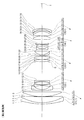
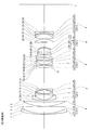
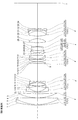
- FIG. 1 shows a lens configuration diagram and zoom locus of the first embodiment.
- the zoom lens according to the first example includes a first lens group G1 having a positive refractive power and a second lens having a negative refractive power, which are arranged in order from the object side along the optical axis. It has a lens group G2, a third lens group G3 having a positive refractive power, a fourth lens group G4 having a negative refractive power, and a fifth lens group G5 having a positive refractive power.
- the first lens group G1 includes, in order from the object side, a cemented positive lens including a negative meniscus lens L11 having a convex surface facing the object side and a biconvex lens L12, and a positive meniscus lens L13 having a convex surface facing the object side.
- a cemented positive lens including a negative meniscus lens L11 having a convex surface facing the object side and a biconvex lens L12, and a positive meniscus lens L13 having a convex surface facing the object side.
- the second lens group G2 includes, in order from the object side, a negative meniscus lens L21 having an aspheric surface with a convex surface facing the object side, a biconcave lens L22, a biconvex lens L23, and a negative meniscus lens with a concave surface facing the object side. And a negative positive meniscus lens L25 having a concave surface facing the object side.
- the negative meniscus lens L21 is a so-called composite aspheric lens having both a portion made of a resin material having an aspheric surface and a portion made of a glass material.
- the third lens group G3 includes a biconvex lens L31 arranged in order from the object side, a positive meniscus lens L32 having a convex surface facing the object side, a negative meniscus lens L33 having a convex surface facing the object side, and a convex surface facing the object side. And a positive cemented lens composed of a positive meniscus lens L34.
- the fourth lens group G4 includes, in order from the object side, a lens group GA having a negative refractive power for performing camera shake correction by moving the lens group so as to have a component substantially orthogonal to the optical axis, and a negative refractive power.
- the lens group GA includes a cemented negative lens that is arranged in order from the object side and includes a biconcave lens L41 and an aspheric positive lens L42 having an aspheric surface on the image side and a convex surface facing the object side.
- the lens group GB includes a negative meniscus lens L43 having a concave surface facing the object side.
- the fifth lens group G5 is composed of an aspherical biconvex lens L51 having an aspheric surface on the image side and a cemented positive lens that is composed of a biconvex lens L52 and a negative meniscus lens L53 having a concave surface on the object side. And a negative meniscus lens L54 having a concave surface facing the object side.
- the zoom lens according to the present embodiment having such a configuration, when zooming from the wide-angle end state to the telephoto end state, the distance between the first lens group G1 and the second lens group increases, and the second lens group G2 And the third lens group G3 are decreased, the distance between the third lens group G3 and the fourth lens group G4 is increased, and the distance between the fourth lens group G4 and the fifth lens group G5 is decreased. At this time, the third lens group G3 and the fifth lens group G5 move together.
- focusing on an object at a short distance from infinity is performed by extending in the object direction of the second lens group G2.
- the aperture stop S is disposed between the second lens group G2 and the third lens group G3, and moves together with the third lens group G3 upon zooming from the wide-angle end state to the telephoto end state.
- Table 1 below lists the values of each specification of the zoom lens according to the first example.
- the surface numbers 1 to 35 in Table 1 correspond to the surfaces 1 to 35 shown in FIG.
- FNO represents an F number
- Y represents an image height (unit: mm).
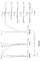
- the spherical aberration diagram shows the F-number value corresponding to the maximum aperture
- the astigmatism diagram and the distortion diagram show the maximum image height
- the coma diagram shows the value of each image height.
- d indicates various aberrations with respect to the d-line (wavelength 587.6 nm)
- g indicates various aberrations with respect to the g-line (wavelength 435.8 nm)
- those not described indicate various aberrations with respect to the d-line.
- the solid line indicates the sagittal image plane
- the broken line indicates the meridional image plane.
- FIG. 4 shows a lens configuration diagram and zoom locus of the second embodiment.
- the zoom lens according to the second example includes a first lens group G1 having a positive refractive power and a second lens having a negative refractive power, which are arranged in order from the object side along the optical axis. It has a lens group G2, a third lens group G3 having a positive refractive power, a fourth lens group G4 having a negative refractive power, and a fifth lens group G5 having a positive refractive power.
- the first lens group G1 includes, in order from the object side, a cemented positive lens including a negative meniscus lens L11 having a convex surface facing the object side and a positive meniscus lens L12 having a convex surface facing the object side, and a convex surface facing the object side. And a positive meniscus lens L13.
- the second lens group G2 includes an aspheric negative meniscus lens L21 having a convex surface facing the object side and an aspheric surface on the object side, a biconcave lens L22, a biconvex lens L23, and an object side. And a plano-concave lens L24 having a concave surface.
- the third lens group G3 includes, in order from the object side, a biconvex lens L31, a cemented positive lens including the biconvex lens L32 and a negative meniscus lens L33 having a concave surface facing the object side, and a negative lens having a convex surface facing the object side. It has a cemented positive lens composed of a meniscus lens L34 and a biconvex lens L35.
- the fourth lens group G4 has a negative refractive power, a lens group GA having negative refractive power, which is arranged in order from the object side, and performs camera shake correction by moving so as to have a component substantially orthogonal to the optical axis.
- a lens group GB has a cemented negative lens composed of a biconcave lens L41 and a positive meniscus lens having a convex surface facing the object side, which are arranged in order from the object side.
- the lens group GB includes a negative meniscus lens L43 having a concave surface facing the image side.
- the negative meniscus lens L43 is a so-called composite aspheric lens having both a portion made of a resin material having an aspheric surface and a portion made of a glass material.
- the fifth lens group G5 is composed of an aspherical biconvex lens L51 having an aspheric surface on the image side and a cemented positive lens that is composed of a biconvex lens L52 and a negative meniscus lens L53 having a concave surface on the object side. And a negative meniscus lens L54 having a concave surface facing the object side.
- the zoom lens according to the present embodiment having such a configuration, when zooming from the wide-angle end state to the telephoto end state, the distance between the first lens group G1 and the second lens group increases, and the second lens group G2 And the third lens group G3 are decreased, the distance between the third lens group G3 and the fourth lens group G4 is increased, and the distance between the fourth lens group G4 and the fifth lens group G5 is decreased. At this time, the third lens group G3 and the fifth lens group G5 move together.
- focusing on an object at a short distance from infinity is performed by extending in the object direction of the second lens group G2.
- the aperture stop S is disposed between the second lens group G2 and the third lens group G3, and moves together with the third lens group G3 upon zooming from the wide-angle end state to the telephoto end state.
- Table 2 below lists the values of various specifications of the zoom lens according to the second example.
- the surface numbers 1 to 35 in Table 2 correspond to the surfaces 1 to 35 shown in FIG.
- FIG. 7 shows a lens configuration diagram and zoom locus of the third embodiment.
- the zoom lens according to the third example includes a first lens group G1 having a positive refractive power and a second lens having a negative refractive power, which are arranged in order from the object side along the optical axis. It has a lens group G2, a third lens group G3 having a positive refractive power, a fourth lens group G4 having a negative refractive power, and a fifth lens group G5 having a positive refractive power.
- the first lens group G1 includes, in order from the object side, a cemented positive lens including a negative meniscus lens L11 having a convex surface facing the object side and a positive meniscus lens L12 having a convex surface facing the object side, and a convex surface facing the object side. And a positive meniscus lens L13.
- the second lens group G2 includes an aspheric negative meniscus lens L21 having a convex surface facing the object side and an aspheric surface on the object side, a biconcave lens L22, a biconvex lens L23, and an object side. And a plano-concave lens L24 having a concave surface.
- the third lens group G3 includes, in order from the object side, a biconvex lens L31, a cemented positive lens including the biconvex lens L32 and a negative meniscus lens L33 having a concave surface facing the object side, and a negative lens having a convex surface facing the object side. It has a cemented positive lens composed of a meniscus lens L34 and a biconvex lens L35.
- the fourth lens group G4 has a negative refractive power, a lens group GA having negative refractive power, which is arranged in order from the object side, and performs camera shake correction by moving so as to have a component substantially orthogonal to the optical axis.
- a lens group GB has a cemented negative lens composed of a biconcave lens L41 and a positive meniscus lens L42 having a convex surface facing the object side, which are arranged in order from the object side.
- the lens group GB includes a negative meniscus lens L43 having a concave surface facing the image side.
- the negative meniscus lens L43 is a so-called composite aspheric lens having both a portion made of a resin material having an aspheric surface and a portion made of a glass material.
- the fifth lens group G5 includes an aspherical biconvex lens L51 having an aspheric surface on the image side, a biconvex lens L52, and a negative meniscus lens L53 with a concave surface facing the object side, which are arranged in order from the object side.
- the zoom lens according to the present embodiment having such a configuration, when zooming from the wide-angle end state to the telephoto end state, the distance between the first lens group G1 and the second lens group increases, and the second lens group G2 And the third lens group G3 are decreased, the distance between the third lens group G3 and the fourth lens group G4 is increased, and the distance between the fourth lens group G4 and the fifth lens group G5 is decreased. At this time, the third lens group G3 and the fifth lens group G5 move together.
- focusing on an object at a short distance from infinity is performed by extending in the object direction of the second lens group G2.
- the aperture stop S is disposed between the second lens group G2 and the third lens group G3, and moves together with the third lens group G3 upon zooming from the wide-angle end state to the telephoto end state.
- Table 3 below lists the values of each specification of the zoom lens according to the third example.
- the surface numbers 1 to 34 in Table 3 correspond to the surfaces 1 to 34 shown in FIG.
- the five-group configuration is shown, but the present invention can be applied to other group configurations such as the sixth group and the seventh group. Further, a configuration in which a lens or a lens group is added to the most object side, or a configuration in which a lens or a lens group is added to the most image side may be used.
- the lens group refers to a portion having at least one lens separated by an air interval that changes during zooming.
- the focusing lens group may be a focusing lens group that performs focusing from an object at infinity to a near object by moving a single lens group, a plurality of lens groups, or a partial lens group in the optical axis direction.
- the focusing lens group can be applied to autofocus, and is also suitable for driving a motor for autofocus (such as an ultrasonic motor).
- a motor for autofocus such as an ultrasonic motor
- the lens group or the partial lens group is moved so as to have a component in a direction perpendicular to the optical axis, or is rotated (swayed) in the in-plane direction including the optical axis to reduce image blur caused by camera shake.
- a vibration-proof lens group to be corrected may be used.
- the movement may be rotational movement (swing) with a certain point on the optical axis as the rotation center.
- the lens surface may be formed of a spherical surface, a flat surface, or an aspheric surface.
- the lens surface is a spherical surface or a flat surface, lens processing and assembly adjustment are facilitated, and optical performance deterioration due to errors in processing and assembly adjustment can be prevented. In addition, even when the image plane is deviated, it is preferable because there is little deterioration in drawing performance.
- the aspherical surface is an aspherical surface formed by grinding, a glass mold aspherical surface formed of glass with an aspherical shape, or a composite aspherical surface formed of resin on the glass surface with an aspherical shape. Any aspherical surface may be used.
- the lens surface may be a diffractive surface, and the lens may be a gradient index lens (GRIN lens) or a plastic lens.
- GRIN lens gradient index lens
- the aperture stop S is preferably arranged in the vicinity of the third lens group G3 or the fourth lens group G4. However, the role of the aperture stop may be substituted by a lens frame without providing a member as an aperture stop. . In particular, the aperture stop S is more preferably on the object side of the third lens group G3.
- each lens surface may be provided with an antireflection film having high transmittance in a wide wavelength range in order to reduce flare and ghost and achieve high optical performance with high contrast.
- the zoom lens (variable magnification optical system) of the present embodiment has a magnification ratio of 5 to 18 times, more preferably 8 to 12 times.
- the first lens group G1 has two positive lenses and one negative lens. In the first lens group G1, it is preferable to dispose the lenses in order of negative / positive from the object side.
- the second lens group G2 has one positive lens and three negative lenses.
- lens components are arranged in order of negative, negative, positive and negative in order from the object side with an air gap interposed therebetween.
- the third lens group G3 has three positive lenses and one negative lens.
- lens components are arranged in order of positive and positive in order from the object side with an air gap interposed therebetween.
- the fourth lens group G4 has one positive lens and two negative lenses.
- the fourth lens group G4 it is preferable to dispose lens components in the order of negative and negative in order from the object side with an air gap interposed therebetween.
- the fifth lens group G5 has two positive lenses and one negative lens.
- lens components are arranged in order of positive and negative in order from the object side with an air gap interposed therebetween.
- FIG. 10 shows a lens configuration diagram and zoom locus of the fourth example.
- the zoom lens according to the fourth example includes a first lens group G1 having a positive refractive power and a second lens having a negative refractive power, which are arranged in order from the object side along the optical axis. It has a lens group G2, a third lens group G3 having a positive refractive power, a fourth lens group G4 having a negative refractive power, and a fifth lens group G5 having a positive refractive power.
- the first lens group G1 includes, in order from the object side, a cemented lens of a negative meniscus lens L11 having a convex surface facing the object side and a biconvex positive lens L12, and a positive meniscus lens L13 having a convex surface facing the object side.
- the second lens group G2 includes a negative meniscus lens L21 having a convex surface directed toward the object side, a biconcave negative lens L22, a biconvex positive lens L23, and a negative meniscus having a concave surface directed toward the object side. And a lens L24.
- the negative meniscus lens L21 located closest to the object side of the second lens group G2 is an aspheric lens having an aspheric surface formed on the glass lens surface on the object side (sixth surface counted from the object side in FIG. 10). It is.
- the third lens group G3 includes a biconvex positive lens L31 arranged in order from the object side, a cemented lens of a negative meniscus lens L32 having a convex surface facing the object side, and a biconvex positive lens L33, and a biconvex positive lens L34. And a cemented lens with a negative meniscus lens L35 having a concave surface facing the object side.
- the fourth lens group G4 is arranged in order from the object side, the fourth A lens group GA composed of a cemented lens of a biconcave negative lens L41 and a positive meniscus lens L42 having a convex surface facing the object side, and a concave surface facing the object side. And a fourth B lens group GB composed of a negative meniscus lens L43.
- the negative meniscus lens L43 located on the most image side of the fourth lens group G4 is an aspherical lens in which an aspherical surface is formed on the glass lens surface on the object side (27th surface counted from the object side in FIG. 10). is there.
- the fifth lens group G5 is composed of a biconvex positive lens L51, a cemented lens composed of a biconvex positive lens L52 and a negative meniscus lens L53 having a concave surface facing the object side, and a concave surface facing the object side.
- the negative meniscus lens L54 located closest to the image side of the fifth lens group G5 is an aspherical lens having an aspherical surface formed on the glass lens surface on the object side (the 34th surface counted from the object side in FIG. 10). .
- the zoom lens according to the present embodiment having the above-described configuration, when zooming from the wide-angle end state to the telephoto end state, the distance between the first lens group G1 and the second lens group increases, and the second lens group G2 and the second lens group The distance between the third lens group G3 decreases, the distance between the third lens group G3 and the fourth lens group G4 increases, and the distance between the fourth lens group G4 and the fifth lens group G5 decreases. The distance between the lens groups changes. At this time, the third lens group G3 and the fifth lens group G5 move together.
- the diaphragm S is disposed between the second lens group G2 and the third lens group G3, and moves together with the third lens group G3 upon zooming from the wide-angle end state to the telephoto end state.
- focusing from a long distance to a short distance is performed by extending the second lens group G2 in the object direction.
- camera shake correction is performed by moving the cemented lens of the 4A lens group GA so as to have a component orthogonal to the optical axis.
- the moving lens group for shake correction may be moved by (f ⁇ tan ⁇ ) / K so as to have a component orthogonal to the optical axis.
- the image stabilization coefficient is 1.012 and the focal length is 28.80 (mm). Therefore, the fourth lens group G4 for correcting the rotational blur of 0.58 °.
- the amount of movement is 0.30 (mm).
- the movement amount of the group G4 is 0.57 (mm).
- Table 4 below shows values of various specifications of the zoom lens according to the fourth example.
- the surface numbers 1 to 35 in Table 4 correspond to the surfaces 1 to 35 shown in FIG.
- FIGS. 11A and 11B are diagrams illustrating various aberrations at the time of focusing at infinity in the wide-angle end state of the zoom lens according to Example 4 and blur correction for 0.58 ° rotational shake.
- FIG. FIG. 12 is a diagram of various types of aberration when the zoom lens according to Example 4 is in focus at infinity in the intermediate focal length state.
- FIGS. 13A and 13B are diagrams illustrating various aberrations at the time of focusing on infinity in the telephoto end state of the zoom lens according to Example 4 and blur correction for 0.18 ° rotational blur.
- FIG. 11A and 11B are diagrams illustrating various aberrations at the time of focusing at infinity in the wide-angle end state of the zoom lens according to Example 4 and blur correction for 0.58 ° rotational shake.
- FIG. 12 is a diagram of various types of aberration when the zoom lens according to Example 4 is in focus at infinity in the intermediate focal length state.
- FIGS. 13A and 13B are diagrams illustrating various aberration
- FNO represents an F number
- Y represents an image height (unit: mm).
- the spherical aberration diagram shows the F-number value corresponding to the maximum aperture
- the astigmatism diagram and the distortion diagram show the maximum image height
- the coma diagram shows the value of each image height.
- d indicates various aberrations with respect to the d-line (wavelength 587.6 nm)
- g indicates various aberrations with respect to the g-line (wavelength 435.8 nm)
- those not described indicate various aberrations with respect to the d-line.
- the solid line indicates the sagittal image plane
- the broken line indicates the meridional image plane.
- FIG. 14 shows a lens configuration diagram and zoom locus of the fifth example.
- the zoom lens according to Example 5 includes a first lens group G1 having a positive refractive power and a second lens having a negative refractive power, which are arranged in order from the object side along the optical axis. It has a lens group G2, a third lens group G3 having a positive refractive power, a fourth lens group G4 having a negative refractive power, and a fifth lens group G5 having a positive refractive power.
- the first lens group G1 includes, in order from the object side, a cemented lens of a negative meniscus lens L11 having a convex surface facing the object side and a biconvex positive lens L12, and a positive meniscus lens L13 having a convex surface facing the object side.
- the second lens group G2 includes a negative meniscus lens L21 having a convex surface directed toward the object side, a biconcave negative lens L22, a biconvex positive lens L23, and a negative meniscus having a concave surface directed toward the object side. And a lens L24.
- the negative meniscus lens L21 located closest to the object side in the second lens group is an aspheric lens in which an aspheric surface is formed on the object side glass lens surface (sixth surface counted from the object side in FIG. 14). is there.
- the third lens group G3 includes a biconvex positive lens L31 arranged in order from the object side, a cemented lens of a biconvex positive lens L32 and a negative meniscus lens L33 having a concave surface facing the object side, and a convex surface facing the object side. And a cemented lens of a negative meniscus lens L34 and a biconvex positive lens L35.
- the fourth lens group G4 is arranged in order from the object side, the fourth A lens group GA composed of a cemented lens of a biconcave negative lens L41 and a positive meniscus lens L42 having a convex surface facing the object side, and a concave surface facing the object side. And a fourth B lens group GB composed of a negative meniscus lens L43.
- the negative meniscus lens L43 located on the most image side of the fourth lens group G4 is an aspherical lens in which an aspherical surface is formed on the glass lens surface on the object side (the 26th surface counted from the object side in FIG. 14). is there.
- the fifth lens group G5 is composed of a biconvex positive lens L51, a cemented lens composed of a biconvex positive lens L52 and a negative meniscus lens L53 having a concave surface facing the object side, and a concave surface facing the object side.
- the negative meniscus lens L54 located on the most image side of the fifth lens group G5 is an aspheric lens having an aspheric surface formed on the glass lens surface on the object side (the 33rd surface counted from the object side in FIG. 14). It is.
- the zoom lens according to the present embodiment having the above-described configuration, when zooming from the wide-angle end state to the telephoto end state, the distance between the first lens group G1 and the second lens group increases, and the second lens group G2 and the second lens group The distance between the third lens group G3 decreases, the distance between the third lens group G3 and the fourth lens group G4 increases, and the distance between the fourth lens group G4 and the fifth lens group G5 decreases. The distance between the lens groups changes. At this time, the third lens group G3 and the fifth lens group G5 move together.
- the diaphragm S is disposed between the second lens group G2 and the third lens group G3, and moves together with the third lens group G3 upon zooming from the wide-angle end state to the telephoto end state.
- focusing from a long distance to a short distance is performed by extending the second lens group G2 in the object direction.
- camera shake correction is performed by moving the cemented lens of the 4A lens group GA so as to have a component orthogonal to the optical axis.
- the image stabilization coefficient is K.
- the moving lens group for shake correction may be moved by (f ⁇ tan ⁇ ) / K so as to have a component orthogonal to the optical axis.
- the image stabilization coefficient is 0.98, and the focal length is 28.80 (mm). Therefore, the fourth lens group G4 for correcting the rotational blur of 0.58 °.
- the amount of movement is 0.30 (mm).
- the image stabilization coefficient is 1.70 and the focal length is 292.00 (mm). Therefore, the fourth lens for correcting the rotation blur of 0.18 °.
- the movement amount of the group G4 is 0.57 (mm).
- Table 5 below shows values of various specifications of the zoom lens according to the fifth example.
- the surface numbers 1 to 34 in Table 5 correspond to the surfaces 1 to 34 shown in FIG.
- FIGS. 15A and 15B are diagrams illustrating various aberrations at the time of focusing on infinity in the wide-angle end state of the zoom lens according to Example 5 and blur correction with respect to a rotational shake of 0.58 °.
- FIG. FIG. 16 is a diagram illustrating various aberrations when the zoom lens according to Example 5 is focused at infinity in the intermediate focal length state.
- FIGS. 17A and 17B are graphs showing various aberrations at the time of focusing at infinity in the telephoto end state of the zoom lens according to Example 5 and blur correction for 0.18 ° rotational shake. It is a meridional transverse aberration diagram at the time.
- FIG. 18 shows a lens configuration diagram and zoom locus of the sixth example.
- the zoom lens according to Example 6 includes a first lens group G1 having a positive refractive power and a second lens having a negative refractive power, which are arranged in order from the object side along the optical axis. It has a lens group G2, a third lens group G3 having a positive refractive power, a fourth lens group G4 having a negative refractive power, and a fifth lens group G5 having a positive refractive power.
- the first lens group G1 includes, in order from the object side, a cemented lens of a negative meniscus lens L11 having a convex surface facing the object side and a biconvex positive lens L12, and a positive meniscus lens L13 having a convex surface facing the object side.
- the second lens group G2 includes a negative meniscus lens L21 having a convex surface directed toward the object side, a biconcave negative lens L22, a biconvex positive lens L23, and a negative meniscus having a concave surface directed toward the object side. And a lens L24.
- the negative meniscus lens L21 located closest to the object side of the second lens group G2 is an aspheric lens having an aspheric surface formed on the glass lens surface on the object side (sixth surface counted from the object side in FIG. 18). It is.
- the third lens group G3 includes a biconvex positive lens L31, a biconvex positive lens L32, a negative meniscus lens L33 having a convex surface facing the object side, and a positive meniscus lens having a convex surface facing the object side, which are arranged in order from the object side. And a cemented lens with L34.
- the fourth lens group G4 is arranged in order from the object side, the fourth A lens group GA composed of a cemented lens of a biconcave negative lens L41 and a positive meniscus lens L42 having a convex surface facing the object side, and a concave surface facing the object side. And a fourth B lens group GB composed of a negative meniscus lens L43.
- the negative meniscus lens L43 constituting the fourth lens group GB is an aspherical lens in which an aspherical surface is formed on the image side glass lens surface (27th surface counted from the object side in FIG. 18).
- the fifth lens group G5 is composed of a biconvex positive lens L51, a cemented lens composed of a biconvex positive lens L52 and a negative meniscus lens L53 having a concave surface facing the object side, and a concave surface facing the object side. Negative meniscus lens L54.
- the biconvex positive lens L54 located closest to the image side of the fifth lens group G5 is an aspherical lens in which an aspherical surface is formed on the image side glass lens surface (the 34th surface counted from the object side in FIG. 18). .
- the zoom lens according to the present embodiment having the above-described configuration, when zooming from the wide-angle end state to the telephoto end state, the distance between the first lens group G1 and the second lens group increases, and the second lens group G2 and the second lens group The distance between the third lens group G3 decreases, the distance between the third lens group G3 and the fourth lens group G4 increases, and the distance between the fourth lens group G4 and the fifth lens group G5 decreases. The distance between the lens groups changes.
- the diaphragm S is disposed between the second lens group G2 and the third lens group G3, and moves together with the third lens group G3 upon zooming from the wide-angle end state to the telephoto end state.
- focusing from a long distance to a short distance is performed by extending the second lens group G2 in the object direction.
- camera shake correction is performed by moving the 4A lens group GA so as to have a component orthogonal to the optical axis.
- the image stabilization coefficient K.
- the moving lens group for shake correction may be moved by (f ⁇ tan ⁇ ) / K so as to have a component orthogonal to the optical axis.
- the image stabilization coefficient is 1.06 and the focal length is 28.80 (mm). Therefore, the fourth lens group G4 for correcting the rotational blur of 0.58 °.
- the amount of movement is 0.27 (mm).
- the movement amount of the group G4 is 0.48 (mm).
- Table 6 below shows values of various specifications of the zoom lens according to the sixth example.
- the surface numbers 1 to 34 in Table 6 correspond to the surfaces 1 to 34 shown in FIG.
- FIGS. 19A and 19B are diagrams illustrating various aberrations at the time of focusing on infinity in the wide-angle end state of the zoom lens according to Example 6 and blur correction with respect to a rotational shake of 0.58 °. It is a meridional transverse aberration diagram at the time.
- FIG. 20 is a diagram of various aberrations during focusing on infinity in the intermediate focal length state of the zoom lens according to Example 6.
- FIGS. 21A and 21B are graphs showing various aberrations at the time of focusing at infinity in the telephoto end state of the zoom lens according to Example 6 and blur correction for 0.18 ° rotational shake. It is a meridional transverse aberration diagram at the time.
- the five-group configuration is shown, but the present invention can be applied to other group configurations such as the sixth group and the seventh group. Further, a configuration in which a lens or a lens group is added to the most object side, or a configuration in which a lens or a lens group is added to the most image side may be used.
- the lens group is a portion having at least one lens separated by an air interval that changes during zooming.
- the focusing lens group may be a focusing lens group that performs focusing from an object at infinity to a near object by moving a single lens group, a plurality of lens groups, or a partial lens group in the optical axis direction.
- the focusing lens group can be applied to autofocus, and is also suitable for driving a motor for autofocus (such as an ultrasonic motor).
- a motor for autofocus such as an ultrasonic motor
- the lens group or the partial lens group is moved so as to have a component in a direction perpendicular to the optical axis, or is rotated (swayed) in the in-plane direction including the optical axis to reduce image blur caused by camera shake.
- a vibration-proof lens group to be corrected may be used.
- the movement may be rotational movement (swing) with a certain point on the optical axis as the rotation center.
- the lens surface may be formed of a spherical surface, a flat surface, or an aspheric surface.
- the lens surface is a spherical surface or a flat surface, lens processing and assembly adjustment are facilitated, and optical performance deterioration due to errors in processing and assembly adjustment can be prevented. In addition, even when the image plane is deviated, it is preferable because there is little deterioration in drawing performance.
- the aspherical surface is an aspherical surface formed by grinding, a glass mold aspherical surface formed of glass with an aspherical shape, or a composite aspherical surface formed of resin on the glass surface with an aspherical shape. Any aspherical surface may be used.
- the lens surface may be a diffractive surface, and the lens may be a gradient index lens (GRIN lens) or a plastic lens.
- GRIN lens gradient index lens
- the aperture stop S is preferably arranged in the vicinity of the third lens group G3 or the fourth lens group G4. However, the role of the aperture stop may be substituted by a lens frame without providing a member as an aperture stop. . In particular, the aperture stop S is more preferably on the object side of the third lens group G3.
- each lens surface may be provided with an antireflection film having high transmittance in a wide wavelength range in order to reduce flare and ghost and achieve high optical performance with high contrast.
- the zoom lens (variable magnification optical system) of the present embodiment has a magnification ratio of 5 to 18 times, more preferably 8 to 12 times.
- the first lens group G1 has two positive lenses and one negative lens. In the first lens group G1, it is preferable to dispose the lenses in order of negative / positive from the object side.
- the second lens group G2 has one positive lens and three negative lenses.
- lens components are arranged in order of negative, negative, positive and negative in order from the object side with an air gap interposed therebetween.
- the third lens group G3 has three positive lenses and one negative lens.
- lens components are arranged in order of positive and positive in order from the object side with an air gap interposed therebetween.
- the fourth lens group G4 has one positive lens and two negative lenses.
- the fourth lens group G4 it is preferable to dispose lens components in the order of negative and negative in order from the object side with an air gap interposed therebetween.
- the fifth lens group G5 has two positive lenses and one negative lens.
- lens components are arranged in order of positive and negative in order from the object side with an air gap interposed therebetween.
- FIG. 22 shows a lens configuration diagram and zoom locus of the seventh example.
- the zoom lens according to the seventh example includes a first lens group G1 having a positive refractive power and a second lens having a negative refractive power, which are arranged in order from the object side along the optical axis. It has a lens group G2, a third lens group G3 having a positive refractive power, a fourth lens group G4 having a negative refractive power, and a fifth lens group G5 having a positive refractive power.
- the first lens group G1 includes, in order from the object side, a cemented lens of a negative meniscus lens L11 having a convex surface facing the object side and a biconvex positive lens L12, and a positive meniscus lens L13 having a convex surface facing the object side.
- the second lens group G2 includes a negative meniscus lens L21 having a convex surface directed toward the object side, a biconcave negative lens L22, a biconvex positive lens L23, and a negative meniscus having a concave surface directed toward the object side. And a lens L24.
- the negative meniscus lens L21 located closest to the object side of the second lens group G2 is an aspheric lens in which an aspheric surface is formed on the glass lens surface on the object side (sixth surface counted from the object side in FIG. 22). It is.
- the third lens group G3 includes, in order from the object side, a biconvex positive lens L31, a cemented lens of a biconvex positive lens L32 and a biconcave negative lens L33, and a negative meniscus lens L34 having a convex surface facing the object side. It has a cemented lens with a biconvex positive lens L35.
- the fourth lens group G4 is arranged in order from the object side, the fourth A lens group GA composed of a cemented lens of a biconcave negative lens L41 and a positive meniscus lens L42 having a convex surface facing the object side, and a concave surface facing the object side. And a fourth B lens group GB composed of a negative meniscus lens L43.
- the negative meniscus lens L43 of the fourth B lens group GB is an aspherical lens in which an aspherical surface is formed on the glass lens surface on the object side (the 27th surface counted from the object side in FIG. 22).
- the fifth lens group G5 is composed of a biconvex positive lens L51, a cemented lens composed of a biconvex positive lens L52 and a negative meniscus lens L53 having a concave surface facing the object side, and a concave surface facing the object side.
- Negative meniscus lens L54 located on the most image side of the fifth lens group G5 has an aspherical surface (the 34th surface counted from the object side in FIG. 22) on the object side glass lens surface. It is.
- the zoom lens according to the present embodiment having the above-described configuration, when zooming from the wide-angle end state to the telephoto end state, the distance between the first lens group G1 and the second lens group increases, and the second lens group G2 and the second lens group The distance between the third lens group G3 decreases, the distance between the third lens group G3 and the fourth lens group G4 increases, and the distance between the fourth lens group G4 and the fifth lens group G5 decreases. The distance between the lens groups changes.
- the diaphragm S is disposed between the second lens group G2 and the third lens group G3, and moves together with the third lens group G3 upon zooming from the wide-angle end state to the telephoto end state.
- focusing from a long distance to a short distance is performed by extending the second lens group G2 in the object direction.
- camera shake correction is performed by moving the 4A lens group GA so as to have a component orthogonal to the optical axis.
- the image stabilization coefficient is K.
- the moving lens group for shake correction may be moved by (f ⁇ tan ⁇ ) / K so as to have a component orthogonal to the optical axis.
- the amount of movement is 0.33 (mm).
- the movement amount of the group G4 is 0.62 (mm).
- Table 7 below lists the values of various specifications of the zoom lens according to the seventh example.
- the surface numbers 1 to 35 in Table 7 correspond to the surfaces 1 to 35 shown in FIG.
- FIGS. 23A and 23B are graphs showing various aberrations at the time of focusing on infinity in the wide-angle end state of the zoom lens according to Example 7 and blur correction for 0.58 ° rotational shake. It is a meridional transverse aberration diagram at the time.
- FIG. 24 is a diagram of various aberrations at the time of focusing on infinity in the intermediate focal length state of the zoom lens according to Example 7.
- FIGS. 25 (a) and 25 (b) are graphs showing various aberrations at the time of focusing on infinity in the telephoto end state of the zoom lens according to Example 7 and blur correction for 0.18 ° rotational shake. It is a meridional transverse aberration diagram at the time.
- FNO represents an F number
- Y represents an image height (unit: mm).
- the spherical aberration diagram shows the F-number value corresponding to the maximum aperture
- the astigmatism diagram and the distortion diagram show the maximum image height
- the coma diagram shows the value of each image height.
- d indicates various aberrations with respect to the d-line (wavelength 587.6 nm)
- g indicates various aberrations with respect to the g-line (wavelength 435.8 nm)
- those not described indicate various aberrations with respect to the d-line.
- the solid line indicates the sagittal image plane
- the broken line indicates the meridional image plane.
- FIG. 26 shows a lens configuration diagram and zoom locus of the eighth example.
- the zoom lens according to the eighth example includes a first lens group G1 having a positive refractive power arranged in order from the object side along the optical axis, and a second lens group having a negative refractive power. It has a lens group G2, a third lens group G3 having a positive refractive power, a fourth lens group G4 having a negative refractive power, and a fifth lens group G5 having a positive refractive power.
- the first lens group G1 includes, in order from the object side, a cemented lens of a negative meniscus lens L11 having a convex surface facing the object side and a biconvex positive lens L12, and a positive meniscus lens L13 having a convex surface facing the object side.
- the second lens group G2 includes a negative meniscus lens L21 having a convex surface directed toward the object side, a biconcave negative lens L22, a biconvex positive lens L23, and a negative meniscus having a concave surface directed toward the object side. And a lens L24.
- the negative meniscus lens L21 located closest to the object side in the second lens group G2 is an aspheric lens in which an aspheric surface is formed on the glass lens surface on the object side (the sixth surface counted from the object side in FIG. 26). .
- the third lens group G3 includes, in order from the object side, a biconvex positive lens L31, a cemented lens of a biconvex positive lens L32 and a biconcave negative lens L33, and a negative meniscus lens L34 having a convex surface facing the object side. It has a cemented lens with a biconvex positive lens L35.
- the fourth lens group G4 is arranged in order from the object side, the fourth A lens group GA composed of a cemented lens of a biconcave negative lens L41 and a positive meniscus lens L42 having a convex surface facing the object side, and a concave surface facing the object side. And a fourth B lens group GB composed of a negative meniscus lens L43.
- the negative meniscus lens L43 of the fourth B lens group GB is an aspherical lens in which an aspherical surface is formed on the glass lens surface on the object side (the 26th surface counted from the object side in FIG. 26).
- the fifth lens group G5 is composed of a biconvex positive lens L51, a cemented lens composed of a biconvex positive lens L52 and a negative meniscus lens L53 having a concave surface facing the object side, and a concave surface facing the object side.
- the negative meniscus lens L54 located on the most image side of the fifth lens group G5 is an aspherical lens in which an aspherical surface is formed on the glass lens surface on the object side (the 33rd surface counted from the object side in FIG. 26). .
- the zoom lens according to the present embodiment having the above-described configuration, when zooming from the wide-angle end state to the telephoto end state, the distance between the first lens group G1 and the second lens group increases, and the second lens group G2 and the second lens group The distance between the third lens group G3 decreases, the distance between the third lens group G3 and the fourth lens group G4 increases, and the distance between the fourth lens group G4 and the fifth lens group G5 decreases. The distance between the lens groups changes.
- the diaphragm S is disposed between the second lens group G2 and the third lens group G3, and moves together with the third lens group G3 upon zooming from the wide-angle end state to the telephoto end state.
- focusing from a long distance to a short distance is performed by extending the second lens group G2 in the object direction.
- camera shake correction is performed by moving the 4A lens group GA so as to have a component orthogonal to the optical axis.
- the image stabilization coefficient K.
- the moving lens group for shake correction may be moved by (f ⁇ tan ⁇ ) / K so as to have a component orthogonal to the optical axis.
- the image stabilization coefficient is 0.98 and the focal length is 28.8 (mm). Therefore, the fourth lens group G4 for correcting the rotational blur of 0.58 °.
- the amount of movement is 0.30 (mm).
- the movement amount of the group G4 is 0.54 (mm).
- Table 8 below shows values of various specifications of the zoom lens according to the eighth example.
- the surface numbers 1 to 34 in Table 8 correspond to the surfaces 1 to 34 shown in FIG.
- FIGS. 27A and 27B are graphs showing various aberrations at the time of focusing on infinity in the wide-angle end state of the zoom lens according to Example 8 and blur correction for 0.58 ° rotational shake. It is a meridional transverse aberration diagram at the time.
- FIG. 28 is a diagram of various aberrations at the time of focusing on infinity in the intermediate focal length state of the zoom lens according to Example 8;
- FIGS. 29A and 29B are diagrams illustrating various aberrations at the time of focusing on infinity in the telephoto end state of the zoom lens according to Example 8 and blur correction for 0.18 ° rotational blur. It is a meridional transverse aberration diagram at the time.
- FIG. 30 shows a lens configuration diagram and zoom locus of the ninth example.
- the zoom lens according to the ninth example includes a first lens group G1 having a positive refractive power and a second lens having a negative refractive power, which are arranged in order from the object side along the optical axis. It has a lens group G2, a third lens group G3 having a positive refractive power, a fourth lens group G4 having a negative refractive power, and a fifth lens group G5 having a positive refractive power.
- the first lens group G1 includes, in order from the object side, a cemented lens of a negative meniscus lens L11 having a convex surface facing the object side and a biconvex positive lens L12, and a positive meniscus lens L13 having a convex surface facing the object side.
- the second lens group G2 includes a negative meniscus lens L21 having a convex surface directed toward the object side, a biconcave negative lens L22, a biconvex positive lens L23, and a negative meniscus having a concave surface directed toward the object side. And a lens L24.
- the negative meniscus lens L21 located closest to the object side of the second lens group G2 is an aspheric lens having an aspheric surface formed on the glass lens surface on the object side (the sixth surface counted from the object side in FIG. 30). It is.
- the third lens group G3 includes a biconvex positive lens L31, a biconvex positive lens L32, a negative meniscus lens L33 having a convex surface facing the object side, and a positive meniscus lens having a convex surface facing the object side, which are arranged in order from the object side. And a cemented lens with L34.
- the fourth lens group G4 is arranged in order from the object side, the fourth A lens group GA composed of a cemented lens of a biconcave negative lens L41 and a positive meniscus lens L42 having a convex surface facing the object side, and a concave surface facing the object side. And a fourth B lens group GB composed of a negative meniscus lens L43.
- the negative meniscus lens L43 constituting the fourth lens group GB is an aspherical lens in which an aspherical surface is formed on the image side glass lens surface (27th surface counted from the object side in FIG. 30).
- the fifth lens group G5 is composed of a biconvex positive lens L51, a cemented lens composed of a biconvex positive lens L52 and a negative meniscus lens L53 having a concave surface facing the object side, and a concave surface facing the object side.
- the negative meniscus lens L54 located closest to the image side of the fifth lens group G5 is an aspherical lens having an aspherical surface formed on the glass lens surface on the image side (the 34th surface counted from the object side in FIG. 30).
- the zoom lens according to the present embodiment having the above-described configuration, when zooming from the wide-angle end state to the telephoto end state, the distance between the first lens group G1 and the second lens group increases, and the second lens group G2 and the second lens group The distance between the third lens group G3 decreases, the distance between the third lens group G3 and the fourth lens group G4 increases, and the distance between the fourth lens group G4 and the fifth lens group G5 decreases. The distance between the lens groups changes.
- the diaphragm S is disposed between the second lens group G2 and the third lens group G3, and moves together with the third lens group G3 upon zooming from the wide-angle end state to the telephoto end state.
- focusing from a long distance to a short distance is performed by extending the second lens group G2 in the object direction.
- camera shake correction is performed by moving the 4A lens group GA so as to have a component orthogonal to the optical axis.
- the image stabilization coefficient K.
- the moving lens group for shake correction may be moved by (f ⁇ tan ⁇ ) / K so as to have a component orthogonal to the optical axis.
- the image stabilization coefficient is 1.06 and the focal length is 28.8 (mm). Therefore, the fourth lens group G4 for correcting the rotation blur of 0.58 °.
- the amount of movement is 0.27 (mm).
- the movement amount of the group G4 is 0.48 (mm).
- Table 9 below shows values of various specifications of the zoom lens according to the ninth example.
- the surface numbers 1 to 34 in Table 9 correspond to the surfaces 1 to 34 shown in FIG.
- FIGS. 31A and 31B are graphs showing various aberrations at the time of focusing on infinity in the wide-angle end state of the zoom lens according to Example 9 and blur correction with respect to a rotational shake of 0.58 °. It is a meridional transverse aberration diagram at the time.
- FIG. 32 is a diagram of various types of aberration when the zoom lens according to Example 9 is in infinity focus in the intermediate focal length state.
- FIGS. 33A and 33B are graphs showing various aberrations at the time of focusing at infinity in the telephoto end state of the zoom lens according to Example 9 and blur correction for 0.18 ° rotational shake. It is a meridional transverse aberration diagram at the time.
- the five-group configuration is shown, but the present invention can be applied to other group configurations such as the sixth group and the seventh group. Further, a configuration in which a lens or a lens group is added to the most object side, or a configuration in which a lens or a lens group is added to the most image side may be used.
- the lens group is a portion having at least one lens separated by an air interval that changes during zooming.
- the focusing lens group may be a focusing lens group that performs focusing from an object at infinity to a near object by moving a single lens group, a plurality of lens groups, or a partial lens group in the optical axis direction.
- the focusing lens group can be applied to autofocus, and is also suitable for driving a motor for autofocus (such as an ultrasonic motor).
- a motor for autofocus such as an ultrasonic motor
- the lens group or the partial lens group is moved so as to have a component in a direction perpendicular to the optical axis, or is rotated (swayed) in the in-plane direction including the optical axis to reduce image blur caused by camera shake.
- a vibration-proof lens group to be corrected may be used.
- the movement may be rotational movement (swing) with a certain point on the optical axis as the rotation center.
- the lens surface may be formed of a spherical surface, a flat surface, or an aspheric surface.
- the lens surface is a spherical surface or a flat surface, lens processing and assembly adjustment are facilitated, and optical performance deterioration due to errors in processing and assembly adjustment can be prevented. In addition, even when the image plane is deviated, it is preferable because there is little deterioration in drawing performance.
- the aspherical surface is an aspherical surface formed by grinding, a glass mold aspherical surface formed of glass with an aspherical shape, or a composite aspherical surface formed of resin on the glass surface with an aspherical shape. Any aspherical surface may be used.
- the lens surface may be a diffractive surface, and the lens may be a gradient index lens (GRIN lens) or a plastic lens.
- GRIN lens gradient index lens
- the aperture stop S is preferably arranged in the vicinity of the third lens group G3 or the fourth lens group G4. However, the role of the aperture stop may be substituted by a lens frame without providing a member as an aperture stop. . In particular, the aperture stop S is more preferably on the object side of the third lens group G3.
- each lens surface may be provided with an antireflection film having high transmittance in a wide wavelength range in order to reduce flare and ghost and achieve high optical performance with high contrast.
- the zoom lens (variable magnification optical system) of the present embodiment has a magnification ratio of 5 to 18 times, more preferably 8 to 12 times.
- the first lens group G1 has two positive lenses and one negative lens. In the first lens group G1, it is preferable to dispose the lenses in order of negative / positive from the object side.
- the second lens group G2 has one positive lens and three negative lenses.
- lens components are arranged in order of negative, negative, positive and negative in order from the object side with an air gap interposed therebetween.
- the third lens group G3 has three positive lenses and one negative lens.
- lens components are arranged in order of positive and positive in order from the object side with an air gap interposed therebetween.
- the fourth lens group G4 has one positive lens and two negative lenses.
- the fourth lens group G4 it is preferable to dispose lens components in the order of negative and negative in order from the object side with an air gap interposed therebetween.
- the fifth lens group G5 has two positive lenses and one negative lens.
- lens components are arranged in order of positive and negative in order from the object side with an air gap interposed therebetween.
Landscapes
- Physics & Mathematics (AREA)
- General Physics & Mathematics (AREA)
- Optics & Photonics (AREA)
- Lenses (AREA)
Abstract
Description
0.01<f5/ft<0.30
但し、f5: 前記第5レンズ群の焦点距離、
ft: レンズ全系の無限遠合焦時の望遠端状態における焦点距離
0.577<(-f2)/(-f4)<1.200
の条件を満足する。
0.01<(-f4)/ft<0.25
の条件を満足する。
0.05<(-fA)/ft<0.40
の条件を満足する。
1.10<f5/(-f4)<2.00
の条件を満足する。
0.11<f5/fw<3.20
の条件を満足する。
0.01<(-f4)/ft<0.20
但し、f4: 前記第4レンズ群の焦点距離、
ft: レンズ全系の望遠端状態における焦点距離
0.80<f5/(-f4)<3.50
の条件を満足する。
0.45<(-f2)/(-f4)<1.25
の条件を満足する。
3.45<f1/(-f4)<6.00
の条件を満足する。
0.05<f5/ft<0.35
の条件を満足する。
1.35<(Bft-Bfw)/f3<1.80
の条件を満足する。
条件式
3.45<f1/(-f4)<6.00
但し、f1: 前記第1レンズ群の焦点距離
f4: 前記第4レンズ群の焦点距離
3.50<f1/f3<4.60
の条件を満足する。
0.01<f5/ft<0.30
但し、f5: 前記第5レンズ群の焦点距離、
ft: レンズ全系の無限遠合焦時の望遠端状態における焦点距離
0.577<(-f2)/(-f4)<1.200
の条件を満足する。
0.05<(-fA)/ft<0.40
の条件を満足する。
0.01<(-f4)/ft<0.20
但し、f4: 前記第4レンズ群の焦点距離、
ft: レンズ全系の望遠端状態における焦点距離
0.80<f5/(-f4)<3.50
の条件を満足する。
3.45<f1/(-f4)<6.00
の条件を満足する。
第1実施形態に係るズームレンズは、例えば図1に示すように、物体側から順に並んだ、正の屈折力を有する第1レンズ群G1と、負の屈折力を有する第2レンズ群G2と、正の屈折力を有する第3レンズ群G3と、負の屈折力を有する第4レンズ群G4と、正の屈折力を有する第5レンズ群G5とを有し、前記第4レンズ群G4の少なくとも一部のレンズ群を光軸と直交方向の成分を持つように移動させることにより、手ぶれ発生時の像面補正を行う。
第2実施形態に係るズームレンズは、例えば図10に示すように、物体側から順に並んだ、正の屈折力を有する第1レンズ群G1と、負の屈折力を有する第2レンズ群G2と、正の屈折力を有する第3レンズ群G3と、負の屈折力を有する第4レンズ群G4と、正の屈折力を有する第5レンズ群G5とを有し、前記第4レンズ群G4の少なくとも一部のレンズ群を光軸と直交方向の成分を持つように移動させることにより手ぶれ発生時の像面補正を行う。
第3施形態に係るズームレンズは、例えば図22に示すように、物体側から順に並んだ、正の屈折力を有する第1レンズ群G1と、負の屈折力を有する第2レンズ群G2と、正の屈折力を有する第3レンズ群G3と、負の屈折力を有する第4レンズ群G4と、正の屈折力を有する第5レンズ群G5とを有し、第4レンズ群G4の少なくとも一部のレンズ群を光軸と直交方向の成分を持つように移動させることにより、手ぶれ発生時の像面補正を行う。
+A4×y4+A6×y6+A8×y8+A10×y10+A12×y12 …(a)
第1実施例について、図1~図3及び表1を用いて説明する。図1は、第1実施例のレンズ構成図及びズーム軌跡を示したものである。図1に示すように、第1実施例に係るズームレンズは、光軸に沿って物体側から順に並んだ、正の屈折力を有する第1レンズ群G1と、負の屈折力を有する第2レンズ群G2と、正の屈折力を有する第3レンズ群G3と、負の屈折力を有する第4レンズ群G4と、正の屈折力を有する第5レンズ群G5と有する。
[全体諸元]
f=29.1~292
FNO=3.6~5.9
2ω=75.92°~8.22°
Y=21.6
TL=163.77~239.01
Bf=38.30~79.07
[レンズデータ]
面番号 r d νd nd
1 151.1527 1.8000 32.35 1.850260
2 68.0198 10.0255 82.52 1.497820
3 -538.6972 0.1000
4 66.3072 6.3291 63.38 1.618000
5 472.1276 D5
*6 107.6136 0.2000 38.09 1.553890
7 107.6136 1.0000 52.29 1.755000
8 18.4339 6.5000
9 -48.3041 1.0000 40.77 1.883000
10 75.1044 0.1000
11 35.4941 6.0000 25.43 1.805180
12 -25.1321 1.0000 46.63 1.816000
13 -39.5271 1.0000
14 -25.8306 1.0000 46.63 1.816000
15 -6376.7789 D15
16 開口絞りS 1.0000
17 1255.1135 3.5000 69.89 1.518600
18 -42.5806 0.1000
19 26.2857 4.0000 82.56 1.497820
20 245.0143 0.1000
21 27.9820 1.0000 25.43 1.805180
22 14.7422 6.5000 58.89 1.518230
23 190.7576 D23
24 -90.8993 1.0000 49.61 1.772500
25 15.3080 4.5000 32.35 1.850260
*26 47.3128 4.0000
27 -24.6747 1.0000 42.72 1.834810
28 -50.9926 D28
29 47.8109 8.0000 69.89 1.518600
*30 -24.7604 4.8012
31 43.6539 8.0000 52.32 1.517420
32 -25.7562 2.0000 40.77 1.883000
33 -49.5366 2.0000
34 -28.1887 1.0000 46.63 1.816000
35 -184.7070 Bf
[非球面データ]
第6面
κ=15.3921,A3=-0.59282E-05,A4=1.30620E-06,A6=9.36650E-09,
A8=-1.11260E-10,A10=4.97080E-13,A12=-0.56752E-15,A14=0.00000
第26面
κ=-25.8788,A3=0.00000,A4=3.09780E-05,A6=-1.24430E-07,
A8=3.16720E-10,A10=0.00000,A12=0.00000,A14=0.00000
第30面
κ=0.0568,A3=0.35585E-06,A4=4.96950E-09,A6=5.91140E-09,
A8=-4.14490E-11,A10=1.10780E-13,A12=0.00000,A14=0.00000
[可変面間隔データ]
1-POS 2-POS 3-POS 4-POS
f,β 29.09101 48.2400 100.6506 291.819
D0 0.0000 0.0000 0.0000 0.0000
D5 2.12367 17.46296 38.43018 62.16137
D15 26.06867 19.06022 11.97558 0.49737
D23 2.32242 3.99110 5.71830 6.85273
D28 6.40577 4.73716 3.00987 1.87544
Bf 38.29617 48.53884 64.87857 79.06793
5-POS 6-POS 7-POS 8-POS
β -0.03333 -0.03333 -0.03333 -0.03333
D0 821.2069 1353.4997 2798.6977 6780.5062
D5 1.47269 16.83833 37.68497 58.30009
D15 26.71965 19.68485 12.72079 4.35865
D23 2.32242 3.99110 5.71830 6.85273
D28 6.40577 4.73716 3.00987 1.87544
Bf 38.29617 48.53884 64.87857 79.06794
9-POS 10-POS 11-POS 12-POS
β -0.07534 -0.11871 -0.21005 -0.31900
D0 336.2274 317.6538 287.4316 260.5686
D5 0.66800 15.29562 34.15968 48.72149
D15 27.52434 21.22756 16.24608 13.93725
D23 2.32242 3.99110 5.71830 6.85273
D28 6.40577 4.73716 3.00987 1.87544
Bf 38.29617 48.53885 64.87856 79.06793
[レンズ群データ]
群番号 群初面 群焦点距離
G1 1 106.56812
G2 6 -17.08486
G3 16 27.20141
G4 24 -24.83040
G5 29 33.33177
[条件式対応値]
条件式(1)f5/ft=0.114
条件式(2)(-f2)/(-f4)=0.688
条件式(3)(-f4)/ft=0.085
条件式(4)(-fA)/ft=0.159
条件式(5)f5/(-f4)=1.342
条件式(6)f5/fw=1.145
第2実施例について、図4~図6及び表2を用いて説明する。図4は、第2実施例のレンズ構成図及びズーム軌跡を示したものである。図4に示すように、第2実施例に係るズームレンズは、光軸に沿って物体側から順に並んだ、正の屈折力を有する第1レンズ群G1と、負の屈折力を有する第2レンズ群G2と、正の屈折力を有する第3レンズ群G3と、負の屈折力を有する第4レンズ群G4と、正の屈折力を有する第5レンズ群G5と有する。
[全体諸元]
f=28.8~292
FNO=3.6~5.9
2ω=76.62°~8.18°
Y=21.6
TL=154.81~230.36
Bf=38.26~78.33
[レンズデータ]
面番号 r d νd nd
1 110.7015 2.0000 32.34 1.850260
2 61.1227 9.3000 82.56 1.497820
3 831.5286 0.1000
4 71.2987 7.1000 67.87 1.593189
5 1005.3945 D5
*6 127.2929 1.3500 46.82 1.766840
7 17.2677 6.0759
8 -54.3521 1.0000 46.58 1.804000
9 55.9968 0.5000
10 32.6904 4.4000 22.79 1.808090
11 -48.8263 0.9415
12 -28.5862 1.0000 46.58 1.804000
13 ∞ D13
14 開口絞りS 0.5000
15 50.7881 3.4000 54.66 1.729160
16 -102.1535 0.1000
17 41.2071 4.7000 82.56 1.497820
18 -39.6235 1.0000 32.35 1.850260
19 -152.2422 0.1000
20 26.8457 1.4000 32.35 1.850260
21 14.8725 5.6000 69.89 1.518600
22 -558.6358 D22
23 -74.8002 1.0000 49.61 1.772500
24 15.4519 3.1425 32.34 1.850260
25 54.7491 2.6536
*26 1622.7936 0.3000 38.09 1.553890
27 1622.7936 1.2000 54.66 1.729160
28 57.4462 D28
29 113.9864 5.6000 61.18 1.589130
*30 -33.2537 0.1000
31 84.5332 6.7000 58.89 1.518230
32 -20.6076 1.4000 40.76 1.883000
33 -31.0038 2.2000
34 -18.9228 1.2000 40.77 1.883000
35 -35.7750 Bf
[非球面データ]
第6面
κ=6.0978,A3=0.00000,A4=1.20280E-06,A6=1.30920E-08,
A8=-1.37530E-10,A10=5.64160E-13,A12=-0.74954E-15,A14=0.00000
第26面
κ=100.0000,A3=0.00000,A4=8.03660E-06,A6=-9.88790E-08,
A8=1.39310E-09,A10=-6.55480E-12,A12=0.00000,A14=0.00000
第30面
κ=1.9575,A3=0.00000,A4=-3.55160E-06,A6=-5.40150E-08,
A8=1.61410E-10,A10=-6.70370E-13,A12=-0.18148E-15,A14=-0.10467E-17
[可変面間隔データ]
1-POS 2-POS 3-POS 4-POS
F,β 28.80002 50.00000 100.00005 292.00014
D0 0.0000 0.0000 0.0000 0.0000
D5 2.33995 17.99752 37.84134 64.87735
D13 28.56163 19.59632 12.37520 1.50817
D22 2.90075 4.91772 7.01855 8.31016
D28 6.68309 4.66612 2.56529 1.27369
Bf 38.26493 50.16229 66.37665 78.33071
5-POS 6-POS 7-POS 8-POS
F,β -0.03333 -0.03333 -0.03333 -0.03333
D0 813.3836 1407.7910 2802.5923 7194.7515
D5 1.70387 17.42468 37.21607 62.05719
D13 29.19771 20.16916 13.00047 4.32833
D22 2.90075 4.91772 7.01855 8.31016
D28 6.68309 4.66612 2.56529 1.27369
Bf 38.26493 50.16228 66.37664 78.33067
9-POS 10-POS 11-POS 12-POS
β -0.07303 -0.12069 -0.21096 -0.32000
D0 345.1860 326.5964 297.7593 274.0088
D5 0.95928 15.97061 34.15946 52.81222
D13 29.94230 21.62323 16.05708 13.57330
D22 2.90075 4.91772 7.01855 8.31016
D28 6.68309 4.66612 2.56529 1.27369
Bf 38.26493 50.16228 66.37664 78.33067
[レンズ群データ]
群番号 群初面 群焦点距離
G1 1 111.46551
G2 6 -16.92695
G3 16 25.25179
G4 23 -29.10021
G5 29 48.25475
[条件式対応値]
条件式(1)f5/ft=0.165
条件式(2)(-f2)/(-f4)=0.582
条件式(3)(-f4)/ft=0.100
条件式(4)(-fA)/ft=0.163
条件式(5)f5/(-f4)=1.658
条件式(6)f5/fw=1.676
第3実施例について、図7~図9及び表3を用いて説明する。図7は、第3実施例のレンズ構成図及びズーム軌跡を示したものである。図7に示すように、第3実施例に係るズームレンズは、光軸に沿って物体側から順に並んだ、正の屈折力を有する第1レンズ群G1と、負の屈折力を有する第2レンズ群G2と、正の屈折力を有する第3レンズ群G3と、負の屈折力を有する第4レンズ群G4と、正の屈折力を有する第5レンズ群G5と有する。
[全体諸元]
f=28.8~292
FNO=3.6~5.9
2ω=76.78°~8.14°
Y=21.6
TL=157.37~230.34
Bf=38.02~78.21
[レンズデータ]
面番号 r d νd nd
1 117.2951 2.0000 32.34 1.850260
2 63.4102 9.6000 82.56 1.497820
3 1973.1119 0.1000
4 70.5086 7.0000 67.87 1.593189
5 816.0257 D5
*6 166.4533 1.3500 46.82 1.766840
7 18.7190 6.1000
8 -58.8089 1.0000 46.58 1.804000
9 55.5875 0.5000
10 33.5848 4.7000 22.79 1.808090
11 -54.2907 1.1000
12 -29.9194 1.0000 46.58 1.804000
13 ∞ D13
14 開口絞りS 0.5000
15 42.4257 4.0000 64.12 1.516800
16 -52.8020 0.1000
17 26.4500 5.5000 82.56 1.497820
18 -42.7941 1.0000 32.35 1.850260
19 -465.6905 0.1000
20 31.4200 1.5000 42.72 1.834810
21 13.5952 6.0000 69.89 1.518600
22 -255.9214 D22
23 -94.4144 1.0000 49.61 1.772500
24 15.3153 2.9928 32.34 1.850260
25 47.6604 4.5449
*26 -23.6399 0.2000 38.09 1.553890
27 -23.6399 1.2000 54.66 1.729160
28 -58.9473 D28
29 112.3256 5.0000 61.18 1.589130
*30 -31.9459 0.1000
31 191.3590 6.6657 82.56 1.497820
32 -22.5309 3.1289
33 -22.6718 1.3000 46.63 1.816000
34 -99.6640 Bf
[非球面データ]
第6面
κ=1.0000,A3=0.00000,A4=7.00430E-07,A6=9.58940E-09,
A8=-9.46680E-11,A10=4.00920E-13,A12=-0.66807E-15,A14=0.31353E-18
第26面
κ=1.4228,A3=0.00000,A4=1.68800E-05,A6=5.21330E-08,
A8=1.71590E-10,A10=0.00000,A12=0.00000,A14=0.00000
第30面
κ=1.0000,A3=0.00000,A4=1.80100E-05,A6=3.10700E-08,
A8=-1.34120E-10,A10=9.05530E-13,A12=0.85085E-15,A14=-0.11437E-16
[可変面間隔データ]
1-POS 2-POS 3-POS 4-POS
F,β 28.80000 50.00000 100.00000 291.99996
D0 0.0000 0.0000 0.0000 0.0000
D5 2.29069 15.44974 36.89931 63.76637
D13 30.69148 20.78037 13.67932 1.99142
D22 1.45891 3.45176 5.01843 5.79638
D28 5.62778 3.63493 2.06826 1.29031
Bf 38.01698 50.94008 66.10148 78.20934
5-POS 6-POS 7-POS 8-POS
F,β -0.03333 -0.03333 -0.03333 -0.03333
D0 811.3735 1412.4237 2798.6550 6931.8537
D5 1.59706 14.86615 36.21775 60.20067
D13 31.38511 21.36396 14.36088 5.55712
D22 1.45891 3.45176 5.01843 5.79638
D28 5.62778 3.63493 2.06826 1.29031
Bf 38.01698 50.94008 66.10149 78.20935
9-POS 10-POS 11-POS 12-POS
β -0.07317 -0.12008 -0.21059 -0.31600
D0 342.6319 326.4609 296.9509 268.8877
D5 0.78400 13.36202 32.92279 50.47276
D13 32.19817 22.86809 17.65584 15.28503
D22 1.45891 3.45176 5.01843 5.79638
D28 5.62778 3.63493 2.06826 1.29031
Bf 38.01698 50.94008 66.10150 78.20938
[レンズ群データ]
群番号 群初面 群焦点距離
G1 1 110.40923
G2 6 -17.47291
G3 16 25.33835
G4 23 -24.38340
G5 29 40.32144
[条件式対応値]
条件式(1)f5/ft=0.138
条件式(2)(-f2)/(-f4)=0.717
条件式(3)(-f4)/ft=0.0835
条件式(4)(-fA)/ft=0.162
条件式(5)f5/(-f4)=1.654
条件式(6)f5/fw=1.400
第4実施例について、図10~図13及び表4を用いて説明する。図10は、第4実施例のレンズ構成図及びズーム軌跡を示したものである。図10に示すように、第4実施例に係るズームレンズは、光軸に沿って物体側から順に並んだ、正の屈折力を有する第1レンズ群G1と、負の屈折力を有する第2レンズ群G2と、正の屈折力を有する第3レンズ群G3と、負の屈折力を有する第4レンズ群G4と、正の屈折力を有する第5レンズ群G5と有する。
[全体諸元]
f 28.7 96.6 291.9
Fno 3.6 5.5 5.9
2ω 76.5 24.1 8.2
Y 21.6 21.6 21.6
TL 162.728 207.565 235.927
BF 38.462 63.688 76.6097
[レンズデータ]
面番号 r d nd νd
1 141.1761 1.0000 1.8503 32.3500
2 69.4853 10.0765 1.4978 82.5200
3 -889.6155 0.1000 1.0000
4 66.6674 6.5001 1.6030 65.4700
5 381.0871 D5 1.0000
*6 79.9451 0.1006 1.5539 38.0900
7 74.7011 1.0028 1.8040 46.5800
8 17.8520 7.3031 1.0000
9 -48.6373 1.0000 1.8160 46.6300
10 58.7199 0.1492 1.0000
11 33.7080 4.5990 1.8467 23.7700
12 -45.7479 1.1779 1.0000
13 -26.8650 1.0000 1.8160 46.6300
14 -8904.0687 D14 1.0000
15 0.0000 0.5000 1.0000 (絞りS)
16 30.7323 3.5000 1.6030 65.4700
17 -107.2786 0.1000 1.0000
18 48.7571 1.0000 1.8348 42.7200
19 15.4106 5.5000 1.6030 65.4700
20 -217.8297 0.3000 1.0000
21 49.0547 3.5679 1.6030 65.4700
22 -29.6706 1.4591 1.8503 32.3500
23 -160.3002 D23 1.0000
24 -142.1433 1.0000 1.7725 49.6100
25 16.3170 2.9126 1.8503 32.3500
26 48.2164 6.0283 1.0000
*27 -14.4254 1.0000 1.8040 46.5800
28 -17.2680 D28 1.0000
29 -1093.1368 4.7467 1.5186 69.8900
30 -22.8468 0.1000 1.0000
31 42.0285 6.9126 1.5174 52.3200
32 -19.2157 1.0000 1.8348 42.7200
33 -34.6022 1.5145 1.0000
*34 -23.6619 1.0000 1.8160 46.6200
35 -311.6038 BF 1.0000
[非球面データ]
第6面
κ=4.8810E+00,A4=1.3626E-06,A6=-3.8149E-09,A8=-1.7705E-11,
A10=1.1444E-13,A12=0.0000E+00
第27面
κ=7.7650E-01,A4=3.1469E-06,A6=2.0215E-09,A8=0.0000E+00,
A10=0.0000E+00,A12=0.0000E+00
第34面
κ=1.0000E+00,A4=-2.9251E-06,A6=3.3679E-08,A8=-1.3515E-11,
A10=7.4135E-15,A12=0.0000E+00
[可変間隔データ]
広角端状態 中間焦点距離状態 望遠端状態
D5 2.025 37.999 65.478
D14 29.610 13.247 1.208
D23 2.732 7.325 8.459
D28 7.026 2.433 1.300
[レンズ群データ]
群番号 群初面 群焦点距離
G1 1 111.40
G2 6 -17.34
G3 15 26.70
G4 24 -37.72
G5 29 61.85
[条件式対応値]
条件式(7)(-f4)/ft=0.13
条件式(8)f5/(-f4)=1.64
条件式(9)(-f2)/(-f4)=0.46
条件式(10)f1/(-f4)=2.95
条件式(11)f5/ft=0.21
条件式(12)(Bft-Bfw)/f3=1.43
第5実施例について、図14~図17及び表5を用いて説明する。図14は、第5実施例のレンズ構成図及びズーム軌跡を示したものである。図14に示すように、第5実施例に係るズームレンズは、光軸に沿って物体側から順に並んだ、正の屈折力を有する第1レンズ群G1と、負の屈折力を有する第2レンズ群G2と、正の屈折力を有する第3レンズ群G3と、負の屈折力を有する第4レンズ群G4と、正の屈折力を有する第5レンズ群G5と有する。
[全体諸元]
f 28.8 100.0 291.9
Fno 3.6 5.4 5.9
2ω 76.3 23.4 8.2
Y 21.6 21.6 21.6
TL 164.6 210.8 237.6
BF 38.668 65.898 78.377
[レンズデータ]
面番号 r d nd νd
1 124.2669 1.000 1.85026 32.35
2 65.6300 10.060 1.49782 82.56
3 -11797.766 0.100 1.00000
4 69.1189 6.568 1.59319 67.87
5 585.6642 D5 1.00000
*6 112.8410 1.000 1.76684 46.82
7 17.9479 7.242 1.00000
8 -46.5542 1.000 1.81600 46.63
9 66.1042 0.100 1.00000
10 34.8030 4.801 1.84666 23.77
11 -39.9905 1.014 1.00000
12 -27.6099 1.000 1.83481 42.72
13 1177.0768 D13 1.00000
14 0.0000 0.500 1.00000 (絞りS)
15 45.9090 3.500 1.75500 52.29
16 -58.7912 0.100 1.00000
17 35.0034 4.500 1.49782 82.56
18 -35.3849 1.000 1.79504 28.69
19 65.2580 0.100 1.00000
20 28.8329 1.871 1.81600 46.63
21 15.4357 6.462 1.51742 52.32
22 -87.3182 D22 1.00000
23 -117.6399 1.000 1.77250 49.61
24 16.7518 3.000 1.85026 32.35
25 51.4655 4.628 1.00000
*26 -24.4461 1.200 1.71300 53.89
27 -58.2076 D27 1.00000
28 73.1770 5.500 1.60311 60.68
29 -24.7896 0.166 1.00000
30 91.8843 6.791 1.51823 58.89
31 -18.6935 1.000 1.81600 46.63
32 -48.9134 1.917 1.00000
*33 -24.2966 1.000 1.82080 42.71
34 -56.3780 BF 1.00000
[非球面データ]
第6面
κ=-1.0000E+00,A4=1.2946E-06,A6=6.9345E-09,A8=-7.3236E-11,
A10=2.8299E-13,A12=-2.9971E-16
第26面
κ=0.1763E+00,A4=-1.5504E-06,A6=1.8584E-08,A8=0.0000E+00,
A10=0.0000E+00,A12=0.0000E+00
第33面
κ=1.0000E+00,A4=-4.8013E-06,A6=-2.8757E-09,A8=8.0066E-11,
A10=-2.4817E-13,A12=0.0000E+00
[可変間隔データ]
広角端状態 中間焦点距離状態 望遠端状態
D5 2.226 38.148 64.584
D13 31.000 14.096 1.917
D22 1.523 5.269 6.049
D27 6.332 2.586 1.806
[レンズ群データ]
群番号 群初面 群焦点距離
G1 1 110.62
G2 6 -17.76
G3 14 26.64
G4 23 -27.33
G5 28 41.87
[条件式対応値]
条件式(7)(-f4)/ft=0.09
条件式(8)f5/(-f4)=1.53
条件式(9)(-f2)/(-f4)=0.65
条件式(10)f1/(-f4)=4.05
条件式(11)f5/ft=0.14
条件式(12)(Bft-Bfw)/f3=1.49
第6実施例について、図18~図21及び表6を用いて説明する。図18は、第6実施例のレンズ構成図及びズーム軌跡を示したものである。図18に示すように、第6実施例に係るズームレンズは、光軸に沿って物体側から順に並んだ、正の屈折力を有する第1レンズ群G1と、負の屈折力を有する第2レンズ群G2と、正の屈折力を有する第3レンズ群G3と、負の屈折力を有する第4レンズ群G4と、正の屈折力を有する第5レンズ群G5と有する。
[全体諸元]
f 28.8 97.8 291.8
Fno 3.6 5.4 5.9
2ω 76.3 24.0 8.2
Y 21.6 21.6 21.6
TL 155.259 200.892 230.440
Bf 38.296 61.715 79.010
[レンズデータ]
面番号 r d nd νd
1 131.9600 1.000 1.85026 32.35
2 64.7763 10.026 1.49782 82.52
3 -1939.8917 0.100 1.00000
4 64.6003 6.329 1.61800 63.38
5 410.2657 D5 1.00000
*6 89.4836 0.100 1.55389 38.09
7 89.4836 1.000 1.81600 46.63
8 17.9244 7.340 1.00000
9 -42.0840 1.000 1.81600 46.63
10 73.2932 0.100 1.00000
11 36.7795 4.691 1.84666 23.78
12 -39.1344 1.214 1.00000
13 -26.1074 1.000 1.81600 46.63
14 -3773.9951 D14 1.00000
15 0.0000 0.500 1.00000 (絞りS)
16 224.1127 2.598 1.69680 55.52
17 -66.2510 0.100 1.00000
18 30.7404 3.300 1.49782 82.56
19 -2017.6973 0.100 1.00000
20 27.5622 1.000 1.84666 23.78
21 16.0865 5.531 1.51680 64.12
22 1640.3102 D22 1.00000
23 -254.1339 1.000 1.81600 46.63
24 15.9374 3.355 1.85026 32.35
25 45.3566 5.500 1.00000
26 -20.8777 1.000 1.81600 46.63
*27 -53.9758 D27 1.00000
28 67.5729 6.000 1.51860 69.89
29 -20.5166 4.000 1.00000
30 47.4864 7.500 1.51742 52.32
31 -20.4408 1.500 1.81600 46.63
32 -56.8501 1.619 1.00000
33 -33.4116 1.000 1.81600 46.63
*34 -130.4172 Bf 1.00000
[非球面データ]
第6面
κ=8.332,A4=1.1402E-06,A6=5.3964E-10,A8=-2.3261E-11,
A10=1.0349E-13,A12=0.0000E+00
第27面
κ=-3.0393,A4=4.0455E-06,A6=-5.4765E-09,A8=2.7129E-11,
A10=0.0000E+00,A12=0.0000E+00
第34面
κ=0.181,A4=-1.3072E-06,A6=5.5840E-09,A8=-8.7610E-11,
A10=2.5603E-13,A12=0.0000E+00
[可変間隔データ]
広角端状態 中間焦点距離状態 望遠端状態
D5 2.325 38.632 62.363
D14 26.770 12.676 1.198
D22 2.836 6.232 7.367
D27 5.530 2.134 1.000
[レンズ群データ]
群番号 群初面 群焦点距離
G1 1 107.36
G2 6 -16.98
G3 16 25.15
G4 23 -21.73
G5 28 32.44
[条件式対応値]
条件式(7)(-f4)/ft=0.07
条件式(8)f5/(-f4)=1.49
条件式(9)(-f2)/(-f4)=0.78
条件式(10)f1/(-f4)=4.94
条件式(11)f5/ft=0.11
条件式(12)(Bft-Bfw)/f3=1.62
第7実施例について、図22~図25及び表7を用いて説明する。図22は、第7実施例のレンズ構成図及びズーム軌跡を示したものである。図22に示すように、第7実施例に係るズームレンズは、光軸に沿って物体側から順に並んだ、正の屈折力を有する第1レンズ群G1と、負の屈折力を有する第2レンズ群G2と、正の屈折力を有する第3レンズ群G3と、負の屈折力を有する第4レンズ群G4と、正の屈折力を有する第5レンズ群G5と有する。
[全体諸元]
f 28.8 95.2 292.0
Fno 3.6 5.5 6.0
2ω 76.6 24.5 8.2
Y 21.6 21.6 21.6
TL 156.032 198.835 229.227
Bf 38.462 61.654 76.605
[レンズデータ]
面番号 r d nd νd
1 138.8204 1.000 1.85026 32.35
2 69.6255 9.900 1.49782 82.52
3 -1121.4726 0.100 1.00000
4 66.5234 6.500 1.60300 65.47
5 364.2280 D5 1.00000
*6 77.5565 0.101 1.55389 38.09
7 69.1985 1.003 1.80400 46.58
8 17.7505 7.303 1.00000
9 -45.2772 1.000 1.81600 46.63
10 64.3914 0.149 1.00000
11 34.6940 4.700 1.84666 23.77
12 -46.1405 1.178 1.00000
13 -27.3129 1.000 1.81600 46.63
14 -2388.7913 D14 1.00000
15 0.0000 0.500 1.00000 (絞りS)
16 240.3547 2.700 1.61800 63.38
17 -48.3097 0.100 1.00000
18 32.2344 4.000 1.60300 65.47
19 -65.8684 1.000 1.85026 32.35
20 163.3971 0.300 1.00000
21 28.9156 1.500 1.85026 32.35
22 16.0863 5.700 1.51680 64.12
23 -90.6196 D23 1.00000
24 -353.6058 1.000 1.77250 49.61
25 13.7394 2.967 1.80100 34.96
26 49.7586 5.375 1.00000
*27 -18.4961 1.000 1.72916 54.66
28 -30.5221 D28 1.00000
29 258.3375 5.299 1.51680 64.12
30 -21.7751 0.100 1.00000
31 71.6589 6.791 1.51823 58.89
32 -19.3953 1.000 1.81600 46.63
33 -37.1560 1.917 1.00000
*34 -22.1994 1.000 1.79668 45.34
35 -69.8232 Bf 1.00000
[非球面データ]
第6面
κ=4.881,A4=5.5213E-07,A6=-3.4799E-09,A8=-1.0831E-11,
A10=8.3083E-14,A12=0.0000E+00
第27面
κ=0.6133,A4=3.3743E-06,A6=1.0271E-08,A8=0.0000E+00,
A10=0.0000E+00,A12=0.0000E+00
第34面
κ=0.8088,A4=-6.7721E-06,A6=1.4720E-08,A8=-2.0115E-11,
A10=0.0000E+00,A12=0.0000E+00
[可変間隔データ]
広角端状態 中間焦点距離状態 望遠端状態
D5 2.025 37.999 65.479
D14 29.610 13.247 1.208
D23 2.683 7.326 8.459
D28 7.070 2.427 1.293
[レンズ群データ]
群番号 群初面 群焦点距離
G1 1 112.11
G2 6 -17.38
G3 16 25.99
G4 24 -30.94
G5 29 51.56
[条件式対応値]
条件式(13)f1/(-f4)=3.62
条件式(14)(-f4)/ft=0.11
条件式(15)(-f2)/(-f4)=0.56
条件式(16)(Bft-Bfw)/f3=1.47
条件式(17)f5/ft=0.18
条件式(18)f1/f3=4.31
第8実施例について、図26~図29及び表8を用いて説明する。図26は、第8実施例のレンズ構成図及びズーム軌跡を示したものである。図26に示すように、第8実施例に係るズームレンズは、光軸に沿って物体側から順に並んだ、正の屈折力を有する第1レンズ群G1と、負の屈折力を有する第2レンズ群G2と、正の屈折力を有する第3レンズ群G3と、負の屈折力を有する第4レンズ群G4と、正の屈折力を有する第5レンズ群G5と有する。
[全体諸元]
f 28.8 100.0 291.9
Fno 3.6 5.4 5.9
2ω 76.3 23.4 8.2
Y 21.6 21.6 21.6
TL 157.869 204.116 230.852
Bf 38.668 65.898 78.377
[レンズデータ]
面番号 r d nd νd
1 124.2669 1.000 1.85026 32.35
2 65.6300 10.060 1.49782 82.56
3 -11797.766 0.100 1.00000
4 69.1189 6.568 1.59319 67.87
5 585.6642 D5 1.00000
*6 112.8410 1.000 1.76684 46.82
7 17.9479 7.242 1.00000
8 -46.5542 1.000 1.81600 46.63
9 66.1042 0.100 1.00000
10 34.8030 4.801 1.84666 23.77
11 -39.9905 1.014 1.00000
12 -27.6099 1.000 1.83481 42.72
13 1177.0768 D13 1.00000
14 0.0000 0.500 1.00000 (絞りS)
15 45.9090 3.500 1.75500 52.29
16 -58.7912 0.100 1.00000
17 35.0034 4.500 1.49782 82.56
18 -35.3849 1.000 1.79504 28.69
19 65.2580 0.100 1.00000
20 28.8329 1.871 1.81600 46.63
21 15.4357 6.462 1.51742 52.32
22 -87.3182 D22 1.00000
23 -117.6399 1.000 1.77250 49.61
24 16.7518 3.000 1.85026 32.35
25 51.4655 4.628 1.00000
*26 -24.4461 1.200 1.71300 53.89
27 -58.2076 D27 1.00000
28 73.1770 5.500 1.60311 60.68
29 -24.7896 0.166 1.00000
30 91.8843 6.791 1.51823 58.89
31 -18.6935 1.000 1.81600 46.63
32 -48.9134 1.917 1.00000
*33 -24.2966 1.000 1.82080 42.71
34 -56.3780 Bf 1.00000
[非球面データ]
第6面
κ=-1.000,A4=1.2946E-06,A6=6.9345E-09,A8=-7.3236E-11,
A10=2.8299E-13,A12=-2.9971E-16
第26面
κ=0.1763,A4=-1.5504E-06,A6=1.8584E-08,A8=0.0000E+00,
A10=0.0000E+00,A12=0.0000E+00
第33面
κ=1.000,A4=-4.8013E-06,A6=-2.8757E-09,A8=8.0066E-11,
A10=-2.4817E-13,A12=0.0000E+00
[可変間隔データ]
広角端状態 中間焦点距離状態 望遠端状態
D5 2.226 38.148 64.584
D13 31.000 14.096 1.917
D22 1.523 5.269 6.049
D27 6.332 2.586 1.806
[レンズ群データ]
群番号 群初面 群焦点距離
G1 1 110.62
G2 6 -17.76
G3 15 26.64
G4 23 -27.33
G5 28 41.87
[条件式対応値]
条件式(13)f1/(-f4)=4.03
条件式(14)(-f4)/ft=0.09
条件式(15)(-f2)/(-f4)=0.65
条件式(16)(Bft-Bfw)/f3=1.49
条件式(17)f5/ft=0.14
条件式(18)f1/f3=4.14
第9実施例について、図30~図33及び表9を用いて説明する。図30は、第9実施例のレンズ構成図及びズーム軌跡を示したものである。図30に示すように、第9実施例に係るズームレンズは、光軸に沿って物体側から順に並んだ、正の屈折力を有する第1レンズ群G1と、負の屈折力を有する第2レンズ群G2と、正の屈折力を有する第3レンズ群G3と、負の屈折力を有する第4レンズ群G4と、正の屈折力を有する第5レンズ群G5と有する。
[全体諸元]
f 28.8 97.8 291.8
Fno 3.6 5.4 5.9
2ω 76.3 24.0 8.2
Y 21.6 21.6 21.6
TL 155.259 200.892 230.440
Bf 38.296 61.715 79.010
[レンズデータ]
面番号 r d nd νd
1 131.9600 1.000 1.85026 32.35
2 64.7763 10.026 1.49782 82.52
3 -1939.8917 0.100 1.00000
4 64.6003 6.329 1.61800 63.38
5 410.2657 D5 1.00000
*6 89.4836 0.100 1.55389 38.09
7 89.4836 1.000 1.81600 46.63
8 17.9244 7.340 1.00000
9 -42.0840 1.000 1.81600 46.63
10 73.2932 0.100 1.00000
11 36.7795 4.691 1.84666 23.78
12 -39.1344 1.214 1.00000
13 -26.1074 1.000 1.81600 46.63
14 -3773.9951 D14 1.00000
15 0.0000 0.500 1.00000 (絞りS)
16 224.1127 2.598 1.69680 55.52
17 -66.2510 0.100 1.00000
18 30.7404 3.300 1.49782 82.56
19 -2017.6973 0.100 1.00000
20 27.5622 1.000 1.84666 23.78
21 16.0865 5.531 1.51680 64.12
22 1640.3102 D22 1.00000
23 -254.1339 1.000 1.81600 46.63
24 15.9374 3.355 1.85026 32.35
25 45.3566 5.500 1.00000
26 -20.8777 1.000 1.81600 46.63
*27 -53.9758 D27 1.00000
28 67.5729 6.000 1.51860 69.89
29 -20.5166 4.000 1.00000
30 47.4864 7.500 1.51742 52.32
31 -20.4408 1.500 1.81600 46.63
32 -56.8501 1.619 1.00000
33 -33.4116 1.000 1.81600 46.63
*34 -130.4172 Bf 1.00000
[非球面データ]
第6面
κ=8.332,A4=1.1402E-06,A6=5.3964E-10,A8=-2.3261E-11,
A10=1.0349E-13,A12=0.0000E+00
第27面
κ=-3.0393,A4=4.0455E-06,A6=-5.4765E-09,A8=2.7129E-11,
A10=0.0000E+00,A12=0.0000E+00
第34面
κ=0.181,A4=-1.3072E-06,A6=5.5840E-09,A8=-8.7610E-11,
A10=2.5603E-13,A12=0.0000E+00
[可変間隔データ]
広角端状態 中間焦点距離状態 望遠端状態
D5 2.325 38.632 62.363
D14 26.770 12.676 1.198
D22 2.836 6.232 7.367
D27 5.530 2.134 1.000
[レンズ群データ]
群番号 群初面 群焦点距離
G1 1 107.36
G2 6 -16.98
G3 16 25.15
G4 23 -21.73
G5 28 32.44
[条件式対応値]
条件式(13)f1/(-f4)=4.94
条件式(14)(-f4)/ft=0.07
条件式(15)(-f2)/(-f4)=0.78
条件式(16)(Bft-Bfw)/f3=1.62
条件式(17)f5/ft=0.11
条件式(18)f1/f3=4.27
G2 第2レンズ群
G3 第3レンズ群
G4 第4レンズ群
G5 第5レンズ群
S 開口絞り
I 像面
CAM デジタル一眼レフカメラ
Claims (34)
- 物体側から順に並んだ、正の屈折力を有する第1レンズ群と、負の屈折力を有する第2レンズ群と、正の屈折力を有する第3レンズ群と、負の屈折力を有する第4レンズ群と、正の屈折力を有する第5レンズ群とを有し、
前記第4レンズ群の少なくとも一部のレンズ群は、光軸と直交方向の成分を持つように移動可能であり、
広角端状態から望遠端状態への変倍に際して、各レンズ群の間隔が変化し、
以下の条件式を満足することを特徴とするズームレンズ。
条件式
0.01<f5/ft<0.30
但し、f5: 前記第5レンズ群の焦点距離、
ft: レンズ全系の無限遠合焦時の望遠端状態における焦点距離 - 前記第2レンズ群の焦点距離をf2とし、前記第4レンズ群の焦点距離をf4としたとき、次式
0.577<(-f2)/(-f4)<1.200
の条件を満足することを特徴とする請求項1に記載のズームレンズ。 - 前記第4レンズ群の焦点距離をf4とし、レンズ全系の無限遠合焦時の望遠端状態における焦点距離ftとしたとき、次式
0.01<(-f4)/ft<0.25
の条件を満足することを特徴とする請求項1に記載のズームレンズ。 - 前記第4レンズ群は、負の屈折力を有するレンズ群GAと、前記レンズ群GAの像側に隣接して配置され、負の屈折力を有するレンズ群GBとから構成されることを特徴とする請求項1に記載のズームレンズ。
- 前記レンズ群GBは、少なくとも1つの非球面を含むことを特徴とする請求項4に記載のズームレンズ。
- 光軸と直交方向の成分を持つように移動する前記レンズ群の焦点距離をfAとし、レンズ全系の無限遠合焦時の望遠端状態における焦点距離をftとしたとき、次式
0.05<(-fA)/ft<0.40
の条件を満足することを特徴とする請求項1に記載のズームレンズ。 - 前記第4レンズ群の焦点距離をf4とし、前記第5レンズ群の焦点距離をf5としたとき、次式
1.10<f5/(-f4)<2.00
の条件を満足することを特徴とする請求項1に記載のズームレンズ。 - 前記第5レンズ群の焦点距離をf5とし、レンズ全系の無限遠合焦時の広角端状態における焦点距離をfwとしたとき、次式
0.11<f5/fw<3.20
の条件を満足することを特徴とする請求項1に記載のズームレンズ。 - 前記第4レンズ群は、接合レンズを有することを特徴とする請求項1に記載のズームレンズ。
- 広角端状態から望遠端状態への変倍に際し、前記第1レンズ群と前記第2レンズ群との間隔は増大し、前記第2レンズ群と前記第3レンズ群との間隔は減少し、前記第3レンズ群と前記第4レンズ群との間隔は増大し、前記第4レンズ群と前記第5レンズ群との間隔は減少することを特徴とする請求項1に記載のズームレンズ。
- 広角端状態から望遠端状態への変倍に際し、前記第3レンズ群と前記第5レンズ群とが一体で移動することを特徴とする請求項1に記載のズームレンズ。
- 前記第3レンズ群は、正の屈折力を有する3つのレンズ群を有することを特徴とする請求項1に記載のズームレンズ。
- 前記第3レンズ群は、少なくとも2つの接合レンズを含むことを特徴とする請求項1に記載のズームレンズ。
- 前記第5レンズ群は、少なくとも正屈折力の2つのレンズ群と、負屈折力のレンズ群とを有することを特徴とする請求項1に記載のズームレンズ。
- 前記第5レンズ群は、少なくとも1つの接合レンズを含むことを特徴とする請求項1に記載のズームレンズ。
- 前記第2レンズ群は、少なくとも非球面を有することを特徴とする請求項1に記載のズームレンズ。
- 前記第4レンズ群は、少なくとも1つの非球面を有することを特徴とする請求項1に記載のズームレンズ。
- 無限遠物体から近距離物体への合焦は、前記第2レンズ群の少なくとも一部を光軸方向に移動させて行うことを特徴とする請求項1に記載のズームレンズ。
- 請求項1に記載のズームレンズを有することを特徴とする光学機器。
- 物体側から順に並んだ、正の屈折力を有する第1レンズ群と、負の屈折力を有する第2レンズ群と、正の屈折力を有する第3レンズ群と、負の屈折力を有する第4レンズ群と、正の屈折力を有する第5レンズ群とを有し、
前記第4レンズ群の少なくとも一部のレンズ群は、光軸と直交方向の成分を持つように移動可能であり、
広角端状態から望遠端状態への変倍に際して各レンズ群の間隔が変化し、
以下の条件式を満足することを特徴とするズームレンズ。
条件式
0.01<(-f4)/ft<0.20
但し、f4: 前記第4レンズ群の焦点距離、
ft: レンズ全系の望遠端状態における焦点距離 - 前記第5レンズ群の焦点距離をf5とし、前記第4レンズ群の焦点距離をf4としたとき、次式
0.80<f5/(-f4)<3.50
の条件を満足することを特徴とする請求項20に記載のズームレンズ。 - 前記第2レンズ群の焦点距離をf2とし、前記第4レンズ群の焦点距離をf4としたとき、次式
0.45<(-f2)/(-f4)<1.25
の条件を満足することを特徴とする請求項20に記載のズームレンズ。 - 前記第1レンズ群の焦点距離をf1とし、前記第4レンズ群の焦点距離をf4としたとき、次式
3.45<f1/(-f4)<6.00
の条件を満足することを特徴とする請求項20に記載のズームレンズ。 - 前記第5レンズ群の焦点距離をf5とし、レンズ全系の望遠端状態における焦点距離をftとしたとき、次式
0.05<f5/ft<0.35
の条件を満足することを特徴とする請求項20に記載のズームレンズ。 - 望遠端状態におけるバックフォーカスをBftとし、広角端状態におけるバックフォーカスをBfwとし、前記第3レンズ群の焦点距離をf3としたとき、
次式
1.35<(Bft-Bfw)/f3<1.80
の条件を満足することを特徴とする請求項20に記載のズームレンズ。 - 請求項20に記載のズームレンズを有することを特徴とする光学機器。
- 物体側から順に並んだ、正の屈折力を有する第1レンズ群と、負の屈折力を有する第2レンズ群と、正の屈折力を有する第3レンズ群と、負の屈折力を有する第4レンズ群と、正の屈折力を有する第5レンズ群とを有し、
前記第4レンズ群の少なくとも一部のレンズ群は、光軸と直交方向の成分を持つように移動可能であり、
広角端状態から望遠端状態への変倍に際して各レンズ群の間隔が変化し、
以下の条件式を満足することを特徴とするズームレンズ。
条件式
3.45<f1/(-f4)<6.00
但し、f1: 前記第1レンズ群の焦点距離
f4: 前記第4レンズ群の焦点距離 - 前記第1レンズ群の焦点距離をf1とし、前記第3レンズ群の焦点距離f3としたとき、次式
3.50<f1/f3<4.60
の条件を満足することを特徴とする請求項27に記載のズームレンズ。 - 物体側から順に並んだ、第1レンズ群と、第2レンズ群と、第3レンズ群と、第4レンズ群と、第5レンズ群とを有するズームレンズを製造する方法であり、
前記第1レンズ群は正の屈折力を有するように、前記第2レンズ群は負の屈折力を有するように、前記第3レンズ群は正の屈折力を有するように、前記第4レンズ群は負の屈折力を有するように、前記第5レンズ群は正の屈折力を有するように各レンズを配置し、
前記第4レンズ群の少なくとも一部のレンズ群は光軸と直交方向の成分を持つような移動が可能であるように配置し、
前記第1~前記第5レンズ群は、広角端状態から望遠端状態への変倍に際して各レンズ群の間隔が変化するように、また、以下の条件式を満足するように配置することを特徴とするズームレンズの製造方法。
条件式
0.01<f5/ft<0.30
但し、f5: 前記第5レンズ群の焦点距離、
ft: レンズ全系の無限遠合焦時の望遠端状態における焦点距離 - 前記第2レンズ群の焦点距離をf2とし、前記第4レンズ群の焦点距離をf4としたとき、次式
0.577<(-f2)/(-f4)<1.200
の条件を満足することを特徴とする請求項29に記載のズームレンズの製造方法。 - 光軸と直交方向の成分を持つように移動する前記レンズ群の焦点距離をfAとし、レンズ全系の無限遠合焦時の望遠端状態における焦点距離をftとしたとき、次式
0.05<(-fA)/ft<0.40
の条件を満足することを特徴とする請求項29に記載のズームレンズの製造方法。 - 物体側から順に並んだ、第1レンズ群と、第2レンズ群と、第3レンズ群と、第4レンズ群と、第5レンズ群とを有するズームレンズを製造する方法であり、
前記第1レンズ群は正の屈折力を有するように、前記第2レンズ群は負の屈折力を有するように、前記第3レンズ群は正の屈折力を有するように、前記第4レンズ群は負の屈折力を有するように、前記第5レンズ群は正の屈折力を有するように各レンズを配置し、
前記第4レンズ群の少なくとも一部のレンズ群は、光軸と直交方向の成分を持つように移動可能であり、
前記第1~前記第5レンズ群は、広角端状態から望遠端状態への変倍に際して各レンズ群の間隔が変化するように、また、以下の条件式を満足するように配置することを特徴とするズームレンズの製造方法。
条件式
0.01<(-f4)/ft<0.20
但し、f4: 前記第4レンズ群の焦点距離、
ft: レンズ全系の望遠端状態における焦点距離 - 前記第5レンズ群の焦点距離をf5とし、前記第4レンズ群の焦点距離をf4としたとき、次式
0.80<f5/(-f4)<3.50
の条件を満足することを特徴とする請求項32に記載のズームレンズの製造方法。 - 前記第1レンズ群の焦点距離をf1とし、前記第4レンズ群の焦点距離をf4としたとき、次式
3.45<f1/(-f4)<6.00
の条件を満足することを特徴とする請求項32に記載のズームレンズの製造方法。
Priority Applications (2)
| Application Number | Priority Date | Filing Date | Title |
|---|---|---|---|
| US13/056,538 US8736968B2 (en) | 2008-07-28 | 2009-07-27 | Zoom lens, optical apparatus having same, and method of manufacturing zoom lens |
| CN2009801298852A CN102112905B (zh) | 2008-07-28 | 2009-07-27 | 变焦镜头、具有其的光学设备、和制造变焦镜头的方法 |
Applications Claiming Priority (6)
| Application Number | Priority Date | Filing Date | Title |
|---|---|---|---|
| JP2008-193616 | 2008-07-28 | ||
| JP2008193616A JP5641680B2 (ja) | 2008-07-28 | 2008-07-28 | ズームレンズ、これを有する光学機器 |
| JP2008-193617 | 2008-07-28 | ||
| JP2008193618A JP5448028B2 (ja) | 2008-07-28 | 2008-07-28 | ズームレンズ、これを有する光学機器 |
| JP2008193617A JP5344279B2 (ja) | 2008-07-28 | 2008-07-28 | ズームレンズ、これを有する光学機器及び変倍方法 |
| JP2008-193618 | 2008-07-28 |
Publications (1)
| Publication Number | Publication Date |
|---|---|
| WO2010013435A1 true WO2010013435A1 (ja) | 2010-02-04 |
Family
ID=41610149
Family Applications (1)
| Application Number | Title | Priority Date | Filing Date |
|---|---|---|---|
| PCT/JP2009/003521 Ceased WO2010013435A1 (ja) | 2008-07-28 | 2009-07-27 | ズームレンズ、これを有する光学機器及びズームレンズの製造方法 |
Country Status (3)
| Country | Link |
|---|---|
| US (1) | US8736968B2 (ja) |
| CN (1) | CN102112905B (ja) |
| WO (1) | WO2010013435A1 (ja) |
Cited By (5)
| Publication number | Priority date | Publication date | Assignee | Title |
|---|---|---|---|---|
| US20100296174A1 (en) * | 2009-05-22 | 2010-11-25 | Hoya Corporation | High zoom-ratio zoom lens system |
| CN102162905A (zh) * | 2010-02-24 | 2011-08-24 | 株式会社尼康 | 变焦镜头系统、光学设备和用于制造变焦镜头系统的方法 |
| US8339714B2 (en) | 2010-10-13 | 2012-12-25 | Olympus Imaging Corp. | Zoom lens and imaging apparatus incorporating the same |
| CN103513406A (zh) * | 2012-06-14 | 2014-01-15 | 佳能株式会社 | 变焦透镜和配备有变焦透镜的光学设备 |
| US20140334013A1 (en) * | 2010-03-08 | 2014-11-13 | Nikon Corporation | Zoom lens system, optical apparatus and method for manufacturing zoom lens system |
Families Citing this family (17)
| Publication number | Priority date | Publication date | Assignee | Title |
|---|---|---|---|---|
| CN105388601B (zh) * | 2011-01-25 | 2019-08-09 | 株式会社尼康 | 变焦镜头系统和光学设备 |
| JP2013101316A (ja) * | 2011-10-17 | 2013-05-23 | Panasonic Corp | ズームレンズ系、交換レンズ装置及びカメラシステム |
| JP5933366B2 (ja) | 2012-06-22 | 2016-06-08 | 株式会社タムロン | ズームレンズ及びそれを備えた撮像装置 |
| JP6050653B2 (ja) * | 2012-10-30 | 2016-12-21 | オリンパス株式会社 | ズームレンズ及びそれを備えた撮像装置 |
| JP2014126851A (ja) * | 2012-12-27 | 2014-07-07 | Tamron Co Ltd | ズームレンズ及び撮像装置 |
| JP6200647B2 (ja) * | 2012-12-27 | 2017-09-20 | 株式会社タムロン | ズームレンズ及び撮像装置 |
| WO2014112176A1 (ja) | 2013-01-15 | 2014-07-24 | 株式会社ニコン | 変倍光学系、光学装置、変倍光学系の製造方法 |
| JP2014145983A (ja) | 2013-01-30 | 2014-08-14 | Olympus Imaging Corp | ズームレンズ及びそれを用いた撮像装置 |
| CN109188663B (zh) * | 2013-06-28 | 2021-10-15 | 株式会社尼康 | 变倍光学系统、光学设备和该变倍光学系统的制造方法 |
| WO2015075943A1 (ja) * | 2013-11-22 | 2015-05-28 | 株式会社ニコン | ズームレンズ、光学機器、およびズームレンズの製造方法 |
| JP6501495B2 (ja) * | 2014-11-06 | 2019-04-17 | キヤノン株式会社 | ズームレンズ及びそれを有する撮像装置 |
| JP5877516B2 (ja) * | 2014-12-22 | 2016-03-08 | 株式会社タムロン | 高変倍率ズームレンズ |
| WO2016157339A1 (ja) | 2015-03-27 | 2016-10-06 | オリンパス株式会社 | ズームレンズ及びそれを備えた撮像装置 |
| JP6404795B2 (ja) * | 2015-09-28 | 2018-10-17 | 富士フイルム株式会社 | ズームレンズおよび撮像装置 |
| JP6604918B2 (ja) | 2016-08-04 | 2019-11-13 | キヤノン株式会社 | ズームレンズ及びそれを有する撮像装置 |
| JP2018180365A (ja) * | 2017-04-17 | 2018-11-15 | キヤノン株式会社 | ズームレンズ及びそれを有する撮像装置 |
| CN113655603B (zh) * | 2021-08-23 | 2022-12-13 | 嘉兴中润光学科技股份有限公司 | 一种变焦镜头和成像装置 |
Citations (7)
| Publication number | Priority date | Publication date | Assignee | Title |
|---|---|---|---|---|
| JPS59195214A (ja) * | 1983-04-20 | 1984-11-06 | Olympus Optical Co Ltd | 高変倍ズ−ムレンズ |
| JPH1090601A (ja) * | 1996-09-12 | 1998-04-10 | Nikon Corp | 防振機能を備えたズームレンズ |
| JP2001228397A (ja) * | 2000-02-14 | 2001-08-24 | Olympus Optical Co Ltd | ズームレンズ |
| JP2006047348A (ja) * | 2004-07-30 | 2006-02-16 | Canon Inc | ズームレンズ及びそれを有する撮像装置 |
| JP2006227526A (ja) * | 2005-02-21 | 2006-08-31 | Canon Inc | ズームレンズ及びそれを有する撮像装置 |
| JP2008129076A (ja) * | 2006-11-16 | 2008-06-05 | Canon Inc | ズームレンズ及びそれを有する撮像装置 |
| JP2008216440A (ja) * | 2007-03-01 | 2008-09-18 | Canon Inc | 防振機能を有するズームレンズ |
Family Cites Families (38)
| Publication number | Priority date | Publication date | Assignee | Title |
|---|---|---|---|---|
| JPS58202416A (ja) | 1982-05-19 | 1983-11-25 | Minolta Camera Co Ltd | 広角域を含む高変倍比ズ−ムレンズ系 |
| JPS58211118A (ja) | 1982-06-02 | 1983-12-08 | Minolta Camera Co Ltd | ズ−ムレンズ系 |
| JPS5923314A (ja) | 1982-07-30 | 1984-02-06 | Nippon Kogaku Kk <Nikon> | 内部合焦ズ−ムレンズ |
| JPS5993411A (ja) | 1982-11-19 | 1984-05-29 | Canon Inc | ズ−ムレンズ |
| JPH05303035A (ja) | 1992-04-27 | 1993-11-16 | Nikon Corp | 内焦超望遠ズームレンズ |
| JPH06160712A (ja) | 1992-11-17 | 1994-06-07 | Konica Corp | ズームレンズ |
| US6124972A (en) * | 1994-03-18 | 2000-09-26 | Canon Kabushiki Kaisha | Zoom lens having an image stabilizing function |
| JP3431996B2 (ja) | 1994-05-18 | 2003-07-28 | オリンパス光学工業株式会社 | ズームレンズ |
| US6025962A (en) * | 1996-09-12 | 2000-02-15 | Nikon Corporation | Zoom lens with an anti-vibration function |
| JP3821330B2 (ja) | 1997-09-02 | 2006-09-13 | ソニー株式会社 | ズームレンズ |
| JPH11258506A (ja) | 1998-03-12 | 1999-09-24 | Canon Inc | ズームレンズ |
| JP2000147379A (ja) | 1998-11-04 | 2000-05-26 | Canon Inc | ズームレンズ |
| JP2000180722A (ja) | 1998-12-14 | 2000-06-30 | Canon Inc | リアフォ―カス式のズ―ムレンズ |
| JP4343307B2 (ja) | 1999-02-10 | 2009-10-14 | キヤノン株式会社 | リヤーフォーカス式のズームレンズ |
| JP4510178B2 (ja) | 1999-07-16 | 2010-07-21 | キヤノン株式会社 | ズームレンズ |
| US6483648B1 (en) * | 1999-09-10 | 2002-11-19 | Olympus Optical Co., Ltd. | Zoom lens |
| JP3598971B2 (ja) * | 2000-04-07 | 2004-12-08 | ミノルタ株式会社 | 撮像レンズ装置 |
| JP2003241093A (ja) | 2002-02-15 | 2003-08-27 | Nikon Corp | ズームレンズ |
| JP4181790B2 (ja) | 2002-04-04 | 2008-11-19 | キヤノン株式会社 | ズームレンズ及びそれを有する光学機器 |
| JP2004117826A (ja) | 2002-09-26 | 2004-04-15 | Minolta Co Ltd | 撮像装置 |
| JP4016204B2 (ja) | 2003-01-17 | 2007-12-05 | ソニー株式会社 | ズームレンズ及び撮像装置 |
| JP4360088B2 (ja) | 2003-01-22 | 2009-11-11 | 株式会社ニコン | ズームレンズ |
| JP2004233750A (ja) | 2003-01-31 | 2004-08-19 | Nikon Corp | ズームレンズ |
| JP4585776B2 (ja) * | 2004-02-26 | 2010-11-24 | キヤノン株式会社 | ズームレンズ及びそれを有する撮像装置 |
| JP4586961B2 (ja) | 2004-03-30 | 2010-11-24 | 株式会社ニコン | 防振機能を有するズームレンズ |
| JP4642386B2 (ja) * | 2004-06-09 | 2011-03-02 | キヤノン株式会社 | ズームレンズ及びそれを有する撮像装置 |
| JP4257600B2 (ja) * | 2004-06-14 | 2009-04-22 | ソニー株式会社 | 撮像装置及びズームレンズ |
| JP4880940B2 (ja) | 2004-08-19 | 2012-02-22 | キヤノン株式会社 | ズームレンズ及びそれを有する撮像装置 |
| JP4677249B2 (ja) | 2005-02-22 | 2011-04-27 | キヤノン株式会社 | ズームレンズ及びそれを有する撮像装置 |
| JP4794912B2 (ja) * | 2005-06-02 | 2011-10-19 | キヤノン株式会社 | ズームレンズ及びそれを有する撮像装置 |
| JP4802598B2 (ja) | 2005-08-11 | 2011-10-26 | コニカミノルタオプト株式会社 | 撮像光学系および撮像装置 |
| JP4944436B2 (ja) | 2005-12-07 | 2012-05-30 | キヤノン株式会社 | ズームレンズ及びそれを有する撮像装置 |
| JP4982787B2 (ja) * | 2006-03-28 | 2012-07-25 | コニカミノルタアドバンストレイヤー株式会社 | 撮像光学系および撮像装置 |
| JP2007286446A (ja) * | 2006-04-18 | 2007-11-01 | Eastman Kodak Co | ズームレンズおよびズームレンズを備えた撮像装置 |
| JP5201809B2 (ja) | 2006-07-06 | 2013-06-05 | キヤノン株式会社 | ズームレンズ及びそれを有する撮像装置 |
| JP5006634B2 (ja) * | 2006-12-20 | 2012-08-22 | キヤノン株式会社 | ズームレンズ及びこれを有する撮像装置 |
| JP5163007B2 (ja) * | 2007-08-15 | 2013-03-13 | ソニー株式会社 | ズームレンズ及び撮像装置 |
| US8503097B2 (en) * | 2009-05-27 | 2013-08-06 | Nikon Corporation | Lens system, optical apparatus and manufacturing method |
-
2009
- 2009-07-27 US US13/056,538 patent/US8736968B2/en active Active
- 2009-07-27 WO PCT/JP2009/003521 patent/WO2010013435A1/ja not_active Ceased
- 2009-07-27 CN CN2009801298852A patent/CN102112905B/zh not_active Expired - Fee Related
Patent Citations (7)
| Publication number | Priority date | Publication date | Assignee | Title |
|---|---|---|---|---|
| JPS59195214A (ja) * | 1983-04-20 | 1984-11-06 | Olympus Optical Co Ltd | 高変倍ズ−ムレンズ |
| JPH1090601A (ja) * | 1996-09-12 | 1998-04-10 | Nikon Corp | 防振機能を備えたズームレンズ |
| JP2001228397A (ja) * | 2000-02-14 | 2001-08-24 | Olympus Optical Co Ltd | ズームレンズ |
| JP2006047348A (ja) * | 2004-07-30 | 2006-02-16 | Canon Inc | ズームレンズ及びそれを有する撮像装置 |
| JP2006227526A (ja) * | 2005-02-21 | 2006-08-31 | Canon Inc | ズームレンズ及びそれを有する撮像装置 |
| JP2008129076A (ja) * | 2006-11-16 | 2008-06-05 | Canon Inc | ズームレンズ及びそれを有する撮像装置 |
| JP2008216440A (ja) * | 2007-03-01 | 2008-09-18 | Canon Inc | 防振機能を有するズームレンズ |
Cited By (9)
| Publication number | Priority date | Publication date | Assignee | Title |
|---|---|---|---|---|
| US20100296174A1 (en) * | 2009-05-22 | 2010-11-25 | Hoya Corporation | High zoom-ratio zoom lens system |
| US8305694B2 (en) * | 2009-05-22 | 2012-11-06 | Pentax Ricoh Imaging Company, Ltd. | Zoom lens system |
| CN102162905A (zh) * | 2010-02-24 | 2011-08-24 | 株式会社尼康 | 变焦镜头系统、光学设备和用于制造变焦镜头系统的方法 |
| EP2360504A1 (en) * | 2010-02-24 | 2011-08-24 | Nikon Corporation | Zoom lens system, optical apparatus and method for manufacturing zoom lens system |
| US8605362B2 (en) | 2010-02-24 | 2013-12-10 | Nikon Corporation | Zoom lens system, optical apparatus and method for manufacturing zoom lens system |
| US20140334013A1 (en) * | 2010-03-08 | 2014-11-13 | Nikon Corporation | Zoom lens system, optical apparatus and method for manufacturing zoom lens system |
| US9513471B2 (en) * | 2010-03-08 | 2016-12-06 | Nikon Corporation | Zoom lens system, optical apparatus and method for manufacturing zoom lens system |
| US8339714B2 (en) | 2010-10-13 | 2012-12-25 | Olympus Imaging Corp. | Zoom lens and imaging apparatus incorporating the same |
| CN103513406A (zh) * | 2012-06-14 | 2014-01-15 | 佳能株式会社 | 变焦透镜和配备有变焦透镜的光学设备 |
Also Published As
| Publication number | Publication date |
|---|---|
| CN102112905A (zh) | 2011-06-29 |
| US8736968B2 (en) | 2014-05-27 |
| CN102112905B (zh) | 2013-10-16 |
| US20110176224A1 (en) | 2011-07-21 |
Similar Documents
| Publication | Publication Date | Title |
|---|---|---|
| JP5448028B2 (ja) | ズームレンズ、これを有する光学機器 | |
| JP5641680B2 (ja) | ズームレンズ、これを有する光学機器 | |
| WO2010013435A1 (ja) | ズームレンズ、これを有する光学機器及びズームレンズの製造方法 | |
| JP5581730B2 (ja) | 変倍光学系、光学装置 | |
| JP5273184B2 (ja) | ズームレンズ、光学装置、ズームレンズの製造方法 | |
| JP5423190B2 (ja) | 変倍光学系、及び、この変倍光学系を備える光学機器 | |
| US20250076611A1 (en) | Zoom lens, optical apparatus, and method for manufacturing zoom lens | |
| JP5344279B2 (ja) | ズームレンズ、これを有する光学機器及び変倍方法 | |
| JP5321608B2 (ja) | 変倍光学系、光学装置 | |
| JP5582303B2 (ja) | 変倍光学系、及び、この変倍光学系を有する光学機器 | |
| WO2010004806A1 (ja) | ズームレンズ、これを有する光学機器及びズームレンズの製造方法 | |
| JP2010191199A (ja) | ズームレンズ、光学機器及びズームレンズの製造方法 | |
| JP5648900B2 (ja) | 変倍光学系、及び、この変倍光学系を有する光学機器 | |
| JP5273172B2 (ja) | ズームレンズ、光学装置、ズームレンズの製造方法 | |
| WO2020136749A1 (ja) | 変倍光学系、光学機器および変倍光学系の製造方法 | |
| JP5273167B2 (ja) | 変倍光学系、光学装置、変倍光学系の製造方法 | |
| JP5333896B2 (ja) | ズームレンズ、これを有する光学機器及び防振方法 | |
| CN107850762A (zh) | 变倍光学系统、光学装置、变倍光学系统的制造方法 | |
| JP7243841B2 (ja) | 変倍光学系および光学機器 | |
| JP5212813B2 (ja) | ズームレンズ、これを搭載する光学機器および製造方法 | |
| JP5459587B2 (ja) | ズームレンズ、これを搭載する光学機器及び製造方法 | |
| JP5201460B2 (ja) | ズームレンズ、これを有する光学機器及び変倍方法 | |
| CN107209350B (zh) | 变倍光学系统以及光学装置 | |
| JP5790106B2 (ja) | 光学系、光学装置、光学系の製造方法 | |
| JP5458933B2 (ja) | 変倍光学系、光学装置 |
Legal Events
| Date | Code | Title | Description |
|---|---|---|---|
| WWE | Wipo information: entry into national phase |
Ref document number: 200980129885.2 Country of ref document: CN |
|
| 121 | Ep: the epo has been informed by wipo that ep was designated in this application |
Ref document number: 09802684 Country of ref document: EP Kind code of ref document: A1 |
|
| WWE | Wipo information: entry into national phase |
Ref document number: 13056538 Country of ref document: US |
|
| NENP | Non-entry into the national phase |
Ref country code: DE |
|
| 122 | Ep: pct application non-entry in european phase |
Ref document number: 09802684 Country of ref document: EP Kind code of ref document: A1 |