WO2010010784A1 - 圧接端子、スプライス用端子及び電線の圧接構造 - Google Patents
圧接端子、スプライス用端子及び電線の圧接構造 Download PDFInfo
- Publication number
- WO2010010784A1 WO2010010784A1 PCT/JP2009/061628 JP2009061628W WO2010010784A1 WO 2010010784 A1 WO2010010784 A1 WO 2010010784A1 JP 2009061628 W JP2009061628 W JP 2009061628W WO 2010010784 A1 WO2010010784 A1 WO 2010010784A1
- Authority
- WO
- WIPO (PCT)
- Prior art keywords
- press
- wire
- contact
- groove
- electric wire
- Prior art date
Links
Images


Classifications
-
- H—ELECTRICITY
- H01—ELECTRIC ELEMENTS
- H01R—ELECTRICALLY-CONDUCTIVE CONNECTIONS; STRUCTURAL ASSOCIATIONS OF A PLURALITY OF MUTUALLY-INSULATED ELECTRICAL CONNECTING ELEMENTS; COUPLING DEVICES; CURRENT COLLECTORS
- H01R4/00—Electrically-conductive connections between two or more conductive members in direct contact, i.e. touching one another; Means for effecting or maintaining such contact; Electrically-conductive connections having two or more spaced connecting locations for conductors and using contact members penetrating insulation
- H01R4/10—Electrically-conductive connections between two or more conductive members in direct contact, i.e. touching one another; Means for effecting or maintaining such contact; Electrically-conductive connections having two or more spaced connecting locations for conductors and using contact members penetrating insulation effected solely by twisting, wrapping, bending, crimping, or other permanent deformation
- H01R4/18—Electrically-conductive connections between two or more conductive members in direct contact, i.e. touching one another; Means for effecting or maintaining such contact; Electrically-conductive connections having two or more spaced connecting locations for conductors and using contact members penetrating insulation effected solely by twisting, wrapping, bending, crimping, or other permanent deformation by crimping
- H01R4/183—Electrically-conductive connections between two or more conductive members in direct contact, i.e. touching one another; Means for effecting or maintaining such contact; Electrically-conductive connections having two or more spaced connecting locations for conductors and using contact members penetrating insulation effected solely by twisting, wrapping, bending, crimping, or other permanent deformation by crimping for cylindrical elongated bodies, e.g. cables having circular cross-section
- H01R4/184—Electrically-conductive connections between two or more conductive members in direct contact, i.e. touching one another; Means for effecting or maintaining such contact; Electrically-conductive connections having two or more spaced connecting locations for conductors and using contact members penetrating insulation effected solely by twisting, wrapping, bending, crimping, or other permanent deformation by crimping for cylindrical elongated bodies, e.g. cables having circular cross-section comprising a U-shaped wire-receiving portion
- H01R4/185—Electrically-conductive connections between two or more conductive members in direct contact, i.e. touching one another; Means for effecting or maintaining such contact; Electrically-conductive connections having two or more spaced connecting locations for conductors and using contact members penetrating insulation effected solely by twisting, wrapping, bending, crimping, or other permanent deformation by crimping for cylindrical elongated bodies, e.g. cables having circular cross-section comprising a U-shaped wire-receiving portion combined with a U-shaped insulation-receiving portion
-
- H—ELECTRICITY
- H01—ELECTRIC ELEMENTS
- H01R—ELECTRICALLY-CONDUCTIVE CONNECTIONS; STRUCTURAL ASSOCIATIONS OF A PLURALITY OF MUTUALLY-INSULATED ELECTRICAL CONNECTING ELEMENTS; COUPLING DEVICES; CURRENT COLLECTORS
- H01R4/00—Electrically-conductive connections between two or more conductive members in direct contact, i.e. touching one another; Means for effecting or maintaining such contact; Electrically-conductive connections having two or more spaced connecting locations for conductors and using contact members penetrating insulation
- H01R4/24—Connections using contact members penetrating or cutting insulation or cable strands
- H01R4/2416—Connections using contact members penetrating or cutting insulation or cable strands the contact members having insulation-cutting edges, e.g. of tuning fork type
- H01R4/2445—Connections using contact members penetrating or cutting insulation or cable strands the contact members having insulation-cutting edges, e.g. of tuning fork type the contact members having additional means acting on the insulation or the wire, e.g. additional insulation penetrating means, strain relief means or wire cutting knives
- H01R4/245—Connections using contact members penetrating or cutting insulation or cable strands the contact members having insulation-cutting edges, e.g. of tuning fork type the contact members having additional means acting on the insulation or the wire, e.g. additional insulation penetrating means, strain relief means or wire cutting knives the additional means having two or more slotted flat portions
- H01R4/2454—Connections using contact members penetrating or cutting insulation or cable strands the contact members having insulation-cutting edges, e.g. of tuning fork type the contact members having additional means acting on the insulation or the wire, e.g. additional insulation penetrating means, strain relief means or wire cutting knives the additional means having two or more slotted flat portions forming a U-shape with slotted branches
-
- H—ELECTRICITY
- H01—ELECTRIC ELEMENTS
- H01R—ELECTRICALLY-CONDUCTIVE CONNECTIONS; STRUCTURAL ASSOCIATIONS OF A PLURALITY OF MUTUALLY-INSULATED ELECTRICAL CONNECTING ELEMENTS; COUPLING DEVICES; CURRENT COLLECTORS
- H01R4/00—Electrically-conductive connections between two or more conductive members in direct contact, i.e. touching one another; Means for effecting or maintaining such contact; Electrically-conductive connections having two or more spaced connecting locations for conductors and using contact members penetrating insulation
- H01R4/58—Electrically-conductive connections between two or more conductive members in direct contact, i.e. touching one another; Means for effecting or maintaining such contact; Electrically-conductive connections having two or more spaced connecting locations for conductors and using contact members penetrating insulation characterised by the form or material of the contacting members
- H01R4/62—Connections between conductors of different materials; Connections between or with aluminium or steel-core aluminium conductors
Definitions
- the present invention relates to a pressure contact terminal, a splice terminal and a wire pressure contact structure.
- a press contact terminal is used as a splice terminal for branching and connecting a branch line from a main line or a joint terminal for connecting a plurality of electric wires (for example, see Patent Document 1).
- This press contact terminal is formed by pressing a metal plate with excellent conductivity, and has a press contact blade provided with a press contact groove that can be press-fitted with a covered electric wire covered with an insulating coating around the conductive core wire.
- the coated electric wire is press-fitted into the pressure contact groove of the pressure contact blade, the core wire is exposed while the insulation coating is cut at the groove edge, and the exposed core wire comes into contact with the groove edge of the pressure contact groove so that electrical conduction is obtained. It is supposed to be.
- Japanese Patent Laid-Open No. 10-275639 Japanese Patent Laid-Open No. 10-275639
- An aluminum electric wire has, for example, a structure in which a core wire made of a stranded wire obtained by twisting a plurality of aluminum wires made of aluminum or an aluminum alloy is covered with an insulating coating.
- this type of aluminum electric wire there is a situation that an oxide film is easily formed on the surface of the core wire when the core wire is exposed to the outside air, and there is a concern that an oxide film is formed on the surface of the core wire from the manufacturing stage of the covered electric wire. Is done.
- the covered electric wire pressed against the press contact terminal is an aluminum electric wire
- an oxide film formed on the surface of the core wire is interposed when the exposed core wire contacts the groove edge of the press contact groove when the insulating coating is cut open. Since electrical connection is made in the state, there is a problem that the electrical resistance increases.
- aluminum wires for example, in the case of copper wires, there may be a small amount, but there is a concern that an oxide film will be formed on the surface of the core wire, and the problem that the electrical resistance increases at the pressure contact portion to the pressure contact terminal is That is where it happens.
- the present invention has been completed based on the above circumstances, and an object of the present invention is to prevent an increase in electrical resistance at a portion where the coated electric wire is pressed against the press contact blade of the press contact terminal.
- the press contact terminal of the present invention has a press contact groove into which a covered electric wire formed by covering the periphery of a conductive core wire with an insulation coating can be press-fitted, and the insulation coating is cut open by press-fitting the covered electric wire into the press contact groove.
- the exposed core wire is formed on at least one of the groove edges of the pressure contact blade that is brought into contact with the groove edge of the pressure contact groove and the pressure contact groove of the pressure contact blade, and is exposed on the surface of the exposed core wire. It is characterized in that it is provided with a detachable peeling portion.
- the electric wire pressure contact structure of the present invention is characterized in that a covered electric wire in which a periphery of a conductive core wire is covered with an insulating coating is press-connected to the press contact terminal specified above.
- the core wire when the covered electric wire is press-fitted into the press contact groove of the press contact blade, the core wire is exposed by cutting both sides of the insulation cover at the groove edges of the press contact groove, and the peeling portion provided at the groove edge As a result of sliding contact with the surface of the core wire, the oxide film formed on the surface of the core wire is peeled off, and the new surface of the surface of the core wire comes into contact with the groove edge of the pressure contact groove. Thereby, the electrical resistance of the contact part of a core wire and a press-contact blade, ie, the press-contact part of a covered electric wire, is suppressed small, and electrical performance is improved.
- the press contact terminal may have the following configuration. (1) The peeling portion is slidably contacted with the exposed surface of the core wire after the insulation coating is cut open, and the coating formed on the surface of the core wire is peeled off. Is to be contacted with. (2) The said peeling part is formed only in the length area
- the press-fitting resistance at the end of the press-fitting process is kept small, so that the press-fitting as a whole can be reduced, and when the press-fitting is completed, the new surface of the core wire comes into contact with the region where there is no separation at the groove edge so that a large contact area is taken. Can do.
- the peeling portion is a length region on the near side in the press-fitting direction of the covered wire at the groove edge of the press-contact groove, and a length on the back side at the groove edge of the press-contact groove corresponding to the press-fit completion position of the covered wire It is formed in the area.
- the peeling portion is a peeling tooth in which a plurality of tooth portions having a mountain shape with a sharp tip are provided along the press-fitting direction of the covered electric wire.
- each tooth part constituting the peeling tooth is formed in a mountain shape in which the front side of the covered wire in the press-fitting direction forms a gentle slope and the back side forms a steep slope.
- the press-fitting resistance can be kept small by sliding the flank side of the mountain at each tooth sequentially, and after the press-fitting is completed, it is locked to the steep slope side. It becomes difficult to escape from the groove.
- the said peeling part is formed of the original cut surface in the state where the surface treatment by plating is not performed.
- the original cut surface that has not been surface-treated by plating is a rough surface having irregularities, and the rough surface sequentially contacts the surface of the core wire, whereby the oxide film is peeled off.
- the splicing terminal is formed by connecting the crimping terminal connected by crimping to the terminal of another covered electric wire in which the periphery of the conductive core wire is covered with the insulating coating to the press contact terminal specified above. .
- the splicing terminal when the branch line is branched and connected to the main line, the middle position of the main line is pressed against the press contact terminal, while the end of the branch line is crimped to the crimp terminal.
- a covered electric wire in which the periphery of the conductive core wire is covered with an insulating coating is press-connected to the press-contact terminal in the splicing terminal.
- the covered electric wire is an aluminum electric wire in which a core wire made of a plurality of aluminum or aluminum alloy wires is covered with an insulating coating. This is particularly useful for aluminum wires that can easily form oxide films.
- the perspective view of the terminal for splicing concerning Embodiment 1 of this invention Plan view of copper wire crimped to splice terminal Top view of the splice terminal with the copper wire crimped attached to the housing body Cross section of the state before pressure welding of the aluminum wire Cross section of the initial state of pressure welding Cross-sectional view when pressure welding is completed
- Partial front view of press contact blade Enlarged front view showing the shape of the peeled teeth
- Partial front view of the press contact blade according to the second embodiment Partial front view of the press contact blade according to the third embodiment
- FIGS. A first embodiment of the present invention will be described with reference to FIGS.
- a branch line such as a signal line for an airbag system is branched and connected to a main line such as a power supply line is illustrated, and one of the splicing terminals 20 applied to this branch connection is illustrated.
- the press contact terminal 30 according to the present invention is applied to the part.
- An aluminum electric wire 10 is used for the main wire.
- the aluminum electric wire 10 has a core wire 11 formed of a stranded wire in which a plurality of strands made of aluminum or aluminum alloy are twisted. Is surrounded by an insulating coating 13 made of synthetic resin.
- the cross section of the core wire 11 which consists of a some aluminum strand is typically shown typically as a whole.
- a copper wire 15 is used as one branch wire, and the core wire 16 is formed by a stranded wire obtained by twisting a plurality of strands 17 made of copper or copper alloy, as shown in FIG.
- the periphery of the core wire 16 is covered with an insulating coating 18 made of synthetic resin.
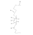
- the splicing terminal 20 is formed by pressing a plate material made of a metal plate having excellent conductivity, for example, copper or a copper alloy, and applying Sn (tin) plating. As shown, the press contact terminal 30 and the crimp terminal 40 are arranged side by side and connected to each other. The crimp terminal 40 is connected to the end of the copper wire 15 that is a branch line, and has a shape in which an insulation barrel 42 is connected to the front side of the wire barrel 41.
- the wire barrel 41 is caulked and crimped to the end of the core wire 16 that is peeled and exposed in the copper electric wire 15, and a pair of wide barrel pieces 41 ⁇ / b> A are opposed to each other from the left and right side edges of the bottom plate 43.
- the barrel pieces 41A are squeezed into a so-called heart shape by embrace the outer periphery of the end of the core wire 16 from both the left and right sides while abutting the protruding ends of the barrel pieces 41A.
- the insulation barrel 42 is caulked and crimped to the end of the remaining insulation coating 18, and a pair of left and right barrel pieces 42 ⁇ / b> A that are narrower and taller than the barrel pieces 41 ⁇ / b> A on the wire barrel 41 side,
- the barrel plate 42A is formed so as to be shifted from the left and right side edges of the bottom plate 43 in the front-rear direction, and the barrel pieces 42A wrap the respective protruding ends back and forth while embrace the outer periphery of the terminal of the insulating coating 18 from both the left and right sides It can be caulked.
- a connection portion 44 is formed on the back side of the wire barrel 41 in a form that is raised from the back edge of the bottom plate 43 at a right angle.
- the press contact terminal 30 is connected to an intermediate position in the length direction of the aluminum wire 10 which is a main wire, and a pair of press contact blades 32 are formed at right angles from both front and rear ends of a substrate 31 that is slightly long in the front and rear direction. Shape.
- a press-contact groove 33 is formed at the center of each press-contact blade 32 in the width direction so as to open to the upper edge. Note that an introduction portion 35 is formed at the upper end portion, that is, the inlet of the pressure contact groove 33, and expands upward.
- the groove width of the pressure contact groove 33 is smaller than the diameter of the core wire 11 of the aluminum electric wire 10. Further, the depth of the pressure contact groove 33 is about 1.5 times the diameter of the aluminum electric wire 10.
- the crimp terminal 40 and the press contact terminal 30 having the above-described structure are arranged side by side in the left-right direction at a predetermined interval.
- the connection portion 44 at the back end of the press contact terminal 40 and the press contact on the back side of the press contact terminal 30 are arranged.
- a splicing terminal 20 in which the crimp terminal 40 and the press contact terminal 30 are integrated is formed by passing the elongated connection plate 22 between the lower side of the left edge of the blade 32.
- a housing 50 in which the above-described splicing terminal 20 is accommodated is provided.
- the housing 50 is made of synthetic resin.
- a cover 52 attached to the upper surface of the housing main body 51 is provided on the side of the housing main body 51 via a hinge 53. It is integrally formed.
- the housing body 51 has two left and right mounting recesses 55 and 56.
- the crimp terminal 40 that is crimped to the end of the copper wire 15 can be mounted.
- the crimp terminal 40 moves in the front-rear direction. It is impossible to position and fit.
- An electric wire receiving portion 57 for receiving the lower surface of the copper electric wire 15 drawn from the crimp terminal 40 is formed on the front side of the left mounting recess 55.
- the bottom portion of the press contact terminal 30 can be mounted in the right mounting recess 56. Specifically, the bottom portion of the press contact terminal 30 is tightly fitted so that it cannot move in the front-rear and left-right directions. Yes.
- An electric wire receiving portion 57 for receiving the lower surface of the aluminum electric wire 10 drawn from both the front and rear sides of the press contact terminal 30 is formed to extend on both the near side and the deep side of the right mounting recess 56.
- a mounting groove 59 in which the lower part of the connection plate 22 fits tightly is formed so as to connect the back surfaces of the left and right mounting recesses 55.56.
- the cover 52 is attached to the upper surface of the housing 50 in a posture in which the hinge 53 is bent and reversed from FIG. 3 and is locked in a properly attached form by a lock mechanism (not shown). It has become. Although the cover 52 is partially omitted, the cover 52 is fitted to cover the upper surface side of the crimp terminal 40 that is crimped and crimped to the end of the copper wire 15, and extends to the front side of the crimp terminal 40.
- a wire receiving portion 61 is formed that sandwiches the upper surface of the extracted copper wire 15 with the wire receiving portion 57 on the housing body 51 side.
- a holding portion 63 that protrudes to a position immediately above the aluminum wire 10 that has been press-fitted to a position is formed so as to project, and the upper surface of the aluminum wire 10 drawn out from both the front and rear sides of the press contact terminal 30 is connected to the wire receiving portion 58 on the housing body 51 side.
- An electric wire receiving portion (not shown) sandwiched between the two is formed.
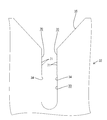
- the release teeth 70 for peeling the oxide film formed on the surface of the core wire 11 in the aluminum electric wire 10 (the release of the present invention). Equivalent to the portion). More specifically, as shown in FIG. 7, peeling teeth 70 are formed in a substantially upper half region near the introduction portion 35 in the left and right groove edges 34 of the pressure contact groove 33 in each pressure contact blade 32. The peeling teeth 70 are formed by connecting a plurality of tooth portions 71 in the vertical direction. Each tooth portion 71 is basically formed in a mountain shape with a sharp tip, but as shown in FIG.
- the upper slope 72 has a gentle inclination angle ⁇ of less than 45 degrees (for example, about 30 degrees).
- the lower slope 73 is formed in a mountain shape that forms a steep slope whose slope angle ⁇ exceeds 45 degrees (for example, about 60 degrees).
- the terminal of the copper wire 15 that is a branch line is connected to the crimp terminal 40 of the splice terminal 20.
- the end of the insulating coating 18 is peeled off, and the end of the core wire 16 is exposed over a predetermined length.
- the splicing terminal 20 is set in a crimping device provided with an anvil and a crimper, and the exposed end of the core wire 16 is connected to the wire barrel 41 of the crimping terminal 40 and also to the insulation barrel 42.
- the crimp terminal 40 of the splice terminal 20 is connected to the end of the copper wire 15 that is a branch line.
- the splicing terminal 20 connected to the end of the copper wire 15 is attached to the housing body 51 in the opened housing 50 as shown in FIG. Specifically, the bottom portion of the pressure contact terminal 30 in the splicing terminal 20 is tightly fitted in the right mounting recess 56, and the lower portion of the connection plate 22 is crimped and crimped to the end of the copper wire 15 while being fitted in the mounting groove 59.
- the crimp terminal 40 is mounted in the left mounting recess 55. The copper wire 15 drawn out from the crimp terminal 40 is received by the wire receiving portion 57.
- the splicing terminal 20 connected to the terminal of the copper wire 15 is set to the lower mold of the pressure welding apparatus. Then, as shown by a chain line in FIG. 3, a predetermined portion in the length direction of the aluminum wire 10 which is the main line is arranged above the press contact terminal 30 of the splicing terminal 20. After that, the upper die of the pressure welding device is lowered, and the pushing portion provided on the upper die is located at the position between the pressure welding blades 32 in the pressure welding terminal 30 and at the position outside each pressure welding blade 32 as shown in FIG. As shown by the arrow, the aluminum electric wire 10 is pushed downward.
- the aluminum wire 10 is press-fitted into the press-contact groove 33 of the press-contact blade 32 corresponding to the press-contact terminal 30 at two predetermined positions.
- the aluminum electric wire 10 is press-fitted into the pressure contact groove 33 while being guided by the introduction portion 35, and the insulating coating 13 is cut at a slightly pointed portion 33 ⁇ / b> A at the upper end of the pressure contact groove 33, so that the exposed core wire 11 is formed in the pressure contact groove 33.
- the groove edges 34 are pushed in contact with each other.
- the aluminum electric wire 10 has a circumstance that an oxide film is easily formed on the surface of the core wire 11 made of an aluminum wire, and an oxide film may be formed on the surface of the core wire 11 from the manufacturing stage of the aluminum electric wire 10. Concerned. Therefore, if both the groove edges 34 of the pressure contact groove 33 have a smooth structure, even when the exposed core wire 11 is pushed down in the pressure contact groove 33, the surface oxide film is pushed so as to slide along the groove edge 34. There is a risk that it will remain. If it does so, since the core wire 11 and the press-contact blade 32 of the aluminum electric wire 10 will be electrically connected in the state which the oxide film intervened, there exists a problem that an electrical resistance becomes large.
- the left and right groove edges 34 of the press contact groove 33 in each press contact blade 32 are formed with peeling teeth 70 in a substantially upper half region close to the introduction portion 35, as shown in FIG.
- the peeling teeth 70 on both sides come into sliding contact with the surface of the core wire 11, and more specifically, the peeling teeth 70.
- the new surface of the surface of the core wire 11 formed by peeling the oxide film is the lower side of the groove edges 34 of the pressure contact groove 33. It will be in the state which contacted the smooth area
- the upper die of the pressure welding device is lifted and retracted, and then the cover 52 is reversed and attached to the upper surface of the housing body 51 while the hinge 53 is bent. Locked. Along with this, the holding portion 63 of the cover 52 advances to a position immediately above the press-contacted aluminum wire 10, and the aluminum wire 10 is pressed and held at the normal press-contact position. After that, the assembled housing 50 is removed from the pressure welding apparatus, and the work of branching and connecting the copper wire 15 as the branch line to the aluminum wire 10 as the main line is completed.
- the new surface in a state where the oxide film on the surface of the core wire 11 is peeled is in contact with the groove edge 34 of the press contact groove 33 of the press contact terminal 30.
- the electrical resistance is kept small, and the electrical performance is improved.
- the plurality of tooth portions 71 having a mountain shape with sharp tips are formed on both groove edges 34 of the press contact groove 33 of the press contact blade 32. Since the continuous peeling teeth 70 are formed, the peeling teeth 70 are exposed after the insulating coating 13 is cut open as the aluminum electric wire 10 is press-fitted into the pressing groove 33 of the pressing blade 32.
- the oxide film formed on the surface of the core wire 11 is peeled off, and the new surface of the surface of the core wire 11 comes into contact with the groove edge 34 of the press contact groove 33.
- the electrical resistance of the contact part of the core wire 11 and the press-contact blade 32, ie, the press-contact part of the aluminum electric wire 10 is suppressed small, and electrical performance is improved as a result.
- the peeling teeth 70 are formed only in the almost half area on the inlet side in the groove edge 34 of the pressure contact groove 33. Therefore, at the initial stage of press-fitting of the aluminum electric wire 10, the peeling teeth 70 come into sliding contact with the surface of the core wire 11 to peel off the oxide film, and at the final stage of press-fitting, the groove edge in the region where the peeling teeth 70 are not present on the surface of the core wire 11. 34 is in sliding contact.
- the press-fitting resistance at the final stage of press-fitting can be suppressed to reduce the press-fitting as a whole, and when the press-fitting is completed, the new surface of the core wire 11 comes into contact with the region without the separation teeth 70 in the groove edge 34 of the press-fitting groove 33. Therefore, the contact area can be increased, and the reliability of electrical connection is increased.
- the peeling tooth 70 has a shape in which a plurality of tooth portions 71 having a mountain shape with a sharp tip are arranged along the press-fitting direction (vertical direction) of the aluminum electric wire 10, and constitutes the peeling tooth 70.
- the front side (upper side) slope 72 in the press-fitting direction of the aluminum electric wire 10 is formed as a gentle slope
- the back side (lower side) slope 73 is formed as a steep slope. Therefore, when the exposed core wire 11 in the aluminum electric wire 10 is pushed along the pressure contact groove 33, the pointed tip of each tooth portion 71 constituting the peeling tooth 70 sequentially comes into sliding contact with the surface of the core wire 11.
- the oxide film formed on the surface of the core wire 11 is surely peeled off. Further, when the exposed core wire 11 in the aluminum electric wire 10 is pushed along the press-contact groove 33, the press-fitting resistance is suppressed to be small because the gradual slope side of the mountain in each tooth portion 71 is sequentially brought into sliding contact, and press-fitting is completed. After that, it is difficult to come out from the press contact groove 33 by being locked to the steep slope side.
- the aluminum wire 10 is particularly arranged depending on the mounting position of the harness in which the copper wire 15 that is the branch line is branched and connected to the aluminum wire 10 that is the main wire using the splice terminal 20.
- the core wire 11 of the aluminum electric wire 10 repeatedly contracts and expands, In particular, when contracted, there is a concern that a gap is formed between the core wire 11 and the groove edge 34 of the pressure contact groove 33, and another contact resistance is generated.
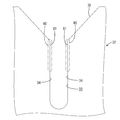
- Embodiment 2 is a further improvement to solve the above problems. That is, as shown in FIG. 9, peeling teeth 70 are formed over almost the entire height of the left and right groove edges 34 of the press contact groove 33 in each press contact blade 32 of the press contact terminal 30. As in the case of the first embodiment, the peeling tooth 70 has a plurality of teeth 71 each having a mountain shape in which the tip is sharp, the upper slope 72 is a gentle slope, and the lower slope 73 is a steep slope. It is formed by that.
- the peeling tooth 70 continues to slidably contact the surface of the core wire 11 while the exposed core wire 11 in the aluminum electric wire 10 is pushed to the normal position along the groove edge 34 of the press contact groove 33.
- the peeling tooth 70 functions to peel off the oxide film on the surface of the core wire 11 particularly in the upper region of the pressure contact groove 33, and the peeling tooth 70 is rather the core wire in the lower region including the normal press-fitting position. It functions to bite into 11 new surfaces. Therefore, when the aluminum electric wire 10 is in the pressure welding completion position, even when the pressure welding portion is cooled and the core wire 11 contracts, the peeling teeth 70 are in a state of being bitten into the surface of the core wire 11. The contact state between the pressure contact groove 33 and the groove edge 34 is maintained, and the occurrence of contact resistance is prevented.
- FIG. 10 shows Embodiment 3 of the present invention.
- the press contact terminal is usually formed into a predetermined shape by cutting and bending a copper or copper alloy plate by a press machine, and then Sn (tin) by so-called soaking. Plating is applied.
- Sn titanium
- Plating is applied in the upper and lower half regions 80 near the introduction portion 35 of the right and left groove edges 34 of the press contact groove 33 in the press contact blade 32.
- masking is performed before the plating process is performed.
- the groove edge 34 is held on the original cut surface as it was cut, and as a result, a peeling portion 81 made of a relatively rough surface with irregularities is formed.
- the peeling portions 81 on both sides of the core wire 11 are formed.
- the surface of the core wire 11 is slid in contact with the surface of the core wire 11 in sequence, and the oxide film formed on the surface of the core wire 11 is peeled off.
- the new surface of the surface of the core wire 11 formed by peeling off the oxide film is the Sn-plated region on the lower side of the groove edges 34 of the pressure contact groove 33.
- the present invention is not limited to the embodiments described with reference to the above description and drawings.
- the following embodiments are also included in the technical scope of the present invention.
- the chevron shape of the tooth portion constituting the peeling tooth may be an arbitrary shape such that the upper surface side and the lower surface side are inclined surfaces having the same inclination angle, or the upper surface side is an inclined surface and the lower surface side is a horizontal surface. it can.
- (3) The peeling tooth may be provided with a plurality of tooth portions arranged at intervals.
- the form of the press contact terminal may be such that the position in the left-right direction is shifted between the two front and rear press contact blades. Moreover, the press contact blade may be one, or conversely, three or more may be provided. (5) In the male terminal or the female terminal connected to the terminal of the covered electric wire, the press contact terminal may be provided in place of the crimping part (barrel) behind the connection part connected to the counterpart terminal. Good.
- two pressure contact terminals may be arranged in the horizontal direction and connected to each other.
- the present invention can be similarly applied to a case where a plurality of press contact terminals are arranged in the horizontal direction and connected to each other to form a joint terminal.
- the aluminum electric wire was illustrated as a covered electric wire press-contacted to a press-contact terminal, it is possible to apply also about other electric wires, such as a copper electric wire.
- the original cut surface (peeling portion) in a state where the surface treatment by plating is not performed is also applied to the length region on the inner side of the groove edge of the press contact groove corresponding to the press-fit completion position of the covered electric wire. It may be formed.
Abstract
圧接刃32における圧接溝33の両溝縁34には、アルミ電線10の露出した芯線11の表面に摺接可能な剥離歯70が形成されている。アルミ電線10が圧接刃32の圧接溝33に圧入されると、絶縁被覆13が切開されることで芯線11が露出されるとともに、剥離歯70が芯線11の表面に摺接することで、芯線11の表面に形成された酸化被膜が剥ぎ取られる。圧入が完了した時点では、芯線11の表面の新生面と、圧接溝33における剥離歯70が形成されていない溝縁34とが接触する。
Description
本発明は、圧接端子、スプライス用端子及び電線の圧接構造に関する。
従来、例えば本線から分岐線を分岐して接続するためのスプライス用端子や、複数の電線を接続するためのジョイント用端子として、圧接端子が使用されている(例えば、特許文献1参照)。
この圧接端子は、導電性に優れた金属板をプレス加工して形成され、導電性の芯線の回りを絶縁被覆で覆った被覆電線が圧入可能な圧接溝が設けられた圧接刃を備えた構造であって、被覆電線を圧接刃の圧接溝内に圧入すると、絶縁被覆が溝縁で切開されつつ芯線が露出され、露出した芯線が圧接溝の溝縁に接触することで電気的導通が取られるようになっている。
特開平10-275639号公報
この圧接端子は、導電性に優れた金属板をプレス加工して形成され、導電性の芯線の回りを絶縁被覆で覆った被覆電線が圧入可能な圧接溝が設けられた圧接刃を備えた構造であって、被覆電線を圧接刃の圧接溝内に圧入すると、絶縁被覆が溝縁で切開されつつ芯線が露出され、露出した芯線が圧接溝の溝縁に接触することで電気的導通が取られるようになっている。
ところで近年、自動車のワイヤハーネス等の分野においても、被覆電線について軽量化等を目的としてアルミ電線を使用するようになった。アルミ電線は例えば、アルミニウムまたはアルミニウム合金製の複数本のアルミ素線を撚り合わせた撚り線からなる芯線を絶縁被覆で覆った構造である。一方この種のアルミ電線では、芯線が外気に晒されることで芯線の表面に酸化被膜ができやすいという事情があり、被覆電線の製造段階から芯線の表面に酸化被膜が形成されていることが懸念される。
したがって、圧接端子に圧接される被覆電線がアルミ電線の場合は、絶縁被覆が切開されて露出した芯線が圧接溝の溝縁に接触する際に、芯線の表面に形成された酸化被膜が介在した状態で電気的な接続がなされるために、電気抵抗が大きくなるという問題がある。
なお、アルミ電線以外に例えば銅電線の場合も、少量ではあるかも知れないが芯線の表面に酸化被膜が形成されることが懸念され、圧接端子への圧接部分において電気抵抗が大きくなるという問題は、同様に生ずるところである。
本発明は上記のような事情に基づいて完成されたものであって、その目的は、被覆電線を圧接端子の圧接刃に圧接した部分において電気抵抗が増大することを防ぐところにある。
なお、アルミ電線以外に例えば銅電線の場合も、少量ではあるかも知れないが芯線の表面に酸化被膜が形成されることが懸念され、圧接端子への圧接部分において電気抵抗が大きくなるという問題は、同様に生ずるところである。
本発明は上記のような事情に基づいて完成されたものであって、その目的は、被覆電線を圧接端子の圧接刃に圧接した部分において電気抵抗が増大することを防ぐところにある。
本発明の圧接端子は、導電性の芯線の周りを絶縁被覆で覆ってなる被覆電線が圧入可能な圧接溝を有し、被覆電線を前記圧接溝内に圧入することにより、絶縁被覆が切開されて露出した芯線が前記圧接溝の溝縁に接触して導通される圧接刃と、前記圧接刃における前記圧接溝の両溝縁のうち少なくとも一方の溝縁に形成され、露出した芯線の表面に摺接可能な剥離部とを備えているところに特徴を有する。
また、本発明の電線の圧接構造は、導電性の芯線の回りを絶縁被覆で覆った被覆電線が、上記に特定された圧接端子に圧接接続されているところに特徴を有する。
また、本発明の電線の圧接構造は、導電性の芯線の回りを絶縁被覆で覆った被覆電線が、上記に特定された圧接端子に圧接接続されているところに特徴を有する。
上記の構成によれば、被覆電線が圧接刃の圧接溝に圧入されると、圧接溝の両溝縁が絶縁被覆を切開することで芯線が露出されるとともに、溝縁に設けられた剥離部が芯線の表面に摺接することで、芯線の表面に形成された酸化被膜を剥ぎ取り、芯線の表面の新生面と圧接溝の溝縁とが接触する。これにより、芯線と圧接刃の接触部分、すなわち被覆電線の圧接部分の電気抵抗が小さく抑えられ、電気性能が高められる。
なお、圧接端子において以下のような構成としてもよい。
(1)前記剥離部は、絶縁被覆が切開されたのち露出した芯線の表面に摺接することで、芯線の表面に形成された被膜を剥ぎ取り、芯線の表面の新生面を前記圧接溝の溝縁と接触させるものである。
(2)前記剥離部は、前記圧接溝の溝縁における被覆電線の圧入方向の手前側の長さ領域にのみ形成されている。
被覆電線の圧入の初めの段階において、剥離部が芯線の表面に摺接して酸化被膜を剥ぎ取り、圧入の終盤では芯線の表面には剥離部のない領域の溝縁が摺接する。圧入の終盤における圧入抵抗が小さく抑えられて全体としての圧入力が少なくて済み、また圧入の完了時には、芯線の新生面が溝縁における剥離部のない領域と接触するために接触面積を大きく取ることができる。
(3)前記剥離部は、前記圧接溝の溝縁における被覆電線の圧入方向の手前側の長さ領域と、被覆電線の圧入完了位置と対応した前記圧接溝の溝縁における奥側の長さ領域とに形成されている。
ハーネス等の搭載箇所により、被覆電線を圧接端子へ圧接した部分が冷却と加熱とが繰り返される過酷な状況下に置かれると、芯線が収縮と膨張とを繰り返し、特に収縮した場合に、芯線と圧接溝の溝縁との間に隙間ができ、別の接触抵抗が発生するおそれがある。
その点この構成によれば、圧入の完了時点で、剥離部が芯線の表面に食い込んだ状態となり、芯線が収縮した際にも接触状態が維持され、接触抵抗の発生が防止される。
(4)前記剥離部が、先端が尖った山形をなす歯部が被覆電線の圧入方向に沿って複数並んで設けられた剥離歯である。剥離歯を構成する各歯部の尖った先端が芯線の表面に順次に摺接することで、酸化皮膜を効果的に剥ぎ取ることができる。
(5)前記剥離歯を構成する各歯部は、被覆電線の圧入方向の手前側が緩斜面で奥側が急斜面をなす山形に形成されている。被覆電線を圧入する際には、各歯部における山の緩斜面側を順次に摺接することから圧入抵抗を小さく抑えられ、圧入が完了したのちは、急斜面側に係止されることで、圧接溝から抜け難くなる。
(6)前記剥離部が、メッキによる表面処理が施されていない状態の原切断面により形成されている。メッキによる表面処理が施されていない原切断面は、凹凸のある粗い面となっており、その粗い面が芯線の表面に順次に摺接することにより、酸化皮膜が剥ぎ取られる。
さらに、次のような構成としてもよい。
(7)上記に特定された圧接端子に、導電性の芯線の回りを絶縁被覆で覆った別の被覆電線の端末に圧着により接続される圧着端子が接続されてスプライス用端子が形成されている。当該スプライス用端子によれば、本線に分岐線を分岐して接続する場合に、本線の途中位置を圧接端子に圧接する一方、分岐線についてはその端末を圧着端子に圧着するといった使い方ができる。
(8)導電性の芯線の回りを絶縁被覆で覆った被覆電線が、スプライス用端子における前記圧接端子に圧接接続されている。
(9)前記被覆電線が、複数本のアルミニウム又はアルミニウム合金製のアルミ素線からなる芯線を絶縁被覆で覆ったアルミ電線である。酸化被膜ができやすいアルミ電線について、特に有用となる。
本発明によれば、被覆電線を圧接端子の圧接刃に圧接した部分において電気抵抗が増大することを防止できる。
10…アルミ電線(被覆電線)
11…芯線
13…絶縁被覆
15…銅電線(別の被覆電線)
16…芯線
17…銅素線
18…絶縁被覆
20…スプライス用端子
22…接続板
30…圧接端子
32…圧接刃
33…圧接溝
34…(圧接溝33の)溝縁
70…剥離歯(剥離部)
71…歯部
72…(上側の)斜面
73…(下側の)斜面
81…剥離部
11…芯線
13…絶縁被覆
15…銅電線(別の被覆電線)
16…芯線
17…銅素線
18…絶縁被覆
20…スプライス用端子
22…接続板
30…圧接端子
32…圧接刃
33…圧接溝
34…(圧接溝33の)溝縁
70…剥離歯(剥離部)
71…歯部
72…(上側の)斜面
73…(下側の)斜面
81…剥離部
以下、本発明の実施形態を添付図面に基づいて説明する。
<実施形態1>
本発明の実施形態1を図1ないし図8によって説明する。
この実施形態では、電源線等の本線に対して、エアバッグシステム用の信号線等の分岐線を分岐して接続する場合を例示しており、この分岐接続に適用するスプライス用端子20の一部に、本発明に係る圧接端子30が適用されている。
<実施形態1>
本発明の実施形態1を図1ないし図8によって説明する。
この実施形態では、電源線等の本線に対して、エアバッグシステム用の信号線等の分岐線を分岐して接続する場合を例示しており、この分岐接続に適用するスプライス用端子20の一部に、本発明に係る圧接端子30が適用されている。
本線にはアルミ電線10が使用されており、アルミ電線10は、図4に示すように、アルミニウムまたはアルミニウム合金製の素線を複数本撚り合せた撚り線によって芯線11が形成され、この芯線11の回りが合成樹脂製の絶縁被覆13で覆われた構造である。なお、図4ないし図6では、複数のアルミ素線からなる芯線11の断面を、全体として模式的に図示している。
一方の分岐線には銅電線15が使用されており、銅電線15は、図2に示すように、銅または銅合金製の素線17を複数本撚り合せた撚り線によって芯線16が形成され、この芯線16の回りが合成樹脂製の絶縁被覆18で覆われた構造となっている。
一方の分岐線には銅電線15が使用されており、銅電線15は、図2に示すように、銅または銅合金製の素線17を複数本撚り合せた撚り線によって芯線16が形成され、この芯線16の回りが合成樹脂製の絶縁被覆18で覆われた構造となっている。
スプライス用端子20は、導電性に優れた金属板製、例えば銅または銅合金製の板材がプレス加工されるとともに、Sn(錫)メッキが施されて形成されており、図1及び図2に示すように、圧接端子30と圧着端子40とが横並びして互いに接続された形状となっている。
圧着端子40は、分岐線である銅電線15の端末が接続されるものであって、ワイヤバレル41の手前側に、インシュレーションバレル42が連ねて設けられた形状である。
圧着端子40は、分岐線である銅電線15の端末が接続されるものであって、ワイヤバレル41の手前側に、インシュレーションバレル42が連ねて設けられた形状である。
ワイヤバレル41は、銅電線15における皮剥きされて露出された芯線16の端末にかしめ圧着されるものであって、底板43の左右の側縁から一対の幅広のバレル片41Aが互いに対向するようにして立ち上がり形成されており、両バレル片41Aがそれぞれの突出端を突き合わせつつ、芯線16の端末の外周を左右両側から抱き込むようにして、いわゆるハート型にかしめられるようになっている。
インシュレーションバレル42は、残された絶縁被覆18の端末にかしめ圧着されるものであって、ワイヤバレル41側のバレル片41Aよりも幅狭で逆に背が高い左右一対のバレル片42Aが、底板43の左右の側縁から前後にずれた形態で立ち上がり形成されており、両バレル片42Aがそれぞれの突出端を前後にラップさせつつ、絶縁被覆18の端末の外周を左右両側から抱き込むようにしてかしめられるようになっている。
なお、ワイヤバレル41の奥側には、底板43の奥縁から直角に立ち上げられた形態で接続部44が形成されている。
なお、ワイヤバレル41の奥側には、底板43の奥縁から直角に立ち上げられた形態で接続部44が形成されている。
圧接端子30は、本線であるアルミ電線10における長さ方向の途中位置が接続されるものであって、前後方向にやや長い基板31の前後両端から、一対の圧接刃32が直角に立ち上がり形成された形状である。各圧接刃32における幅方向の中央部には、圧接溝33が上縁に開口して形成されている。なお、圧接溝33の上端部すなわち入口には、上方に向けて先拡がりとなった導入部35が形成されている。圧接溝33の溝幅は、アルミ電線10の芯線11の直径よりも小さい寸法となっている。また、圧接溝33の深さは、アルミ電線10の直径の約1.5倍となっている。
上記のような構造になる圧着端子40と圧接端子30とが、所定間隔を開けて左右方向に並んで配され、圧着端子40の奥端の接続部44と、圧接端子30における奥側の圧接刃32の左側縁の下部側との間に、細長い接続板22が渡されることにより、圧着端子40と圧接端子30とが一体化されたスプライス用端子20が形成されている。
上記したスプライス用端子20が収容されるハウジング50が設けられている。このハウジング50は合成樹脂製であって、成形状態では、図3に示すように、ハウジング本体51の側方に、同ハウジング本体51の上面に被着されるカバー52が、ヒンジ53を介して一体形成されている。
ハウジング本体51には、左右2個の装着凹部55,56が形成されている。左側(ヒンジ53が形成された側)の装着凹部55には、銅電線15の端末にかしめ圧着された状態の圧着端子40が装着可能であって、特に同圧着端子40は、前後方向について移動不能に位置決めされて嵌められるようになっている。左側の装着凹部55の手前側には、圧着端子40から引き出された銅電線15の下面を受ける電線受け部57が延出形成されている。
ハウジング本体51には、左右2個の装着凹部55,56が形成されている。左側(ヒンジ53が形成された側)の装着凹部55には、銅電線15の端末にかしめ圧着された状態の圧着端子40が装着可能であって、特に同圧着端子40は、前後方向について移動不能に位置決めされて嵌められるようになっている。左側の装着凹部55の手前側には、圧着端子40から引き出された銅電線15の下面を受ける電線受け部57が延出形成されている。
一方、右側の装着凹部56には、圧接端子30の底部が装着可能となっており、詳細には、圧接端子30の底部が、前後及び左右方向の移動不能に緊密に嵌められるようになっている。右側の装着凹部56の手前側と奥側の両方には、圧接端子30の前後両側から引き出されたアルミ電線10の下面を受ける電線受け部57が延出形成されている。
なお、左右の装着凹部55.56の奥面同士を結ぶようにして、接続板22の下部が緊密に嵌る装着溝59が形成されている。
なお、左右の装着凹部55.56の奥面同士を結ぶようにして、接続板22の下部が緊密に嵌る装着溝59が形成されている。
カバー52は、ヒンジ53を折り曲げつつ、図3とは表裏反転させた姿勢でハウジング50の上面に被着され、ロック機構(図示せず)により、正規に被着された形態にロックされるようになっている。カバー52は、一部省略して図示されているが、銅電線15の端末にかしめ圧着された状態の圧着端子40の上面側を嵌めて覆う装着凹部60と、圧着端子40の手前側に延出された銅電線15の上面を、ハウジング本体51側の電線受け部57との間で挟む電線受け部61が形成されている。
またカバー52には、同カバー52が正規に被着された場合に、図6の鎖線に示すように、圧接端子30における前後両圧接刃32の間の位置において、詳しくは後記するように正規位置まで圧入されたアルミ電線10の直上位置まで達する保持部63が突出形成されているとともに、圧接端子30の前後両側から引き出されたアルミ電線10の上面を、ハウジング本体51側の電線受け部58との間で挟む電線受け部(図示せず)が形成されている。
さて、上記したスプライス用端子20を構成する圧接端子30の前後の圧接刃32には、アルミ電線10における芯線11の表面に形成された酸化被膜を剥離するための剥離歯70(本発明の剥離部に相当)が形成されている。
より詳細には、図7に示すように、各圧接刃32における圧接溝33の左右の溝縁34のうち、導入部35に近いほぼ上半分の領域において、剥離歯70が形成されている。剥離歯70は、複数の歯部71を上下方向に連ねることで形成されている。各歯部71は基本的には、先端が尖った山形に形成されているが、図8に示すように、上側の斜面72が、傾斜角αが45度未満(例えば30度程度)の緩斜面で、一方、下側の斜面73が、傾斜角βが45度を越えた(例えば60度程度)の急斜面をなす山形に形成されている。
より詳細には、図7に示すように、各圧接刃32における圧接溝33の左右の溝縁34のうち、導入部35に近いほぼ上半分の領域において、剥離歯70が形成されている。剥離歯70は、複数の歯部71を上下方向に連ねることで形成されている。各歯部71は基本的には、先端が尖った山形に形成されているが、図8に示すように、上側の斜面72が、傾斜角αが45度未満(例えば30度程度)の緩斜面で、一方、下側の斜面73が、傾斜角βが45度を越えた(例えば60度程度)の急斜面をなす山形に形成されている。
続いて、本実施形態の作用を説明する。
スプライス作業の一例を示すと、以下のようである。まず、スプライス用端子20の圧着端子40に対して、分岐線である銅電線15の端末が接続される。銅電線15では、絶縁被覆18の端末が皮剥きされて、芯線16の端末が所定長さに亘って露出状態とされる。一方、スプライス用端子20は、アンビルとクリンパとが備えられた圧着装置にセットされ、圧着端子40のワイヤバレル41に対して、露出された芯線16の端末が、またインシュレーションバレル42に対して、残された絶縁被覆18の端末がそれぞれ配され、両バレル41,42は、アンビルとクリンパとの間で挟圧されてかしめられる。これにより、図2に示すように、ワイヤバレル41は、芯線16の端末に対してハート型にかしめられ、また、インシュレーションバレル42は、絶縁被覆18の端末に対して前後にラップした形態でかしめられる。逆の言い方をすると、分岐線である銅電線15の端末に、スプライス用端子20の圧着端子40が接続されたことになる。
スプライス作業の一例を示すと、以下のようである。まず、スプライス用端子20の圧着端子40に対して、分岐線である銅電線15の端末が接続される。銅電線15では、絶縁被覆18の端末が皮剥きされて、芯線16の端末が所定長さに亘って露出状態とされる。一方、スプライス用端子20は、アンビルとクリンパとが備えられた圧着装置にセットされ、圧着端子40のワイヤバレル41に対して、露出された芯線16の端末が、またインシュレーションバレル42に対して、残された絶縁被覆18の端末がそれぞれ配され、両バレル41,42は、アンビルとクリンパとの間で挟圧されてかしめられる。これにより、図2に示すように、ワイヤバレル41は、芯線16の端末に対してハート型にかしめられ、また、インシュレーションバレル42は、絶縁被覆18の端末に対して前後にラップした形態でかしめられる。逆の言い方をすると、分岐線である銅電線15の端末に、スプライス用端子20の圧着端子40が接続されたことになる。
上記のように、銅電線15の端末に接続されたスプライス用端子20が、図3に示すように、開いた状態のハウジング50におけるハウジング本体51に装着される。詳細には、スプライス用端子20における圧接端子30の底部が右側の装着凹部56に緊密に嵌められ、また接続板22の下部が装着溝59に嵌められつつ、銅電線15の端末にかしめ圧着された圧着端子40が左側の装着凹部55内に装着される。圧着端子40から引き出された銅電線15は、電線受け部57で受けられる。
このように、銅電線15の端末に接続されたスプライス用端子20が、詳しくは図示しないが、圧接装置の下型に対してセットされる。そうしたら、図3の鎖線に示すように、本線であるアルミ電線10の長さ方向の途中の所定箇所が、スプライス用端子20の圧接端子30の上方に配される。そののち、圧接装置の上型が下降操作され、上型に設けられた押込部が、圧接端子30における両圧接刃32の間の位置と、各圧接刃32の外側の位置において、図4の矢線に示すように、アルミ電線10を下方に押し込む。
これによりアルミ電線10は、所定の前後2箇所が、圧接端子30における対応する圧接刃32の圧接溝33に対して圧入される。アルミ電線10は、導入部35で案内されつつ圧接溝33に圧入され、圧接溝33の上端のやや尖った部分33Aで絶縁被覆13が切開され、これにより露出された芯線11が圧接溝33の両溝縁34に接触しつつ押し込まれるようになっている。
ここで、特にアルミ電線10は、アルミ素線からなる芯線11の表面に酸化被膜ができやすいという事情があり、アルミ電線10の製造段階から芯線11の表面に酸化被膜が形成されていることも懸念される。そのため、仮に圧接溝33の両溝縁34が平滑な構造であると、露出した芯線11が圧接溝33内を押し下げられる場合も、表面の酸化被膜が溝縁34に沿って滑るように押し込まれ、そのまま残るおそれがある。そうすると、アルミ電線10の芯線11と圧接刃32とが酸化被膜が介在した状態で電気的に接続されることになるため、電気抵抗が大きくなるという問題がある。
それに対して本実施形態では、各圧接刃32における圧接溝33の左右の溝縁34には、導入部35に近いほぼ上半分の領域に剥離歯70が形成されているから、図5に示すように、アルミ電線10の絶縁被膜13が切開されて露出された芯線11が圧接溝33に押し込まれると、両側の剥離歯70が芯線11の表面に摺接し、より詳細には、剥離歯70を構成する各歯部71の尖った先端が順次に芯線11の表面に摺接し、これにより芯線11の表面に形成された酸化被膜が剥ぎ取られる。
そして、アルミ電線10が正規位置まで押し込まれると、図6に示すように、酸化被膜が剥離されることで形成された芯線11の表面の新生面が、圧接溝33の両溝縁34における下側の平滑な領域と接触した状態となる。
そして、アルミ電線10が正規位置まで押し込まれると、図6に示すように、酸化被膜が剥離されることで形成された芯線11の表面の新生面が、圧接溝33の両溝縁34における下側の平滑な領域と接触した状態となる。
上記のようにアルミ電線10の正規の圧接作業が終了したら、圧接装置の上型が上昇退避し、そののちヒンジ53を屈曲させつつカバー52が反転してハウジング本体51の上面に被着されてロックされる。これに伴い、カバー52の保持部63が圧接されたアルミ電線10の直上位置まで進出し、アルミ電線10が正規の圧接位置に押圧保持されることになる。そののち、組み付けられたハウジング50が圧接装置から取り外され、本線であるアルミ電線10に、分岐線である銅電線15を分岐接続する作業が完了する。ここで、アルミ電線10を圧接端子30に圧接した部分において、芯線11の表面の酸化被膜が剥離された状態の新生面が、圧接端子30の圧接溝33の溝縁34に接触しているから、電気抵抗が小さく抑えられ、ひいては電気性能が高められる。
以上のように本実施形態によれば、アルミ電線10が圧接される圧接端子30において、圧接刃32における圧接溝33の両溝縁34に、先端が尖った山形をなす複数の歯部71を連ねた剥離歯70が形成された構造となっているから、アルミ電線10が圧接刃32の圧接溝33に圧入されることに伴い、剥離歯70が、絶縁被覆13が切開されたのち露出した芯線11の表面に摺接することで、芯線11の表面に形成された酸化被膜を剥ぎ取り、芯線11の表面の新生面が、圧接溝33の溝縁34と接触することになる。これにより、芯線11と圧接刃32の接触部分、すなわちアルミ電線10の圧接部分の電気抵抗が小さく抑えられ、ひいては電気性能が高められる。
本実施形態では、剥離歯70は、圧接溝33の溝縁34における入口側のほぼ半分の領域に限って形成されている。そのため、アルミ電線10の圧入の初めの段階において、剥離歯70が芯線11の表面に摺接して酸化被膜を剥ぎ取り、圧入の終盤では芯線11の表面には剥離歯70のない領域の溝縁34が摺接することとなる。そのため、圧入の終盤における圧入抵抗が小さく抑えられて全体としての圧入力が少なくて済み、また圧入の完了時には、芯線11の新生面が圧接溝33の溝縁34における剥離歯70のない領域と接触するために接触面積を大きく取ることができ、電気接続の信頼性が高まる。
また、剥離歯70は、先端が尖った山形をなす歯部71がアルミ電線10の圧入方向(上下方向)に沿って複数並んで配された形状であり、かつ、同剥離歯70を構成する各歯部71の山形は、アルミ電線10の圧入方向の手前側(上側)の斜面72が緩斜面で、奥側(下側)の斜面73が急斜面に形成されている。
そのため、アルミ電線10における露出された芯線11が圧接溝33に沿って押し込まれる際、剥離歯70を構成する各歯部71の尖った先端が順次に芯線11の表面に摺接することになるから、芯線11の表面に形成された酸化被膜が確実に剥ぎ取られる。
また、アルミ電線10における露出された芯線11が圧接溝33に沿って押し込まれる際、各歯部71における山の緩斜面側を順次に摺接することから圧入抵抗が小さく抑えられ、圧入が完了したのちは、急斜面側に係止されることで、圧接溝33から抜け難くなる。
そのため、アルミ電線10における露出された芯線11が圧接溝33に沿って押し込まれる際、剥離歯70を構成する各歯部71の尖った先端が順次に芯線11の表面に摺接することになるから、芯線11の表面に形成された酸化被膜が確実に剥ぎ取られる。
また、アルミ電線10における露出された芯線11が圧接溝33に沿って押し込まれる際、各歯部71における山の緩斜面側を順次に摺接することから圧入抵抗が小さく抑えられ、圧入が完了したのちは、急斜面側に係止されることで、圧接溝33から抜け難くなる。
<実施形態2>
次に、本発明の実施形態2を図9によって説明する。
上記実施形態1に例示したように、本線であるアルミ電線10に対して、スプライス用端子20を用いて分岐線である銅電線15を分岐して接続したハーネスの搭載箇所により、特にアルミ電線10をスプライス用端子20の一部を構成する圧接端子30へ圧接した部分が、冷却と加熱とが繰り返される過酷な状況下に置かれると、アルミ電線10の芯線11が収縮と膨張とを繰り返し、特に収縮した場合に、芯線11と圧接溝33の溝縁34との間に隙間ができ、別の接触抵抗が発生することが懸念される。
次に、本発明の実施形態2を図9によって説明する。
上記実施形態1に例示したように、本線であるアルミ電線10に対して、スプライス用端子20を用いて分岐線である銅電線15を分岐して接続したハーネスの搭載箇所により、特にアルミ電線10をスプライス用端子20の一部を構成する圧接端子30へ圧接した部分が、冷却と加熱とが繰り返される過酷な状況下に置かれると、アルミ電線10の芯線11が収縮と膨張とを繰り返し、特に収縮した場合に、芯線11と圧接溝33の溝縁34との間に隙間ができ、別の接触抵抗が発生することが懸念される。
実施形態2は、上記の問題点を解決するべくさらに改良が加えられたものである。すなわち、図9に示すように、圧接端子30の各圧接刃32における圧接溝33の左右の溝縁34には、そのほぼ全高に亘って剥離歯70が形成されている。剥離歯70は、上記実施形態1で例示したと同様に、先端が尖り、かつ上側の斜面72が緩斜面で、下側の斜面73が急斜面となった山形をなす歯部71が複数連ねられることで形成されている。
このような構造であると、アルミ電線10における露出された芯線11が、圧接溝33の溝縁34に沿って正規位置まで押し込まれる間、剥離歯70が芯線11の表面に摺接し続けることになるが、特に圧接溝33の上側の領域では、剥離歯70が芯線11の表面の酸化被膜を剥離することに機能し、正規の圧入位置を含む下側の領域では、剥離歯70はむしろ芯線11の新生面に食い込むように機能する。
したがって、アルミ電線10が圧接完了位置にある場合において、同圧接部分が冷却されて芯線11が収縮した際にも、剥離歯70が芯線11の表面に食い込んだ状態にあった分、芯線11と圧接溝33の溝縁34との間の接触状態が維持され、接触抵抗が発生することが防止される。
したがって、アルミ電線10が圧接完了位置にある場合において、同圧接部分が冷却されて芯線11が収縮した際にも、剥離歯70が芯線11の表面に食い込んだ状態にあった分、芯線11と圧接溝33の溝縁34との間の接触状態が維持され、接触抵抗が発生することが防止される。
<実施形態3>
図10は、本発明の実施形態3を示す。圧接端子は通常、一部既述したように、銅または銅合金製の板材が、プレス加工機により切断及び曲げ加工されることで所定形状に形成され、その後、いわゆるどぶ漬けによってSn(錫)メッキが施されるようになっている。
ここで、本実施形態では、圧接刃32における圧接溝33の左右の溝縁34のうち、導入部35に近いほぼ上半分の領域80では、メッキ処理がなされる前にマスキングが施され、したがって同領域80では、溝縁34が切断時のままの原切断面に留められ、結果、凹凸のある比較的粗い面からなる剥離部81が形成されている。
図10は、本発明の実施形態3を示す。圧接端子は通常、一部既述したように、銅または銅合金製の板材が、プレス加工機により切断及び曲げ加工されることで所定形状に形成され、その後、いわゆるどぶ漬けによってSn(錫)メッキが施されるようになっている。
ここで、本実施形態では、圧接刃32における圧接溝33の左右の溝縁34のうち、導入部35に近いほぼ上半分の領域80では、メッキ処理がなされる前にマスキングが施され、したがって同領域80では、溝縁34が切断時のままの原切断面に留められ、結果、凹凸のある比較的粗い面からなる剥離部81が形成されている。
この実施形態3によれば、圧接刃32の圧接溝33に対して、アルミ電線10の絶縁被膜13が切開されて露出された芯線11が押し込まれると、まず両側の剥離部81が芯線11の表面に摺接し、より詳細には、剥離部81を構成する粗い原切断面が芯線11の表面に順次に摺接することにより、芯線11の表面に形成された酸化被膜が剥ぎ取られる。
続いて、アルミ電線10が正規位置まで押し込まれると、酸化被膜が剥離されることで形成された芯線11の表面の新生面が、圧接溝33の両溝縁34における下側のSnメッキされた領域に対して加圧されて接触し、このとき芯線11の新生面のAl(アルミニウム)と、メッキのSn(錫)とが合金化された状態となって、芯線11と圧接溝33の溝縁34とが接触する。結果、芯線11と圧接刃32の接触部分、すなわちアルミ電線10の圧接部分の電気抵抗が小さく抑えられ、ひいては電気性能が高められる。
続いて、アルミ電線10が正規位置まで押し込まれると、酸化被膜が剥離されることで形成された芯線11の表面の新生面が、圧接溝33の両溝縁34における下側のSnメッキされた領域に対して加圧されて接触し、このとき芯線11の新生面のAl(アルミニウム)と、メッキのSn(錫)とが合金化された状態となって、芯線11と圧接溝33の溝縁34とが接触する。結果、芯線11と圧接刃32の接触部分、すなわちアルミ電線10の圧接部分の電気抵抗が小さく抑えられ、ひいては電気性能が高められる。
<他の実施形態>
本発明は上記記述及び図面によって説明した実施形態に限定されるものではなく、例えば次のような実施形態も本発明の技術的範囲に含まれる。
(1)上記実施形態では、剥離歯や原切断面からなる剥離部が圧接溝の両方の溝縁に形成されている場合を例示したが、いずれか一方の溝縁にのみ形成されていてもよい。
(2)剥離歯を構成する歯部の山形形状は、上面側と下面側が同じ傾斜角の斜面であったり、上面側が傾斜面で下面側が水平面であるといったように、任意の形状とすることができる。
(3)剥離歯は、複数の歯部が間隔を開けて並んで設けられていてもよい。
本発明は上記記述及び図面によって説明した実施形態に限定されるものではなく、例えば次のような実施形態も本発明の技術的範囲に含まれる。
(1)上記実施形態では、剥離歯や原切断面からなる剥離部が圧接溝の両方の溝縁に形成されている場合を例示したが、いずれか一方の溝縁にのみ形成されていてもよい。
(2)剥離歯を構成する歯部の山形形状は、上面側と下面側が同じ傾斜角の斜面であったり、上面側が傾斜面で下面側が水平面であるといったように、任意の形状とすることができる。
(3)剥離歯は、複数の歯部が間隔を開けて並んで設けられていてもよい。
(4)圧接端子の形態としては、前後2枚の圧接刃について左右方向の位置がずれているようなものであってもよい。また、圧接刃が1枚のものや、逆に3枚以上設けたものであってもよい。
(5)圧接端子は、被覆電線の端末に接続される雄端子または雌端子において、相手側端子と接続される接続部の後方に、圧着部(バレル)に代わって設けられるものであってもよい。
(5)圧接端子は、被覆電線の端末に接続される雄端子または雌端子において、相手側端子と接続される接続部の後方に、圧着部(バレル)に代わって設けられるものであってもよい。
(6)スプライス用端子の他の例として、2個の圧接端子を横方向に並べて互いに接続したものであってもよい。
(7)本発明は、複数の圧接端子を横方向に並べて互いに接続してジョイント端子を形成したものについても、同様に適用することが可能である。
(8)上記実施形態では、圧接端子に圧接される被覆電線としてアルミ電線を例示したが、銅電線等の他の電線についても適用することが可能である。
(9)実施形態3では、メッキによる表面処理が施されていない状態の原切断面(剥離部)が被覆電線の圧入完了位置と対応した圧接溝の溝縁における奥側の長さ領域にも形成されるものであってもよい。
(7)本発明は、複数の圧接端子を横方向に並べて互いに接続してジョイント端子を形成したものについても、同様に適用することが可能である。
(8)上記実施形態では、圧接端子に圧接される被覆電線としてアルミ電線を例示したが、銅電線等の他の電線についても適用することが可能である。
(9)実施形態3では、メッキによる表面処理が施されていない状態の原切断面(剥離部)が被覆電線の圧入完了位置と対応した圧接溝の溝縁における奥側の長さ領域にも形成されるものであってもよい。
Claims (11)
- 導電性の芯線の周りを絶縁被覆で覆ってなる被覆電線が圧入可能な圧接溝を有し、被覆電線を前記圧接溝内に圧入することにより、絶縁被覆が切開されて露出した芯線が前記圧接溝の溝縁に接触して導通される圧接刃と、
前記圧接刃における前記圧接溝の両溝縁のうち少なくとも一方の溝縁に形成され、露出した芯線の表面に摺接可能な剥離部とを備えていることを特徴とする圧接端子。 - 前記剥離部は、絶縁被覆が切開されたのち露出した芯線の表面に摺接することで、芯線の表面に形成された被膜を剥ぎ取り、芯線の表面の新生面を前記圧接溝の溝縁と接触させることを特徴とする請求項1記載の圧接端子。
- 前記剥離部は、前記圧接溝の溝縁における被覆電線の圧入方向の手前側の長さ領域にのみ形成されていることを特徴とする請求項1又は2記載の圧接端子。
- 前記剥離部は、前記圧接溝の溝縁における被覆電線の圧入方向の手前側の長さ領域と、被覆電線の圧入完了位置と対応した前記圧接溝の溝縁における奥側の長さ領域とに形成されていることを特徴とする請求項1又は2記載の圧接端子。
- 前記剥離部が、先端が尖った山形をなす歯部が被覆電線の圧入方向に沿って複数並んで設けられた剥離歯であることを特徴とする請求項1ないし4のいずれか1項記載の圧接端子。
- 前記剥離歯を構成する各歯部は、被覆電線の圧入方向の手前側が緩斜面で奥側が急斜面をなす山形に形成されていることを特徴とする請求項5記載の圧接端子。
- 前記剥離部が、メッキによる表面処理が施されていない状態の原切断面により形成されていることを特徴とする請求項1ないし4のいずれか1項記載の圧接端子。
- 請求項1ないし請求項7のいずれか1項記載の圧接端子に、導電性の芯線の回りを絶縁被覆で覆った別の被覆電線の端末に圧着により接続される圧着端子が接続されていることを特徴とするスプライス用端子。
- 導電性の芯線の回りを絶縁被覆で覆った被覆電線が、請求項1ないし請求項7のいずれか1項に記載の圧接端子に圧接接続されていることを特徴とする電線の圧接構造。
- 導電性の芯線の回りを絶縁被覆で覆った被覆電線が、請求項8記載のスプライス用端子における前記圧接端子に圧接接続されていることを特徴とする電線の圧接構造。
- 前記被覆電線が、複数本のアルミニウム又はアルミニウム合金製のアルミ素線からなる芯線を絶縁被覆で覆ったアルミ電線であることを特徴とする請求項9又は10記載の電線の圧接構造。
Priority Applications (2)
| Application Number | Priority Date | Filing Date | Title |
|---|---|---|---|
| EP09800299A EP2309600A4 (en) | 2008-07-25 | 2009-06-25 | COMPRESSION TERMINAL TERMINAL, SPLICE TERMINAL TERMINAL AND ELECTRO-WIRE COMPRESSION STRUCTURE |
| US13/003,368 US20110117769A1 (en) | 2008-07-25 | 2009-06-25 | Insulation displacement terminal, splicing terminal assembly and press-contact structure for electric cable |
Applications Claiming Priority (2)
| Application Number | Priority Date | Filing Date | Title |
|---|---|---|---|
| JP2008192699A JP2010033776A (ja) | 2008-07-25 | 2008-07-25 | 圧接端子、スプライス用端子及び電線の圧接構造 |
| JP2008-192699 | 2008-07-25 |
Publications (1)
| Publication Number | Publication Date |
|---|---|
| WO2010010784A1 true WO2010010784A1 (ja) | 2010-01-28 |
Family
ID=41570250
Family Applications (1)
| Application Number | Title | Priority Date | Filing Date |
|---|---|---|---|
| PCT/JP2009/061628 WO2010010784A1 (ja) | 2008-07-25 | 2009-06-25 | 圧接端子、スプライス用端子及び電線の圧接構造 |
Country Status (4)
| Country | Link |
|---|---|
| US (1) | US20110117769A1 (ja) |
| EP (1) | EP2309600A4 (ja) |
| JP (1) | JP2010033776A (ja) |
| WO (1) | WO2010010784A1 (ja) |
Families Citing this family (12)
| Publication number | Priority date | Publication date | Assignee | Title |
|---|---|---|---|---|
| JP2012195136A (ja) | 2011-03-16 | 2012-10-11 | Yazaki Corp | 圧接刃 |
| DE102012103162A1 (de) * | 2012-04-12 | 2013-10-17 | Epcos Ag | Kontaktierungsvorrichtung zum Anbinden eines elektrischen Leiters |
| EP2720320B1 (de) * | 2012-10-12 | 2016-08-31 | Samsung SDI Co., Ltd. | Zellverbinder für ein Batteriesystem |
| EP2720298B1 (de) * | 2012-10-12 | 2016-12-07 | Samsung SDI Co., Ltd. | Zellverbinder für ein Batteriesystem |
| USRE48516E1 (en) * | 2013-05-09 | 2021-04-13 | Panasonic Intellectual Property Management Co., Ltd. | Connection terminal, connection device, method for manufacturing the device, motor using the device, and compressor using the motor and blower using the motor |
| JP6308439B2 (ja) * | 2015-02-10 | 2018-04-11 | 株式会社オートネットワーク技術研究所 | 電源分配装置 |
| BR112018003391B1 (pt) * | 2015-08-27 | 2022-09-20 | Nissan Motor Co., Ltd | Membro terminal unido a um membro condutivo para condução elétrica |
| KR101694274B1 (ko) * | 2015-09-24 | 2017-01-23 | 이영환 | 무탈피 전선이음 커넥터용 터미널 및 이를 갖는 전선이음 커넥터 |
| JP6447450B2 (ja) * | 2015-10-14 | 2019-01-09 | 住友電装株式会社 | ワイヤハーネス |
| ES2592804B1 (es) | 2016-06-06 | 2017-09-05 | Simon, S.A.U. | Conector por desplazamiento del aislante |
| CN106953182A (zh) * | 2017-03-21 | 2017-07-14 | 王勇 | 一种石墨烯导线与金属端子的连接方法 |
| KR20220066456A (ko) * | 2020-11-16 | 2022-05-24 | ㈜알파오 | 전선이음 커넥터용 터미널 |
Citations (4)
| Publication number | Priority date | Publication date | Assignee | Title |
|---|---|---|---|---|
| JPS59118270U (ja) * | 1983-01-31 | 1984-08-09 | 大宏電機株式会社 | コネクタ端子 |
| JPS59186967U (ja) * | 1983-05-27 | 1984-12-12 | 古河電気工業株式会社 | 被覆電線圧着型コネクタ |
| JPH02119358U (ja) * | 1989-03-10 | 1990-09-26 | ||
| JPH09298071A (ja) * | 1996-05-01 | 1997-11-18 | Harness Sogo Gijutsu Kenkyusho:Kk | 圧接端子 |
Family Cites Families (14)
| Publication number | Priority date | Publication date | Assignee | Title |
|---|---|---|---|---|
| FR1272710A (fr) * | 1959-10-22 | 1961-09-29 | Minnesota Mining & Mfg | Dispositif de raccordement pour câbles électriques |
| US3227991A (en) * | 1962-12-20 | 1966-01-04 | Siemon Co | Electrical connector |
| DE2254318C3 (de) * | 1972-11-06 | 1975-04-30 | Brown, Boveri & Cie Ag, 6800 Mannheim | Klemmkontakt |
| GB2199195A (en) * | 1986-12-11 | 1988-06-29 | Johnson Electric Ind Mfg | A disc-type armature having insulating cutting correctors |
| US5371323B1 (en) * | 1993-03-10 | 1997-07-29 | Keptel Inc | Splice housing apparatus |
| US5358423A (en) * | 1993-11-24 | 1994-10-25 | Minnesota Mining And Manufacturing Company | Connecting clip |
| US5606150A (en) * | 1995-07-25 | 1997-02-25 | The Whitaker Corporation | Enclosure for spliced cable |
| DE19529893A1 (de) * | 1995-08-14 | 1997-02-20 | Whitaker Corp | Elektrischer Verbinder |
| CA2261307A1 (en) * | 1997-05-22 | 1998-11-26 | Mark R. Drane | Cable splice closure |
| JPH11340001A (ja) * | 1998-05-25 | 1999-12-10 | Hokuriku Electric Ind Co Ltd | リード線接続用端子金具を備えた電気部品ユニット |
| FR2780205B1 (fr) * | 1998-06-22 | 2000-07-21 | Sylea | Dispositif de liaison d'un conducteur electrique de derivation sur un conducteur principal |
| US6200156B1 (en) * | 1998-11-27 | 2001-03-13 | Hokuriku Electric Industry Co., Ltd. | Terminal fitment for lead wire connection and high-voltage variable resistor unit with relay terminal fitment |
| US6325671B1 (en) * | 2000-08-01 | 2001-12-04 | Tyco Electronics Corporation | Enclosure for spliced cable having strain relief ferrule |
| JP2003074596A (ja) * | 2001-09-03 | 2003-03-12 | Sanden Corp | 電磁クラッチ用ヨーク |
-
2008
- 2008-07-25 JP JP2008192699A patent/JP2010033776A/ja not_active Abandoned
-
2009
- 2009-06-25 US US13/003,368 patent/US20110117769A1/en not_active Abandoned
- 2009-06-25 EP EP09800299A patent/EP2309600A4/en not_active Withdrawn
- 2009-06-25 WO PCT/JP2009/061628 patent/WO2010010784A1/ja active Application Filing
Patent Citations (4)
| Publication number | Priority date | Publication date | Assignee | Title |
|---|---|---|---|---|
| JPS59118270U (ja) * | 1983-01-31 | 1984-08-09 | 大宏電機株式会社 | コネクタ端子 |
| JPS59186967U (ja) * | 1983-05-27 | 1984-12-12 | 古河電気工業株式会社 | 被覆電線圧着型コネクタ |
| JPH02119358U (ja) * | 1989-03-10 | 1990-09-26 | ||
| JPH09298071A (ja) * | 1996-05-01 | 1997-11-18 | Harness Sogo Gijutsu Kenkyusho:Kk | 圧接端子 |
Also Published As
| Publication number | Publication date |
|---|---|
| EP2309600A4 (en) | 2011-07-20 |
| JP2010033776A (ja) | 2010-02-12 |
| US20110117769A1 (en) | 2011-05-19 |
| EP2309600A1 (en) | 2011-04-13 |
Similar Documents
| Publication | Publication Date | Title |
|---|---|---|
| WO2010010784A1 (ja) | 圧接端子、スプライス用端子及び電線の圧接構造 | |
| US9263808B2 (en) | Connection structural body, connector and method of manufacturing connection structural body | |
| WO2014148480A1 (ja) | 圧着端子及び圧着端子の電線に対する圧着構造 | |
| WO2014129227A1 (ja) | 接続構造体の製造方法、接続構造体、ワイヤーハーネス、圧着部材、及び圧着装置 | |
| CN110323581B (zh) | 带端子的电线 | |
| WO2009102074A1 (en) | Press-clamping terminal and crimped structure using the press-clamping terminal | |
| US20140033520A1 (en) | Crimping jig | |
| JP5634787B2 (ja) | 圧着端子 | |
| JP2007018949A (ja) | 電気コネクタおよびその製造方法 | |
| JP2010055937A (ja) | 端子金具及び端子金具付き電線 | |
| JP6062212B2 (ja) | 端子付き電線、及び端子付き電線の製造方法 | |
| JP5376639B2 (ja) | 圧着端子の端子構造およびハーネス | |
| JP2007059304A (ja) | 端子付き電線とその製造方法 | |
| WO2017115710A1 (ja) | 端子付電線の製造方法及び端子付電線 | |
| JP2007012341A (ja) | 端子付き電線の製造方法 | |
| JP2006294572A (ja) | 同軸ケーブルの電気コネクタ | |
| WO2018092597A1 (ja) | 圧着端子および端子付き電線 | |
| JP2001217014A (ja) | 圧接端子 | |
| JP3454729B2 (ja) | 電気接続端子及び電気コネクタ | |
| JP5521011B2 (ja) | 圧着端子、接続構造体及びコネクタ | |
| JP5757226B2 (ja) | 端子及び端子付き電線 | |
| JP5607851B2 (ja) | 接続構造体の製造方法、及び圧着装置 | |
| JP5195191B2 (ja) | 端子金具及び端子金具付き電線 | |
| CN114520420B (zh) | 具有端子的电线和端子压接装置 | |
| WO2021039359A1 (ja) | 端子、および端子付き電線 |
Legal Events
| Date | Code | Title | Description |
|---|---|---|---|
| 121 | Ep: the epo has been informed by wipo that ep was designated in this application |
Ref document number: 09800299 Country of ref document: EP Kind code of ref document: A1 |
|
| WWE | Wipo information: entry into national phase |
Ref document number: 13003368 Country of ref document: US |
|
| WWE | Wipo information: entry into national phase |
Ref document number: 2009800299 Country of ref document: EP |
|
| NENP | Non-entry into the national phase |
Ref country code: DE |