WO2009144871A1 - 燃料電池 - Google Patents
燃料電池 Download PDFInfo
- Publication number
- WO2009144871A1 WO2009144871A1 PCT/JP2009/001671 JP2009001671W WO2009144871A1 WO 2009144871 A1 WO2009144871 A1 WO 2009144871A1 JP 2009001671 W JP2009001671 W JP 2009001671W WO 2009144871 A1 WO2009144871 A1 WO 2009144871A1
- Authority
- WO
- WIPO (PCT)
- Prior art keywords
- separator
- fuel
- frame
- fuel cell
- electrode
- Prior art date
Links
Images


Classifications
-
- H—ELECTRICITY
- H01—ELECTRIC ELEMENTS
- H01M—PROCESSES OR MEANS, e.g. BATTERIES, FOR THE DIRECT CONVERSION OF CHEMICAL ENERGY INTO ELECTRICAL ENERGY
- H01M8/00—Fuel cells; Manufacture thereof
- H01M8/02—Details
- H01M8/0202—Collectors; Separators, e.g. bipolar separators; Interconnectors
- H01M8/0247—Collectors; Separators, e.g. bipolar separators; Interconnectors characterised by the form
-
- H—ELECTRICITY
- H01—ELECTRIC ELEMENTS
- H01M—PROCESSES OR MEANS, e.g. BATTERIES, FOR THE DIRECT CONVERSION OF CHEMICAL ENERGY INTO ELECTRICAL ENERGY
- H01M8/00—Fuel cells; Manufacture thereof
- H01M8/02—Details
-
- H—ELECTRICITY
- H01—ELECTRIC ELEMENTS
- H01M—PROCESSES OR MEANS, e.g. BATTERIES, FOR THE DIRECT CONVERSION OF CHEMICAL ENERGY INTO ELECTRICAL ENERGY
- H01M8/00—Fuel cells; Manufacture thereof
- H01M8/02—Details
- H01M8/0202—Collectors; Separators, e.g. bipolar separators; Interconnectors
- H01M8/0258—Collectors; Separators, e.g. bipolar separators; Interconnectors characterised by the configuration of channels, e.g. by the flow field of the reactant or coolant
- H01M8/0263—Collectors; Separators, e.g. bipolar separators; Interconnectors characterised by the configuration of channels, e.g. by the flow field of the reactant or coolant having meandering or serpentine paths
-
- H—ELECTRICITY
- H01—ELECTRIC ELEMENTS
- H01M—PROCESSES OR MEANS, e.g. BATTERIES, FOR THE DIRECT CONVERSION OF CHEMICAL ENERGY INTO ELECTRICAL ENERGY
- H01M8/00—Fuel cells; Manufacture thereof
- H01M8/02—Details
- H01M8/0202—Collectors; Separators, e.g. bipolar separators; Interconnectors
- H01M8/0267—Collectors; Separators, e.g. bipolar separators; Interconnectors having heating or cooling means, e.g. heaters or coolant flow channels
-
- H—ELECTRICITY
- H01—ELECTRIC ELEMENTS
- H01M—PROCESSES OR MEANS, e.g. BATTERIES, FOR THE DIRECT CONVERSION OF CHEMICAL ENERGY INTO ELECTRICAL ENERGY
- H01M8/00—Fuel cells; Manufacture thereof
- H01M8/02—Details
- H01M8/0271—Sealing or supporting means around electrodes, matrices or membranes
- H01M8/0273—Sealing or supporting means around electrodes, matrices or membranes with sealing or supporting means in the form of a frame
-
- H—ELECTRICITY
- H01—ELECTRIC ELEMENTS
- H01M—PROCESSES OR MEANS, e.g. BATTERIES, FOR THE DIRECT CONVERSION OF CHEMICAL ENERGY INTO ELECTRICAL ENERGY
- H01M8/00—Fuel cells; Manufacture thereof
- H01M8/10—Fuel cells with solid electrolytes
-
- H—ELECTRICITY
- H01—ELECTRIC ELEMENTS
- H01M—PROCESSES OR MEANS, e.g. BATTERIES, FOR THE DIRECT CONVERSION OF CHEMICAL ENERGY INTO ELECTRICAL ENERGY
- H01M8/00—Fuel cells; Manufacture thereof
- H01M8/10—Fuel cells with solid electrolytes
- H01M8/1007—Fuel cells with solid electrolytes with both reactants being gaseous or vaporised
-
- H—ELECTRICITY
- H01—ELECTRIC ELEMENTS
- H01M—PROCESSES OR MEANS, e.g. BATTERIES, FOR THE DIRECT CONVERSION OF CHEMICAL ENERGY INTO ELECTRICAL ENERGY
- H01M8/00—Fuel cells; Manufacture thereof
- H01M8/24—Grouping of fuel cells, e.g. stacking of fuel cells
- H01M8/241—Grouping of fuel cells, e.g. stacking of fuel cells with solid or matrix-supported electrolytes
- H01M8/242—Grouping of fuel cells, e.g. stacking of fuel cells with solid or matrix-supported electrolytes comprising framed electrodes or intermediary frame-like gaskets
-
- H—ELECTRICITY
- H01—ELECTRIC ELEMENTS
- H01M—PROCESSES OR MEANS, e.g. BATTERIES, FOR THE DIRECT CONVERSION OF CHEMICAL ENERGY INTO ELECTRICAL ENERGY
- H01M8/00—Fuel cells; Manufacture thereof
- H01M8/24—Grouping of fuel cells, e.g. stacking of fuel cells
- H01M8/2465—Details of groupings of fuel cells
- H01M8/2483—Details of groupings of fuel cells characterised by internal manifolds
-
- H—ELECTRICITY
- H01—ELECTRIC ELEMENTS
- H01M—PROCESSES OR MEANS, e.g. BATTERIES, FOR THE DIRECT CONVERSION OF CHEMICAL ENERGY INTO ELECTRICAL ENERGY
- H01M8/00—Fuel cells; Manufacture thereof
- H01M8/24—Grouping of fuel cells, e.g. stacking of fuel cells
- H01M8/2465—Details of groupings of fuel cells
- H01M8/247—Arrangements for tightening a stack, for accommodation of a stack in a tank or for assembling different tanks
- H01M8/248—Means for compression of the fuel cell stacks
-
- Y—GENERAL TAGGING OF NEW TECHNOLOGICAL DEVELOPMENTS; GENERAL TAGGING OF CROSS-SECTIONAL TECHNOLOGIES SPANNING OVER SEVERAL SECTIONS OF THE IPC; TECHNICAL SUBJECTS COVERED BY FORMER USPC CROSS-REFERENCE ART COLLECTIONS [XRACs] AND DIGESTS
- Y02—TECHNOLOGIES OR APPLICATIONS FOR MITIGATION OR ADAPTATION AGAINST CLIMATE CHANGE
- Y02E—REDUCTION OF GREENHOUSE GAS [GHG] EMISSIONS, RELATED TO ENERGY GENERATION, TRANSMISSION OR DISTRIBUTION
- Y02E60/00—Enabling technologies; Technologies with a potential or indirect contribution to GHG emissions mitigation
- Y02E60/30—Hydrogen technology
- Y02E60/50—Fuel cells
Definitions
- the present invention relates to a solid polymer fuel cell using a solid polymer electrolyte membrane.
- a fuel cell using a solid polymer electrolyte membrane is a battery that generates electric power and heat simultaneously by electrochemically reacting a fuel gas containing hydrogen and an oxidant gas containing oxygen such as air. It is.
- the basic constituent member includes a polymer electrolyte membrane that selectively transports hydrogen ions; and a pair of electrodes that sandwich the polymer electrolyte membrane.
- the electrode is often composed of a catalyst layer mainly composed of carbon powder carrying a platinum group metal catalyst; and a gas diffusion layer disposed outside the catalyst layer and having both air permeability and electronic conductivity.
- a gas seal material or gasket is disposed around the electrode with a polymer electrolyte in between.
- the sealing material and gasket are assembled in advance by being integrated with the electrode and the polymer electrolyte membrane. This assembly is referred to as MEA (electrolyte membrane electrode assembly).
- conductive separators are disposed for mechanically fixing the MEAs and electrically connecting adjacent MEAs to each other in series.
- a surface that contacts the MEA is provided with a flow path for supplying reaction gas to the electrode surface and carrying away water and surplus gas generated by the reaction.
- the flow path may be provided in a member separate from the separator, but in general, a groove is provided on the surface of the separator to form the flow path.
- a cooling unit for flowing cooling water is provided for every one to three cells.
- a cooling unit for flowing cooling water is provided for every one to three cells.
- a stack obtained by stacking 10 to 200 fuel cells (each fuel cell includes an MEA, a pair of separators, and a cooling unit if necessary), a current collector plate and an insulating plate Then, the fuel cell is sandwiched between end plates and fastened with fastening bolts to obtain a fuel cell having a general laminated structure.
- Solid polymer fuel cell separators must have high conductivity, high gas-tightness against fuel gas, and high corrosion resistance against reactions when redoxing hydrogen and oxygen It is said. For these reasons, a normal separator is made of a carbon material such as glassy carbon or expanded graphite, and a reaction gas flow path is formed by cutting the carbon material or molding it with a mold.
- metal separators such as stainless steel have been developed in place of carbon material separators.
- Metal separators have grooves and ribs alternately formed on the surface thereof by press molding.
- the depth is shallower than the concave depth and lower than the convex height.
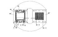
- a metal separator 120 having a pair of provided header portions 122a and 122b has been proposed (see Patent Document 1).
- a sealing material (not shown) for making the header portions 122a and 122b into a sealed space is disposed, and the oxidant gas and the fuel gas are allowed to flow through the corrugated flow path without leaking.
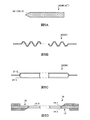
- the other groove for preventing the gas leakage is to seal the groove on the back of the gas channel 101 of the metal separator 100 with a sealing material 102.
- a sealing material 102 has been proposed (see Patent Document 2).
- the leak at the channel end of the gas channel is suppressed and mixing of the reaction gas is prevented.
- sealing material or a rubber sheet is tightly sealed inside the groove forming the flow path.
- the sealing state by the sealing material 102 (FIG. 7) or the rubber sheet 112 (FIG. 8) also changes according to the driving state of the fuel cell.
- the sealing property must be maintained even when the pressure difference between the sealed channel and another channel or outside air is maximum. Normally, even when a pressure difference of 150 kPa is generated, the amount of gas leakage is required to be 20 SCCM or less.
- the MEA seal member is extended (see 122 in FIG. 9), and the extended seal portion is fitted into the separator flow path, so that the reactant gas leaks at the end of the flow path of the metal manifold.
- a device to prevent this has been proposed (see Patent Document 4).
- This extension seal part becomes a boundary of the flow path group, and regulates the flow of fluid appropriately.
- this extended seal portion electrically insulates the separator and the electrode. For this reason, the contact portion between the extended seal and the electrode does not contribute to current passage, and as a whole, the contact resistance increases and the output voltage decreases. As a result, there arises a problem that the power generation efficiency of the fuel cell system as a whole decreases.
- the extended seal is not properly fitted into the flow path, that is, the positional deviation may occur.
- the present invention provides a fuel cell using a metal separator, which has a simple structure and does not require an excessive fastening force, and which can more reliably suppress the leakage of reaction gas. With the goal.
- the present invention relates to a fuel cell including the fuel unit cell shown below or a laminate thereof.
- a polymer electrolyte membrane and a frame body that holds a fuel electrode and an oxidation electrode sandwiching the polymer electrolyte membrane inside the frame; a flow path that is stacked on the fuel electrode and that supplies and discharges fuel gas
- a polymer electrolyte fuel cell comprising: an anode separator having; and a cathode separator having a flow path for supplying and discharging an oxidant gas, laminated on the oxidation electrode, The central portion of the anode separator and the cathode separator is opposed to the fuel electrode and the oxidation electrode, and grooves and ribs are alternately formed on the front and back, and has a corrugated cross section with a constant thickness, and a straight flow path.
- An outer peripheral portion of the anode separator and the cathode separator has a flat plate structure having a manifold hole; On both sides of the frame, A recess for turning back the flow path formed by the anode separator or the cathode separator is formed, A sealing material is disposed along the periphery of the fuel electrode or the oxidation electrode, and is in contact with the rib at the boundary between the central portion and the outer peripheral portion of the anode separator or the cathode separator, and regulates the flow of the fuel gas or the oxidant gas.
- the contact surfaces of the sealing material disposed along the periphery of the fuel electrode or the oxidation electrode and the rib at the boundary between the central portion and the outer peripheral portion of the anode separator or the cathode separator are respectively separated from the frame body to the anode separator or the cathode separator.
- a polymer electrolyte fuel cell that is inclined with respect to the stacking direction.
- a polymer electrolyte fuel cell configured by laminating a plurality of fuel cells according to [1], A spacer frame laminated between the fuel cells, further comprising a frame for flowing cooling water into a separator flow path between the fuel cells; On both surfaces of the spacer frame, a seal material is formed that contacts the ribs at the boundary between the central portion and the outer peripheral portion of the anode separator or cathode separator, and regulates the flow of cooling water, The contact surface between the sealing material formed on the spacer frame and the rib at the boundary between the central portion and the outer peripheral portion of the anode separator or cathode separator is in the stacking direction from the spacer frame to the anode separator or cathode separator, respectively.
- a polymer electrolyte fuel cell that is inclined with respect to the fuel cell.
- a polymer electrolyte fuel cell configured by stacking a plurality of the fuel unit cells according to [1], A spacer frame laminated between the fuel cells, further comprising a frame that does not allow cooling water to flow in the separator flow path between the fuel cells, On both surfaces of the spacer frame, a sealing material is formed in contact with the rib at the boundary between the central portion and the outer peripheral portion of the anode separator or cathode separator, The contact surface between the sealing material formed on the spacer frame and the rib at the boundary between the central portion and the outer peripheral portion of the anode separator or cathode separator is in the stacking direction from the spacer frame to the anode separator or cathode separator, respectively.
- a polymer electrolyte fuel cell that is inclined with respect to the fuel cell.
- a polymer electrolyte membrane and a frame body that holds the fuel electrode and the oxidation electrode sandwiching the polymer electrolyte membrane inside the frame; a flow path that is stacked on the fuel electrode and that supplies and discharges fuel gas
- a polymer electrolyte fuel cell comprising: an anode separator having; and a cathode separator having a flow path for supplying and discharging an oxidant gas, laminated on the oxidation electrode, The central portion of the anode separator and the cathode separator is opposed to the fuel electrode and the oxidation electrode, and grooves and ribs are alternately formed on the front and back, and has a corrugated cross section with a constant thickness, and a serpentine-shaped flow path.
- An outer peripheral portion of the anode separator and the cathode separator has a flat plate structure having a manifold hole;
- the both sides of the frame body are arranged along the periphery of the fuel electrode or the oxidation electrode, and are in contact with the ribs at the boundary between the central portion and the outer peripheral portion of the anode separator or the cathode separator, and the fuel gas or the oxidant gas Sealing material that regulates the flow is arranged,
- a polymer electrolyte fuel cell that is inclined with respect to the stacking direction.
- the polymer electrolyte fuel cell of the present invention even when a metal separator is used, if the laminate is fastened with a normal force, even if a large pressure difference (for example, 150 kPa) occurs, the amount of gas leakage is reduced. It can be maintained at 20 SCCM or less, and gas mixing can be suppressed. Further, positioning is easy when the MEA and the separator are stacked, and misalignment is less likely to occur.
- a large pressure difference for example, 150 kPa
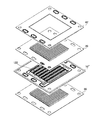
- FIG. 3 is a bird's-eye view of an MEA holding frame, an anode separator, a cathode separator, and a spacer frame of the fuel unit cell of Embodiment 1, and shows the state of the fuel unit cell before stacking. It is sectional drawing of the laminated body which laminated
- FIG. 5 is a bird's-eye view of an MEA holding frame, an anode separator, a cathode separator, and a spacer frame of the fuel cell of Embodiment 2, showing the state of the fuel cell before stacking.
- FIG. 5 is a bird's-eye view of an MEA holding frame, an anode separator, a cathode separator, and a spacer frame of the fuel cell of Embodiment 2, showing the state of the fuel cell before stacking.
- FIG. 7 is a bird's-eye view of an MEA holding frame, an anode separator, a cathode separator, and a spacer frame of the fuel cell of Embodiment 3, showing the state of the fuel cell before stacking.
- FIG. 7 is a bird's-eye view of an MEA holding frame, an anode separator, a cathode separator, and a spacer frame of the fuel cell of Embodiment 4, showing the state of the fuel cell before stacking.
- FIG. 4B shows contact surfaces of the anode separator and the spacer frame of FIG. 4A. 4B shows the contact surfaces of the MEA holding frame and the anode separator of FIG. 4A with each other.
- FIG. 4B shows the contact surfaces of the cathode separator and the spacer frame of FIG. 4A with each other. It is sectional drawing of the fuel cell of FIG. It is sectional drawing of the fuel cell of FIG. 5A is a cross section of the spacer frame A in FIG. 1; FIG. 5B is a cross section of the separator B in FIG. 1, FIG. 5C is a cross section of the separator C in FIG. It is a figure which shows the cross section of D of the MEA holding frame in. The state in which each member contained in it inclines with respect to the lamination direction is shown. It is a figure which shows the conventional metal separator. It is a figure which shows the conventional metal separator. It is a figure which shows the conventional metal separator. It is a figure which shows the conventional metal separator. It is a figure which shows the conventional metal separator.
- the fuel unit cell of the present invention includes: 1) a frame body that holds a polymer electrolyte membrane, and a fuel electrode and an oxidation electrode that sandwich the polymer electrolyte membrane within the frame; 2) laminated on the fuel electrode An anode separator having a flow path for supplying and discharging a fuel gas, and 3) a cathode separator having a flow path for supplying and discharging an oxidant gas stacked on the oxidation electrode, It is called “fuel cell”.
- the anode separator and cathode separator of the fuel cell of the present invention are preferably metal separators (also referred to as “metal separators”).
- the cross section of the metal separator has a corrugated shape, and grooves and ribs are alternately formed on the surface of the separator.
- the thickness of the metal separator is substantially constant, and the thickness of the corrugated cross section is also substantially constant. That is, grooves and ribs are alternately formed on the first surface of the metal separator; ribs and grooves are respectively formed on the back surface of the first surface at locations corresponding to the grooves and ribs.
- the metal separator can be produced by pressing a metal plate into a corrugated shape. Of the grooves and ribs formed in the separator, fluid (fuel gas or oxidizing gas, or cooling water) flows through the grooves. That is, the groove becomes a separator flow path.
- a flow path is formed in the central part of the anode separator and the cathode separator, that is, grooves and ribs are formed; the outer peripheral part is flat and has manifold holes, but no flow path is formed.
- the manifold hole is a hole constituting the manifold of the fuel cell, and is a hole through which fuel gas, oxidant gas or refrigerant (for example, cooling water) flows.
- the central part of the separator in which the flow path is formed is opposed to the electrode (fuel electrode or oxidation electrode) of the MEA held in the frame body described later, and has the same shape and the same area as the electrode surface. It is preferable.
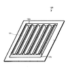
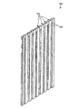
- the flow path formed in the central portion of the separator may be linear (see FIG. 1A and the like) or serpentine (see FIG. 4A and the like).
- a recess for turning the flow path needs to be formed in a frame body (described later) that holds the MEA (15 in FIG. 1A). See).
- the flow path formed in the central portion of the separator is serpentine-like, the flow path itself is folded back, so that a member (recessed portion) for folding the flow path to a frame body (described later) holding the MEA ) Is not necessary (see FIG. 4A). If the flow path is serpentine-like, it is possible to more reliably prevent gas leakage from outside the manifold hole to the flow path other than the connection port.
- the anode separator is stacked on the fuel electrode.
- a fuel gas flows through the flow path on the surface of the anode separator in contact with the fuel electrode.
- the cathode separator is laminated on the oxidation electrode. An oxidant gas is caused to flow through the flow path on the surface in contact with the oxidation electrode of the cathode separator.
- At least the ribs formed in the central part of the separator are preferably not protruding perpendicular to the separator surface but projecting in an inclined manner (FIG. 1 and FIG. 5B, see FIG. 5C).
- FIG. 1A “the end face in the longitudinal direction of the rib (see FIG. 5C)” and “the side surface of the rib (see FIG. 5B)” protrude from the separator surface in an inclined manner.
- at least the “end surface in the longitudinal direction of the rib” protrudes in an inclined manner. This is because gas leakage from the end of the flow path is suppressed without fastening with excessive force.
- the “side surface of the rib” is also inclined. This is because positioning when the separator is laminated on the MEA becomes easier.
- the rib at the boundary between the central portion and the outer peripheral portion of the separator is a sealing material (14 in FIGS. 1A and 1B) arranged around the electrode (oxidation electrode or fuel electrode) of a frame (described later) that holds the MEA. Or (see FIG. 5D).
- the sealing material disposed along the periphery of the MEA electrode is also inclined, and the inclination angle thereof corresponds to the inclination angle of the rib.
- the outer peripheral part (the area surrounding the central part) of the separator is flat and has a manifold hole. It is preferable that at least a fuel gas manifold hole and a cooling water manifold hole are formed in the outer peripheral portion of the anode separator; however, with or without an oxidant gas manifold hole (see FIG. 1A, etc.) (See FIG. 3) Good. In addition, it is preferable that at least an oxidant gas manifold hole and a cooling water manifold hole are formed in the outer peripheral portion of the cathode separator, but there is a fuel gas manifold hole (see FIG. 1A and the like). (See FIG. 3). As shown in FIG. 3, by omitting the manifold holes, it is possible to reduce the volume of the metal member having a larger specific gravity than the frame body or the MEA, and to reduce the weight of the fuel cell.
- the frame holding the MEA holds the polymer electrolyte membrane, the fuel electrode and the oxidation electrode sandwiching the polymer electrolyte membrane inside the frame, inside the frame.
- the polymer electrolyte membrane, the fuel electrode and the oxidation electrode are preferably laminated and integrated to form an MEA, and a frame body is preferably arranged on the outer periphery of the MEA to hold the MEA. .
- the inside of the frame body holding the MEA has the same shape and area as the central portion of the separator described above. That is, the electrodes (the fuel electrode and the oxidation electrode) exposed inside the frame are opposed to the central portion of the separator (the region where the flow path is formed).
- a sealing material is disposed on the inner periphery of the frame. That is, the sealing material is disposed along the outer periphery of the fuel electrode or the oxidation electrode held inside the frame. Therefore, the sealing material arranged on the inner periphery of the frame abuts on the rib at the boundary between the central portion and the outer peripheral portion of the separator.
- At least a part of the sealing material disposed on the inner periphery of the frame (that is, the sealing material disposed along the periphery of the electrode) is inclined.
- the sealing material that contacts the rib is also inclined in accordance with the inclination of the rib.
- the sealing material in contact with the “longitudinal end face” only needs to be inclined. If the “side surface” is inclined, the sealing material in contact with the “side surface of the rib” may be inclined.
- a “recess for turning the flow path” is formed in the frame holding the MEA (see 15 in FIG. 1A).
- the “recess for turning the flow path” is formed in a part of the frame corresponding to the flow path end of the linear flow path of the separator.
- the recess for turning back the flow path regulates the flow of fluid so that the fluid (reactive gas or cooling water) flowing through the flow path reaches the entire electrode surface in order.
- the “recess for turning the flow path” may be divided into a plurality of regions. In the portion corresponding to the flow path end of the flow path of the frame (see reference numeral 10) that holds the MEA shown in FIG. 1A, three recesses for turning the flow path are formed. Therefore, the fluid supplied from the supply manifold to the flow path reciprocates 3.5 and is discharged from the discharge manifold.
- the frame body that holds the MEA may be formed with a sealing material that seals the flow path from the outside or another flow path, as well as a sealing material that is disposed on the inner periphery of the frame (see reference numeral 13 in FIG. 1A). ). It is preferable that these sealing materials and the frame are integrally formed of the same material. By integrally molding, the deformation amount of the sealing material is reduced and the compression set can be reduced, so that the durability of the sealing material is improved.
- the rib at the boundary between the central portion and the outer peripheral portion of the separator of the fuel cell of the present invention is in contact with the sealing material disposed on the inner periphery of the frame body that holds the MEA.
- the fuel unit cell of the present invention is characterized in that the contact surface is not parallel to the stacking direction of the fuel unit cells but is inclined. More specifically, the normal line of the contact surface is directed to the separator in contact with the inner surface of the frame.
- the end surface in the longitudinal direction of the rib of the separator and the contact surface between the seal member of the frame body are inclined with respect to the stacking direction from the frame body to the separator.
- the degree of inclination is not strictly defined, but is preferably 30 to 45 ° with respect to the stacking direction.
- the contact surface is inclined with respect to the stacking direction of the fuel cells, the following effects can be obtained.
- the sealing material disposed on the inner periphery of the frame can more reliably seal the separator flow path. This is because by making the contact surface oblique, the fastening force is easily transmitted uniformly to the sealing material of the frame body and the rib of the separator over the entire contact surface of both. In particular, when the end surface of the rib in the longitudinal direction and the contact surface with the sealing material are inclined, the fluid is more reliably sealed.
- Misalignment in stacking the frame body holding the MEA and the separator is less likely to occur. This is because if they are laminated along the inclination, they can be easily arranged at appropriate positions.
- a fuel cell can be produced by laminating two or more fuel cell units of the present invention.
- a “spacer frame” may be disposed between the fuel cells.
- the spacer frame has cooling water manifold holes, and may be a frame for flowing cooling water from the cooling water manifold to the separator flow path between the cells (see FIG. 1A). 2) It may be a frame that does not allow cooling water to flow through the flow path between the cells (see FIG. 2).
- the spacer frame for flowing the cooling water has a communication path for guiding the cooling water from the cooling water manifold to the separator flow path formed on the surface not in contact with the electrode surface.
- the spacer frame that does not flow cooling water through the flow path does not have a communication path between the cooling water manifold and the flow path.
- a seal material is disposed on the inner periphery of the frame, and the seal material is in contact with a rib at the boundary between the central portion and the outer periphery of the separator. It is preferable that the sealing material and the frame body are the same material and are integrally formed.
- the rib at the boundary between the central portion and the outer peripheral portion of the separator (at least the end surface in the longitudinal direction of the linear rib) is not perpendicular to the plane of the separator but protrudes in an inclined manner. Therefore, it is preferable that the sealing material disposed on the inner periphery of the spacer frame is also inclined in accordance with the rib at the boundary between the central portion and the outer periphery of the separator. More specifically, the contact surface between the seal material of the spacer frame and the rib at the boundary between the central portion and the outer peripheral portion of the separator is inclined with respect to the stacking direction; It is preferable that it is suitable for the separator which is, and it is suitable for the inner side of the spacer frame.
- the inclination angle with respect to the stacking direction is preferably about 30 ° to 45 °.
- the anode separator is laminated on one side of the spacer frame, and the cathode separator is laminated on the other side. Therefore, it is preferable that the sealing material disposed on the inner periphery of the spacer frame is V-shaped (see FIG. 1A, FIG. 5A, etc.). By making the sealing material V-shaped, the contact surfaces with the ribs of both the anode separator and the cathode separator can be inclined.
- the spacer frame disposed between the single cells may be a frame for allowing cooling water to flow through the separator flow path between the single cells, or may be a frame that does not flow. May be.
- a spacer frame for flowing cooling water may be disposed for each single fuel cell, or may be disposed for every two or more fuel cells.
- the spacer frame for flowing cooling water through the separator channel When the flow path formed in the central part of the separator is linear, the spacer frame for flowing the cooling water into the separator flow path between the single cells has a dent for returning the cooling water flowing through the flow path. (See reference numeral 41 in FIG. 1A). It is preferable to restrict the flow of the dent for turning back the cooling water so that the cooling water spreads over the entire surface in order. Therefore, as shown in FIG. 1A, the spacer frame is formed with a plurality of dents for folding.
- spacer frame seal material (see reference numerals 42-1 and 42-2 in FIG. 1A) and the ribs of the separator are in contact with each other at an angle, so that there is no positional deviation in the stacking of the spacer frame and the separator. It becomes difficult to occur.
- the spacer frame that does not flow the cooling water into the separator flow path between the single cells is a rib (the end face in the longitudinal direction of the rib, It is preferable to have a sealing material in contact with the rib side surface). And if the contact surface of the sealing material of a spacer frame and the rib of a boundary inclines with respect to the lamination direction, a sealing effect will improve and positioning will become easy.
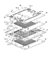
- FIG. 1A 1) a linear flow path is formed in the central portion of each separator, a folded portion of the flow path is formed in a frame that holds the MEA, and 2) it is disposed between the fuel cells.
- the state before stacking of a fuel cell in which a spacer frame for flowing cooling water is arranged in the separator channel is shown.
- FIG. 1A shows bird's-eye views of a frame body (MEA holding frame body) 10 that holds the MEA, an anode separator 20, a cathode separator 30, and a spacer frame body 40.
- 5A is a cross section of A of the spacer frame 40
- FIG. 5B is a cross section of B of the separators 20 and 30
- FIG. 5C is a cross section of C of the separators 20 and 30
- FIG. 5D is a cross section of D of the MEA holding frame 10. A cross section is shown.
- the MEA holding frame 10 can be produced by insert molding a polypropylene frame (length 220 mm ⁇ width 220 mm) around the MEA 11 (for example, length 150 mm ⁇ width 150 mm).
- a plurality of recesses 15 are formed in the frame of the MEA holding frame 10.
- the recess 15 serves as a region for turning back the reaction gas flowing through the flow path of the separator.
- the recess 15 is provided on both surfaces (the anode side and the cathode side) of the frame body 10 (the cathode side is not shown).
- the MEA holding frame 10 is disposed on the inner periphery of the frame (that is, disposed along the outer periphery of the MEA 11 held on the frame 10) (14-1, 14-2, 14-3). Including). Furthermore, it has the sealing material 13 which prevents the leak of the gas to the exterior.
- Each sealing material can be formed by molding two colors of fluoro rubber.
- the seal material 13 surrounds each of the manifold holes 16 to 18 (fuel gas manifold hole 16, cooling water manifold hole 17, oxidant gas manifold hole 18) and MEA 11 so that gas does not leak to the outside.
- the sealing material 13 and the sealing material 14 are provided on both surfaces (the anode side and the cathode side) of the frame body 10 (the anode side is not shown).
- the thickness (height from the MEA) of a part (14-1 and 14-3) of the sealing material 14 is the same as the height of the flow path (rib height) formed in the separators 20 and 30.
- another part of the sealing material 14 that is, the sealing material 14-2 formed in the recess 15 of the frame 10, and the communication path 16-1 with the fuel gas manifold hole 16 are provided.
- the thickness of the formed sealing material 14 and the sealing material 14 formed in the communication path (not shown) with the oxidant gas manifold hole 18 must be lower than the height of the flow path formed in the separator. is there. This is to ensure the flow of the reaction gas.
- the sealing material 14 (including 14-1, 14-2, and 14-3) is formed in an inclined manner, not parallel to the stacking direction of the members (10, 20, 30, and 40) (see FIG. 5D). It is tapered. Specifically, the sealing material 14 is inclined in a taper shape with respect to the stacking direction from the frame body 10 holding the MEA to each separator (the anode separator 20 or the cathode separator 30).
- the anode separator 20 and the cathode separator 30 are formed with a plurality of linear grooves and ribs at the center thereof.
- the end surface and the side surface of the formed rib are not perpendicular to the separator surface, but project at an angle of about 30 ° with respect to the vertical direction.
- the anode separator 20 is laminated on the fuel electrode side of the MEA holding frame body 10, and the end portion 21-1 and the side surface of the rib of the flow path formed on the anode side are in contact with the sealing material 14 of the MEA holding frame body 10.
- the cathode separator 30 is laminated on the oxidation electrode side of the MEA holding frame 10, and the end face 31-2 and the side surface of the rib of the flow path formed on the cathode side are sealed with the sealing material 14 (non- (Shown).
- the spacer frame 40 is formed with a sealing material 42 (including 42-1 and 42-2) on the inner periphery of a polypropylene frame (for example, 210 mm long ⁇ 210 mm wide), and further includes a fuel gas manifold hole 16 and an oxidation material. It is obtained by forming the sealant 44 surrounding the agent gas manifold hole 18 and the cavity of the frame of the spacer frame 40.
- the sealing material 44 prevents cooling water and reaction gas from leaking to the outside.
- Each sealing material is formed by molding two colors of fluoro rubber.
- the sealing material 42 disposed on the inner periphery of the spacer frame 40 abuts against the outer periphery of the rib (the end surface and side surface of the rib) formed in the central portion of the anode separator 20 and the cathode separator 30. Therefore, it is not parallel to the stacking direction of the members (10, 20, 30, 40) but is formed in a V shape (see FIG. 5A).
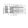
- FIG. 1B is a cross-sectional view of the vicinity of the end of the flow path (near the fuel gas manifold hole 16) of the laminate in which two unit cells shown in FIG. 1A are stacked.
- the outer frame of the anode separator 20, the cathode separator 30, and the spacer frame 40 is preferably smaller than the outer frame of the MEA holding frame 10. That is, it is preferable that the side surface of the fuel cell is covered with the outer peripheral surface of the MEA holding frame 10 so that the outer peripheral surfaces of the separators (20, 30) and the spacer frame 40 are not exposed.
- the end surface 21-2 of the rib on the cooling water side of the anode separator 20 contacts the sealing material 42-1 of the spacer frame 40.
- the end surface 31-2 of the cooling water side rib of the cathode side separator 30 is also in contact with the sealing material 42-1 of the spacer frame 40.
- the sealing material 42-1 is V-shaped.
- the fuel gas passes from the manifold hole 16 through the communication path 16-1 and enters the flow path of the anode separator 20 (the area surrounded by the MEA 11 and the side surface of the rib of the anode separator 20).
- the fuel gas that has reached the recess 15 of the MEA holding frame 10 changes its traveling direction by 180 ° and flows into the adjacent flow path. This operation is repeated to discharge from a discharge manifold hole (not shown).
- the oxidant gas enters the channel of the cathode separator 30 from the manifold hole 18 and is further discharged through the channel.
- the cooling water passes from the cooling water manifold hole 17 through the communication path 43 and enters the flow path of the cathode separator 30 (cooling water side) and the flow path of the anode separator 20 (cooling water side).
- the cooling water that has reached the dent 41 changes its traveling direction by 180 ° and flows into the adjacent flow path. This operation is repeated and discharged from the manifold hole 17 (discharge side).
- FIG. 10 shows a state where a stack of two or more fuel cells is sandwiched between current collector plates to form a fuel cell.
- Each fuel cell includes an MEA holding frame 10, an anode separator 20, a cathode separator 30, and a spacer frame 40.
- both ends of a stack of two or more fuel cell units are sandwiched between a current collector plate 90, an insulating plate 91, and an end plate 92 with piping, and fastened with bolts 93 and nuts 94 to form a fuel cell ( Fuel cell stack).
- FIG. 2 shows that 1) a linear flow path is formed in each separator, a folded portion of the flow path is formed in a frame body that holds the MEA, and 2) a single fuel cell disposed between the single fuel cells.
- stacking of the fuel cell which has the spacer frame which does not flow cooling water between batteries is shown.
- FIG. 2 is a bird's-eye view of the MEA holding frame 10, the anode separator 20, the cathode separator 30, and the spacer frame 40 '.
- the MEA holding frame 10, the anode separator 20, and the cathode separator 30 are the same as the fuel unit cell of the first embodiment (FIG. 1A).
- the unit cell shown in FIG. 1A has a spacer frame 40
- the unit cell shown in FIG. 2 has a spacer frame 40 '. That is, the cooling water of the fuel cell according to the second embodiment is not passed through the flow path between the stacked fuel cells. That is, the cooling water flows around the outer periphery of the fuel cell.
- the spacer frame 40 ′ has a seal 44 that surrounds the fuel gas manifold hole 16, the coolant manifold hole 17, and the oxidant gas manifold hole 18. Also, the sealing material 42 ′ disposed on the inner periphery of the spacer frame 40 ′ is different from the sealing material 42 (including 42-1 and 42-2) in FIG. 1 in the entire frame of the frame 40 ′. It is provided around the circumference. Therefore, the spacer frame 40 ′ does not have a connection path (see the communication path 43 in FIG. 1) between the cooling water manifold hole 17 and the cooling water flow path.
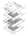
- FIG. 3 shows that 1) a linear flow path is formed in each separator, a folded portion of the flow path is formed in a frame body that holds the MEA, and 2) a flow path of the separator disposed between the fuel cells. 3) Each of the separators is provided with only a fuel gas manifold hole or an oxidant gas manifold hole, and a state before stacking of the fuel cells is shown. .
- FIG. 3 is a bird's-eye view of the MEA holding frame 10, the anode separator 20 ', the cathode separator 30', and the spacer frame 40.
- FIG. The MEA holding frame body 10 and the spacer frame body 40 are the same as the fuel unit cell of the first embodiment (FIG. 1A).
- the fuel cell shown in FIG. 3 is different from the fuel cell (FIG. 1) having the anode separator 20 and the cathode separator 30 in that the fuel cell has the anode separator 20 ′ and the cathode separator 30 ′. That is, the anode separator 20 ′ has the fuel gas manifold hole 16 and the coolant manifold hole 17, but does not have the oxidant gas manifold hole, and the portion where the oxidant gas manifold hole should be formed is deleted. Has been.
- the cathode separator 30 ′ has the oxidant gas manifold hole 18 and the cooling water manifold hole 17, but does not have the fuel gas manifold hole, and the portion where the fuel gas manifold hole should be formed is deleted. Yes.
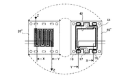
- FIG. 4A 1) a serpentine-shaped flow path is formed in the separator, the frame holding the MEA has no flow-folded portion of the flow path, and 2) the fuel cell is arranged between the fuel cells and cooled to the separator flow path
- positioned is shown.
- FIG. 4A is a bird's-eye view of the MEA holding frame 10 ′, the anode separator 20 ′′, the cathode separator 30 ′′, and the spacer frame 40 ′′.
- FIG. 4B shows the surface on the cooling water channel side of the anode separator 20 ′′ and the surface on the anode side of the spacer frame 40 ′′. That is, the surfaces of the anode separator 20 ′′ and the spacer frame 40 ′′ that contact each other are shown.
- the sealing material 42 of the spacer frame 40 ′′ contacts the ribs at the boundary between the central portion and the outer peripheral portion of the separator 20 ′′.
- An arrow Z indicates the direction in which the cooling water flows.
- FIG. 4C shows the MEA side surface of the anode separator 20 ′′ and the electrode surface of the MEA holding frame 10 ′. That is, the surfaces of the anode separator 20 ′′ and the MEA holding frame 10 ′ that are in contact with each other are shown.
- FIG. 4D shows a surface on the cooling water channel side of the cathode separator 30 ′′ and a surface on the cathode side of the spacer frame 40 ′′. That is, the surfaces of the cathode separator 30 ′′ and the spacer frame 40 ′′ that contact each other are shown.
- the sealing material 42 of the spacer frame 40 ′′ contacts the ribs at the boundary between the central portion and the outer peripheral portion of the cathode separator 30 ′′.
- 4E and 4F are cross-sectional views of a stack of two fuel single cells (a stack of MEA holding frame 10 ′, anode separator 20 ′′, cathode separator 30 ′′, spacer frame 40 ′′).
- . 4E is a cross-section along X in FIGS. 4B-D
- FIG. 4F is a cross-section along Y in FIGS. 4B-D.
- Example 1 An MEA holding frame, an anode separator, a cathode separator, and a spacer frame (FIG. 1) for flowing cooling water corresponding to the first embodiment were produced.
- the amount of catalytic metal contained in the obtained catalyst layer of each electrode was 0.3 mgc / m 2 , and the amount of perfluorosulfonic acid was 1.2 mgc / m 2 .
- the obtained cathode electrode and anode electrode had the same structure except for the catalyst material.
- Each of these electrodes was disposed on both sides of the central portion of the polymer electrolyte membrane having an area slightly larger than that.
- the polymer electrolyte membrane was a perfluorosulfonic acid thin film (thickness: 30 ⁇ m).
- a fluoro rubber sheet (thickness: 250 ⁇ m) cut out to a predetermined size (155 mm ⁇ 155 mm) is disposed on both sides of the exposed polymer electrolyte membrane with a part of the electrode sandwiched between them. Then, they were joined and integrated by hot pressing to obtain MEA.
- the MEA holding frame described in Embodiment 1 was produced using the MEA produced in this way.
- the groove depth (rib height) was about 1 mm. The press working was performed such that the rolling direction of the SUS316 plate material and the longitudinal direction of the wavy groove were parallel.
- the end face and side face of the rib formed in the center part of the SUS plate were not perpendicular to the surface of the SUS plate, but were inclined and protruded. Specifically, it was inclined 30 ° outward with respect to the vertical axis from the surface.
- a sealing material was disposed on the outer periphery of the MEA held by the MEA holding frame (that is, the inner periphery of the MEA holding frame).
- the disposed sealing material was in contact with a rib (an end surface or a side surface of the rib) at the boundary between the central portion and the outer peripheral portion of the separator. That is, the contact surface between the sealing material and the end face or side face of the rib of the separator was inclined by 30 ° with respect to the stacking direction.
- a single cell which is a laminate of a cathode separator, an MEA holding frame, an anode separator, and a spacer frame for flowing cooling water, was laminated in 50 cells. Further, the current collector plate made of a copper plate having a gold plating surface was sandwiched between the 50-cell laminates with a stainless steel end plate through an insulating plate made of polyphenylene sulfide, and both end plates were fastened with fastening rods. At this time, it adjusted with the pressure sensitive paper so that the fastening pressure per unit area of an electrode might be 100 N / cm ⁇ 2 >. The total fastening force, which is the sum of the compressive force applied to the electrode and the pressure applied to the seal, was 15 kN.
- the solid polymer fuel cell produced as described above was supplied with hydrogen and air at a hydrogen utilization rate of 70% and an oxygen utilization rate of 20%, and a performance test was conducted.
- the battery temperature was 75 ° C
- the dew point on the hydrogen side was 80 ° C
- the dew point on the air side was 75 ° C.
- a power output of 1050 W (35 V-30 A) was obtained.
- a low output about 50%
- hydrogen and air are used at a hydrogen utilization rate of 65% and an oxygen utilization rate of 15%. There was a need to supply.
- Example 1 A fuel cell was produced in the same manner as in Example 1 except that the separator shown in FIG. 7 was used as an anode separator and a cathode separator. However, the sealing material (reference numerals 14 and 42 in FIG. 1A) for the MEA holding frame and the spacer frame was omitted. In order to apply a fastening pressure of 100 N / cm 2 per electrode unit area and maintain the same hermeticity as in Example 1, it is necessary to closely attach a seal (reference numeral 102 in FIG. 7) to the channel groove of the separator. Yes, a total fastening force of 50 kN was required.
- Example 1 Although the separator flow path is linear, the amount of fuel gas and oxidant gas flowing into each flow path varies, and flooding is likely to occur in the flow path close to the outer periphery particularly during low-load operation. Therefore, as in Example 1, although a normal output was obtained with a hydrogen utilization rate of 70% and an oxygen utilization rate of 20%; to obtain a low output, a hydrogen utilization rate of 60% and an oxygen utilization rate of 12% It was necessary to flow air.
- Example 2 A fuel cell was produced in the same manner as in Example 1 except that the separator shown in FIG. 8 was used as an anode separator and a cathode separator (MEA holding frame and spacer frame sealing material (reference numeral 14 in FIG. 42) was omitted).
- the separator channel was serpentine.
- a seal (112 in FIG. 8) needs to be closely attached to the flow channel groove of the separator. A total fastening force of 20 kN was required.
- Example 3 A fuel cell was produced in the same manner as in Example 1 except that the separator and MEA holding frame shown in FIG. 9 were used.
- the sealing material 122 at the boundary portion of the flow path group of the MEA holding frame was an insulating member.
- a total fastening force of 12 kN was required.
- the contact resistance has increased, a predetermined voltage cannot be obtained, and when hydrogen and air are flowed at a hydrogen utilization rate of 70% and an oxygen utilization rate of 20%, an output of only 900 W (30V-30A) can be obtained. could not. Thus, the effectiveness of Example 1 was confirmed.
- Example 2 the fuel unit cell (referred to as “cooling unit cell”) including the spacer frame for flowing the cooling water described in the first embodiment, and the spacer frame body described in the second embodiment for not flowing the cooling water.
- the fuel cells (referred to as “non-cooled cells”) including these were alternately stacked, and both ends were cooled cells.
- the laminate was fastened with a fastening rod.
- Example 3 In Example 3, the MEA holding frame and separator described in Embodiment 3 (see FIG. 3) were used. In the anode separator, only the portion corresponding to the electrode, the circumference of the fuel gas manifold hole, and the circumference of the cooling water manifold hole are 5 mm, and the metal plate of the portion where the oxidant gas manifold hole is formed is omitted. Similarly, in the cathode separator, only the portion corresponding to the electrode, the circumference of the oxidant gas manifold hole, and the circumference of the cooling water manifold hole are 5 mm, and the metal plate of the portion where the fuel gas manifold hole is formed is omitted. Thereby, compared with Example 1, the weight of the separator alone was reduced by 15%, and the weight of the entire stack was reduced by 11%.
- stacked the cell was carried out similarly to Example 1, and was fastened.
- the fastening pressure at this time was 100 N / cm 2 per unit area of the electrode.
- the total fastening force including the compression force to the electrode and the pressure applied to the seal was 15 kN.
- Example 4 In Example 4, the MEA holding frame and the separator described in Embodiment 4 (see FIGS. 4A to F) were used.
- the flow path between the anode surface and the cooling water surface of the anode separator and the flow path between the cathode surface and the cooling water surface of the cathode separator are formed in a serpentine shape from the inlet to the outlet of the flow path.
- Example 4 Compared with the fuel unit cell of Example 1, the sealing performance was improved because the contact distance between the MEA holding frame body and the spacer member and the rib portion of the separator was longer. In particular, flooding is unlikely to occur at low loads, and in order to obtain a low output of 525 W (35V-15A) in Example 1, it was necessary to flow hydrogen and air at a hydrogen utilization rate of 65% and an oxygen utilization rate of 15%. In contrast, in Example 4, low output was obtained by flowing hydrogen and air at a hydrogen utilization rate of 67% and an oxygen utilization rate of 18%.
- Example 1 when the plate material of SUS316 was pressed into a serpentine shape, the metal plate was likely to break at the channel turn part. Therefore, the separator production yield in Example 1 was almost 100%, while the separator production yield in Example 4 was 85%.
- the polymer electrolyte fuel cell or fuel cell of the present invention uses a separator having a corrugated cross section, and does not require an excessive fastening force or increase in contact resistance. Regulates the flow of gas flowing through each other and reliably prevents mutual mixing.
- the polymer electrolyte fuel cell of the present invention is used in, for example, a portable power source, an electric vehicle power source, and a domestic cogeneration system.
Abstract
Description
前記アノードセパレータおよびカソードセパレータの中央部分は、前記燃料極および酸化極と相対し、表裏に溝とリブを交互に形成され、厚さが一定の波形断面を有し、かつ直線状の流路を形成されており;前記アノードセパレータおよびカソードセパレータの外周部分は、マニホールド穴を有する平板構造であり、
前記枠体の両面には、
前記アノードセパレータまたはカソードセパレータが形成する流路が折り返すための凹部が形成されており、
前記燃料極または酸化極の周囲に沿って配置され、前記アノードセパレータまたはカソードセパレータの中央部分と外周部分の境界のリブと接触して、燃料ガスまたは酸化剤ガスの流れを規制するシール材が配置され、
前記燃料極または酸化極の周囲に沿って配置されたシール材と、前記アノードセパレータまたはカソードセパレータの中央部分と外周部分の境界のリブとの接触面はそれぞれ、前記枠体からアノードセパレータまたはカソードセパレータへの積層方向に対して傾斜している、固体高分子型燃料単電池。
前記燃料単電池同士の間に積層されたスペーサ枠体であって、燃料単電池同士の間のセパレータ流路に冷却水を流すための枠体をさらに有し、
前記スペーサ枠体の両面には、前記アノードセパレータまたはカソードセパレータの中央部分と外周部分の境界のリブと接触し、冷却水の流れを規制するシール材が形成され、
前記スペーサ枠体に形成されたシール材と、前記アノードセパレータまたはカソードセパレータの中央部分と外周部分の境界のリブとの接触面はそれぞれ、前記スペーサ枠体からアノードセパレータまたはカソードセパレータへの積層方向に対して傾斜している、固体高分子型燃料電池。
前記燃料単電池同士の間に積層されたスペーサ枠体であって、燃料単電池同士の間のセパレータ流路に冷却水を流さない枠体をさらに有し、
前記スペーサ枠体の両面には、前記アノードセパレータまたはカソードセパレータの中央部分と外周部分の境界のリブと接触するシール材が形成され、
前記スペーサ枠体に形成されたシール材と、前記アノードセパレータまたはカソードセパレータの中央部分と外周部分の境界のリブとの接触面はそれぞれ、前記スペーサ枠体からアノードセパレータまたはカソードセパレータへの積層方向に対して傾斜している、固体高分子型燃料電池。
前記アノードセパレータおよびカソードセパレータの中央部分は、前記燃料極および酸化極と相対し、表裏に溝とリブを交互に形成され、厚さが一定の波形断面を有し、かつサーペンタイン状の流路を形成されており;前記アノードセパレータおよびカソードセパレータの外周部分は、マニホールド穴を有する平板構造であり、
前記枠体の両面には、前記燃料極または酸化極の周囲に沿って配置され、前記アノードセパレータまたはカソードセパレータの中央部分と外周部分の境界のリブと接触して、燃料ガスまたは酸化剤ガスの流れを規制するシール材が配置され、
前記燃料極または酸化極の周囲に沿って配置されたシール材と、前記アノードセパレータまたはカソードセパレータの中央部分と外周部分の境界のリブとの接触面はそれぞれ、前記枠体からアノードセパレータまたはカソードセパレータへの積層方向に対して傾斜している、固体高分子型燃料単電池。
本発明の燃料単電池は、1)高分子電解質膜と、高分子電解質膜を挟む燃料極および酸化極とを枠内に保持する枠体、2)燃料極に積層された、燃料ガスを供給および排出する流路を有するアノードセパレータ、3)酸化極に積層された、酸化剤ガスを供給および排出する流路を有するカソードセパレータとを有し、「固体高分子型燃料電池」などと称される。
本発明の燃料単電池のアノードセパレータおよびカソードセパレータは、金属製のセパレータ(「金属セパレータ」とも称する)であることが好ましい。金属セパレータの断面は波形形状を有し、セパレータの表面には溝とリブが交互に形成されている。金属セパレータの厚さはほぼ一定であり、波形断面の厚さもほぼ一定である。つまり、金属セパレータの第1面には、溝とリブが交互に形成されており;その溝とリブに対応する箇所の第1の面の裏面には、リブと溝がそれぞれ形成されている。金属セパレータは、金属板をプレス加工して波形形状とすることにより作製されうる。セパレータに形成された溝とリブのうち、溝に流体(燃料ガスまたは酸化ガス、あるいは冷却水)が流れる。つまり、溝がセパレータ流路となる。
MEAを保持する枠体は、枠内部に高分子電解質膜と、それを挟み込む燃料極と酸化極とを枠内部に保持する。高分子電解質膜ならびに燃料極および酸化極は、互いに積層されて一体化されることによりMEAとされていることが好ましく、MEAの外周に枠体は配置され、MEAを保持していることが好ましい。
枠の内周にはシール材が配置される。つまり、枠内部に保持された燃料極または酸化極の外周に沿ってシール材が配置される。そのため、枠の内周に配置されたシール材と、セパレータの中央部分と外周部分の境界のリブとが当接する。
前述の通り、本発明の燃料単電池のセパレータの中央部分と外周部分の境界のリブと、MEAを保持する枠体の枠内周に配置されたシール材とが接触している。本発明の燃料単電池は、この接触面が、燃料単電池の積層方向に対して、平行ではなく傾斜していることを特徴とする。より具体的に、この接触面の法線が、接触しているセパレータに向いており、かつ枠の内周に向かっている。
特に、セパレータのリブの長手方向の端面と、枠体のシール材との接触面が、枠体からセパレータへの積層方向に対して傾斜していることが好ましい。
1)燃料単電池を通常の締結力で締結すれば、枠体の枠内周に配置されたシール材が、セパレータ流路をより確実にシールすることができる。接触面を斜めにすることにより、締結力が、枠体のシール材とセパレータのリブとに両者の全接触面にわたって均一に伝わりやすくなるからである。特に、リブの長手方向の端面と、シール材との接触面が傾斜していると、流体のシールがより確実になる。
2)MEAを保持する枠体と、セパレータとの積層における位置ずれが生じにくくなる。傾斜に沿って積層すれば、適切な位置に配置しやすいからである。
本発明の燃料単電池の2以上を積層して、燃料電池を作製することができる。このとき、燃料単電池同士の間に「スペーサ枠体」を配置してもよい。スペーサ枠体は、冷却水マニホールド穴を有し、1)冷却水マニホールドから、単電池同士の間のセパレータ流路に、冷却水を流すための枠体であってもよいし(図1A参照)、2)単電池同士の間の流路に、冷却水を流さない枠体であってもよい(図2参照)。
スペーサ枠体は、枠の内周にシール材が配置されており、かつそのシール材がセパレータの中央部分と外周部分の境界のリブと接触する。シール材と枠体とは、同一の素材で、一体成形されていることが好ましい。
より具体的には、スペーサ枠体のシール材と、セパレータの中央部分と外周部分の境界のリブとの接触面が、積層方向に対して傾斜しており;接触面の法線が、接触しているセパレータに向いており、かつスペーサ枠体の内側に向いていることが好ましい。積層方向に対する傾斜角度は、約30°~45°が好ましい。
セパレータの中央部分に形成された流路が直線状であるときに、単電池同士の間のセパレータ流路に冷却水を流すためのスペーサ枠体は、流路を流れる冷却水が折り返すためのへこみ(図1Aにおける符号41参照)を有していることが好ましい。冷却水が折り返すためのへこみは、冷却水が面全体に順に行き渡るように流れを規制することが好ましい。そのため図1Aに示されるように、スペーサ枠体に、折り返すためのへこみが複数形成されている。その折り返すためのへこみの境界となるシール材と、セパレータのリブの長手方向の端面とが、積層方向に対して斜めに当接すると、シール効果が高まり、過剰な締結力が不要となる。
単電池同士の間のセパレータ流路に冷却水を流さないスペーサ枠体は、セパレータ流路の形状に係わらず、セパレータの中央部分と外周部分の境界全体のリブ(リブの長手方向の端面や、リブの側面を含む)と接触するシール材を有することが好ましい。そして、スペーサ枠体のシール材と、境界のリブとの接触面が、積層方向に対して傾斜していれば、シール効果が向上し、かつ位置決めが容易となる。
図1Aには、1)各セパレータの中央部分に直線状の流路が形成され、MEAを保持する枠体に流路の折り返し部が形成され、かつ2)燃料単電池同士の間に配置されたセパレータ流路に、冷却水を流すためのスペーサ枠体が配置された燃料単電池の、積層前の様子が示される。
図5Aはスペーサ枠体40のAの断面を、図5Bはセパレータ20および30のBの断面を、図5Cはセパレータ20および30のCの断面を、図5DはMEA保持枠体10のDの断面を示す。
図2は、1)各セパレータに直線状の流路が形成され、MEAを保持する枠体に流路の折り返し部が形成され、かつ2)燃料単電池同士の間に配置された、燃料単電池同士の間に冷却水を流さないスペーサ枠体を有する燃料単電池の積層前の様子が示される。
図3は、1)各セパレータに直線状の流路が形成され、MEAを保持する枠体に流路の折り返し部が形成され、2)燃料単電池同士の間に配置され、セパレータの流路に冷却水を流すためのスペーサ枠体が配置され、3)各セパレータには、燃料ガスマニホールド穴または酸化剤ガスマニホールド穴のいずれかだけが形成されている燃料単電池の積層前の様子を示す。
図4Aには、1)セパレータにサーペンタイン状の流路が形成され、MEAを保持する枠体に流路の折り返し部がなく、2)燃料単電池同士の間に配置され、セパレータ流路に冷却水を流すためのスペーサ枠体が配置される燃料単電池の積層前の様子が示される。
図4Cには、アノードセパレータ20’’のMEA側の面と、MEA保持枠体10’の電極面とが示される。つまり、アノードセパレータ20’’とMEA保持枠体10’の、互いに接触する面が示されている。MEA保持枠体10’のシール材14が、セパレータの中央部分と外周部分の境界のリブに接触する。
図4Dには、カソードセパレータ30’’の冷却水路側の面と、スペーサ枠体40’’のカソード側の面とが示される。つまり、カソードセパレータ30’’とスペーサ枠体40’’の、互いに接触する面が示されている。スペーサ枠体40’’のシール材42が、カソードセパレータ30’’の中央部分と外周部分の境界のリブに接触する。
実施の形態1に対応するMEA保持枠体、アノードセパレータ、カソードセパレータ、冷却水を流すためのスペーサ枠体(図1)を作製した。
アセチレンブラック系カーボン粉末に、平均粒度約30Åの白金粒子を25重量%担持して、カソード触媒を得た。また、アセチレンブラック系カーボン粉末に、平均粒度約30Åの白金-ルテニウム合金粒子を25重量%担持して、アノード触媒を得た。
これらの触媒粉末をイソプロピ-ルアルコールに分散させ、パーフルオロカーボンスルホン酸粉末のエチルアルコール分散液と混合してペースト状にした。得られたペーストのそれぞれを、スクリーン印刷法を用いて、厚さ250μmのカーボン不織布の一方の面に塗工して触媒層を形成した。得られた各々の電極の触媒層に含まれる触媒金属量を0.3mgc/m2、パーフルオロスルホン酸の量を1.2mgc/m2とした。得られたカソード電極とアノード電極とは、触媒材料以外は同一構造とした。
厚さ0.3mmのSUS316板(220mm×220mm)の中央部(155mm×155mm)をプレス加工して、5.6mmピッチ(溝幅2.8mm)の波状とした。溝の深さ(リブの高さ)は約1mmとした。プレス加工は、SUS316板材の圧延方向と波状溝の長手方向が平行となるようにして行った。
図7に示されたセパレータをアノードセパレータおよびカソードセパレータとすること以外は、実施例1と同様にして燃料電池を作製した。ただし、MEA保持枠体およびスペーサ枠体のシール材(図1Aにおける符号14や42)を省略した。電極単位面積あたり100N/cm2の締結圧を付与して、かつ実施例1と同様の気密性を維持するには、セパレータの流路溝にシール(図7の符号102)を密着させる必要があり、50kNの全締結力が必要であった。
図8に示されたセパレータをアノードセパレータおよびカソードセパレータとすること以外は、実施例1と同様にして燃料電池を作製した(MEA保持枠体およびスペーサ枠体のシール材(図1Aにおける符号14や42)を省略した)。セパレータ流路は、サーペンタイン状とした。電極単位面積あたり100N/cm2の締結圧を付与して、かつ実施例1と同様の気密性を維持するには、セパレータの流路溝にシール(図8の112)を密着させる必要があり、20kNの全締結力が必要であった。
図9に示されたセパレータとMEA保持枠体を用いること以外は、実施例1と同様にして燃料電池を作製した。MEA保持枠体の流路群の境界部分のシール材122は絶縁性部材とした。電極単位面積あたり100N/cm2の締結圧を付与して、かつ実施例1と同様の気密性を維持するには、12kNの全締結力が必要であった。しかしながら、接触抵抗が増大したため所定の電圧を得ることができず、水素利用率70%、酸素利用率20%で水素と空気を流したときに、900W(30V-30A)の出力しか得ることができなかった。
このように、実施例1の有効性が確認された。
実施例2では、実施の形態1で説明した冷却水を流すスペーサ枠体を含む燃料単電池(「冷却単電池」と称する)と、実施の形態2で説明した冷却水を流さないスペーサ枠体を含む燃料単電池(「非冷却単電池」と称する)とを交互に積層し、両端は冷却単電池とした。実施例1と同様にして、積層体を締結ロッドで締結した。
実施例3では、実施の形態3(図3参照)で説明したMEA保持枠体とセパレータを用いた。
アノードセパレータは、電極に対応する部分と、燃料ガスマニホールド穴の周囲5mmと、冷却水マニホールド穴の周囲5mmだけとして、酸化剤ガスマニホールド穴が形成される部分の金属板を省略した。同様に、カソードセパレータは、電極に対応する部分と、酸化剤ガスマニホールド穴の周囲5mmと、冷却水マニホールド穴の周囲5mmだけとして、燃料ガスマニホールド穴が形成される部分の金属板を省略した。
それにより、実施例1と比較して、セパレータ単体の重量が15%軽減され、積層スタック全体の重量が11%軽減された。
実施例4では、実施の形態4(図4A~Fを参照)で説明したMEA保持枠体とセパレータを用いた。アノードセパレータのアノード面と冷却水面の流路、およびカソードセパレータのカソード面と冷却水面の流路は、流路の入口から出口まで、サーペンタイン状に形成されている。
11 MEA
13 シール材
14-1,14-2,14-3 枠の内周に配置されたシール材
15 折り返すための凹部
16 燃料ガスマニホールド穴
16-1 連絡路
17 冷却水マニホールド穴
18 酸化剤ガスマニホールド穴
20,20’,20’’ アノードセパレータ
21-1,21-2 リブの長手方向の端面
30,30’,30’’ カソードセパレータ
31-1,31-2 リブの長手方向の端面
40,40’,40’’ スペーサ枠体
41 折り返すためのへこみ
42,42’,42-1,42-2 枠の内周に配置されたシール材
43 連絡路
44 シール材
90 集電板
91 絶縁板
92 配管付端板
93 ボルト
94 ナット
100,110,120 金属セパレータ
101,111,121 セパレータ流路
102,112,122 シール材
Claims (9)
- 高分子電解質膜と、前記高分子電解質膜を挟む燃料極および酸化極とを枠内部に保持する枠体と;前記燃料極に積層された、燃料ガスを供給および排出する流路を有するアノードセパレータと;前記酸化極に積層された、酸化剤ガスを供給および排出する流路を有するカソードセパレータと、を含む固体高分子型燃料単電池であって、
前記アノードセパレータおよびカソードセパレータの中央部分は、前記燃料極および酸化極と相対し、表裏に溝とリブを交互に形成され、厚さが一定の波形断面を有し、かつ直線状の流路を形成されており;前記アノードセパレータおよびカソードセパレータの外周部分は、マニホールド穴を有する平板構造であり、
前記枠体の両面には、
前記アノードセパレータまたはカソードセパレータが形成する流路が折り返すための凹部が形成されており、
前記燃料極または酸化極の周囲に沿って配置され、前記アノードセパレータまたはカソードセパレータの中央部分と外周部分との境界のリブと接触して、燃料ガスまたは酸化剤ガスの流れを規制するシール材が配置され、
前記燃料極または酸化極の周囲に沿って配置されたシール材と、前記アノードセパレータまたはカソードセパレータの中央部分と外周部分の境界のリブとの接触面はそれぞれ、前記枠体からアノードセパレータまたはカソードセパレータへの積層方向に対して傾斜している、固体高分子型燃料単電池。 - 前記燃料極または酸化極の周囲に沿って配置されたシール材と、前記アノードセパレータまたはカソードセパレータの中央部分と外周部分の境界のリブとの接触面の法線は、接触しているセパレータに向いており、かつ枠体内側に向いている、請求項1に記載の固体高分子型燃料単電池。
- 前記アノードセパレータおよびカソードセパレータは、金属製セパレータである、請求項1に記載の固体高分子型燃料単電池。
- 請求項1に記載の燃料単電池の複数個を積層して構成される固体高分子型燃料電池。
- 請求項1に記載の燃料単電池の複数個を積層して構成される固体高分子型燃料電池であって、
前記燃料単電池同士の間に積層されたスペーサ枠体であって、燃料単電池同士の間の前記セパレータ流路に冷却水を流すための枠体をさらに有し、
前記スペーサ枠体の両面には、前記アノードセパレータまたはカソードセパレータの中央部分と外周部分の境界のリブと接触し、冷却水の流れを規制するシール材が形成され、
前記スペーサ枠体に形成されたシール材と、前記アノードセパレータまたはカソードセパレータの中央部分と外周部分の境界のリブとの接触面はそれぞれ、前記スペーサ枠体からアノードセパレータまたはカソードセパレータへの積層方向に対して傾斜している、固体高分子型燃料電池。 - 請求項1に記載の燃料単電池の複数個を積層して構成される固体高分子型燃料電池であって、
前記燃料単電池同士の間に積層されたスペーサ枠体であって、燃料単電池同士の間の前記セパレータ流路に冷却水を流さない枠体をさらに有し、
前記スペーサ枠体の両面には、前記アノードセパレータまたはカソードセパレータの中央部分と外周部分との境界のリブと接触するシール材が形成され、
前記スペーサ枠体に形成されたシール材と、前記アノードセパレータまたはカソードセパレータの中央部分と外周部分の境界のリブとの接触面はそれぞれ、前記スペーサ枠体からアノードセパレータまたはカソードセパレータへの積層方向に対して傾斜している、固体高分子型燃料電池。 - 前記アノードセパレータは、燃料ガスマニホールド穴と冷却水マニホールド穴を有し、かつ酸化剤ガスマニホールド穴を有さず、
前記カソードセパレータは、酸化剤ガスマニホールド穴と冷却水マニホールド穴を有し、かつ燃料ガスマニホールド穴を有さない、
請求項1に記載の固体高分子型燃料単電池。 - 高分子電解質膜と、前記高分子電解質膜を挟む燃料極および酸化極とを枠内部に保持する枠体と;前記燃料極に積層された、燃料ガスを供給および排出する流路を有するアノードセパレータと;前記酸化極に積層された、酸化剤ガスを供給および排出する流路を有するカソードセパレータと、を含む固体高分子型燃料単電池であって、
前記アノードセパレータおよびカソードセパレータの中央部分は、前記燃料極および酸化極と相対し、表裏に溝とリブを交互に形成され、厚さが一定の波形断面を有し、かつサーペンタイン状の流路を形成されており;前記アノードセパレータおよびカソードセパレータの外周部分は、マニホールド穴を有する平板構造であり、
前記枠体の両面には、前記燃料極または酸化極の周囲に沿って配置され、前記アノードセパレータまたはカソードセパレータの中央部分と外周部分の境界のリブと接触して、燃料ガスまたは酸化剤ガスの流れを規制するシール材が配置され、
前記燃料極または酸化極の周囲に沿って配置されたシール材と、前記アノードセパレータまたはカソードセパレータの中央部分と外周部分の境界のリブとの接触面はそれぞれ、前記枠体からアノードセパレータまたはカソードセパレータへの積層方向に対して傾斜している、固体高分子型燃料単電池。 - 前記燃料極または酸化極の周囲に沿って配置されたシール材と、前記アノードセパレータまたはカソードセパレータの中央部分と外周部分の境界のリブとの接触面の法線は、接触しているセパレータに向いており、かつ枠体内側に向いている、請求項8に記載の固体高分子型燃料単電池。
Priority Applications (4)
| Application Number | Priority Date | Filing Date | Title |
|---|---|---|---|
| US12/595,141 US20100196774A1 (en) | 2008-05-28 | 2009-04-10 | Fuel cell |
| JP2009536503A JP4418527B2 (ja) | 2008-05-28 | 2009-04-10 | 燃料電池 |
| CN200980000234A CN101689655A (zh) | 2008-05-28 | 2009-04-10 | 燃料电池 |
| EP09726426.1A EP2306567B1 (en) | 2008-05-28 | 2009-04-10 | Fuel cell |
Applications Claiming Priority (2)
| Application Number | Priority Date | Filing Date | Title |
|---|---|---|---|
| JP2008-140111 | 2008-05-28 | ||
| JP2008140111 | 2008-05-28 |
Publications (1)
| Publication Number | Publication Date |
|---|---|
| WO2009144871A1 true WO2009144871A1 (ja) | 2009-12-03 |
Family
ID=41376763
Family Applications (1)
| Application Number | Title | Priority Date | Filing Date |
|---|---|---|---|
| PCT/JP2009/001671 WO2009144871A1 (ja) | 2008-05-28 | 2009-04-10 | 燃料電池 |
Country Status (6)
| Country | Link |
|---|---|
| US (1) | US20100196774A1 (ja) |
| EP (1) | EP2306567B1 (ja) |
| JP (1) | JP4418527B2 (ja) |
| KR (1) | KR100949423B1 (ja) |
| CN (1) | CN101689655A (ja) |
| WO (1) | WO2009144871A1 (ja) |
Cited By (11)
| Publication number | Priority date | Publication date | Assignee | Title |
|---|---|---|---|---|
| JP2010218700A (ja) * | 2009-03-13 | 2010-09-30 | Toyota Motor Corp | 燃料電池セル |
| WO2010115605A1 (de) * | 2009-04-08 | 2010-10-14 | Daimler Ag | Brennstoffzelle, brennstoffzellenstapel und verfahren zum abdichten einer brennstoffzelle |
| WO2011087013A1 (ja) * | 2010-01-14 | 2011-07-21 | 本田技研工業株式会社 | 燃料電池 |
| JP2011233420A (ja) * | 2010-04-28 | 2011-11-17 | Panasonic Corp | 固体高分子形燃料電池スタック |
| US20120156584A1 (en) * | 2010-03-17 | 2012-06-21 | Nissan Motor Co., Ltd. | Fuel cell |
| WO2014174959A1 (ja) * | 2013-04-22 | 2014-10-30 | 日産自動車株式会社 | 燃料電池スタックのセル構造 |
| JP2018098041A (ja) * | 2016-12-13 | 2018-06-21 | トヨタ自動車株式会社 | 燃料電池スタック |
| JP2021500710A (ja) * | 2017-10-30 | 2021-01-07 | ロベルト・ボッシュ・ゲゼルシャフト・ミト・ベシュレンクテル・ハフツングRobert Bosch Gmbh | 電解槽および燃料電池におけるガス分配および流れ案内のためのガス分配プレート |
| CN113013438A (zh) * | 2021-01-25 | 2021-06-22 | 沈阳诚高科技股份有限公司 | 一种氢燃料电池 |
| US20210384539A1 (en) * | 2020-01-08 | 2021-12-09 | Panasonic Intellectual Properly Management Co., Ltd. | Compression apparatus |
| US11978933B2 (en) * | 2020-01-08 | 2024-05-07 | Panasonic Intellectual Property Management Co., Ltd. | Compression apparatus |
Families Citing this family (17)
| Publication number | Priority date | Publication date | Assignee | Title |
|---|---|---|---|---|
| KR101147199B1 (ko) * | 2010-07-22 | 2012-05-25 | 삼성에스디아이 주식회사 | 막-전극 어셈블리, 연료전지 스택, 및 막-전극 어셈블리의 제조 방법 |
| US9660276B2 (en) * | 2010-10-20 | 2017-05-23 | Honda Motor Co., Ltd. | Fuel cell including separator with outer ends placed inward of fluid passages formed in frame |
| US8802326B2 (en) * | 2010-11-23 | 2014-08-12 | GM Global Technology Operations LLC | Fuel cell separator plate |
| WO2012114681A1 (ja) * | 2011-02-22 | 2012-08-30 | パナソニック株式会社 | 燃料電池及びそれを備える燃料電池スタック |
| CN102738471A (zh) * | 2011-04-01 | 2012-10-17 | 扬光绿能股份有限公司 | 燃料电池单元 |
| JP5395840B2 (ja) * | 2011-04-07 | 2014-01-22 | 本田技研工業株式会社 | 燃料電池 |
| JP5096647B1 (ja) * | 2011-05-17 | 2012-12-12 | パナソニック株式会社 | 固体高分子型燃料電池 |
| JP6756294B2 (ja) * | 2017-04-10 | 2020-09-16 | トヨタ自動車株式会社 | 燃料電池スタックおよび燃料電池スタックの製造方法 |
| US11271221B2 (en) * | 2017-06-06 | 2022-03-08 | Morimura Sofc Technology Co.. Ltd. | Electrochemical reaction cell stack, interconnector-electrochemical reaction unit cell composite, and method for manufacturing electrochemical reaction cell stack |
| JP6499247B2 (ja) * | 2017-09-07 | 2019-04-10 | 本田技研工業株式会社 | 燃料電池用セパレータ及び燃料電池スタック |
| CN108054407B (zh) * | 2017-12-14 | 2018-12-18 | 周劲 | 一种燃料电池膜电极的密封结构 |
| US20190273268A1 (en) * | 2018-03-02 | 2019-09-05 | Honda Motor Co., Ltd. | Frame equipped membrane electrode assembly, method of producing the frame equipped membrane electrode assembly, and fuel cell |
| JP6874723B2 (ja) * | 2018-03-14 | 2021-05-19 | トヨタ自動車株式会社 | 燃料電池スタック |
| JP6874724B2 (ja) * | 2018-03-28 | 2021-05-19 | トヨタ自動車株式会社 | 燃料電池 |
| JP6750809B1 (ja) * | 2019-04-22 | 2020-09-02 | 三菱電機株式会社 | 冷却器 |
| JP7136044B2 (ja) * | 2019-08-09 | 2022-09-13 | トヨタ自動車株式会社 | 燃料電池ユニット |
| CN112599812B (zh) * | 2020-12-14 | 2021-12-21 | 中国科学院大连化学物理研究所 | 一种新型膜电极密封组件及其连续制备封装设备 |
Citations (4)
| Publication number | Priority date | Publication date | Assignee | Title |
|---|---|---|---|---|
| WO2001059864A1 (fr) * | 2000-02-08 | 2001-08-16 | Matsushita Electric Industrial Co., Ltd. | Pile a combustible electrolytique polymerique |
| JP2002124275A (ja) * | 2000-10-17 | 2002-04-26 | Honda Motor Co Ltd | 燃料電池 |
| WO2007129642A1 (ja) * | 2006-05-01 | 2007-11-15 | Honda Motor Co., Ltd. | 燃料電池 |
| WO2008001755A1 (en) * | 2006-06-26 | 2008-01-03 | Panasonic Corporation | Solid polymer electrolyte fuel cell |
Family Cites Families (14)
| Publication number | Priority date | Publication date | Assignee | Title |
|---|---|---|---|---|
| CN1122322C (zh) * | 1998-04-17 | 2003-09-24 | 松下电器产业株式会社 | 固体高分子电解质型燃料电池及其制造方法 |
| KR100453597B1 (ko) * | 1998-06-30 | 2004-10-20 | 마쯔시다덴기산교 가부시키가이샤 | 고체고분자전해질형 연료전지 |
| JP3571696B2 (ja) * | 2001-01-30 | 2004-09-29 | 本田技研工業株式会社 | 燃料電池及び燃料電池スタック |
| EP1302996A3 (en) * | 2001-10-16 | 2006-04-19 | Matsushita Electric Industrial Co., Ltd. | Polymer electrolyte fuel cell |
| CA2477358C (en) * | 2003-08-22 | 2012-03-27 | Matsushita Electric Industrial Co., Ltd. | Polymer electrolyte fuel cell |
| CA2479325C (en) * | 2003-08-28 | 2010-08-10 | Honda Motor Co., Ltd. | Fuel cell having closure seal |
| JP4224439B2 (ja) * | 2003-08-28 | 2009-02-12 | 本田技研工業株式会社 | 燃料電池 |
| EP1594182B1 (en) * | 2004-04-27 | 2008-01-02 | Matsushita Electric Industrial Co., Ltd. | Fuel cell system |
| JP4621970B2 (ja) * | 2004-07-29 | 2011-02-02 | 東海ゴム工業株式会社 | 固体高分子型燃料電池用セパレータおよびそれを用いた固体高分子型燃料電池用セル |
| KR20060019843A (ko) * | 2004-08-30 | 2006-03-06 | 삼성에스디아이 주식회사 | 연료 전지 시스템 및 그 스택 |
| JP4129289B2 (ja) * | 2005-11-25 | 2008-08-06 | 松下電器産業株式会社 | 固体高分子型燃料電池 |
| JP5077620B2 (ja) * | 2005-12-16 | 2012-11-21 | トヨタ自動車株式会社 | 燃料電池のセパレータ |
| US7541108B2 (en) * | 2006-04-21 | 2009-06-02 | Panasonic Corporation | Solid polymer fuel cell |
| CN101346842B (zh) * | 2006-06-21 | 2012-04-18 | 松下电器产业株式会社 | 燃料电池 |
-
2009
- 2009-04-10 JP JP2009536503A patent/JP4418527B2/ja active Active
- 2009-04-10 KR KR1020097020895A patent/KR100949423B1/ko active IP Right Grant
- 2009-04-10 US US12/595,141 patent/US20100196774A1/en not_active Abandoned
- 2009-04-10 WO PCT/JP2009/001671 patent/WO2009144871A1/ja active Application Filing
- 2009-04-10 CN CN200980000234A patent/CN101689655A/zh active Pending
- 2009-04-10 EP EP09726426.1A patent/EP2306567B1/en active Active
Patent Citations (4)
| Publication number | Priority date | Publication date | Assignee | Title |
|---|---|---|---|---|
| WO2001059864A1 (fr) * | 2000-02-08 | 2001-08-16 | Matsushita Electric Industrial Co., Ltd. | Pile a combustible electrolytique polymerique |
| JP2002124275A (ja) * | 2000-10-17 | 2002-04-26 | Honda Motor Co Ltd | 燃料電池 |
| WO2007129642A1 (ja) * | 2006-05-01 | 2007-11-15 | Honda Motor Co., Ltd. | 燃料電池 |
| WO2008001755A1 (en) * | 2006-06-26 | 2008-01-03 | Panasonic Corporation | Solid polymer electrolyte fuel cell |
Non-Patent Citations (1)
| Title |
|---|
| See also references of EP2306567A4 * |
Cited By (19)
| Publication number | Priority date | Publication date | Assignee | Title |
|---|---|---|---|---|
| JP2010218700A (ja) * | 2009-03-13 | 2010-09-30 | Toyota Motor Corp | 燃料電池セル |
| WO2010115605A1 (de) * | 2009-04-08 | 2010-10-14 | Daimler Ag | Brennstoffzelle, brennstoffzellenstapel und verfahren zum abdichten einer brennstoffzelle |
| JP2012523656A (ja) * | 2009-04-08 | 2012-10-04 | ダイムラー・アクチェンゲゼルシャフト | 燃料電池、燃料電池スタック及び燃料電池のシーリング方法 |
| JP5587347B2 (ja) * | 2010-01-14 | 2014-09-10 | 本田技研工業株式会社 | 燃料電池 |
| WO2011087013A1 (ja) * | 2010-01-14 | 2011-07-21 | 本田技研工業株式会社 | 燃料電池 |
| US9559376B2 (en) | 2010-01-14 | 2017-01-31 | Honda Motor Co., Ltd. | Fuel cell with an electrolyte membrane and gas diffusion layers |
| US9190692B2 (en) * | 2010-03-17 | 2015-11-17 | Nissan Motor Co., Ltd. | Fuel cell |
| US20120156584A1 (en) * | 2010-03-17 | 2012-06-21 | Nissan Motor Co., Ltd. | Fuel cell |
| US10033058B2 (en) * | 2010-03-17 | 2018-07-24 | Nissan Motor Co., Ltd. | Fuel cell |
| JP2011233420A (ja) * | 2010-04-28 | 2011-11-17 | Panasonic Corp | 固体高分子形燃料電池スタック |
| WO2014174959A1 (ja) * | 2013-04-22 | 2014-10-30 | 日産自動車株式会社 | 燃料電池スタックのセル構造 |
| JPWO2014174959A1 (ja) * | 2013-04-22 | 2017-02-23 | 日産自動車株式会社 | 燃料電池スタックのセル構造 |
| US10199663B2 (en) | 2013-04-22 | 2019-02-05 | Nissan Motor Co., Ltd. | Cell structure for fuel cell stack |
| JP2018098041A (ja) * | 2016-12-13 | 2018-06-21 | トヨタ自動車株式会社 | 燃料電池スタック |
| JP2021500710A (ja) * | 2017-10-30 | 2021-01-07 | ロベルト・ボッシュ・ゲゼルシャフト・ミト・ベシュレンクテル・ハフツングRobert Bosch Gmbh | 電解槽および燃料電池におけるガス分配および流れ案内のためのガス分配プレート |
| US11316175B2 (en) | 2017-10-30 | 2022-04-26 | Robert Bosch Gmbh | Gas distributor plate for gas distribution and flow guidance in electrolysers and fuel cells |
| US20210384539A1 (en) * | 2020-01-08 | 2021-12-09 | Panasonic Intellectual Properly Management Co., Ltd. | Compression apparatus |
| US11978933B2 (en) * | 2020-01-08 | 2024-05-07 | Panasonic Intellectual Property Management Co., Ltd. | Compression apparatus |
| CN113013438A (zh) * | 2021-01-25 | 2021-06-22 | 沈阳诚高科技股份有限公司 | 一种氢燃料电池 |
Also Published As
| Publication number | Publication date |
|---|---|
| KR100949423B1 (ko) | 2010-03-24 |
| EP2306567A1 (en) | 2011-04-06 |
| EP2306567A4 (en) | 2012-06-06 |
| JPWO2009144871A1 (ja) | 2011-10-06 |
| KR20100002253A (ko) | 2010-01-06 |
| US20100196774A1 (en) | 2010-08-05 |
| JP4418527B2 (ja) | 2010-02-17 |
| CN101689655A (zh) | 2010-03-31 |
| EP2306567B1 (en) | 2014-03-26 |
Similar Documents
| Publication | Publication Date | Title |
|---|---|---|
| JP4418527B2 (ja) | 燃料電池 | |
| US8999596B2 (en) | Fuel cell | |
| US8551671B2 (en) | Fuel cell fluid sealing structure | |
| US8962212B2 (en) | Unit cell module and gasket for polymer electrolyte fuel cell | |
| US8110316B2 (en) | Fuel cell | |
| US7759014B2 (en) | Fuel cell having a seal member | |
| US9225032B2 (en) | Fuel cell | |
| US9660276B2 (en) | Fuel cell including separator with outer ends placed inward of fluid passages formed in frame | |
| US9099693B2 (en) | Fuel cell and fuel cell separator | |
| US20150072265A1 (en) | Fuel cell | |
| JP2007329125A (ja) | 改善された燃料電池設計のためのシール支持用の拡散媒体 | |
| US20140227622A1 (en) | Fuel cell | |
| US8241816B2 (en) | Fuel cell separator | |
| US7846613B2 (en) | Fuel cell with separator having a ridge member | |
| US9065091B2 (en) | Fuel cell | |
| JP4214027B2 (ja) | 燃料電池 | |
| JP4109569B2 (ja) | 燃料電池 | |
| JP4848824B2 (ja) | 固体高分子型燃料電池 | |
| JP2006210212A (ja) | 高分子電解質型燃料電池 | |
| JP3496819B2 (ja) | 高分子電解質型燃料電池 | |
| JP4851478B2 (ja) | 燃料電池 | |
| JP2006269264A (ja) | 固体高分子電解質形燃料電池 | |
| JP2009009773A (ja) | 燃料電池 |
Legal Events
| Date | Code | Title | Description |
|---|---|---|---|
| WWE | Wipo information: entry into national phase |
Ref document number: 200980000234.3 Country of ref document: CN |
|
| WWE | Wipo information: entry into national phase |
Ref document number: 2009536503 Country of ref document: JP |
|
| WWE | Wipo information: entry into national phase |
Ref document number: 2009726426 Country of ref document: EP |
|
| ENP | Entry into the national phase |
Ref document number: 20097020895 Country of ref document: KR Kind code of ref document: A |
|
| WWE | Wipo information: entry into national phase |
Ref document number: 12595141 Country of ref document: US |
|
| 121 | Ep: the epo has been informed by wipo that ep was designated in this application |
Ref document number: 09726426 Country of ref document: EP Kind code of ref document: A1 |
|
| NENP | Non-entry into the national phase |
Ref country code: DE |