WO2009136527A1 - Machine de travail du type marche - Google Patents
Machine de travail du type marche Download PDFInfo
- Publication number
- WO2009136527A1 WO2009136527A1 PCT/JP2009/056955 JP2009056955W WO2009136527A1 WO 2009136527 A1 WO2009136527 A1 WO 2009136527A1 JP 2009056955 W JP2009056955 W JP 2009056955W WO 2009136527 A1 WO2009136527 A1 WO 2009136527A1
- Authority
- WO
- WIPO (PCT)
- Prior art keywords
- grip
- work machine
- handle
- walking
- gas cylinder
- Prior art date
Links
Images


Classifications
-
- B—PERFORMING OPERATIONS; TRANSPORTING
- B60—VEHICLES IN GENERAL
- B60K—ARRANGEMENT OR MOUNTING OF PROPULSION UNITS OR OF TRANSMISSIONS IN VEHICLES; ARRANGEMENT OR MOUNTING OF PLURAL DIVERSE PRIME-MOVERS IN VEHICLES; AUXILIARY DRIVES FOR VEHICLES; INSTRUMENTATION OR DASHBOARDS FOR VEHICLES; ARRANGEMENTS IN CONNECTION WITH COOLING, AIR INTAKE, GAS EXHAUST OR FUEL SUPPLY OF PROPULSION UNITS IN VEHICLES
- B60K15/00—Arrangement in connection with fuel supply of combustion engines or other fuel consuming energy converters, e.g. fuel cells; Mounting or construction of fuel tanks
- B60K15/03—Fuel tanks
- B60K15/063—Arrangement of tanks
- B60K15/067—Mounting of tanks
- B60K15/07—Mounting of tanks of gas tanks
-
- A—HUMAN NECESSITIES
- A01—AGRICULTURE; FORESTRY; ANIMAL HUSBANDRY; HUNTING; TRAPPING; FISHING
- A01B—SOIL WORKING IN AGRICULTURE OR FORESTRY; PARTS, DETAILS, OR ACCESSORIES OF AGRICULTURAL MACHINES OR IMPLEMENTS, IN GENERAL
- A01B33/00—Tilling implements with rotary driven tools, e.g. in combination with fertiliser distributors or seeders, with grubbing chains, with sloping axles, with driven discs
- A01B33/02—Tilling implements with rotary driven tools, e.g. in combination with fertiliser distributors or seeders, with grubbing chains, with sloping axles, with driven discs with tools on horizontal shaft transverse to direction of travel
- A01B33/028—Tilling implements with rotary driven tools, e.g. in combination with fertiliser distributors or seeders, with grubbing chains, with sloping axles, with driven discs with tools on horizontal shaft transverse to direction of travel of the walk-behind type
-
- A—HUMAN NECESSITIES
- A01—AGRICULTURE; FORESTRY; ANIMAL HUSBANDRY; HUNTING; TRAPPING; FISHING
- A01B—SOIL WORKING IN AGRICULTURE OR FORESTRY; PARTS, DETAILS, OR ACCESSORIES OF AGRICULTURAL MACHINES OR IMPLEMENTS, IN GENERAL
- A01B33/00—Tilling implements with rotary driven tools, e.g. in combination with fertiliser distributors or seeders, with grubbing chains, with sloping axles, with driven discs
- A01B33/16—Tilling implements with rotary driven tools, e.g. in combination with fertiliser distributors or seeders, with grubbing chains, with sloping axles, with driven discs with special additional arrangements
-
- F—MECHANICAL ENGINEERING; LIGHTING; HEATING; WEAPONS; BLASTING
- F17—STORING OR DISTRIBUTING GASES OR LIQUIDS
- F17C—VESSELS FOR CONTAINING OR STORING COMPRESSED, LIQUEFIED OR SOLIDIFIED GASES; FIXED-CAPACITY GAS-HOLDERS; FILLING VESSELS WITH, OR DISCHARGING FROM VESSELS, COMPRESSED, LIQUEFIED, OR SOLIDIFIED GASES
- F17C13/00—Details of vessels or of the filling or discharging of vessels
- F17C13/08—Mounting arrangements for vessels
- F17C13/084—Mounting arrangements for vessels for small-sized storage vessels, e.g. compressed gas cylinders or bottles, disposable gas vessels, vessels adapted for automotive use
- F17C13/085—Mounting arrangements for vessels for small-sized storage vessels, e.g. compressed gas cylinders or bottles, disposable gas vessels, vessels adapted for automotive use on wheels
-
- B—PERFORMING OPERATIONS; TRANSPORTING
- B60—VEHICLES IN GENERAL
- B60Y—INDEXING SCHEME RELATING TO ASPECTS CROSS-CUTTING VEHICLE TECHNOLOGY
- B60Y2200/00—Type of vehicle
- B60Y2200/40—Special vehicles
- B60Y2200/41—Construction vehicles, e.g. graders, excavators
-
- F—MECHANICAL ENGINEERING; LIGHTING; HEATING; WEAPONS; BLASTING
- F17—STORING OR DISTRIBUTING GASES OR LIQUIDS
- F17C—VESSELS FOR CONTAINING OR STORING COMPRESSED, LIQUEFIED OR SOLIDIFIED GASES; FIXED-CAPACITY GAS-HOLDERS; FILLING VESSELS WITH, OR DISCHARGING FROM VESSELS, COMPRESSED, LIQUEFIED, OR SOLIDIFIED GASES
- F17C2205/00—Vessel construction, in particular mounting arrangements, attachments or identifications means
- F17C2205/01—Mounting arrangements
- F17C2205/0103—Exterior arrangements
- F17C2205/0111—Boxes
-
- F—MECHANICAL ENGINEERING; LIGHTING; HEATING; WEAPONS; BLASTING
- F17—STORING OR DISTRIBUTING GASES OR LIQUIDS
- F17C—VESSELS FOR CONTAINING OR STORING COMPRESSED, LIQUEFIED OR SOLIDIFIED GASES; FIXED-CAPACITY GAS-HOLDERS; FILLING VESSELS WITH, OR DISCHARGING FROM VESSELS, COMPRESSED, LIQUEFIED, OR SOLIDIFIED GASES
- F17C2205/00—Vessel construction, in particular mounting arrangements, attachments or identifications means
- F17C2205/01—Mounting arrangements
- F17C2205/0153—Details of mounting arrangements
- F17C2205/0157—Details of mounting arrangements for transport
- F17C2205/0165—Details of mounting arrangements for transport with handgrip
-
- F—MECHANICAL ENGINEERING; LIGHTING; HEATING; WEAPONS; BLASTING
- F17—STORING OR DISTRIBUTING GASES OR LIQUIDS
- F17C—VESSELS FOR CONTAINING OR STORING COMPRESSED, LIQUEFIED OR SOLIDIFIED GASES; FIXED-CAPACITY GAS-HOLDERS; FILLING VESSELS WITH, OR DISCHARGING FROM VESSELS, COMPRESSED, LIQUEFIED, OR SOLIDIFIED GASES
- F17C2221/00—Handled fluid, in particular type of fluid
- F17C2221/03—Mixtures
- F17C2221/032—Hydrocarbons
- F17C2221/035—Propane butane, e.g. LPG, GPL
-
- F—MECHANICAL ENGINEERING; LIGHTING; HEATING; WEAPONS; BLASTING
- F17—STORING OR DISTRIBUTING GASES OR LIQUIDS
- F17C—VESSELS FOR CONTAINING OR STORING COMPRESSED, LIQUEFIED OR SOLIDIFIED GASES; FIXED-CAPACITY GAS-HOLDERS; FILLING VESSELS WITH, OR DISCHARGING FROM VESSELS, COMPRESSED, LIQUEFIED, OR SOLIDIFIED GASES
- F17C2223/00—Handled fluid before transfer, i.e. state of fluid when stored in the vessel or before transfer from the vessel
- F17C2223/01—Handled fluid before transfer, i.e. state of fluid when stored in the vessel or before transfer from the vessel characterised by the phase
- F17C2223/0146—Two-phase
- F17C2223/0153—Liquefied gas, e.g. LPG, GPL
-
- F—MECHANICAL ENGINEERING; LIGHTING; HEATING; WEAPONS; BLASTING
- F17—STORING OR DISTRIBUTING GASES OR LIQUIDS
- F17C—VESSELS FOR CONTAINING OR STORING COMPRESSED, LIQUEFIED OR SOLIDIFIED GASES; FIXED-CAPACITY GAS-HOLDERS; FILLING VESSELS WITH, OR DISCHARGING FROM VESSELS, COMPRESSED, LIQUEFIED, OR SOLIDIFIED GASES
- F17C2223/00—Handled fluid before transfer, i.e. state of fluid when stored in the vessel or before transfer from the vessel
- F17C2223/03—Handled fluid before transfer, i.e. state of fluid when stored in the vessel or before transfer from the vessel characterised by the pressure level
- F17C2223/033—Small pressure, e.g. for liquefied gas
-
- F—MECHANICAL ENGINEERING; LIGHTING; HEATING; WEAPONS; BLASTING
- F17—STORING OR DISTRIBUTING GASES OR LIQUIDS
- F17C—VESSELS FOR CONTAINING OR STORING COMPRESSED, LIQUEFIED OR SOLIDIFIED GASES; FIXED-CAPACITY GAS-HOLDERS; FILLING VESSELS WITH, OR DISCHARGING FROM VESSELS, COMPRESSED, LIQUEFIED, OR SOLIDIFIED GASES
- F17C2270/00—Applications
- F17C2270/07—Applications for household use
- F17C2270/0736—Capsules, e.g. CO2
Definitions
- the present invention relates to a walking type working machine in which a cassette gas cylinder is provided in a direction along a handle post, and a gas engine is driven by fuel of the cassette gas cylinder.
- Some walk-type work machines have a handle post raised upward from the rear of the work machine main body, and a carry handle extended upward from the upper part of the outer peripheral wall of the handle post.
- a gripping part of a carry handle that is lifted by a hand so that the walking work machine can be transported is known.
- a gas engine is mounted on the work machine body, a handle post is raised rearward and upward from the rear part of the work machine body, and a cylinder storage part is provided on the outer peripheral wall of the handle post.
- a gas engine-mounted work machine in which a cassette gas cylinder is stored in a storage unit is known as disclosed in Patent Document 2.
- the carry handle of Patent Document 1 is extended upward from the upper part of the outer peripheral wall of the handle post.
- the gas engine-equipped working machine of Patent Document 2 is provided with a cylinder storage portion at the upper part of the outer peripheral wall of the handle post.
- the carry handle and the cylinder housing are both provided on the upper part of the outer peripheral wall of the handle post.
- the present invention provides a walking work machine in which a cylinder post (cassette gas cylinder) and a carry handle can be provided on a handle post.
- the work implement is a work implement main body, a handle post that is inclined rearward and upward from a rear portion of the work implement main body, and a direction along a longitudinal direction of the handle post.
- a cassette gas cylinder provided on the handle post, a gas engine driven by fuel in the cassette gas cylinder, and a carry handle provided on the handle post and having a grip formed so as to surround the cassette gas cylinder.
- a walking work machine is provided.
- both the cylinder storage portion and the carry handle can be provided on the handle post. Furthermore, a carrying handle for transportation is formed so as to surround the cassette gas cylinder. Thereby, the cassette gas cylinder can be protected by the carry handle.
- a cylinder cover for holding the cassette gas cylinder is provided between the cassette gas cylinder and the carry handle so as to be freely opened and closed. Therefore, when the cylinder cover is opened, the cylinder cover can be brought into contact with the carry handle, and the opening amount of the cylinder cover can be suitably ensured.
- the cassette gas cylinder can be easily attached and detached, and the usability can be improved.
- the grip has left and right grip portions extending so as to gradually spread from the left and right side portions of the cassette gas cylinder toward the front of the work machine.
- the grip is provided with left and right grip portions. Then, the left and right grip portions were extended so as to gradually spread from the left and right side portions of the cassette gas cylinder toward the front of the work machine. Therefore, since the distance between the left grip part and the right grip part is relatively large, when two people standing on the left and right sides of the walking work machine grip the left and right grip parts, Interference with each other can be prevented.
- the grip has a central grip portion extending between front end portions of the left and right grip portions.
- a relatively large space between the front end portions of the left and right grip portions can be secured. This makes it possible to ensure a relatively large length of the central grip portion, making the central grip portion easier to grip (easier to lift), and improving the transportability when carrying a walking work machine by one person. Can be increased.
- FIG. 4 is an exploded perspective view showing a state where a cylinder storage part is removed from the handle post shown in FIG. 3.
- FIG. 5 is a plan view of the carry handle shown in FIG. 4. It is the figure which showed the example which hold
- a walking type tiller is exemplified as the walking type working machine, but the walking type working machine is not limited to this.
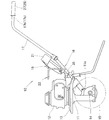
- a walking work machine 10 shown in FIG. 1 includes a gas engine 12 mounted on an upper end portion of a cultivator main body (work machine main body) 11, a fender 13 provided below the gas engine 12, and a lower part of the fender 13.
- the cylinder storage unit (cylinder holding unit) 18, the cassette gas cylinder 21 stored in the cylinder storage unit 18, and a carry handle 22 provided on the handle post 16 are provided.
- the gas engine 12 is driven by the fuel of the cassette gas cylinder 21, the power of the gas engine 12 is transmitted to the tilling shaft 14, and the tilling shaft 14 is rotated, so that a plurality of tilling claws 15
- the gas engine 12 is a gas engine that is driven by supplying fuel gas derived from the cassette gas cylinder 21.
- the handle post 16 is a cylindrical member extended so as to rise rearward and upward from the rear part of the work machine body.
- the operation handle 17 is supported on the upper end portion 16 a of the handle post 16 via the left and right support brackets 23.
- a cylinder storage portion 18 is provided in the upper half portion 25 of the handle post 16 in a direction along the upper half portion 25.
- a carrying handle 22 for transportation is provided on the substantially central peripheral wall portion 26 of the handle post 16.
- the operation handle 17 is a cylindrical member formed in a substantially U shape in front view as shown in FIG.
- the operation handle 17 has a lower end portion 17a attached to the upper end portion 16a of the handle post 16 via left and right support brackets 23, and left and right grips 27, 28 (FIG. 1) is provided.
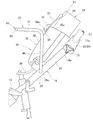
- the cylinder storage unit 18 includes a base 31 provided in an orientation along the upper half 25 of the handle post 16 and a cylinder cover 32 provided rotatably on the base 31.
- the base 31 includes a base support portion (not shown).
- the base support part detachably supports the base part of the cassette gas cylinder 21. By attaching the base part of the cassette gas cylinder 21 to the base support part, the cassette gas cylinder 21 is provided in a direction along the upper half 25 of the handle post 16.
- the cassette gas cylinder 21 is a commercially available gas cylinder in which the container main body 34 is filled with liquefied butane containing butane as a main component (hereinafter referred to as “liquid fuel gas”). As shown in FIG. 3, the cassette gas cylinder 21 has an injection nozzle protruding from the base portion of the container body 34. By pushing the injection nozzle toward the container main body 34, the liquid fuel gas stored in the container main body 34 is guided from the injection nozzle to the supply flow path 35.
- the cylinder cover 32 is arranged between the cassette gas cylinder 21 and the carry handle 22, and is in a closed position P1 (FIG. 2) where the cassette gas cylinder 21 can be pressed against the base 31, and an open position P2 where the cassette gas cylinder can be attached / removed (FIG. 6).
- the cover is rotatable.
- the cylinder cover 32 is arranged in the direction along the upper half portion 25 while being held at the closed position P1.
- the cylinder cover 32 includes a main cover 36 that is pivotally provided on the base 31, a sub-cover 37 that is pivotally provided at a distal end portion 36 a of the main cover 36, and a latch that is provided on the sub-cover 37. And claw 38.
- the main cover 36 is configured to be held at the closed position P1 by a spring member (not shown). By holding the main cover 36 at the closed position P ⁇ b> 1, the main cover 36 comes into contact with the cassette gas cylinder 21. Therefore, the cassette gas cylinder 21 can be pressed by the main cover 36.
- the sub cover 37 is rotatably supported by the front end portion 36a of the main cover 36 via a support pin 41, and can be held at the closed position P1 by a spring member (not shown). By holding the sub cover 37 at the closed position P ⁇ b> 1, the sub cover 37 comes into contact with the cassette gas cylinder 21. Therefore, the cassette gas cylinder 21 can be pressed by the sub cover 37.
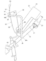
- the main cover 36 is opened to the open position P2 (FIG. 6) against the main spring member (not shown), and the sub cover 37 is opened to the open position P2 against the sub spring member (not shown).
- the latching claw 38 is latched to the carry handle 22 in a state where the handle is opened. Therefore, the main cover 36 and the sub cover 37 are held at the open position P2. Therefore, when the main cover 36 and the sub cover 37 are opened, the covers 36 and 37 are held in contact with the carry handle 22, and the opening amounts of the covers 36 and 37 can be suitably secured. .
- the cassette gas cylinder 21 can be easily attached and detached.
- An example of locking the locking claw 38 to the carry handle 22 will be described with reference to FIG.
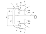
- the carry handle 22 is a member formed integrally by bending a tube (tubular body).
- left and right horizontal bases 43 and 44 are welded to the left and right wall portions 26 a and 26 b of the substantially central peripheral wall portion 26 of the handle post 16, respectively, and the grip 45 is positioned above the cylinder cover 32. is doing.
- the carry handle 22 is attached to the left and right horizontal bases 43 and 44 provided on the left and right wall portions 26a and 26b, the left leg 46 provided on the left horizontal base 43, and the right horizontal base 44, respectively.
- a right leg 47 provided and a grip 45 provided on the left and right legs 46, 47 are provided.
- the left horizontal base 43 extends horizontally from the left wall portion 26a toward the outside.
- the left horizontal base 43 is positioned below the cylinder storage portion 18, and the outer end 43 a is positioned outside the left side portion 18 a of the cylinder storage portion 18.
- the right horizontal base 44 extends horizontally outward from the right wall portion 26b coaxially with the left horizontal base 43.
- the right horizontal base 44 is positioned below the cylinder storage portion 18, and the outer end 44 a is positioned outside the right side portion 18 b of the cylinder storage portion 18.
- the left and right horizontal bases 43 and 44 are formed symmetrically.
- the left leg portion 46 extends upward from the outer end portion 43 a of the left horizontal base 43.
- the left leg portion 46 is located outside the left side portion 18 a in the cylinder storage portion 18.
- the right leg 47 extends upward from the outer end 44 a of the right horizontal base 44.
- the right leg portion 47 is located outside the right side portion 18 b in the cylinder storage portion 18.
- the left and right legs 46 and 47 are formed symmetrically.
- the grip 45 is provided in each upper end part 46a, 47a of the left and right leg parts 46, 47, and is formed in a substantially U shape.
- the grip 45 includes left and right grip portions 51 and 52 provided on the left and right leg portions 46 and 47, and a center grip portion 53 provided between the left and right grip portions 51 and 52, respectively.
- the left grip 51 extends horizontally at an inclination angle ⁇ so as to gradually incline outward from the upper end 46a of the left leg 46 toward the front of the work implement.
- the right grip 52 extends horizontally at an inclination angle ⁇ so as to gradually incline outward from the upper end 47a of the right leg 47 toward the front of the work implement. Therefore, the left and right grip portions 51 and 52 gradually spread from the upper end portions 46a and 47a of the left and right leg portions 46 and 47 (that is, the left and right side portions 21a and 21b side of the cassette gas cylinder 21) toward the front of the work machine. It extends horizontally and is symmetrical.
- the left and right grip portions 51 and 52 are positioned above the cylinder storage portion 18 and are formed to expand outward toward the front of the work machine. Accordingly, a relatively large distance L between the left grip portion 51 and the right grip portion 52 can be ensured. Therefore, when two people standing on the left and right sides of the walking work machine 10 grip the left and right grips 51 and 52, the two hands can be prevented from interfering with each other.
- the center grip 53 extends horizontally between the front end 51a of the left grip 51 and the front end 52a of the right grip 52 so as to be in the vehicle width direction.
- the central grip portion 53 is located above the cylinder storage portion 18.
- the center grip part 53 can secure a relatively large length, like the interval L, by forming the left and right grip parts 51 and 52 so as to expand forward.
- the central grip portion 53 can be easily grasped (can be easily lifted).
- the carry handle 22 is provided with the left and right horizontal bases 43 and 44 on the left and right wall portions 26 a and 26 b of the substantially central peripheral wall portion 26, respectively.
- the left and right leg portions 46 and 47 are disposed on the left and right sides of the cylinder storage portion 18, and the grip 45 is disposed above the cylinder storage portion 18.
- the carry handle 22 is formed so as to surround the cassette gas cylinder 21. In this way, by forming the carrying handle 22 for transportation so as to surround the cassette gas cylinder 21, it is possible to provide both the cylinder housing portion 18 and the carry handle 22 on the handle post 16.
- the carrying handle 22 for transportation is provided with a grip 45 that can be gripped. Thereby, by grasping the grip 45, the walking work machine 10 can be lifted and transported.
- the carrying handle 22 for transportation includes a cylinder storage unit 18 (that is, a cassette gas cylinder 21) including left and right horizontal bases 43 and 44, left and right legs 46 and 47, left and right grips 51 and 52, and a center grip 53. ).
- a cassette gas cylinder 21 including left and right horizontal bases 43 and 44, left and right legs 46 and 47, left and right grips 51 and 52, and a center grip 53.
- the main cover 36 is opened to the open position P2 against the main spring member (not shown), and the sub cover 37 is opened to the open position P2 against the sub spring member (not shown).
- the main cover 36 contacts the central grip portion 53 of the carry handle 22. Thereby, the opening amount of the main cover 36 and the sub cover 37 can be suitably ensured.
- the tip end portion 38 a of the locking claw 38 can be elastically deformed and locked to the central grip portion 53. Therefore, the main cover 36 and the sub cover 37 can be held at the open position P2. As a result, a state in which the main cover 36 and the sub cover 37 are suitably opened can be maintained, so that the cassette gas cylinder 21 can be easily attached and detached.
- the sub cover 37 When releasing the locking of the locking claw 38 to the central grip 53 by the tip 38a, the sub cover 37 is moved counterclockwise from the open position P2 with the support pin 41 as an axis. Then, the distal end portion 38 a of the locking claw 38 moves downward, and the distal end portion 38 a is separated from the central grip portion 53. Thereby, the main cover 36 can be moved in the closed position P1 direction by the spring force of the main spring member (not shown).
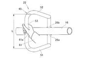
- FIG. 7A shows an example in which the walking type work machine 10 is carried by two people on the left and right sides
- FIG. 7B shows an example in which the walking type work machine 10 is carried by one person.
- the distance L between the left grip portion 51 and the right grip portion 52 is relatively large. Accordingly, when the transporter 61 standing on the left side of the walking type work machine 10 grips the left grip part 51 and the transporter 62 standing on the right side of the walking type work machine 10 grips the right grip part 52. The left and right transporters 61 and 62 do not interfere with each other's hands 61a and 62a.
- the left grip part 51 is inclined leftward and outward at an inclination angle ⁇ (FIG. 5) toward the front of the work machine.
- ⁇ inclination angle
- the left transporter 61 grips the left grip 51 with the right hand 61 a
- the upper 61 b of the right hand 61 a tilts forward according to the left grip 51. Therefore, the posture of the right hand 61a is maintained so that the left grip 51 can be easily lifted compared to the case where the upper 61b of the right hand 61a is oriented sideways (that is, the left grip 51 is disposed in parallel with the handle post 16). Can do.
- the left transporter 61 can easily lift the left grip 51 with the right hand 61a.
- the right grip part 52 is inclined at the inclination angle ⁇ (FIG. 5) toward the right outer side toward the front of the work machine.
- ⁇ inclination angle
- the right transporter 62 grips the right grip portion 52 with the left hand 62 a
- the upper 62 b of the left hand 62 a tilts forward according to the right grip portion 52. Therefore, the posture of the left hand 62a is maintained in a state in which the right grip portion 52 is easily lifted as compared with the case where the upper 62b of the left hand 62a is in the horizontal direction (that is, when the right grip portion 52 is arranged in parallel with the handle post 16). Can do.
- the right transporter 62 can easily lift the right grip 52 with the left hand 62a.
- the left and right grip portions 51 and 52 are inclined outward at an inclination angle ⁇ (FIG. 5) toward the front of the work machine, so that the left and right transporters 61 and 62 can be connected to the left and right grip portions 51 and 52.
- ⁇ inclination angle
- the left and right grip portions 51 and 52 can be expanded outward toward the front, thereby ensuring a relatively large length of the central grip portion 53.
- the left-side transporter 61 Can easily grip the center grip portion 53 with the right hand 61a (can be easily lifted). Thereby, the transportability at the time of carrying the walk type work machine 10 (FIG. 1) by one person can be improved.
- the carry handle 22, the cylinder cover 32, the grip 45, the left grip 51, the right grip 52, the center grip 53 and the like shown in the present embodiment are not limited to the illustrated shapes, and can be appropriately changed.
- the present invention is suitable for application to a walking work machine in which a cassette gas cylinder is provided in a direction along the handle post and the gas engine is driven by the fuel of the cassette gas cylinder.
- SYMBOLS 10 Walk type work machine, 11 ... Work machine main body, 11a ... Rear part of work machine main body, 12 ... Gas engine, 16 ... Handle post, 21 ... Cassette gas cylinder, 21a, 21b ... Right and left side part of cassette gas cylinder, 22 ... Carry handle, 32 ... cylinder cover, 45 ... grip, 51 ... left grip, 52 ... right grip, 53 ... center grip.
Abstract
Priority Applications (5)
| Application Number | Priority Date | Filing Date | Title |
|---|---|---|---|
| US12/991,306 US8191659B2 (en) | 2008-05-07 | 2009-04-03 | Walking-type working machine |
| EP09742652A EP2277366B1 (fr) | 2008-05-07 | 2009-04-03 | Machine de travail du type marche |
| CN200980115836.3A CN102014606B (zh) | 2008-05-07 | 2009-04-03 | 步行式作业机 |
| KR1020107025900A KR101184510B1 (ko) | 2008-05-07 | 2009-04-03 | 보행형 작업기 |
| ES09742652T ES2399316T3 (es) | 2008-05-07 | 2009-04-03 | Máquina de trabajo de tipo manejable caminando |
Applications Claiming Priority (2)
| Application Number | Priority Date | Filing Date | Title |
|---|---|---|---|
| JP2008121192A JP4951584B2 (ja) | 2008-05-07 | 2008-05-07 | 歩行型作業機 |
| JP2008-121192 | 2008-05-07 |
Publications (1)
| Publication Number | Publication Date |
|---|---|
| WO2009136527A1 true WO2009136527A1 (fr) | 2009-11-12 |
Family
ID=41264584
Family Applications (1)
| Application Number | Title | Priority Date | Filing Date |
|---|---|---|---|
| PCT/JP2009/056955 WO2009136527A1 (fr) | 2008-05-07 | 2009-04-03 | Machine de travail du type marche |
Country Status (7)
| Country | Link |
|---|---|
| US (1) | US8191659B2 (fr) |
| EP (1) | EP2277366B1 (fr) |
| JP (1) | JP4951584B2 (fr) |
| KR (1) | KR101184510B1 (fr) |
| CN (1) | CN102014606B (fr) |
| ES (1) | ES2399316T3 (fr) |
| WO (1) | WO2009136527A1 (fr) |
Families Citing this family (4)
| Publication number | Priority date | Publication date | Assignee | Title |
|---|---|---|---|---|
| JP4802237B2 (ja) * | 2008-11-26 | 2011-10-26 | 本田技研工業株式会社 | カセットガスボンベ取付構造 |
| US9167737B2 (en) * | 2013-05-22 | 2015-10-27 | Carts & Tools Technology, Inc. | Garden implement |
| KR200489768Y1 (ko) | 2018-06-18 | 2019-10-21 | 이범규 | 보행형 작업기용 동력전달장치 |
| KR102353595B1 (ko) | 2021-06-09 | 2022-01-20 | 이범규 | 직접 기어방식으로 동력을 전달하여 작업하는 보행형 작업기의 방향 전환장치 |
Citations (4)
| Publication number | Priority date | Publication date | Assignee | Title |
|---|---|---|---|---|
| JPH10131809A (ja) | 1996-10-30 | 1998-05-19 | Honda Motor Co Ltd | ガスエンジン及びガスエンジン作業機 |
| JPH11243701A (ja) * | 1998-03-04 | 1999-09-14 | Nikkari Co Ltd | 土壌管理機 |
| JP2002272202A (ja) | 2001-03-16 | 2002-09-24 | Iseki & Co Ltd | 車軸型ロータリ耕耘機 |
| JP2003225001A (ja) * | 2003-01-30 | 2003-08-12 | Iseki & Co Ltd | 歩行型耕耘装置 |
Family Cites Families (15)
| Publication number | Priority date | Publication date | Assignee | Title |
|---|---|---|---|---|
| BE666203A (fr) * | 1964-06-30 | |||
| US3452460A (en) * | 1966-10-31 | 1969-07-01 | Roper Corp | Impeller for rotary snow removal apparatus |
| US4255880A (en) * | 1979-06-25 | 1981-03-17 | Berkley And Company, Inc. | Portable rotary snow thrower |
| US5603173A (en) * | 1994-01-28 | 1997-02-18 | Ryobi Outdoor Products Inc. | Snow thrower |
| US5735064A (en) * | 1996-05-21 | 1998-04-07 | Holl; Trygve A. | Operational control mechanism |
| US5771582A (en) * | 1996-07-26 | 1998-06-30 | Wci Outdoor Products, Inc. | Apparatus for carrying spare line spool on flexible line trimmer |
| US5850882A (en) * | 1997-03-28 | 1998-12-22 | Link; Cletus H. | Garden power tool |
| JPH11170876A (ja) * | 1997-12-12 | 1999-06-29 | Yanmar Agricult Equip Co Ltd | 管理機 |
| JP2001322572A (ja) | 2000-05-17 | 2001-11-20 | Mitsubishi Agricult Mach Co Ltd | 歩行型移動農機 |
| CA2351863C (fr) * | 2000-07-12 | 2005-08-09 | Honda Giken Kogyo Kabushiki Kaisha | Machine chasse-neige |
| JP4556370B2 (ja) * | 2001-09-19 | 2010-10-06 | 井関農機株式会社 | 歩行型耕耘装置 |
| JP2007097442A (ja) | 2005-09-30 | 2007-04-19 | Iseki & Co Ltd | 歩行型耕耘機 |
| JP4700516B2 (ja) | 2006-02-21 | 2011-06-15 | 株式会社クボタ | 歩行型作業機 |
| CN1914984B (zh) * | 2006-09-01 | 2010-04-07 | 中国农业大学 | 新型燃料电池草坪机 |
| WO2010008773A2 (fr) * | 2008-06-23 | 2010-01-21 | Meydrive Llc | Chariot motorisé pour transport de fût |
-
2008
- 2008-05-07 JP JP2008121192A patent/JP4951584B2/ja active Active
-
2009
- 2009-04-03 KR KR1020107025900A patent/KR101184510B1/ko active IP Right Grant
- 2009-04-03 US US12/991,306 patent/US8191659B2/en active Active
- 2009-04-03 CN CN200980115836.3A patent/CN102014606B/zh not_active Expired - Fee Related
- 2009-04-03 WO PCT/JP2009/056955 patent/WO2009136527A1/fr active Application Filing
- 2009-04-03 ES ES09742652T patent/ES2399316T3/es active Active
- 2009-04-03 EP EP09742652A patent/EP2277366B1/fr not_active Not-in-force
Patent Citations (4)
| Publication number | Priority date | Publication date | Assignee | Title |
|---|---|---|---|---|
| JPH10131809A (ja) | 1996-10-30 | 1998-05-19 | Honda Motor Co Ltd | ガスエンジン及びガスエンジン作業機 |
| JPH11243701A (ja) * | 1998-03-04 | 1999-09-14 | Nikkari Co Ltd | 土壌管理機 |
| JP2002272202A (ja) | 2001-03-16 | 2002-09-24 | Iseki & Co Ltd | 車軸型ロータリ耕耘機 |
| JP2003225001A (ja) * | 2003-01-30 | 2003-08-12 | Iseki & Co Ltd | 歩行型耕耘装置 |
Non-Patent Citations (1)
| Title |
|---|
| See also references of EP2277366A4 |
Also Published As
| Publication number | Publication date |
|---|---|
| EP2277366A1 (fr) | 2011-01-26 |
| JP2009268401A (ja) | 2009-11-19 |
| CN102014606B (zh) | 2013-01-02 |
| JP4951584B2 (ja) | 2012-06-13 |
| ES2399316T3 (es) | 2013-03-27 |
| US8191659B2 (en) | 2012-06-05 |
| KR101184510B1 (ko) | 2012-09-19 |
| KR20110008249A (ko) | 2011-01-26 |
| CN102014606A (zh) | 2011-04-13 |
| US20110048818A1 (en) | 2011-03-03 |
| EP2277366B1 (fr) | 2012-11-28 |
| EP2277366A4 (fr) | 2011-06-08 |
Similar Documents
| Publication | Publication Date | Title |
|---|---|---|
| WO2009136527A1 (fr) | Machine de travail du type marche | |
| WO2016013398A1 (fr) | Tronçonneuse électrique | |
| JP6072745B2 (ja) | スクータ型車両 | |
| WO1984002638A1 (fr) | Poignee de guidage et de support pour bagages a roulettes | |
| JP2014088076A (ja) | 折畳み三輪車 | |
| JP2013021951A (ja) | 歩行型作業機 | |
| US20170072258A1 (en) | Hand held exercising device | |
| JP2009126301A (ja) | ガスエンジン搭載型作業機 | |
| JP2010100185A (ja) | 簡易噴霧車における操作ハンドル | |
| JP4403192B2 (ja) | ガスエンジン搭載型作業機のガスボンベ保持構造 | |
| JP4864859B2 (ja) | ガスエンジン搭載型作業機 | |
| JP2010024987A (ja) | 可搬式作業機 | |
| JP4484917B2 (ja) | 歩行型作業機のハンドル構造 | |
| JP2014221130A (ja) | 電気掃除機 | |
| JP5791880B2 (ja) | 歩行型耕耘機 | |
| JP7334999B2 (ja) | スティック型の清掃具 | |
| JP5857023B2 (ja) | キャリーバッグ | |
| JP6416075B2 (ja) | 歩行型作業機 | |
| JP6503197B2 (ja) | 電動車両 | |
| JP2008273488A (ja) | 歩行型作業車 | |
| JP7133365B2 (ja) | チェンソー | |
| JP4118534B2 (ja) | リーチフォークリフト用の操縦桿 | |
| JP2011067096A (ja) | 歩行型管理機 | |
| JP2010131359A (ja) | ベッド、及びロック補助体 | |
| JP2015027312A (ja) | 歩行型作業機 |
Legal Events
| Date | Code | Title | Description |
|---|---|---|---|
| WWE | Wipo information: entry into national phase |
Ref document number: 200980115836.3 Country of ref document: CN |
|
| 121 | Ep: the epo has been informed by wipo that ep was designated in this application |
Ref document number: 09742652 Country of ref document: EP Kind code of ref document: A1 |
|
| WWE | Wipo information: entry into national phase |
Ref document number: 12991306 Country of ref document: US |
|
| NENP | Non-entry into the national phase |
Ref country code: DE |
|
| ENP | Entry into the national phase |
Ref document number: 20107025900 Country of ref document: KR Kind code of ref document: A |
|
| WWE | Wipo information: entry into national phase |
Ref document number: 2009742652 Country of ref document: EP |