WO2009133752A1 - 駆動装置 - Google Patents
駆動装置 Download PDFInfo
- Publication number
- WO2009133752A1 WO2009133752A1 PCT/JP2009/057080 JP2009057080W WO2009133752A1 WO 2009133752 A1 WO2009133752 A1 WO 2009133752A1 JP 2009057080 W JP2009057080 W JP 2009057080W WO 2009133752 A1 WO2009133752 A1 WO 2009133752A1
- Authority
- WO
- WIPO (PCT)
- Prior art keywords
- rotating electrical
- electrical machine
- drive
- rotating
- input shaft
- Prior art date
- Legal status (The legal status is an assumption and is not a legal conclusion. Google has not performed a legal analysis and makes no representation as to the accuracy of the status listed.)
- Ceased
Links
Images


Classifications
-
- B—PERFORMING OPERATIONS; TRANSPORTING
- B60—VEHICLES IN GENERAL
- B60K—ARRANGEMENT OR MOUNTING OF PROPULSION UNITS OR OF TRANSMISSIONS IN VEHICLES; ARRANGEMENT OR MOUNTING OF PLURAL DIVERSE PRIME-MOVERS IN VEHICLES; AUXILIARY DRIVES FOR VEHICLES; INSTRUMENTATION OR DASHBOARDS FOR VEHICLES; ARRANGEMENTS IN CONNECTION WITH COOLING, AIR INTAKE, GAS EXHAUST OR FUEL SUPPLY OF PROPULSION UNITS IN VEHICLES
- B60K6/00—Arrangement or mounting of plural diverse prime-movers for mutual or common propulsion, e.g. hybrid propulsion systems comprising electric motors and internal combustion engines
- B60K6/20—Arrangement or mounting of plural diverse prime-movers for mutual or common propulsion, e.g. hybrid propulsion systems comprising electric motors and internal combustion engines the prime-movers consisting of electric motors and internal combustion engines, e.g. HEVs
- B60K6/22—Arrangement or mounting of plural diverse prime-movers for mutual or common propulsion, e.g. hybrid propulsion systems comprising electric motors and internal combustion engines the prime-movers consisting of electric motors and internal combustion engines, e.g. HEVs characterised by apparatus, components or means specially adapted for HEVs
- B60K6/36—Arrangement or mounting of plural diverse prime-movers for mutual or common propulsion, e.g. hybrid propulsion systems comprising electric motors and internal combustion engines the prime-movers consisting of electric motors and internal combustion engines, e.g. HEVs characterised by apparatus, components or means specially adapted for HEVs characterised by the transmission gearings
- B60K6/365—Arrangement or mounting of plural diverse prime-movers for mutual or common propulsion, e.g. hybrid propulsion systems comprising electric motors and internal combustion engines the prime-movers consisting of electric motors and internal combustion engines, e.g. HEVs characterised by apparatus, components or means specially adapted for HEVs characterised by the transmission gearings with the gears having orbital motion
-
- B—PERFORMING OPERATIONS; TRANSPORTING
- B60—VEHICLES IN GENERAL
- B60K—ARRANGEMENT OR MOUNTING OF PROPULSION UNITS OR OF TRANSMISSIONS IN VEHICLES; ARRANGEMENT OR MOUNTING OF PLURAL DIVERSE PRIME-MOVERS IN VEHICLES; AUXILIARY DRIVES FOR VEHICLES; INSTRUMENTATION OR DASHBOARDS FOR VEHICLES; ARRANGEMENTS IN CONNECTION WITH COOLING, AIR INTAKE, GAS EXHAUST OR FUEL SUPPLY OF PROPULSION UNITS IN VEHICLES
- B60K6/00—Arrangement or mounting of plural diverse prime-movers for mutual or common propulsion, e.g. hybrid propulsion systems comprising electric motors and internal combustion engines
- B60K6/20—Arrangement or mounting of plural diverse prime-movers for mutual or common propulsion, e.g. hybrid propulsion systems comprising electric motors and internal combustion engines the prime-movers consisting of electric motors and internal combustion engines, e.g. HEVs
- B60K6/22—Arrangement or mounting of plural diverse prime-movers for mutual or common propulsion, e.g. hybrid propulsion systems comprising electric motors and internal combustion engines the prime-movers consisting of electric motors and internal combustion engines, e.g. HEVs characterised by apparatus, components or means specially adapted for HEVs
- B60K6/40—Arrangement or mounting of plural diverse prime-movers for mutual or common propulsion, e.g. hybrid propulsion systems comprising electric motors and internal combustion engines the prime-movers consisting of electric motors and internal combustion engines, e.g. HEVs characterised by apparatus, components or means specially adapted for HEVs characterised by the assembly or relative disposition of components
- B60K6/405—Housings
-
- B—PERFORMING OPERATIONS; TRANSPORTING
- B60—VEHICLES IN GENERAL
- B60K—ARRANGEMENT OR MOUNTING OF PROPULSION UNITS OR OF TRANSMISSIONS IN VEHICLES; ARRANGEMENT OR MOUNTING OF PLURAL DIVERSE PRIME-MOVERS IN VEHICLES; AUXILIARY DRIVES FOR VEHICLES; INSTRUMENTATION OR DASHBOARDS FOR VEHICLES; ARRANGEMENTS IN CONNECTION WITH COOLING, AIR INTAKE, GAS EXHAUST OR FUEL SUPPLY OF PROPULSION UNITS IN VEHICLES
- B60K6/00—Arrangement or mounting of plural diverse prime-movers for mutual or common propulsion, e.g. hybrid propulsion systems comprising electric motors and internal combustion engines
- B60K6/20—Arrangement or mounting of plural diverse prime-movers for mutual or common propulsion, e.g. hybrid propulsion systems comprising electric motors and internal combustion engines the prime-movers consisting of electric motors and internal combustion engines, e.g. HEVs
- B60K6/42—Arrangement or mounting of plural diverse prime-movers for mutual or common propulsion, e.g. hybrid propulsion systems comprising electric motors and internal combustion engines the prime-movers consisting of electric motors and internal combustion engines, e.g. HEVs characterised by the architecture of the hybrid electric vehicle
- B60K6/44—Series-parallel type
- B60K6/445—Differential gearing distribution type
-
- B—PERFORMING OPERATIONS; TRANSPORTING
- B60—VEHICLES IN GENERAL
- B60K—ARRANGEMENT OR MOUNTING OF PROPULSION UNITS OR OF TRANSMISSIONS IN VEHICLES; ARRANGEMENT OR MOUNTING OF PLURAL DIVERSE PRIME-MOVERS IN VEHICLES; AUXILIARY DRIVES FOR VEHICLES; INSTRUMENTATION OR DASHBOARDS FOR VEHICLES; ARRANGEMENTS IN CONNECTION WITH COOLING, AIR INTAKE, GAS EXHAUST OR FUEL SUPPLY OF PROPULSION UNITS IN VEHICLES
- B60K1/00—Arrangement or mounting of electrical propulsion units
- B60K1/02—Arrangement or mounting of electrical propulsion units comprising more than one electric motor
-
- Y—GENERAL TAGGING OF NEW TECHNOLOGICAL DEVELOPMENTS; GENERAL TAGGING OF CROSS-SECTIONAL TECHNOLOGIES SPANNING OVER SEVERAL SECTIONS OF THE IPC; TECHNICAL SUBJECTS COVERED BY FORMER USPC CROSS-REFERENCE ART COLLECTIONS [XRACs] AND DIGESTS
- Y02—TECHNOLOGIES OR APPLICATIONS FOR MITIGATION OR ADAPTATION AGAINST CLIMATE CHANGE
- Y02T—CLIMATE CHANGE MITIGATION TECHNOLOGIES RELATED TO TRANSPORTATION
- Y02T10/00—Road transport of goods or passengers
- Y02T10/60—Other road transportation technologies with climate change mitigation effect
- Y02T10/62—Hybrid vehicles
Definitions
- the present invention includes an input shaft connected to the engine, a first rotating electrical machine, a second rotating electrical machine, a first rotating element connected to the first rotating electrical machine, and a second rotation connected to the input shaft.
- the present invention relates to a drive device including a differential gear device including an element and a third rotating element serving as an output rotating element, and a control device that controls the first rotating electric machine and the second rotating electric machine.
- Patent Document 1 discloses a configuration of a driving device in which an inverter case that accommodates a control device is integrally provided on an upper portion of a driving device case that accommodates two rotating electric machines, a differential gear device, and the like. ing.
- Patent Document 2 discloses the following drive device configuration.
- the drive device includes an input shaft connected to the engine, two rotating electrical machines, a differential gear device having three rotating elements connected to one of the rotating electrical machines, an input shaft, and an output rotating element, And a control device for controlling the electric machine.
- two rotating electrical machines, a differential gear device, and an input shaft are arranged coaxially, and control device components such as an inverter unit, a reactor, and a capacitor that constitute the control device
- positioned above a drive device is disclosed.
- control device since the control device is disposed at a position that overlaps with one of the rotating electrical machines in the axial direction, a capacitor and a reactor that are relatively large components among the control device components pass through the rotating shaft of the rotating electrical machine. By arranging them on the opposite sides with respect to the vertical plane, it is possible to efficiently store them in the drive unit case.
- JP 2004-343845 A (paragraph 0022, FIG. 1) JP 2007-124664 A (paragraphs 0072 to 0077, FIG. 5)
- This invention is made in view of said subject, and it aims at providing the drive device which can reduce the whole in size, after integrating a control apparatus.
- an input shaft connected to an engine, a first rotating electrical machine, a second rotating electrical machine, a first rotating element connected to the first rotating electrical machine, and the input shaft
- a differential gear device including a second rotating element connected to the first rotating element and a third rotating element serving as an output rotating element; and a control device that controls the first rotating electric machine and the second rotating electric machine.
- a characteristic configuration of the device is that the first rotating electrical machine and the differential gear device are arranged coaxially with the input shaft, and the first rotating electrical machine and the second rotating electrical machine are axially on different axes.
- the first component constituting the control device is lower than the first rotating electrical machine and at least a part of the first component in a plan view as viewed from vertically above Is arranged at a position overlapping with the first rotating electrical machine There to that point.
- the “rotary electric machine” is used as a concept including any of a motor (electric motor), a generator (generator), and a motor / generator that functions as both a motor and a generator as necessary. Moreover, in this specification, unless it distinguishes and uses especially, a rotary electric machine is used as a comprehensive concept which means one or both of a 1st rotary electric machine and a 2nd rotary electric machine.
- connection is used as a concept including not only direct connection between members but also indirect connection via one or more members between members.
- the entire drive device is compared with the case where they are disposed coaxially.
- the axial length of each rotating electrical machine can be increased while keeping the axial length as short. Therefore, the diameter of the rotating electrical machine can be reduced while the rotational driving force that can be output by the rotating electrical machine is the same as the conventional one, so that a space is created on the outer side in the radial direction of the rotating electrical machine by the reduced diameter. Can be made.
- the 1st component which comprises a control apparatus is the position below the 1st rotary electric machine among the said space, and the position which at least one part overlaps with the 1st rotary electric machine by the planar view seen from the perpendicular
- an input gear connected to the output rotation element is provided, and a drive output device that transmits the rotational driving force of the input gear to the output shaft is provided, and the rotation shaft of the input gear is lower than the input shaft. It is preferable that at least a part of the first component is arranged at a position overlapping the input gear in the vertical direction.
- overlapping with the input gear in the vertical direction means that the input gear is in a position within the height range occupied in the vertical direction.
- the output shaft that outputs the rotational driving force from the output rotating element of the differential gear device via the drive output device is disposed below the input shaft, A space is generated at a position below the first rotating electrical machine arranged coaxially with the input shaft and within a height range occupied by the input gear of the drive output device in the vertical direction. Therefore, by adopting the above configuration, the first component can be arranged using the space, and the space in the drive device can be effectively used. Therefore, the whole drive device can be reduced in size.
- the rotating shaft of the second rotating electrical machine is disposed above the input shaft and on the same side as the output shaft with respect to a vertical plane passing through the input shaft.
- the drive output device In the configuration in which the drive output device is integrated with the drive device, when the output shaft of the drive output device is disposed below the input shaft, the drive output device is above the drive output device and horizontally with the first rotating electrical machine. A space is generated at an overlapping position. Therefore, by adopting the above configuration, the second rotating electrical machine can be arranged using the space, and the space in the drive device can be effectively used. Therefore, the whole drive device can be reduced in size.
- the input shaft, the differential gear device, and the first rotating electrical machine are arranged in this order from the engine side.
- the drive output device When the drive device is mounted on the vehicle, the drive output device is preferably arranged as centrally as possible in the width direction of the vehicle. Considering the balance of the size of the engine and the drive device, the drive output device is as much as possible. It is preferable to arrange it close to the engine side.
- the drive output device when the drive output device is arranged on the input shaft side by adopting the above configuration and arranging the input shaft, the differential gear device, and the first rotating electrical machine in this order from the engine side, the drive output device And the first rotating electrical machine can be arranged so as not to overlap in the axial direction. Therefore, by disposing these relatively large parts in the axial direction, the entire drive device can be prevented from expanding in the radial direction, and the entire drive device can be downsized.
- At least a part of the second component different from the first component constituting the control device is arranged to overlap the first rotating electric machine in the vertical direction. It is.
- the first component is located at a position within the height range occupied by the first rotating electrical machine in the vertical direction in the space generated on the radially outer side of the rotating electrical machine by reducing the diameter of the rotating electrical machine. Since different second components are arranged, the space in the drive device can be used more effectively. Therefore, the whole drive device can be reduced in size.
- control device includes an inverter unit that performs conversion between DC power and AC power, and that the first component described so far is the inverter unit.
- the first chamber includes the first rotating electrical machine, the second rotating electrical machine, and the differential gear device, It is preferable that the control device is accommodated in the second chamber.
- lubricating oil for cooling and lubricating these components is supplied to the rotating electric machine and the differential gear device.
- the control device since the control device is configured to include electric parts such as an inverter unit, it requires electrical insulation and is preferably configured not to come into contact with lubricating oil or the like.
- the 1st chamber which accommodates a rotary electric machine and a differential gear apparatus and the 2nd chamber which accommodates a control apparatus are isolate
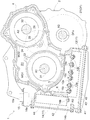
- FIG. 1 is a cross-sectional view in a plane perpendicular to the axial direction of a driving apparatus 1 according to an embodiment of the present invention.
- FIG. 2 is a bottom view of the drive device 1 according to the embodiment of the present invention as viewed from below the first axis A1
- FIG. 3 illustrates the drive device 1 according to the embodiment of the present invention on the first axis A1 side. It is the side view seen from the direction.
- FIG. 1 is a cross-sectional view in a plane perpendicular to the axial direction of a driving apparatus 1 according to an embodiment of the present invention.
- FIG. 2 is a bottom view of the drive device 1 according to the embodiment of the present invention as viewed from below the first axis A1
- FIG. 3 illustrates the drive device 1 according to the embodiment of the present invention on the first axis A1 side. It is the side view seen from the direction.
- FIG. 1 is a cross-sectional view in a plane perpendicular to the axial direction
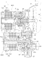
- FIG. 4 is a developed cross-sectional view of the drive device 1 according to the embodiment of the present invention.
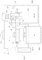
- FIG. 5 is a schematic diagram schematically showing the arrangement of each component when the drive device 1 is viewed from above
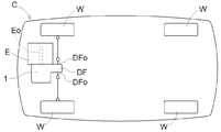
- FIG. 6 is a schematic diagram schematically showing the arrangement of the drive device 1 in the vehicle C. It is.
- the drive device 1 according to the present embodiment is arranged adjacent to the engine E placed horizontally on the vehicle C in the width direction of the vehicle C, and the axial direction of the output shaft Eo of the engine E Connected to The rotational driving force input from the output shaft Eo of the engine E (or the rotational driving force generated by the rotating electrical machine MG) is transmitted to the drive wheels W via the output shaft DFO of the drive output device DF of the drive device 1.
- the vehicle C can travel.
- the output shaft DFo of the drive output device DF is disposed behind the output shaft Eo of the engine E (the input shaft I of the drive device 1 (see FIG. 4)) in the longitudinal direction of the vehicle C. However, it may be disposed further forward than the output shaft Eo of the engine E (the input shaft I of the drive device 1).
- FIG. 1 shows a cross-sectional view in a plane perpendicular to the axial direction of the driving device 1 mounted on the vehicle C.
- the vertical direction in FIG. 1 will be described as the vertical direction.
- the drive device 1 includes two rotary electric machines MG, a first rotary electric machine MG1 and a second rotary electric machine MG2, and a drive output device DF.
- the first rotary electric machine MG1, the second rotary electric machine MG2, and the drive output device DF are arranged adjacent to each other in the radial direction, and are arranged so that a line connecting these axes forms a triangle.
- the shaft of the first rotating electrical machine MG1 (that is, the rotating shaft 31 of the rotor Ro1 of the first rotating electrical machine MG1 (see FIG. 4)) is the first axis A1
- the shaft of the second rotating electrical machine MG2 (that is, the second rotating electrical machine).
- the rotation axis 32 (see FIG. 4) of the rotor Ro2 of MG2 is a second axis A2
- the axis of the drive output device DF (the output shaft DFO of the drive output device DF) is the third axis A3.
- the first axis A1, the second axis A2, and the third axis A3 are arranged in parallel to each other.
- the “axial direction” means a direction parallel to the first axis A1, the second axis A2, and the third axis A3 (a direction perpendicular to the paper surface in FIG. 1). .
- the first rotating electrical machine MG1, the second rotating electrical machine MG2, and the drive output device DF are accommodated in the machine room R1 of the case 2.
- the drive device 1 includes a control device 11 that controls the first rotating electrical machine MG1 and the second rotating electrical machine MG2.
- the control device 11 includes at least an inverter unit 12 and a smoothing capacitor 14.
- the smoothing capacitor 14 smoothes the input power from a battery (not shown) as a power supply device and supplies the smoothed power to the inverter unit 12.
- the inverter unit 12 includes a bridge circuit configured using at least three sets of six switching elements, and performs conversion between DC power and AC power. These components constituting the control device 11 are electrically connected to each other via bus bars 16a and 16b, and the drive device 1 further includes a connector for electrical connection between the control device 11 and the battery. 15 is provided.
- the inverter unit 12 and the smoothing capacitor 14 are accommodated in the electric chamber R2 of the case 2.
- the case 2 includes an outer peripheral wall 4 and a partition wall 5, and the partition room 5 partitions the machine room R 1 and the electric room R 2.
- the machine room R1 and the electric room R2 are isolated from each other in a liquid-tight manner. Therefore, in the present embodiment, the machine room R1 and the electric room R2 correspond to the “first room” and the “second room” in the present invention, respectively.
- case 2 accommodates a machine room R1 in which the first rotating electrical machine MG1, the second rotating electrical machine MG2, and the like are accommodated, and an inverter unit 12 and a smoothing capacitor 14 that constitute the control device 11. And an electric room R2.
- a partition wall 5 partitions the machine room R1 and the electric room R2.
- the machine room R1 and the electric room R2 are partitioned by the partition wall 5 in the radial direction of the first rotary electric machine MG1, and the electric room R2 is radially outside the first rotary electric machine MG1 with respect to the machine room R1. Is formed.
- the outer peripheral wall 4 constituting the outer shape of the case 2 is approximately on each axis (first axis A1, second axis A2, and third axis A3) of the first rotary electric machine MG1, the second rotary electric machine MG2, and the drive output device DF. It is formed in a deformed cylindrical shape having parallel axes.
- the machine room R1 occupies most of the inside of the case 2, and the shape thereof follows the shape of the outer peripheral wall 4, and each axis of the first rotating electrical machine MG1, the second rotating electrical machine MG2, and the drive output device DF (first Axis A1, second axis A2 and third axis A3) have axes substantially parallel to each other, and have a modified cylindrical shape surrounding these outer shapes.
- the electric chamber R2 is formed so as to surround a part of the outer side in the radial direction of the machine room R1.
- the electric chamber R2 is positioned outside the partition wall 5 extending in an arc shape so as to follow the outer shape of the first rotating electrical machine MG1, and extends in the axial center circumferential direction of the first rotating electrical machine MG1.
- the electric chamber R2 is a space having a substantially L-shaped cross section when viewed from the axial direction (direction shown in FIG. 1).
- the inverter unit 12 is held in the electric chamber R2 in a substantially horizontal posture below the first rotating electrical machine MG1 in the vertical direction (vertical direction in FIG. 1).
- the smoothing capacitor 14 has a substantially vertical posture in the horizontal direction on the side of the first rotating electrical machine MG1, that is, on the opposite side to the drive output device DF with respect to the vertical plane passing through the rotation axis of the first rotating electrical machine MG1. Retained.
- the inverter unit 12 and the smoothing capacitor 14 are arranged such that their end portions are adjacent to each other.
- a connector 15 is provided for electrically connecting the inverter unit 12 and the smoothing capacitor 14 constituting the control device 11 to the battery.
- the connector 15 is supported so as to penetrate the case 2 from the electric chamber R2 and to be exposed to the outside of the case 2.
- the inverter unit 12 includes three terminals 13a connected to three-phase coils of the U-phase, V-phase, and W-phase of the first rotating electrical machine MG1, and the U of the second rotating electrical machine MG2.
- Three terminals 13b connected to a three-phase coil of phase, V phase, and W phase are provided.
- Each terminal 13a, 13b of the inverter unit 12 is connected to a coil of each phase of the first rotating electrical machine MG1 and the second rotating electrical machine MG2 via the bus bar 16c (see FIG. 3).
- the DC power supplied from the battery is converted into AC power via the inverter unit 12 and supplied to each phase coil of the first rotating electrical machine MG1 and the second rotating electrical machine MG2, or the first rotating electrical machine MG1.
- FIG. 3 shows only the connection between the inverter unit 12 and the first rotating electrical machine MG1 via the bus bar 16c, and the illustration of the connection between the inverter unit 12 and the second rotating electrical machine MG2 is omitted. Yes.
- the electric chamber R2 is formed with a first opening 41 opening downward and a second opening 42 opening laterally.
- the first opening 41 and the second opening 42 are formed in the outer peripheral wall 4 of the case 2.
- the first opening 41 is an opening for facilitating assembly, maintenance, and the like of the inverter unit 12 disposed below the first rotating electrical machine MG1 in the electric chamber R2.
- the planar shape of the first opening 41 is formed to be wider than the planar shape of the inverter unit 12 when viewed from below the case 2.
- the first opening 41 is covered with a first cover 43.
- the first cover 43 is attached to the outer peripheral wall 4 of the case 2 so as to cover the entire first opening 41.
- the first cover 43 includes fins 45 on both sides thereof. Since the first cover 43 installed facing the inverter unit 12 includes such fins 45, the heat generated by the inverter unit 12 can be efficiently released to the outside.
- the second opening 42 is an opening for facilitating the assembly and maintenance inspection of the smoothing capacitor 14 disposed on the side of the first rotating electrical machine MG1 in the electric chamber R2 to the case 2. Therefore, as shown in FIG. 3, the planar shape of the second opening 42 is formed to be wider than the planar shape of the smoothing capacitor 14 when viewed from the side of the case 2. Thereby, the smoothing capacitor 14 can be accommodated in the electric chamber R ⁇ b> 2 from the second opening 42 and fixed to the case 2.
- the second opening 42 is covered with a second cover 44.
- the second cover 44 is attached to the outer peripheral wall 4 of the case 2 so as to cover the entire second opening 42.
- the machine room R1 and the electric room R2 are physically partitioned by a partition wall 5 in the case 2 and are not shown, but the cover 3 (see FIG. 3 and FIG. 4) are in contact with each other to be isolated from each other in a liquid-tight manner.
- the input shaft I is connected to the output shaft Eo of the engine E.
- the engine E is an internal combustion engine driven by combustion of fuel, and for example, various known engines such as a gasoline engine and a diesel engine can be used.
- a damper 21 is interposed between the output shaft Eo of the engine E and the input shaft I of the drive device 1, and the damper 21 absorbs the torsional vibration between the two shafts while the rotational drive force of the engine E is absorbed.
- the signal is transmitted to the input shaft I and input into the driving device 1.
- the first rotating electrical machine MG1 includes a stator St1 fixed to the case 2 and a rotor Ro1 that is rotatably supported on the radial inner side of the stator St1.
- the stator St1 has a stator core Sc1 and a coil Co1 wound around the stator core Sc1.
- the rotating shaft 31 of the rotor Ro1 of the first rotating electrical machine MG1 is connected to rotate integrally with the sun gear s of the planetary gear device PG, and the first rotating electrical machine MG1 is mainly connected via the rotating shaft 31 of the rotor Ro1. It functions as a generator that generates electric power by the transmitted rotation.
- the first rotating electrical machine MG1 also functions as a motor depending on the relationship between the rotational direction and the direction of the rotational driving force.
- the second rotating electrical machine MG2 includes a stator St2 fixed to the case 2 and a rotor Ro2 that is rotatably supported on the radial inner side of the stator St2.
- the stator St2 has a stator core Sc2 and a coil Co2 wound around the stator core Sc2.
- the rotating shaft 32 of the rotor Ro2 of the second rotating electrical machine MG2 is connected to rotate integrally with the second rotating electrical machine output gear 23, and the second rotating electrical machine MG2 mainly generates rotation to generate torque. Functions as a motor. Torque generated by the rotation of the second rotating electrical machine MG2 is transmitted to the second rotating electrical machine output gear 23 via the rotating shaft 32 of the rotor Ro2.
- the second rotating electrical machine MG2 mainly functions as a motor, but the second rotating electrical machine MG2 also functions as a generator at the time of regenerative braking for deceleration of the vehicle C or the like.
- first rotary electric machine MG1 and second rotary electric machine MG2 function as generators, the generated electric power is supplied to a battery for charging, or the electric power is supplied to the other rotary electric machine MG functioning as a motor. And let it run. Further, when the first rotating electrical machine MG1 and the second rotating electrical machine MG2 function as motors, they are charged by a battery or powered by the supply of electric power generated by the other rotating electrical machine MG functioning as a generator. .
- the planetary gear device PG is arranged coaxially with the input shaft I and includes three rotation elements, a first rotation element, a second rotation element, and a third rotation element.
- the planetary gear device PG is a single pinion type planetary gear device PG having a carrier ca that rotatably supports a plurality of pinion gears, a sun gear s that meshes with the pinion gears, and a ring gear r. ing.
- the planetary gear device PG corresponds to the “differential gear device” in the present invention.
- the sun gear s is the “first rotating element” in the present invention
- the carrier, respectively. ca corresponds to the “second rotating element”
- the ring gear r corresponds to the “third rotating element”.
- the sun gear s is connected so as to rotate integrally with the first rotating electrical machine MG1 via the rotation shaft 31 of the rotor Ro1.
- the carrier ca is connected to rotate integrally with the input shaft I.
- the ring gear r is an output rotation element, and rotates integrally with a counter drive gear 22 provided coaxially with the input shaft I on the engine E side of the ring gear r in the axial direction.
- the planetary gear device PG functions as a power distribution differential gear device that distributes the rotational driving force from the input shaft I to the ring gear r as the output rotation element and the first rotating electrical machine MG1.
- the rotational driving force determined based on [the number of teeth of the ring gear r]) is transmitted to the drive output device DF side via the counter drive gear 22 that rotates integrally with the ring gear r.
- the drive device 1 further includes a counter gear mechanism T that transmits the rotation of the counter drive gear 22 to the drive output device DF.
- the counter gear mechanism T includes a counter driven gear 24 that meshes with the counter drive gear 22, a final drive gear 26 that meshes with a final driven gear 27 of the drive output device DF, and a counter shaft 25 that connects the counter driven gear 24 and the final drive gear 26. And having.
- the counter shaft 25 is arranged in parallel with the input shaft I, and the final drive gear 26 is arranged on the engine E side with respect to the counter driven gear 24 in the axial direction.
- the counter driven gear 24 is meshed with the second rotating electrical machine output gear 23.
- the rotation transmitted to the counter driven gear 24 is transmitted to the final drive gear 26 via the counter shaft 25.
- the drive output device DF has a final driven gear 27 that meshes with the final drive gear 26, distributes the rotational driving force transmitted to the final driven gear 27, and transmits it to the two driving wheels W via the output shaft DFO. .
- the drive output device DF functions as a drive output differential gear device that distributes the output to the two drive wheels W.
- the final driven gear 27 of the drive output device DF corresponds to the “input gear” in the present invention
- the output shaft DFO corresponds to the “output shaft” in the present invention.
- the final driven gear 27 and the rotation axis of the output shaft DFO coincide with each other. That is, in the present embodiment, the third axis A3 is also the rotation axis of the final driven gear 27.
- the driving device 1 rotates the rotation generated by the engine E, the first rotating electrical machine MG1 and the second rotating electrical machine MG2 via the counter gear mechanism T, the drive output device DF, and the output shaft DFO.
- the vehicle C can be caused to travel by being transmitted to the two drive wheels W. Specifically, the vehicle C is caused to travel by switching between a motor drive mode for driving only the second rotary electric machine MG2 and a hybrid drive mode for driving all of the engine E, the first rotary electric machine MG1 and the second rotary electric machine MG2. be able to.
- the input shaft I and the axis of the first rotating electrical machine MG1 are the first axis A1 and the axis of the second rotating electrical machine MG2
- the rotary shaft 32 of the rotor Ro2 of the second rotating electrical machine MG2 constitutes the second axis A2
- the shaft of the drive output device DF (the output shaft DFO of the drive output device DF and the rotary shaft of the final driven gear 27) constitutes the third axis A3. is doing.
- the first axis A1, the second axis A2, and the third axis A3 are arranged in parallel to each other, and are arranged so that a line connecting these axes forms a triangle when viewed in the axial direction.
- the second axis A2 is disposed above the horizontal plane passing through the first axis A1, and the third axis A3 passes through the first axis A1. It arrange
- the rotating shaft 32 of the second rotating electrical machine MG2 is disposed on the same side as the output shaft DFO with respect to the vertical plane passing through the input shaft I.
- the second axis A2 is disposed slightly on one side (the right side in FIG. 1) with respect to the third axis A3.
- the drive output device DF is above the drive output device DF.
- a space arises in the position which overlaps with the 1st rotary electric machine MG1 in a horizontal direction. Therefore, the space in the drive device 1 can be effectively used by arranging the second rotary electric machine MG2 using the space.
- the input shaft I, the planetary gear device PG, and the first rotating electrical machine MG1 are arranged in this order from the side to which the engine E is connected. ing.
- the first rotating electrical machine MG1, the planetary gear device PG, and the input shaft I are arranged in this order from the side opposite to the side to which the engine E is connected on the first axis A1.
- the counter drive gear 22 is further arranged on the engine E side in the axial direction than the ring gear r constituting the planetary gear device PG.
- a final drive gear 26 is disposed on the engine E side in the axial direction from the counter driven gear 24 meshed with the counter drive gear 22, and the final driven gear 27 of the drive output device DF is meshed with the final drive gear 26. Therefore, the drive output device DF and the first rotating electrical machine MG1 can be arranged apart from each other so as not to overlap in the axial direction. Therefore, by disposing these relatively large parts in the axial direction, the entire driving device 1 can be prevented from expanding in the radial direction, and the entire driving device 1 can be downsized. In this configuration, the drive output device DF can be arranged close to the engine E side in the axial direction.
- the drive output device DF is disposed near the center in the width direction of the vehicle C. (See FIG. 6). Therefore, it is preferable because the balance with respect to the arrangement in the width direction of the vehicle C is improved.
- the final driven gear 27 is disposed on the opposite side of the inverter unit 12 with respect to the center portion DFc of the drive output device DF.
- the final driven gear 27 is disposed on the engine E side in the axial direction
- the central portion DFc of the drive output device DF and the inverter unit 12 are disposed on the opposite side of the engine E from the final driven gear 27.
- the main-body part of the drive output device DF and the inverter unit 12 are arrange
- the center portion DFc of the drive output device DF is adopted by adopting the above arrangement configuration.
- restrictions on the arrangement of the inverter unit 12 due to interference with the final driven gear 27 are reduced. Therefore, the dimension of the inverter unit 12 in the axial direction can be expanded while shortening the axial length of the entire drive device 1.
- the final drive gear 26 is arranged on the engine E side of the counter driven gear 24 in the direction of the rotation axis of the counter shaft 25 of the counter gear mechanism T.
- the final driven gear 27 can be arranged close to the engine E side, and the shaft The dimension of the inverter unit 12 in the direction can be enlarged.
- the first rotating electrical machine MG1 and the second rotating electrical machine MG2 are arranged at positions overlapping in the axial direction. That is, the first rotating electrical machine MG1 and the second rotating electrical machine MG2 are arranged at positions that overlap each other when viewed from the side (as viewed from the direction shown in FIG. 3).
- the second rotating electrical machine MG2 is disposed slightly closer to the engine E side in the axial direction than the first rotating electrical machine MG1, It overlaps almost throughout.
- each rotary electric machine MG is lengthened compared with the case where at least 1st rotary electric machine MG1 and 2nd rotary electric machine MG2 overlap in the axial direction compared with the case where these are arrange
- the overall length of the drive device 1 in the axial direction can be kept short. Therefore, the diameter of the rotating electrical machine MG can be reduced while the magnitude of the rotational driving force that can be output by the rotating electrical machine MG is equivalent to that of the conventional art.
- the inverter unit 12 constituting the control device 11 is arranged below the first rotating electrical machine MG1. Further, as shown in FIG. 5, at least a part of the first rotating electrical machine MG1 is disposed at a position overlapping with the first rotating electrical machine MG1 when viewed from above in the vertical direction.
- the inverter unit 12 corresponds to the “first component” in the present invention.
- the rotating electrical machine MG according to the present embodiment can reduce the diameter while keeping the magnitude of the rotational driving force that can be output the same as the conventional one. Only a space can be generated on the radially outer side of the first rotating electrical machine MG1. And since the inverter unit 12 which is one of the components which comprise the control apparatus 11 is arrange
- the inverter unit 12 is disposed at a position overlapping the final driven gear 27 in the vertical direction (vertical direction in FIG. 1). That is, at least a part of the inverter unit 12 is disposed within the height range occupied by the final driven gear 27 in the vertical direction.
- the inverter unit 12 is arranged such that the upper end surface 12 a is located in a space between two upper and lower horizontal planes that are in contact with the final driven gear 27.
- the rotation shaft of the final driven gear 27 and the output shaft DFO from the drive output device DF are disposed below the input shaft I.
- a space is generated at a position below the first rotating electrical machine MG ⁇ b> 1 arranged coaxially with the input shaft I and overlapping with the drive output device DF and the final driven gear 27 in the horizontal direction. Therefore, the space in the drive device 1 can be effectively used by arranging the inverter unit 12 using the space.
- At least a part of the inverter unit 12 is disposed at a position overlapping the final driven gear 27 as viewed in the axial direction when viewed from the rotational axis direction of the final driven gear 27. .
- the inverter unit 12 is disposed at a position overlapping the final driven gear 27 as viewed in the axial direction when viewed from the rotational axis direction of the final driven gear 27.
- a smoothing capacitor 14 is arranged. At least a part of the smoothing capacitor 14 overlaps with the first rotating electrical machine MG1 in the vertical direction. That is, at least a part of the smoothing capacitor 14 is disposed in the height range occupied by the first rotating electrical machine MG1 in the vertical direction. In the illustrated example, the smoothing capacitor 14 is disposed so that its upper end surface is located in a space between two upper and lower horizontal planes in contact with the first rotating electrical machine MG1.
- the smoothing capacitor 14 corresponds to a “second component” in the present invention.
- the inverter unit 12 and the smoothing capacitor 14 are adjacent to each other in the axial direction when viewed from above in the vertical direction, and the upper end surface 12a of the inverter unit 12 and the lower end surface 14b of the smoothing capacitor 14 are They are held at substantially the same height (see FIGS. 1 to 3). Therefore, the inverter unit 12 and the smoothing capacitor 14 are axially arranged so as to surround a part on the radially outer side of the first rotating electrical machine MG1 along the axial center circumferential direction of the first rotating electrical machine MG1 in the electric chamber R2. It is arranged in an approximately L shape as viewed.
- the smoothing capacitor 14 is disposed so that the upper end portion thereof is adjacent to the connector 15 supported so as to pass through the case 2 from the electric chamber R2 and be exposed to the outside of the case 2.
- the inverter unit 12 is disposed below the input shaft I, the smoothing capacitor 14 is disposed above the inverter unit 12 with the end portions adjacent to the inverter unit 12, and the connector 15 is disposed above the smoothing capacitor 14.
- the arrangement order as described above corresponds to the arrangement order of the electric circuits for controlling the rotating electrical machine MG, that is, the order of the connector 15 connected to the battery, the smoothing capacitor 14, and the inverter unit 12.
- the inverter unit 12 can be accessed from the first opening 41 formed in the lower portion of the case 2 by removing the first cover 43. Therefore, workability at the time of maintenance inspection and repair of the inverter unit 12 can be improved.
- the first cover 43 includes fins 45 on both sides thereof, and transfers heat generated by the inverter unit 12 in the lower part of the electric chamber R2 to the outside through the fins 45. At this time, heat can be efficiently released to the outside using the cooling air flowing along the lower surface of the driving device 1.
- the control device 11 is integrated by devising the arrangement configuration of each component and making the most effective use of the space in the drive device 1. It is possible to provide the drive device 1 that can be downsized as a whole.
- the position where the inverter unit 12 is arranged is a brake in a normal AT (Automatic Transmission) or CVT (Continuously Variable Transmission) driving device.
- the drive device 1 can be mounted.
- the control device 11 can perform a shift by electrically controlling the rotation speed and output torque of the first rotating electrical machine MG1, and hydraulic control by hydraulic oil or the like. There is no need to install the valve body separately. Therefore, the overall size is not increased.
- the positions where the first rotating electrical machine MG1, the second rotating electrical machine MG2 and the planetary gear device PG are arranged are the positions where the primary pulley, the secondary pulley and the forward / reverse switching mechanism are arranged in the CVT driving device, respectively. Equivalent to. Therefore, since the shape compatibility with the CVT driving apparatus becomes very high, this embodiment does not require the movement of a special part or the like with respect to the vehicle on which the conventional CVT driving apparatus is mounted. It becomes possible to mount the driving device 1 according to the above.
- the inverter unit 12 is the first component of the control device 11, and the inverter unit 12 is lower than the first rotating electrical machine MG1 and is viewed from above in the vertical direction.
- the smoothing capacitor 14 was made into the 2nd component, and the example where the smoothing capacitor 14 overlapped with 1st rotary electric machine MG1 in the up-down direction in the electrical chamber R2 was demonstrated.
- the arrangement configuration of the control device components constituting the control device 11 is not limited to this.
- the smoothing capacitor 14 is disposed below the first rotating electrical machine MG1 and at a position where at least a part thereof overlaps with the first rotating electrical machine MG1 when viewed from above in the vertical direction. It is also one of the preferred embodiments of the present invention to arrange the first and second electric machines MG1 overlapping in the vertical direction. Even in this case, the space generated outside in the radial direction of the first rotating electrical machine MG1 having a reduced diameter can be used effectively, so that the entire drive device 1 can be reduced in size.
- control device 11 is configured by the inverter unit 12 and the smoothing capacitor 14 has been described.
- a noise filter for removing power supply noise of the battery for removing power supply noise of the battery
- a reactor for configuring a booster circuit for boosting the input voltage from the battery etc.
- these may be used as the first component or the second component.
- the drive device 1 according to the present invention is applied to an FF (Front-Engine-Front-Drive) vehicle has been described as an example.
- the present invention is applicable to the drive device 1 that is disposed adjacent to the engine E that is placed horizontally on the vehicle C in the width direction of the vehicle C and that is coupled in the axial direction of the output shaft Eo of the engine E. It is suitable as a configuration, and is suitable for application to, for example, RR (Rear Engine Rear Drive) vehicles, MR (Midship Engine Rear Drive) vehicles, and the like.
- the present invention includes an input shaft connected to the engine, a first rotating electrical machine, a second rotating electrical machine, a first rotating element connected to the first rotating electrical machine, and a second rotation connected to the input shaft. And a differential gear device including an element and a third rotating element serving as an output rotating element, and a control device that controls the first rotating electric machine and the second rotating electric machine. Can do.
Landscapes
- Engineering & Computer Science (AREA)
- Chemical & Material Sciences (AREA)
- Combustion & Propulsion (AREA)
- Transportation (AREA)
- Mechanical Engineering (AREA)
- Hybrid Electric Vehicles (AREA)
- Electric Propulsion And Braking For Vehicles (AREA)
- General Details Of Gearings (AREA)
Abstract
Description
まず、本実施形態に係る駆動装置1の全体構成について説明する。本実施形態に係る駆動装置1は、図6に示すように、車両Cに横置きされるエンジンEに対して車両Cの幅方向に隣接して配置され、エンジンEの出力軸Eoの軸方向に連結される。エンジンEの出力軸Eoから入力された回転駆動力(または、回転電機MGにより発生させられた回転駆動力)は、駆動装置1の駆動出力装置DFの出力軸DFoを介して駆動輪Wに伝達され、車両Cは走行することができる。なお、図示の例では、駆動出力装置DFの出力軸DFoは、車両Cの前後方向でエンジンEの出力軸Eo(駆動装置1の入力軸I(図4を参照))よりも後方側に配置されているが、エンジンEの出力軸Eo(駆動装置1の入力軸I)よりも前方側に配置されていても良い。
次に、ケース2の構成について説明する。図1に示すように、ケース2は、第一回転電機MG1、第二回転電機MG2等が収容される機械室R1と、制御装置11を構成するインバータユニット12や平滑コンデンサ14等が収容される電気室R2とを備えている。機械室R1と電気室R2との間は隔壁5により区画されている。このとき、機械室R1と電気室R2とは、隔壁5によって第一回転電機MG1の径方向に区画されており、電気室R2は、機械室R1に対して第一回転電機MG1の径方向外側に形成されている。
次に、本実施形態に係る駆動装置1が備える駆動機構の構成について説明する。図4に示すように、第一回転電機MG1及びそのロータRo1の回転軸31と、エンジンEの出力軸Eoに接続される入力軸Iと、第一回転電機MG1及び入力軸Iの回転を駆動出力装置DF側へ伝達するための遊星歯車装置PGとが、第一軸A1上に配置されている。
次に、本発明の要部である、駆動装置1における各構成部品の配置構成について説明する。ここでは、ケース2内における第一軸A1、第二軸A2及び第三軸A3の配置構成、軸方向の配置構成、制御装置構成部品の配置構成に焦点を当てて説明する。
図1に示すように、第一回転電機MG1、第二回転電機MG2及び駆動出力装置DFは、ケース2の機械室R1内において径方向に互いに隣接して配置されている。前述の通り、本実施形態においては、入力軸I及び第一回転電機MG1の軸(第一回転電機MG1のロータRo1の回転軸31)が第一軸A1を、第二回転電機MG2の軸(第二回転電機MG2のロータRo2の回転軸32)が第二軸A2を、駆動出力装置DFの軸(駆動出力装置DFの出力軸DFo、ファイナルドリブンギヤ27の回転軸)が第三軸A3を構成している。これら第一軸A1、第二軸A2及び第三軸A3は、互いに平行に配置されるとともに、軸方向視でこれらの軸を結ぶ線が三角形を形成するように配置されている。
第一軸A1を基準とした場合における水平方向では、第二軸A2及び第三軸A3は共に第一軸A1を通る鉛直面に対して一方側(図1における右側)に配置されている。したがって、第二回転電機MG2の回転軸32が入力軸Iを通る鉛直面に対して出力軸DFoと同じ側に配置されることになる。図示の例では、第二軸A2は第三軸A3に対してやや一方側(図1における右側)に配置されている。
このように、駆動出力装置DFの出力軸DFoが、入力軸Iよりも下方であって、かつ、入力軸Iを通る鉛直面に対して一方側に配置される場合、駆動出力装置DFの上方であって、かつ、第一回転電機MG1と水平方向に重複する位置にスペースが生じる。よって、当該スペースを利用して第二回転電機MG2を配置することにより、駆動装置1内の空間を有効利用することができる構成となっている。
図4及び図5に示すように、第一軸A1上においては、エンジンEが連結される側から、入力軸I、遊星歯車装置PG、第一回転電機MG1の順に配置されている。このとき、第一軸A1上において、エンジンEが連結される側とは反対側から、第一回転電機MG1、遊星歯車装置PG、入力軸Iの順に配置されることになる。本実施形態においては、更に、遊星歯車装置PGを構成するリングギヤrよりも軸方向でエンジンE側にカウンタドライブギヤ22が配置される。また、カウンタドライブギヤ22に噛合するカウンタドリブンギヤ24よりも軸方向でエンジンE側にファイナルドライブギヤ26が配置され、ファイナルドライブギヤ26に駆動出力装置DFのファイナルドリブンギヤ27が噛合する。よって、駆動出力装置DFと第一回転電機MG1とが軸方向で重複しないように、互いに離間させて配置することができる。したがって、比較的大きなこれらの部品を軸方向にずらして配置することで、駆動装置1全体の径方向への拡大を防止して、駆動装置1全体を小型化することができる。なお、この構成では、駆動出力装置DFを軸方向でエンジンE側に寄せて配置することができる。この場合、エンジンEと駆動装置1との大きさのバランスを考慮すると、駆動装置1を車両Cに搭載する際には、駆動出力装置DFは車両Cの幅方向中央付近に配置されることになる(図6を参照)。よって、車両Cの幅方向の配置に関してバランスが良くなるので好ましい。
本実施形態においては、図1及び図3に示すように、制御装置11を構成するインバータユニット12が、第一回転電機MG1の下方に配置されている。また、図5に示すように、鉛直上方から見た平面視で少なくとも一部が第一回転電機MG1と重複する位置に配置されている。本実施形態においては、このインバータユニット12が本発明における「第一構成部品」に相当する。前述の通り、本実施形態に係る回転電機MGは、出力可能な回転駆動力の大きさを従来と同等としたままその直径を小さくすることが可能となっているので、直径が小さくなった分だけ第一回転電機MG1の径方向外側にスペースを生じさせることができる。そして、当該スペースのうち第一回転電機MG1の下方に、制御装置11を構成する部品の一つであるインバータユニット12が配置されるので、駆動装置1内の空間を有効利用することができる。
(1)上記の実施形態においては、インバータユニット12を制御装置11の第一構成部品として、インバータユニット12が、第一回転電機MG1よりも下方であって、かつ、鉛直上方から見た平面視でその少なくとも一部が第一回転電機MG1と重複する位置に配置されている例について説明した。また、平滑コンデンサ14を第二構成部品として、平滑コンデンサ14が、電気室R2内において上下方向で第一回転電機MG1と重複して配置されている例について説明した。しかし、制御装置11を構成する制御装置構成部品の配置構成は、これに限定されない。例えば、平滑コンデンサ14を、第一回転電機MG1よりも下方であって、かつ、鉛直上方から見た平面視でその少なくとも一部が第一回転電機MG1と重複する位置に配置し、インバータユニット12を上下方向で第一回転電機MG1と重複して配置することも、本発明の好適な実施形態の一つである。この場合であっても、直径が小さくなった第一回転電機MG1の径方向外側に生じるスペースを有効利用することができるので、駆動装置1全体を小型化することができる。
Claims (7)
- エンジンに接続される入力軸と、第一回転電機と、第二回転電機と、
前記第一回転電機に接続される第一回転要素と、前記入力軸に接続される第二回転要素と、出力回転要素となる第三回転要素と、を備える差動歯車装置と、
前記第一回転電機及び前記第二回転電機の制御を行う制御装置と、を備えた駆動装置であって、
前記第一回転電機及び前記差動歯車装置が、前記入力軸と同軸上に配置され、
前記第一回転電機と前記第二回転電機とが、互いに異なる軸上において軸方向に重複して配置され、
前記制御装置を構成する第一構成部品が、前記第一回転電機よりも下方であって、かつ、鉛直上方から見た平面視で前記第一構成部品の少なくとも一部が前記第一回転電機と重複する位置に配置されている駆動装置。 - 前記出力回転要素に接続される入力ギヤを有し、当該入力ギヤの回転駆動力を出力軸へ伝達する駆動出力装置を備え、
前記入力ギヤの回転軸が、前記入力軸よりも下方に配置され、
前記第一構成部品の少なくとも一部が、上下方向で前記入力ギヤと重複する位置に配置されている請求項1に記載の駆動装置。 - 前記第二回転電機の回転軸が、前記入力軸よりも上方であって、かつ、前記入力軸を通る鉛直面に対して前記出力軸と同じ側に配置されている請求項2に記載の駆動装置。
- 前記エンジン側から、前記入力軸、前記差動歯車装置、前記第一回転電機の順に配置されている請求項2又は3に記載の駆動装置。
- 前記制御装置を構成する前記第一構成部品とは異なる第二構成部品の少なくとも一部が、上下方向で前記第一回転電機と重複して配置されている請求項1から4のいずれか一項に記載の駆動装置
- 前記制御装置は、直流電力と交流電力との間の変換を行うインバータユニットを含み、
前記第一構成部品が、前記インバータユニットである請求項1から5のいずれか一項に記載の駆動装置。 - 互いに液密状に隔離された第一室と第二室とを有するケースを備え、
前記第一室に前記第一回転電機、前記第二回転電機及び前記差動歯車装置を収容し、
前記第二室に前記制御装置を収容してなる請求項1から6のいずれか一項に記載の駆動装置。
Priority Applications (2)
| Application Number | Priority Date | Filing Date | Title |
|---|---|---|---|
| CN2009801011354A CN101878127B (zh) | 2008-04-28 | 2009-04-06 | 驱动装置 |
| DE112009000051.7T DE112009000051B4 (de) | 2008-04-28 | 2009-04-06 | Antriebsvorrichtung |
Applications Claiming Priority (2)
| Application Number | Priority Date | Filing Date | Title |
|---|---|---|---|
| JP2008117399A JP5035631B2 (ja) | 2008-04-28 | 2008-04-28 | 駆動装置 |
| JP2008-117399 | 2008-04-28 |
Publications (1)
| Publication Number | Publication Date |
|---|---|
| WO2009133752A1 true WO2009133752A1 (ja) | 2009-11-05 |
Family
ID=41214245
Family Applications (1)
| Application Number | Title | Priority Date | Filing Date |
|---|---|---|---|
| PCT/JP2009/057080 Ceased WO2009133752A1 (ja) | 2008-04-28 | 2009-04-06 | 駆動装置 |
Country Status (5)
| Country | Link |
|---|---|
| US (1) | US7786640B2 (ja) |
| JP (1) | JP5035631B2 (ja) |
| CN (1) | CN101878127B (ja) |
| DE (1) | DE112009000051B4 (ja) |
| WO (1) | WO2009133752A1 (ja) |
Cited By (2)
| Publication number | Priority date | Publication date | Assignee | Title |
|---|---|---|---|---|
| CN109488752A (zh) * | 2017-09-11 | 2019-03-19 | 天津市浩航科技有限公司 | 一种变速差速器 |
| JPWO2023095751A1 (ja) * | 2021-11-25 | 2023-06-01 |
Families Citing this family (34)
| Publication number | Priority date | Publication date | Assignee | Title |
|---|---|---|---|---|
| JP4337803B2 (ja) * | 2005-10-28 | 2009-09-30 | トヨタ自動車株式会社 | ハイブリッド車両の駆動装置 |
| JP2009247119A (ja) * | 2008-03-31 | 2009-10-22 | Aisin Aw Co Ltd | 駆動装置 |
| JP5062484B2 (ja) * | 2008-04-07 | 2012-10-31 | アイシン・エィ・ダブリュ株式会社 | 駆動装置 |
| JP5216796B2 (ja) * | 2010-03-09 | 2013-06-19 | アイシン・エィ・ダブリュ株式会社 | ハイブリッド駆動装置 |
| JP2011183946A (ja) | 2010-03-09 | 2011-09-22 | Aisin Aw Co Ltd | ハイブリッド駆動装置 |
| JP2011214715A (ja) * | 2010-03-16 | 2011-10-27 | Aisin Aw Co Ltd | 車両用駆動装置 |
| CN102602276B (zh) * | 2011-01-24 | 2016-03-16 | 光阳工业股份有限公司 | 车辆的油箱与动力系统的配置 |
| KR101408607B1 (ko) | 2012-01-17 | 2014-06-17 | 현대위아 주식회사 | 전기자동차의 감속기 연결구조 |
| CN104723291A (zh) * | 2012-01-21 | 2015-06-24 | 苏州宝时得电动工具有限公司 | 手持式工具 |
| US9143062B1 (en) * | 2013-03-09 | 2015-09-22 | Edward Riggs Monfort | Direct current regeneration system |
| WO2014192376A1 (ja) * | 2013-05-31 | 2014-12-04 | アイシン・エィ・ダブリュ株式会社 | 車両用駆動装置 |
| DE112014001112T5 (de) * | 2013-05-31 | 2015-12-24 | Aisin Aw Co., Ltd. | Fahrzeugantriebsvorrichtung |
| WO2014192394A1 (ja) * | 2013-05-31 | 2014-12-04 | アイシン・エィ・ダブリュ株式会社 | 車両用駆動装置 |
| JP5657772B1 (ja) * | 2013-08-08 | 2015-01-21 | 株式会社小松製作所 | ホイールローダ |
| EP2851227B1 (en) * | 2013-09-24 | 2017-05-17 | Volvo Car Corporation | A rear drive unit for a hybrid electric motor vehicle |
| WO2015098943A1 (ja) * | 2013-12-26 | 2015-07-02 | アイシン・エィ・ダブリュ株式会社 | 車両用駆動装置 |
| WO2015163459A1 (ja) * | 2014-04-25 | 2015-10-29 | アイシン・エィ・ダブリュ株式会社 | 車両用駆動装置 |
| JP6494949B2 (ja) * | 2014-08-19 | 2019-04-03 | 日野自動車株式会社 | ハイブリッド車両の動力伝達装置 |
| DE102017218868A1 (de) * | 2017-10-23 | 2019-04-25 | Audi Ag | Antriebseinrichtung |
| CN113573940B (zh) * | 2019-03-29 | 2024-05-07 | 株式会社爱信 | 车用驱动装置 |
| CA3299418A1 (en) * | 2019-04-30 | 2026-03-02 | Polaris Industries Inc. | Vehicle with removable final drive |
| JP6952078B2 (ja) * | 2019-05-09 | 2021-10-20 | 本田技研工業株式会社 | 回転電機駆動ユニット |
| JP6990210B2 (ja) * | 2019-05-09 | 2022-02-03 | 本田技研工業株式会社 | 回転電機駆動ユニット |
| US11420512B2 (en) * | 2019-12-09 | 2022-08-23 | Deere & Company | Integrated transmission with CVP and power electronics apparatus |
| WO2021131204A1 (ja) * | 2019-12-26 | 2021-07-01 | アイシン・エィ・ダブリュ株式会社 | 車両用駆動装置 |
| US11745572B2 (en) * | 2019-12-26 | 2023-09-05 | Aisin Corporation | Vehicle drive apparatus |
| US11852231B2 (en) | 2020-01-10 | 2023-12-26 | Aisin Corporation | Vehicle drive apparatus |
| CN114342227A (zh) * | 2020-01-10 | 2022-04-12 | 株式会社爱信 | 车辆用驱动装置 |
| CN116490702A (zh) * | 2020-10-28 | 2023-07-25 | 株式会社爱信 | 车用驱动装置 |
| US11926220B2 (en) | 2020-11-30 | 2024-03-12 | Mercedes-Benz Group AG | Hybrid transmission for a vehicle |
| US11912132B2 (en) * | 2020-11-30 | 2024-02-27 | Mercedes-Benz Group AG | Hybrid transmission for a vehicle |
| DE102020007296B4 (de) | 2020-11-30 | 2025-03-27 | Mercedes-Benz Group AG | Hybridgetriebe für ein Fahrzeug |
| JP7390277B2 (ja) * | 2020-12-14 | 2023-12-01 | 本田技研工業株式会社 | 回転電機ユニット |
| JP2025186645A (ja) * | 2024-06-12 | 2025-12-24 | トヨタ自動車株式会社 | 電動車両 |
Citations (4)
| Publication number | Priority date | Publication date | Assignee | Title |
|---|---|---|---|---|
| JP2000217205A (ja) * | 1998-11-16 | 2000-08-04 | Aisin Aw Co Ltd | 駆動装置 |
| JP2004343845A (ja) * | 2003-05-13 | 2004-12-02 | Aisin Aw Co Ltd | 電動機内蔵駆動装置 |
| JP2007124764A (ja) * | 2005-10-26 | 2007-05-17 | Toyota Motor Corp | 車両の駆動装置 |
| WO2008146769A1 (ja) * | 2007-05-25 | 2008-12-04 | Toyota Jidosha Kabushiki Kaisha | 車両の駆動システム |
Family Cites Families (8)
| Publication number | Priority date | Publication date | Assignee | Title |
|---|---|---|---|---|
| US2463349A (en) * | 1948-01-20 | 1949-03-01 | Rawlings R Baner | Electric motor assembly |
| US4274023A (en) * | 1979-05-10 | 1981-06-16 | Lamprey Donald F | Compact variable speed drive for electric motor |
| US4691119A (en) * | 1985-06-20 | 1987-09-01 | Westinghouse Electric Corp. | Permanent magnet alternator power generation system |
| US5744895A (en) * | 1995-01-31 | 1998-04-28 | Nippondenso Co., Ltd. | System for driving electric vehicles |
| JPH10248206A (ja) * | 1997-03-03 | 1998-09-14 | Isuzu Ceramics Kenkyusho:Kk | 複数の発電機を備えたコージェネレーション装置 |
| JP4059876B2 (ja) * | 2004-10-14 | 2008-03-12 | トヨタ自動車株式会社 | ハイブリッド駆動装置 |
| JP4059877B2 (ja) * | 2004-10-14 | 2008-03-12 | トヨタ自動車株式会社 | ハイブリッド駆動装置 |
| CN100551731C (zh) * | 2005-03-30 | 2009-10-21 | 爱信艾达株式会社 | 混合驱动装置 |
-
2008
- 2008-04-28 JP JP2008117399A patent/JP5035631B2/ja not_active Expired - Fee Related
-
2009
- 2009-04-01 US US12/385,204 patent/US7786640B2/en not_active Expired - Fee Related
- 2009-04-06 CN CN2009801011354A patent/CN101878127B/zh not_active Expired - Fee Related
- 2009-04-06 WO PCT/JP2009/057080 patent/WO2009133752A1/ja not_active Ceased
- 2009-04-06 DE DE112009000051.7T patent/DE112009000051B4/de not_active Expired - Fee Related
Patent Citations (4)
| Publication number | Priority date | Publication date | Assignee | Title |
|---|---|---|---|---|
| JP2000217205A (ja) * | 1998-11-16 | 2000-08-04 | Aisin Aw Co Ltd | 駆動装置 |
| JP2004343845A (ja) * | 2003-05-13 | 2004-12-02 | Aisin Aw Co Ltd | 電動機内蔵駆動装置 |
| JP2007124764A (ja) * | 2005-10-26 | 2007-05-17 | Toyota Motor Corp | 車両の駆動装置 |
| WO2008146769A1 (ja) * | 2007-05-25 | 2008-12-04 | Toyota Jidosha Kabushiki Kaisha | 車両の駆動システム |
Cited By (4)
| Publication number | Priority date | Publication date | Assignee | Title |
|---|---|---|---|---|
| CN109488752A (zh) * | 2017-09-11 | 2019-03-19 | 天津市浩航科技有限公司 | 一种变速差速器 |
| JPWO2023095751A1 (ja) * | 2021-11-25 | 2023-06-01 | ||
| WO2023095751A1 (ja) * | 2021-11-25 | 2023-06-01 | 株式会社アイシン | 車両用駆動装置 |
| JP7552934B2 (ja) | 2021-11-25 | 2024-09-18 | 株式会社アイシン | 車両用駆動装置 |
Also Published As
| Publication number | Publication date |
|---|---|
| CN101878127B (zh) | 2013-02-27 |
| CN101878127A (zh) | 2010-11-03 |
| JP5035631B2 (ja) | 2012-09-26 |
| US20090267352A1 (en) | 2009-10-29 |
| US7786640B2 (en) | 2010-08-31 |
| DE112009000051B4 (de) | 2016-01-07 |
| DE112009000051T5 (de) | 2010-10-14 |
| JP2009262857A (ja) | 2009-11-12 |
Similar Documents
| Publication | Publication Date | Title |
|---|---|---|
| JP5035631B2 (ja) | 駆動装置 | |
| JP4968543B2 (ja) | 駆動装置 | |
| KR101233396B1 (ko) | 구동장치 | |
| JP2009262859A (ja) | 駆動装置 | |
| JP5862502B2 (ja) | 車両用駆動装置 | |
| CN111196140B (zh) | 车辆驱动系统 | |
| JP4337803B2 (ja) | ハイブリッド車両の駆動装置 | |
| CN101378928B (zh) | 混合动力车辆的驱动设备 | |
| JP7173378B2 (ja) | 車両用駆動装置 | |
| JP2010105492A (ja) | ハイブリッド駆動装置 | |
| CN105209280A (zh) | 车辆用驱动装置 | |
| CN105163969A (zh) | 车辆用驱动装置 | |
| JP2015054612A (ja) | 車両用駆動装置 | |
| JP6146235B2 (ja) | 車両用駆動装置 | |
| CN101466565B (zh) | 车辆驱动机构 | |
| WO2015041274A1 (ja) | 車両用駆動装置 | |
| JP2011168166A (ja) | ハイブリッド車両用駆動装置 | |
| JP2010206869A (ja) | 車両用駆動装置 | |
| JP2004072946A (ja) | ハイブリッド駆動ユニットのモータコイル給電構造 | |
| JP7732407B2 (ja) | 車両用駆動装置 | |
| EP4518109B1 (en) | Vehicle drive device | |
| WO2025100078A1 (ja) | 車両用駆動装置 | |
| JP2013224071A (ja) | 駆動装置 |
Legal Events
| Date | Code | Title | Description |
|---|---|---|---|
| WWE | Wipo information: entry into national phase |
Ref document number: 200980101135.4 Country of ref document: CN |
|
| 121 | Ep: the epo has been informed by wipo that ep was designated in this application |
Ref document number: 09738689 Country of ref document: EP Kind code of ref document: A1 |
|
| RET | De translation (de og part 6b) |
Ref document number: 112009000051 Country of ref document: DE Date of ref document: 20101014 Kind code of ref document: P |
|
| 122 | Ep: pct application non-entry in european phase |
Ref document number: 09738689 Country of ref document: EP Kind code of ref document: A1 |