WO2009119655A1 - Appareil de génération de plasma et appareil de traitement au plasma - Google Patents
Appareil de génération de plasma et appareil de traitement au plasma Download PDFInfo
- Publication number
- WO2009119655A1 WO2009119655A1 PCT/JP2009/055935 JP2009055935W WO2009119655A1 WO 2009119655 A1 WO2009119655 A1 WO 2009119655A1 JP 2009055935 W JP2009055935 W JP 2009055935W WO 2009119655 A1 WO2009119655 A1 WO 2009119655A1
- Authority
- WO
- WIPO (PCT)
- Prior art keywords
- plasma
- tube
- magnetic field
- advancing
- advancing tube
- Prior art date
Links
Images


Classifications
-
- H—ELECTRICITY
- H01—ELECTRIC ELEMENTS
- H01J—ELECTRIC DISCHARGE TUBES OR DISCHARGE LAMPS
- H01J37/00—Discharge tubes with provision for introducing objects or material to be exposed to the discharge, e.g. for the purpose of examination or processing thereof
- H01J37/32—Gas-filled discharge tubes
- H01J37/32009—Arrangements for generation of plasma specially adapted for examination or treatment of objects, e.g. plasma sources
- H01J37/32366—Localised processing
-
- C—CHEMISTRY; METALLURGY
- C23—COATING METALLIC MATERIAL; COATING MATERIAL WITH METALLIC MATERIAL; CHEMICAL SURFACE TREATMENT; DIFFUSION TREATMENT OF METALLIC MATERIAL; COATING BY VACUUM EVAPORATION, BY SPUTTERING, BY ION IMPLANTATION OR BY CHEMICAL VAPOUR DEPOSITION, IN GENERAL; INHIBITING CORROSION OF METALLIC MATERIAL OR INCRUSTATION IN GENERAL
- C23C—COATING METALLIC MATERIAL; COATING MATERIAL WITH METALLIC MATERIAL; SURFACE TREATMENT OF METALLIC MATERIAL BY DIFFUSION INTO THE SURFACE, BY CHEMICAL CONVERSION OR SUBSTITUTION; COATING BY VACUUM EVAPORATION, BY SPUTTERING, BY ION IMPLANTATION OR BY CHEMICAL VAPOUR DEPOSITION, IN GENERAL
- C23C14/00—Coating by vacuum evaporation, by sputtering or by ion implantation of the coating forming material
- C23C14/22—Coating by vacuum evaporation, by sputtering or by ion implantation of the coating forming material characterised by the process of coating
- C23C14/24—Vacuum evaporation
- C23C14/32—Vacuum evaporation by explosion; by evaporation and subsequent ionisation of the vapours, e.g. ion-plating
- C23C14/325—Electric arc evaporation
-
- C—CHEMISTRY; METALLURGY
- C23—COATING METALLIC MATERIAL; COATING MATERIAL WITH METALLIC MATERIAL; CHEMICAL SURFACE TREATMENT; DIFFUSION TREATMENT OF METALLIC MATERIAL; COATING BY VACUUM EVAPORATION, BY SPUTTERING, BY ION IMPLANTATION OR BY CHEMICAL VAPOUR DEPOSITION, IN GENERAL; INHIBITING CORROSION OF METALLIC MATERIAL OR INCRUSTATION IN GENERAL
- C23C—COATING METALLIC MATERIAL; COATING MATERIAL WITH METALLIC MATERIAL; SURFACE TREATMENT OF METALLIC MATERIAL BY DIFFUSION INTO THE SURFACE, BY CHEMICAL CONVERSION OR SUBSTITUTION; COATING BY VACUUM EVAPORATION, BY SPUTTERING, BY ION IMPLANTATION OR BY CHEMICAL VAPOUR DEPOSITION, IN GENERAL
- C23C14/00—Coating by vacuum evaporation, by sputtering or by ion implantation of the coating forming material
- C23C14/22—Coating by vacuum evaporation, by sputtering or by ion implantation of the coating forming material characterised by the process of coating
- C23C14/56—Apparatus specially adapted for continuous coating; Arrangements for maintaining the vacuum, e.g. vacuum locks
- C23C14/564—Means for minimising impurities in the coating chamber such as dust, moisture, residual gases
-
- H—ELECTRICITY
- H01—ELECTRIC ELEMENTS
- H01J—ELECTRIC DISCHARGE TUBES OR DISCHARGE LAMPS
- H01J37/00—Discharge tubes with provision for introducing objects or material to be exposed to the discharge, e.g. for the purpose of examination or processing thereof
- H01J37/32—Gas-filled discharge tubes
- H01J37/32009—Arrangements for generation of plasma specially adapted for examination or treatment of objects, e.g. plasma sources
- H01J37/32357—Generation remote from the workpiece, e.g. down-stream
-
- H—ELECTRICITY
- H05—ELECTRIC TECHNIQUES NOT OTHERWISE PROVIDED FOR
- H05H—PLASMA TECHNIQUE; PRODUCTION OF ACCELERATED ELECTRICALLY-CHARGED PARTICLES OR OF NEUTRONS; PRODUCTION OR ACCELERATION OF NEUTRAL MOLECULAR OR ATOMIC BEAMS
- H05H1/00—Generating plasma; Handling plasma
- H05H1/24—Generating plasma
- H05H1/48—Generating plasma using an arc
- H05H1/50—Generating plasma using an arc and using applied magnetic fields, e.g. for focusing or rotating the arc
Definitions
- the present invention performs cathode arc discharge in an arc discharge section set in a vacuum atmosphere to generate plasma from the target surface, and cathode material particles (hereinafter referred to as “droplets”) that are by-produced from the cathode when the plasma is generated.
- the present invention relates to a plasma generation apparatus including a droplet removal unit that removes water and a plasma processing apparatus that performs plasma processing using plasma generated by the plasma generation apparatus.
- a solid can be improved by forming a thin film on the surface of the solid material or implanting ions in plasma.
- a film formed using a plasma containing metal ions or non-metal ions enhances the wear resistance and corrosion resistance of the solid surface, and is useful as a protective film, an optical thin film, a transparent conductive film, and the like.
- a carbon film using carbon plasma has a high utility value as a diamond-like carbon film (referred to as a DLC film) made of an amorphous mixed crystal having a diamond structure and a graphite structure.
- the vacuum arc plasma is a plasma formed by an arc discharge generated between the cathode and the anode, and the cathode material evaporates from the cathode spot existing on the cathode surface.
- reactive gas is introduce
- reactive gas is also ionized simultaneously.
- An inert gas (referred to as a rare gas) may be introduced together with the reactive gas, or the inert gas may be introduced instead of the reactive gas.
- surface treatment can be performed by forming a thin film on a solid surface or implanting ions.
- vacuum arc plasma constituent particles such as cathode material ions, electrons, and cathode material neutral particles (atoms and molecules) are emitted from the cathode spot, and at the same time, sub-micron to several hundred microns (0.01). Cathode material fine particles called droplets having a size of ⁇ 1000 ⁇ m are also emitted.
- generation of droplets is a problem in surface treatment such as film formation. When the droplets adhere to the surface of the object to be processed, the uniformity of the thin film formed on the surface of the object to be processed is lost, resulting in a defective film.
- Non-Patent Document 1 One method for solving the droplet problem is the magnetic filter method (P.J..Martin, tinR.P. Netterfield and T.J. Kinder, Thin Solid Films 193/194 (1990) 77) (Non-Patent Document 1).
- vacuum arc plasma is transported to a processing section through a curved droplet collecting duct.
- the generated droplets are attached and captured (collected) on the inner wall of the duct, and a plasma flow containing almost no droplets is obtained at the duct outlet.
- a bending magnetic field is formed by a magnet arranged along the duct, and the plasma flow is bent by the bending magnetic field, so that the plasma is efficiently guided to the plasma processing unit.
- Patent Document 1 discloses a plasma processing apparatus having a droplet collecting section.
- FIG. 12 is a schematic configuration diagram of a conventional plasma processing apparatus.
- the plasma generator 102 is connected to a power source 110 for generating electric sparks and vacuum arc discharge, and plasma stabilizing magnetic field generators 116 a and 116 b for stabilizing the plasma 109 are disposed.
- the plasma 109 is guided from the plasma generation unit 102 to the plasma processing unit 112, and the workpiece 114 disposed in the plasma processing unit 112 is surface-treated by the plasma 109. Further, a reactive gas is introduced as necessary by the gas introduction system Gt connected to the plasma processing unit 112, and the reactive gas and the plasma flow are exhausted by the gas exhaust system Gh.
- the plasma 109 emitted from the plasma generation unit 102 is bent in a T shape in a direction not facing the plasma generation unit 102 by a magnetic field and flows into the plasma processing unit 112.
- a droplet collection unit 120 for collecting cathode material fine particles (droplets) 118 by-produced from the cathode when the plasma 109 is generated is disposed. Therefore, the droplet 118 that is not affected by the magnetic field travels to the droplet collecting unit 120 and is collected, and the droplet 118 is prevented from entering the plasma processing unit 112.
- specific droplet collecting means for example, in Japanese Patent Application Laid-Open No.
- Patent Document 2 droplets that do not reach the plasma processing portion are attached and collected by a baffle provided on the inner wall of the plasma duct. It is disclosed. JP 2002-8893 A JP 2002-105628 A PJ Martin, RP Netterfield and TJ Kinder, Thin Solid Films 193/194 (1990) 77
- the droplet 118 that is not affected by the magnetic field is collected by the droplet collecting unit 120, but an electric charge is given by the interaction with the plasma 109 or the like.
- the charged droplets are guided to the plasma processing unit 112 by a magnetic field.
- a droplet having a small particle diameter that is not collected by the droplet collecting unit 120 may be guided to the plasma processing unit 112 while reflecting the wall surface.
- the plasma flow is bent by the bending magnetic field, and the plasma is efficiently moved to the plasma processing portion, so that it is mixed into the plasma flow. It was not possible to prevent the charged droplets and minute droplets from being guided to the plasma processing portion without being removed and colliding or adhering to the surface of the object to be processed.
- an object of the present invention is to provide a plasma generation apparatus capable of more efficiently removing droplets mixed in plasma generated in the plasma generation apparatus and improving surface treatment accuracy such as film formation by high purity plasma. And a plasma processing apparatus for performing plasma processing using plasma generated by the plasma generation apparatus.
- the present inventor has arranged a droplet removing unit for removing droplets by-produced from the cathode when plasma is generated in the plasma traveling path.
- the relationship of (deposition rate) was verified.
- a film formation rate (nm / sec) was determined in a film formation process in which plasma irradiation was performed on a single substrate for 4 seconds.
- a substrate having a width d1 of 2.5 in (inch), a length D2 of 2.5 in (inch), and an arbitrary thickness t was used.
- FIG. 11 shows the relationship between the plasma transport distance and the film formation rate.
- the plasma transport distance is defined as the total distance until the plasma emitted from the plasma generation unit (target surface) reaches the workpiece (substrate) in the plasma processing unit.
- A1 and A2 in FIG. 11 show the case of using the plasma traveling path bent in a T shape shown in FIG. 12, and the case of using the curved plasma traveling path shown in Non-Patent Document 1, respectively.
- the distances are 1440 mm and 1380 mm.
- the film formation rate on the A-shaped T-shaped plasma traveling path is about 0.3 nm / sec, and the film deposition rate on the curved plasma traveling path in A2 is about 0.6 nm / sec. From the above verification, it can be seen that the plasma transport distance affects the film formation rate.
- the adhesion amount of droplets is preferably 50 or less in the above-mentioned 2.5 in (inch) ⁇ 2.5 in (inch) size substrate, but in the above verification, about 1000 droplets adhere. It was. Considering that the plasma transport distance has an influence on the deposition rate, the deposition rate can be improved by shortening the plasma transport distance by the plasma traveling path. As a result, it was found that the amount of droplets invading increased.
- the present inventor reduced the entire plasma traveling path by forming an inclined plasma traveling path in the middle of the plasma traveling path and bending the plasma traveling path in three stages.
- the inventors have obtained knowledge that plasma treatment can be performed at a suitable film formation rate by preventing the penetration of droplets more efficiently.
- a first aspect of the present invention includes a plasma generation unit that generates a plasma from a target surface by performing a vacuum arc discharge in a vacuum atmosphere, and a plasma traveling path for advancing the plasma generated by the plasma generation unit.
- a droplet removing unit for removing droplets is disposed in the plasma traveling path, and the droplet removing unit is connected to the plasma straight tube connected to the plasma generating unit, and is connected to the plasma straight tube in a bent shape.
- Total length L to reach is a set plasma generating apparatus so as to satisfy the 900 mm ⁇ L ⁇ 1350 mm.
- the second plasma progresses at a position where the plasma outlet side of the first plasma advancing tube is not seen in a straight line from the plasma outlet of the third plasma advancing tube.
- a plasma generating device in which tubes are arranged geometrically.
- the elevation angle from the upper end of the cross section on the plasma inlet side of the third plasma advancing tube to the lower end of the cross section on the plasma outlet side of the first plasma advancing tube is ⁇ .
- the elevation angle from the tube cross-section lower end of the third plasma advancing tube on the plasma outlet side to the tube cross-section upper end of the second plasma advancing tube on the plasma outlet side is ⁇ 0 , the plasma generating apparatus satisfying ⁇ ⁇ ⁇ 0 It is.
- the plasma straight tube, the first plasma traveling tube, the second plasma traveling tube, and the third plasma traveling tube are provided.
- the plasma generating apparatus deflects the plasma flow toward the tube center side by the deflection magnetic field generated by the deflection magnetic field generating means.
- the deflection magnetic field generating means includes a yoke disposed on an outer periphery of the first plasma advancing tube and / or the second plasma advancing tube, and the yoke.
- the yoke is a plasma generating apparatus that includes a wound magnetic field coil, and the yoke is adjusted to slide in the tube axis direction, rotate in the circumferential direction, and / or swing adjusted in the tube axis direction.
- the magnetic field generating means for transporting the plasma includes the straight plasma traveling tube, the first plasma traveling tube, the second plasma traveling tube, and the third plasma traveling tube. It is a plasma generation apparatus which consists of a magnetic field coil wound around each pipe
- the magnetic field coil wound around the outer periphery of the second plasma advancing tube is wound elliptically along the inclined axis with respect to the outer periphery of the tube.
- This is a plasma generation device comprising a magnetic field coil.
- each of the plasma straight tube, the first plasma traveling tube, the second plasma traveling tube, and the third plasma traveling tube is implanted on the inner wall surface of the tube, and the implanted region is 70% or more of the inner wall area of the tube.
- the second plasma advancing tube is a diameter expanding tube
- the first plasma advancing tube is the starting end of the diameter expanding tube on the plasma introduction side.
- a third plasma progression tube connected to the plasma discharge side end of the expansion tube.
- the third plasma traveling tube is connected to the third plasma traveling tube from the second plasma traveling tube to the third plasma traveling tube.
- a plasma generating apparatus provided with a rectifying magnetic field generating means for focusing and rectifying a plasma flow supplied to a plasma advancing tube in a traveling direction and / or a deflection oscillating magnetic field generating means for deflecting and vibrating the plasma flow in a cross-sectional direction thereof.
- the droplet collecting plate implanted in the second plasma advancing tube is electrically disconnected from the tube wall of the second plasma advancing tube.
- a plasma generating apparatus provided with a bias voltage applying means for applying a bias voltage to the droplet collecting plate.
- one or more apertures whose installation positions can be changed along the tube axis direction are disposed in the second plasma advancing tube.
- the aperture is a plasma generating apparatus having an opening having a predetermined area.
- a thirteenth aspect of the present invention includes a plasma generation apparatus according to any one of the first to twelfth aspects and a plasma processing unit in which an object to be processed is installed, and a plasma outlet of the third plasma advancing tube is provided.
- a plasma processing apparatus connected to a plasma inlet of the plasma processing unit.
- the droplet removing unit disposed in the plasma traveling path includes a plasma straight tube connected to the plasma generating unit, and a first straight tube connected to the plasma straight tube in a bent shape.
- a plasma generator is provided.
- the total length L is a length L0 from the target surface to the outlet of the plasma straight tube, a length L1 of the first plasma progression tube, a length L2 of the second plasma progression tube,
- the plasma transport distance by the plasma traveling path is set to the conventional T-type plasma traveling path or curve.
- the film formation rate can be improved by shortening compared to the plasma traveling path, and moreover, instead of simply shortening the straight path, the droplets are removed with high efficiency by the above three-stage bending path. It is possible to generate high-purity plasma that can be realized to improve surface treatment accuracy of a film or the like.
- the second plasma advancing tube is inclined at the bending angle (inclination angle). When the inclination angle is large, the droplets can be blocked, but the plasma density decreases, so the deposition rate on the surface of the object to be processed decreases. To do. On the contrary, when the inclination angle is small, the droplet enters the processing chamber, but since the decrease in plasma density is small, the deposition rate on the surface of the object to be processed does not decrease. Therefore, the inclination angle can be appropriately selected depending on the relationship between the film forming speed and the tolerance of the droplet.
- the three-stage bending path by the plasma straight tube, the first plasma advancing tube, the second plasma advancing tube, and the third plasma advancing tube may be configured by connecting the tubes on the same plane. Alternatively, it is configured by spatially arranging in three dimensions.
- the second plasma advancing tube is geometrically arranged at a position where the plasma outlet side of the first plasma advancing tube is not linearly seen through from the plasma outlet of the third plasma advancing tube. Therefore, the droplets derived from the first plasma advancing tube are not directly discharged from the plasma outlet of the third plasma advancing tube, but are formed on the path inner wall in the three-stage bending path process. Since it adheres and is removed by collision, the droplets adhering to the object to be processed can be greatly reduced, and plasma processing with high-purity plasma from which droplets have been removed with high efficiency becomes possible.
- the outlet of the third plasma advancing tube may be directly connected to an outer wall surface of a plasma processing unit, which will be described later, or may be disposed so as to be immersed into the outer wall surface. Further, while maintaining the positional relationship between the outlet of the third plasma advancing tube and the outer wall surface, a rectifier tube or a deflection tube is provided between the second plasma advancing tube and the third plasma advancing tube as in a tenth embodiment to be described later. A vibration tube can be interposed.
- the elevation angle from the upper end of the cross section on the plasma inlet side of the third plasma advancing tube to the lower end of the cross section on the plasma outlet side of the first plasma advancing tube is ⁇
- the second plasma advancing tube can be arranged at a position where the plasma outlet side of the first plasma advancing tube is not seen in a straight line from the plasma outlet.
- the droplet derived from the first plasma advancing tube is directly connected to the plasma outlet of the third plasma advancing tube. Therefore, it is possible to realize a plasma process using high-purity plasma from which droplets are removed with high efficiency.
- the outlet of the third plasma advancing tube may be directly connected to an outer wall surface of a plasma processing unit described later, or may be disposed so as to be immersed in the outer wall surface.
- a rectifying tube or a deflection vibration tube may be interposed between the second plasma advancing tube and the third plasma advancing tube.
- a plasma transfer magnetic field is generated in each of the straight plasma advance tube, the first plasma advance tube, the second plasma advance tube, and the third plasma advance tube.
- a deflection magnetic field generated by the deflection magnetic field generation means is provided by providing a magnetic field generation means, and a deflection magnetic field generation means for deflecting the magnetic field for plasma transfer is attached to the first plasma progression tube and / or the second plasma progression tube.
- the non-uniformity of the plasma transfer magnetic field in the connecting portion of the first plasma progress tube and / or the second plasma progress tube that is, the magnetic field coil for generating the plasma transfer magnetic field.
- the deflection magnetic field generating means includes a yoke disposed on the outer periphery of the first plasma advancing tube and / or the second plasma advancing tube, and a magnetic field wound around the yoke.
- the yoke is made of a slide adjustment in the tube axis direction, a rotation adjustment in the circumferential direction, and / or a swing adjustment in the tube axis direction, so that fine adjustment by the deflection magnetic field is performed by moving the yoke.
- the non-uniformity of the plasma transfer magnetic field can be eliminated, and an optimal plasma traveling path consisting of the geometrical arrangement of the three stages of bending paths can be realized.
- the plasma transfer magnetic field generating means includes outer circumferences of the plasma straight tube, the first plasma traveling tube, the second plasma traveling tube, and the third plasma traveling tube. Since the magnetic field coil is wound around the three-stage bending path, the plasma transport magnetic field is generated over the entire three-stage bending path to improve the plasma transport efficiency and perform plasma processing using high-density and high-purity plasma. Can do.
- the magnetic field coil for generating a magnetic field for plasma transfer is provided on the inclined second plasma traveling tube in a circular shape along an inclined axis, the coil is not wound in the vicinity of a connection portion with another tube. An air gap is generated, a non-uniform magnetic field is generated, and the plasma transport efficiency is lowered. Therefore, according to the seventh aspect of the present invention, the magnetic field coil wound around the outer periphery of the second plasma advancing tube has a magnetic field wound elliptically along the tilt axis with respect to the outer periphery of the tube. Since it is made of a coil, the magnetic field coil is tightly wound around the inclined surface of the second plasma advancing tube without generating such a gap, and the plasma transport efficiency is improved without generating a non-uniform magnetic field. Plasma treatment using plasma can be performed.
- a droplet collecting plate is implanted on each inner wall surface of the plasma straight tube, the first plasma traveling tube, the second plasma traveling tube, and the third plasma traveling tube.
- the planting area is 70% or more of the inner wall area of the tube, the droplet adhesion surface area in the tube for the plasma advancing path can be increased, and scattered droplets can be adhered and recovered in a large amount and reliably. High purity can be realized.
- the second plasma advancing tube is an enlarged tube
- the first plasma advancing tube is an introduction side reduced diameter tube connected to the plasma introduction side start end of the enlarged tube
- the third plasma advancing tube is a discharge side reduced diameter tube connected to the plasma discharge side end of the expanded diameter tube
- the plasma flow introduced into the expanded diameter tube from the introduction side reduced diameter tube is expanded in diameter. It is diffused by the diameter expanding action of the plasma traveling path by the tube. Due to the diffusion of the plasma flow, the droplets mixed in the plasma are also diffused into the diameter expansion tube, and thus collide with the inner wall of the diameter expansion tube to be attached and recovered.
- the droplets scattered on the inner wall surface side of the diameter expansion pipe collide with the step portion due to the diameter reduction action from the diameter expansion pipe to the discharge side diameter reduction pipe. It is possible to prevent the droplets from being mixed again without adhering to and recovering from the plasma flow. Accordingly, the droplets can be sufficiently collected by adhering to the inner wall of the diameter expansion tube, and the droplets can be efficiently used in the first plasma traveling tube, the second plasma traveling tube, and the third plasma traveling tube. Can be removed.
- a droplet removing portion can be configured simply and inexpensively by simply forming the diameter-expanding tube in the plasma traveling path, and a surface such as film formation using high-purity plasma obtained by improving the droplet removing efficiency.
- the processing accuracy can be improved, and the surface modification of the surface of the object to be processed and the uniformity of the formed film can be remarkably improved.
- a plasma rectifier tube is provided at the outlet of the second plasma advancing tube.
- a rectifying magnetic field generating means for forcibly focusing and rectifying the plasma flow in the traveling direction may be provided on the outer periphery of the plasma rectifying tube.
- a trumpet-shaped deflection vibration tube is disposed at the outlet of the plasma rectifier tube, a deflection vibration magnetic field generator (ie, a yoke coil) is disposed on the outer periphery of the deflection vibration tube, and a cross section of the deflection vibration tube is provided inside the deflection vibration tube.
- a deflection oscillating magnetic field that oscillates the plasma flow left and right (or up and down) in the direction can be formed.
- the plasma irradiation area can be freely increased or decreased when the irradiation area to the non-processed object is larger than the plasma flow cross-sectional area.
- the plasma rectifier tube and the deflection vibration tube may be combined and may be disposed alone.
- the droplet collecting plate implanted in the second plasma advancing tube is electrically cut off from the tube wall of the second plasma advancing tube, and the droplet trapping is performed.
- bias voltage applying means for applying a bias voltage to the current collecting plate is provided, the bias voltage is applied to the droplet collecting plate, so that the attenuation of plasma can be suppressed by adjusting the bias potential.
- the plasma transfer efficiency can be increased.
- the applied voltage may be + or-.
- the application form is suitably selected. In the case of a positive potential, positive ions are repelled and pushed out in the transport direction, and in the case of a negative potential, electrons are repelled and pushed out in the transport direction.
- +-Which potential is applied is selected so as to increase the plasma transfer efficiency.
- the magnitude of the potential is also adjusted in various ways, and the potential strength that increases the plasma transfer efficiency is selected.
- an aperture movable along the tube axis direction is disposed in the second plasma advancing tube, and the aperture has an opening of a predetermined area.
- the inside of the plasma advancing tube is reduced in diameter to collect droplets, and the installation position can be changed to optimally adjust the collection amount, thereby contributing to the improvement of droplet removal efficiency.
- the opening is not only provided at the center of the aperture, but can also be provided with a function of causing the plasma flow in the tube to meander by being eccentric.
- the plasma generating apparatus according to any one of the first to twelfth aspects and a plasma processing unit in which an object to be processed is provided, the plasma in the third plasma advancing tube Since the outlet is connected to the plasma inlet of the plasma processing unit, the high-purity plasma generated by the plasma generator having the plasma traveling path consisting of the three-stage bent path is introduced from the plasma inlet. It is possible to provide a plasma processing apparatus that can irradiate an object to be processed, improve surface treatment accuracy such as film formation, and improve the surface modification of the object to be processed and the uniformity of the formed film. Become. As described above, the plasma outlet of the third plasma advancing tube may be connected to the outer wall surface of the plasma processing unit or may be immersed in the outer wall surface. Street.
- FIG. 1 is a schematic configuration diagram of a plasma generation apparatus according to a first embodiment of the present invention. It is a schematic block diagram of the plasma processing apparatus which concerns on 2nd Embodiment of this invention. It is a figure which shows the arrangement
- 3 is a configuration diagram showing a rotation adjustment mechanism of a movable yoke 29.
- FIG. 3 is a configuration diagram showing a slide adjustment and swing adjustment mechanism of a movable yoke 29.
- FIG. It is a typical block diagram of the magnetic field coil for magnetic field generation for plasma conveyance concerning 2nd Embodiment. It is a partial expanded sectional view of the inner peripheral pipe 61 which concerns on 2nd Embodiment.
- FIG. 1 is a schematic configuration diagram of a plasma generating apparatus according to the present invention.
- the plasma generating apparatus shown in the figure includes a plasma generating unit A that generates plasma to be supplied to a plasma processing unit (chamber) C and a plasma traveling path.
- a workpiece (plasma workpiece) W is installed in the plasma processing unit C, and a reactive gas is introduced from the gas inlet 24a as needed by a gas introduction system connected to the chamber and reacted by a gas exhaust system.
- a gas or plasma flow is exhausted from the exhaust port 25.
- the plasma generator A has a cathode (target) that generates a plasma by performing a vacuum arc discharge in a vacuum atmosphere.
- the plasma advancing path consists of a conduit for circulating plasma, and a droplet removing unit that removes droplets by-produced from the cathode is disposed in the plasma advancing path.
- the droplet removing unit is also a plasma circulation pipe, and is a plasma straight pipe P0 connected to the plasma generating part A, a first plasma advancing pipe P1 connected to the plasma straight pipe P0 in a bent shape, and a first plasma.
- a second plasma advancing tube P2 connected to the end of the advancing tube P1 so as to be inclined at a predetermined bending angle with respect to the tube axis, and a bent end connected to the end of the second plasma advancing tube P2, from the plasma outlet It comprises a third plasma advancing tube P3 that discharges plasma.
- the outlet S3 of the third plasma advancing tube P3 extends so as to be immersed in the outer wall surface of the plasma processing unit C. However, as shown in FIG. 2 described later, the outlet S3 is connected to the outer wall surface.
- the connection type can be freely adjusted, for example, it may be directly connected via a flange (not shown).
- the plasma rectilinear pipe P0 adheres and removes droplets traveling straight from the plasma generating section A by colliding with the terminal section E facing the plasma generating section A or the inner wall of the pipe.
- L0 be the plasma travel length from the target position C2 of the plasma generator A to the outlet of the plasma straight tube P0, that is, the connecting point between the plasma straight tube P0 and the first plasma travel tube P1.
- the first plasma advancing tube P1 is connected in an orthogonal direction at the end side wall of the plasma straight advancing tube P0.
- L1 be the plasma travel length of the first plasma travel tube P1.
- the second plasma advancing tube P2 is inclined between the first plasma advancing tube P1 and the third plasma advancing tube P3, and the plasma advancing length is L2.
- the third plasma advancing tube P3 is arranged in a direction parallel to the first plasma advancing tube P1, and its plasma advancing length is L3.
- the plasma outlet of the third plasma advancing tube P3 extends to the inside of the plasma processing unit C.
- the plasma effective distance at which the plasma discharged from the plasma outlet of the third plasma advancing tube P3 reaches the installation position C1 of the object to be processed in the plasma processing unit C is L4.
- a plasma traveling path bent in three stages is formed by the plasma straight traveling tube P0, the first plasma traveling tube P1, the second plasma traveling tube P2, and the third plasma traveling tube P3.
- a magnetic field coil (not shown) for generating a plasma transfer magnetic field for transferring the plasma flow P along the pipe is wound around the outer periphery of each plasma advancing tube.
- Plasma transport magnetic field generating means comprising a magnetic field coil generates a plasma transport magnetic field over the entire three-stage bending path, thereby improving plasma transport efficiency.
- a droplet removing baffle (not shown) is provided on the inner wall of the tube.
- the plasma traveling lengths L0 of the first plasma traveling tube P1, the second plasma traveling tube P2, and the third plasma traveling tube P3 between the target surface and the exit surface of the plasma straight traveling tube P0 are set so as to satisfy 900 mm ⁇ L ⁇ 1350 mm.
- L is 1190 mm as indicated by A3 in FIG.
- the plasma transport distance by the plasma traveling path can be shortened compared to the conventional T-shaped plasma traveling path or the curved plasma traveling path, and the film formation rate can be improved. Rather than shortening, it is possible to generate droplets with high efficiency by forming the three-stage bending path, and to generate high-purity plasma that can be realized to improve surface treatment accuracy such as film formation. That is, the plasma transport distance is shortened compared to the case of using a plasma traveling path bent in a T shape (A1) and the case of using a curved plasma traveling path (A2), and it is used for a semiconductor substrate or the like. As a good film forming condition, a high film forming rate (about 1.5 nm / sec) can be obtained.
- the plasma traveling path is constituted by the three-stage bent path, and the pipe arrangement shown in FIG. 1 provides a very good droplet removal effect. Due to this droplet removal effect, when plasma is irradiated for 4 seconds on a substrate (work W) having a width d1 of 2.5 in (inch), a length D2 of 2.5 in (inch), and an arbitrary thickness t The amount of droplets deposited was 10 to less than 100.
- the second plasma advancing tube P2 is geometrically arranged at a position where the plasma outlet S1 side of the first plasma advancing tube P1 is not seen in a straight line from the plasma outlet S3 of the third plasma advancing tube P3. That is, the elevation angle from the upper end of the cross section on the plasma inlet S2 side of the third plasma advancing pipe P3 to the lower end of the cross section on the plasma outlet S1 side of the first plasma advancing pipe P1 is ⁇ , and the plasma outlet S3 side of the third plasma advancing pipe P3 When the elevation angle from the lower end of the tube cross section to the upper end of the tube cross section on the plasma outlet S2 side of the second plasma advancing tube P2 is ⁇ 0 , ⁇ ⁇ ⁇ 0 is satisfied.
- the straight droplets derived from the first plasma advancing tube P1 are prevented from directly entering the third plasma advancing tube P3, and the plasma in the third plasma advancing tube P3 is avoided. It can be prevented from being discharged from the outlet S3. Therefore, it becomes possible to cause the droplet to collide with the inner wall of the path in the three-stage bending path process to remove the adhesion, and the adhesion amount of the droplet to the object to be processed can be greatly reduced as described above. Plasma processing with high-purity plasma from which droplets have been removed with high efficiency can be performed.
- the three-stage bending path is configured to be connected on the same plane, but the same geometrical arrangement as described above can be applied to a pipe structure that is spatially bent in three stages.
- the straight plasma is not directly discharged from the plasma outlet of the third plasma traveling tube.
- the second plasma advancing tube P2 may be an expanded tube P4 having a larger inner diameter than the first plasma advancing tube P1 and the third plasma advancing tube P3, as indicated by broken lines. That is, the second plasma advancing tube P2 is an enlarged tube P4, the first plasma advancing tube P1 is an introduction side reduced diameter tube connected to the plasma introduction side starting end of the enlarged tube P4, and the third plasma advancing tube P3 is enlarged. A discharge-side reduced diameter pipe connected to the plasma discharge-side end of the diameter pipe P4 is used. If the expansion pipe P4 is arranged in the middle, the plasma flow introduced into the expansion pipe from the introduction-side reduced diameter pipe is diffused by the expansion action of the plasma traveling path by the expansion pipe P4.
- the droplets mixed in the plasma are also diffused into the enlarged diameter pipe P4, and collide with the inner wall of the enlarged diameter pipe P4 to be attached and recovered. Further, when the plasma flow in the expanded pipe P4 is discharged, the droplets scattered on the inner wall surface side of the expanded pipe collide with the stepped portion due to the reduced diameter action from the expanded pipe P4 to the discharge-side reduced diameter pipe. It adheres and collects and does not merge with the plasma flow, preventing re-mixing of the droplets.
- the droplets can be sufficiently collected by adhering to the inner wall of the diameter expansion tube P4, and the droplets are efficiently used in the pipelines of the first plasma progression tube P1, the second plasma progression tube P2, and the third plasma progression tube P3. Can be removed. Also, if the diameter expansion tube P4 and the introduction-side diameter-reduction tube and / or the discharge-side diameter-reduction tube are not aligned with the center axis, the droplets can be easily separated from the plasma flow, and the droplets are collected. The effect is further enhanced.
- the droplet removing section can be configured simply and inexpensively by simply forming the diameter expansion tube P4 in the plasma traveling path.
- FIG. 2 shows an embodiment of a plasma processing apparatus in which a magnetic coil for generating a magnetic field for plasma transfer is installed on the outer periphery of the tube, and a baffle for removing droplets is arranged on the inner wall of the tube.
- a connection type in which the outlet of the third plasma advancing tube is directly connected to the outer wall surface of the plasma processing unit 1 is employed.
- the plasma processing apparatus of FIG. 2 includes a plasma processing unit (chamber) 1, a plasma generating unit 2 that generates plasma to be supplied to the plasma processing unit 1, and a plasma generating apparatus that includes a plasma traveling path.
- the plasma traveling path is composed of a plasma circulation pipe in which a droplet removing unit for removing droplets is arranged.
- the droplet removing unit includes a plasma straight tube 3 connected to the plasma generating unit 2, a first plasma advancing tube 4 connected to the plasma straight tube 3 in a bent shape, and a terminal of the first plasma advancing tube 4.
- a second plasma advancing tube 5 connected to be inclined at a predetermined bending angle with respect to the tube axis, and a third plasma connected to the end of the second plasma advancing tube 5 in a bent shape and discharge plasma from the plasma outlet 7. It consists of a progress tube 6.
- the plasma advancing path composed of the straight plasma advancing tube 3, the first plasma advancing tube 4, the second plasma advancing tube 5 and the third plasma advancing tube 6 is bent and formed in three stages, similar to the plasma advancing path of FIG. .
- the plasma outlet 7 of the third plasma advancing tube 6 is connected to the plasma inlet of the plasma processing unit 1.
- the second plasma advancing tube 5 is geometrically arranged in the same manner as in FIG. 1 at a position where the plasma outlet side of the first plasma advancing tube 4 is not seen in a straight line from the plasma outlet 7 of the third plasma advancing tube 6. ing.
- the elevation angle ( ⁇ ) from the upper end of the cross section on the plasma inlet side of the third plasma advancing tube 6 to the lower end of the cross section on the plasma outlet side of the first plasma advancing tube 4 is indicated by an arrow 8. Furthermore, ⁇ ⁇ ⁇ 0 is satisfied when the elevation angle ( ⁇ 0 ) from the lower end of the cross section of the third plasma advancing tube 6 on the plasma outlet 7 side to the upper end of the cross section of the second plasma advancing tube 5 on the plasma outlet side is satisfied. Yes.
- the geometrical pipeline arrangement similar to that of FIG. 1 prevents the straight droplets derived from the first plasma advancing tube 4 from directly entering the third plasma advancing tube 6, and the third plasma advancing tube 6 from the plasma outlet 7 can be prevented.
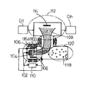
- the plasma generator 2 includes a cathode (cathode) 10, a trigger electrode 11, an anode (anode) 12, an arc power source 13, a cathode protector 14, and a plasma stabilizing magnetic field generator (electromagnetic coil or magnet) 15.
- the cathode 10 is a supply source of a plasma constituent material, and the forming material is not particularly limited as long as it is a conductive solid, and a single metal, an alloy, an inorganic simple substance, an inorganic compound (metal oxide / nitride) or the like is used alone. Or 2 or more types can be mixed and used.
- the cathode protector 14 electrically insulates other than the evaporating cathode surface and prevents the plasma generated between the cathode 10 and the anode 12 from diffusing backward.
- the material for forming the anode 12 is not particularly limited as long as it does not evaporate even at the plasma temperature and is a non-magnetic material having conductivity.
- the shape of the anode 12 is not particularly limited as long as it does not block the entire progress of the arc plasma.
- the plasma stabilizing magnetic field generator 15 is disposed on the outer periphery of the plasma generating unit 2 and stabilizes the plasma. When the arc stabilizing magnetic field generator 15 is arranged so that the magnetic fields applied to the plasma are in opposite directions (cusp shape), the plasma is further stabilized.
- the film forming rate by the plasma can be further improved.
- the plasma generating unit 2 and each plasma pipe are electrically insulated by the plasma generating unit side insulating plate 16, and even when a high voltage is applied to the plasma generating unit 2, the front part from the plasma straight tube 3 is electrically connected. In the floating state, the plasma is not electrically influenced in the plasma traveling path.
- a processing unit side insulating plate (not shown) is also interposed between the third plasma advancing tube 6 and the plasma processing unit 1, and is for plasma transfer from the plasma straight advancing tube 3 to the third plasma advancing tube 6. The entire duct section is set in an electrically floating state so that the plasma being transferred is not affected by an external power source (high voltage or GND).
- an electric spark is generated between the cathode 10 and the trigger electrode 11, and a vacuum arc is generated between the cathode 10 and the anode 12 to generate plasma.
- the constituent particles of the plasma include evaporating substances from the cathode 10 and charged particles (ions, electrons) originating from the evaporating substances and the reaction gas, as well as molecules in the pre-plasma state and neutral particles of atoms.
- droplets of sub-micron to several hundred microns (0.01-1000 ⁇ m) size are emitted.
- the droplet forms a mixed state with the plasma flow 26 and moves in the plasma traveling path as a droplet mixed plasma.
- a plasma transfer magnetic field generating means is provided. Plasma transport efficiency can be improved by generating a plasma transfer magnetic field in the entire three-stage bending path.
- the plasma advancing path is bent in three stages, magnetic field coils 21 and 23 for generating a bending magnetic field are attached to the tube connecting portions of the first plasma advancing tube 4 and the second plasma advancing tube 5, and the bending is performed.
- the plasma flow is bent and induced by a magnetic field. Since the bending magnetic field coil cannot be evenly wound at the connecting portion of the first plasma traveling tube 4 and the second plasma traveling tube 5, a magnetic field non-uniformity in which the bending magnetic field becomes strong is generated inside the bending portion.
- the first plasma traveling tube 4 and the second plasma traveling tube 5 are provided with deflection magnetic field generating means 22 and 24, respectively.
- the deflection magnetic field generation means 22 and 24 are composed of a deflection magnetic field generation coil 30 and a movable yoke 29.
- FIG. 3 shows a state in which the movable yoke 29 is disposed on the outer periphery of the second plasma advancing tube 5.
- the movable yoke 29 is wound with a deflection magnetic field generating coil 30 and has a pair of magnetic poles 27 and 28.
- a deflection magnetic field is generated between the magnetic poles 27 and 28 and applied to the plasma in the second plasma advancing tube 5.
- the deflection magnetic field generation means 22 and 24 include an adjustment mechanism that adjusts the movable yoke 29 by slide adjustment in the tube axis direction, rotation adjustment in the circumferential direction, and swing adjustment in the tube axis direction.
- FIG. 4 shows a rotation adjusting mechanism for the movable yoke 29 arranged on the outer periphery of the first plasma advancing tube 4.
- the rotation adjusting mechanism includes a guide body 31 provided with four arcuate guide grooves 32 for rotating and adjusting the movable yoke 29 in the circumferential direction.
- a pin 33 provided on the movable yoke 29 is inserted into the guide groove 32, and the movable yoke 29 can be rotationally adjusted within an angle adjustment range ⁇ 1 of 90 degrees or less by sliding the pin 33 in the pipe circumferential direction. . After the adjustment, the adjustment angle can be maintained by fastening the pin 33 to the guide body 31 with the fastening nut 34.
- FIG. 5 shows an adjustment mechanism for adjusting the sliding movement of the movable yoke 29 arranged on the outer periphery of the second plasma traveling tube 5 in the tube axis direction and swinging in the tube axis direction.
- the guide body 31 is supported by the slide member 35 in a state where the movable yoke 29 is fixedly held via the spacer 36.
- the slide member 35 has a linear slide groove 38 along the tube axis direction of the second plasma advancing tube 5, and is fixed to the adjustment unit main body 37.
- the slide groove 38 is formed in parallel to the inclined center line of the second plasma advancing tube 5.
- the slide groove installed in the first plasma advancing tube 4 is formed horizontally along the center line of the first plasma advancing tube 4.
- a pin 39 provided on the guide body 31 is inserted into the guide groove 38.
- the movable yoke 29 of the guide body 31 is slid and adjusted substantially over the tube length of the second plasma advancing tube. Can do.
- the adjustment position can be maintained by fastening the pin 39 to the slide member 35 with the fastening nut 40.
- the guide body 31 is supported by the slide member 35 so as to be rotatable around the axis of the pin 39 in a state where the movable yoke 29 is fixedly held.
- the movable yoke 29 can be adjusted to swing (tilt angle adjustment) in the tube axis direction.
- the adjustment tilt angle can be maintained by fastening the pin 39 to the slide member 35 with the fastening nut 40.
- the adjustable tilt angle is 5 ° on the first plasma advancing tube 4 side and 30 ° on the opposite side.
- the deflection magnetic field generating means 22 and 24 enable the movable yoke 29 to be slide adjusted in the tube axis direction, rotated in the circumferential direction, and swing adjusted in the tube axis direction, so that the position or angle of the movable yoke 29 is adjusted. Makes it possible to make fine adjustment by the deflection magnetic field to eliminate the nonuniformity of the magnetic field for plasma transfer, and to realize an optimal plasma traveling path consisting of the geometrical arrangement of the three stages of bending paths. .
- FIG. 6 (6A) schematically shows a state 19A in which the magnetic field coil for generating a magnetic field for plasma transfer is wound around the second plasma advancing tube 5 arranged in an inclined manner in a circular shape M1 along the inclination axis.
- a gap where the coil is not wound is formed in the vicinity of the connecting portion with another tube (4 or 6), and a non-uniform magnetic field is generated, resulting in a decrease in plasma transport efficiency.
- the magnetic field coil 19 wound around the outer periphery of the second plasma advancing tube 5 is composed of a magnetic field coil wound elliptically along the tilt axis with respect to the outer periphery of the tube.
- (6B) of FIG. 6 schematically shows a state 19B in which the magnetic field coil 19 for generating a magnetic field for carrying a plasma is wound around the second plasma advancing tube 5 arranged in an inclination in an elliptical shape M2 along the inclination axis. Since the magnetic field coil 19 wound in the elliptical shape M2 is installed in the second plasma advancing tube 5, a gap like the hatched area in (6A) does not occur. By winding a magnetic field coil, plasma transport efficiency can be improved without generating a non-uniform magnetic field, and plasma processing using high-density and high-purity plasma can be made possible.
- droplet collecting plates (baffles) 41, 42, 43 and 44 are planted. The structure of each collecting plate will be described in detail below.
- FIG. 7 is a partially enlarged cross-sectional view of the inner peripheral pipe 61 having the droplet collecting plate 60.
- the inner peripheral pipe 61 is accommodated in each plasma pipe (3 to 6), and a plurality of droplet collecting plates 60 are planted on the inner wall thereof.
- an opening 62 for plasma circulation is formed at the center of the droplet collecting plate 60.
- the plasma flows in from the upper side of the figure and passes through the opening 62.
- the inclination angle ⁇ of the droplet collecting plate 60 is set in the range of 15 to 90 °, it is experientially 30 to 60 °, and in this embodiment ⁇ is set to 60 °. At this inclination angle, the droplets separated from the plasma flow can be reliably attached and recovered while being subjected to multiple reflection on the droplet collecting plate 60.
- the droplet collection surface area in the inner peripheral pipe 61 is increased by the plurality of droplet collecting plates 60, and the scattered droplets can be adhered and collected in a large amount with certainty.
- the number of droplet collecting plates 60 is limited by the restriction of the tube length of the inner peripheral tube 61. Therefore, in order to increase the droplet removal area, the surface of the droplet collecting plate 60 is increased. It is preferable to perform roughening to form a rough surface having innumerable irregularities. That is, by roughening the surface of the droplet collection plate 60, the collection area of the droplet collection plate 60 is increased, and the collection efficiency can be improved.
- the droplet which collided with the recessed part is firmly fixed by the recessed part, and the droplet collecting efficiency is remarkably increased.
- line processing or satin processing can be used.
- line processing method for example, a polishing process using polishing paper is used.
- satin processing method for example, blasting using alumina, shots, grids, glass beads, or the like is used, and in particular, microblast processing in which several micron particles are accelerated by compressed air or the like and nozzle sprayed is used. Fine irregularities can be applied to the narrow surface.
- the planting area of the droplet collecting plate 60 is preferably 70% or more of the pipe inner wall area. In the case of FIG. 2, the planting area is about 90% of the inner wall area of the tube, and the droplet adhesion surface area in the tube for the plasma advancing path is increased so that a large amount of scattered droplets can be adhered and recovered reliably. Therefore, it is possible to achieve high purity of the plasma flow.
- the droplet collecting plate 60 is electrically cut off from the wall of each plasma traveling tube.
- a bias power source 63 as a bias voltage applying unit is connected to the inner peripheral tube 61, and the inner peripheral tube 61 can be set to a positive potential or a negative potential.
- the bias potential of the inner peripheral tube 61 is a positive potential, there is an effect of pushing out positive ions in the plasma in the transport direction, and in the case of a negative potential, there is an effect of pushing out electrons in the plasma in the transport direction.
- which of + and-is selected is selected in a direction that does not decrease the plasma transfer efficiency, and is determined by the state of the plasma.
- the potential intensity is also variable, and it is usually selected from the viewpoint of conveyance efficiency to set the inner peripheral tube 61 to + 15V.
- One or more apertures 70 that are movable along the tube axis direction may be disposed in the second plasma advancing tube 5.
- the aperture 70 has a structure in which the installation position can be changed along the tube axis direction in the second plasma advancing tube 5, and may have a structure that can move back and forth or a structure that can move only in one direction. . Since it is movable, the installation position of the aperture can be adjusted, and it can be taken out and washed.
- the aperture 70 has an opening of a predetermined area in the center, and the droplet is collided and captured by the wall surface around the opening, and the plasma passing through the opening advances.
- the opening may be provided in the center or may be designed in various ways, such as being provided at an eccentric position. Therefore, if a plurality of apertures 70 are movably installed in the second plasma advancing tube 5, the droplet removal efficiency increases and the plasma purity can be improved. In the following, a one-way moving aperture using a leaf spring is shown.
- FIG. 8 (8A) is a plan view of the movable aperture 70
- FIG. 8 (8B) shows a state in which the aperture 70 is attached.
- the aperture 70 has a ring shape having an opening 71 having a predetermined area in the center.
- the shape of the opening can be variously designed such as a circle or an ellipse according to the arrangement form.
- Stoppers 72 made of elastic pieces (for example, leaf springs) projecting outward are fixed to the three positions of the aperture 70 surface by screws 73, but a fixing method such as welding can be arbitrarily adopted.
- the protruding portion 74 of the elastic piece is bent downward. As shown in (8B) of FIG.
- a locking recess 76 for holding the aperture 70 is previously formed in a circular shape on the inner wall of the tube 75 of the second plasma advancing tube 5.
- a plurality of locking recesses 76 are provided along the longitudinal direction of the tube 75.
- the stopper 72 cannot be reversed and the aperture 70 can be set at the locked position.
- the stopper 72 is unlocked, and the protruding portion 74 can be reinserted and locked in the next locking recess 76.
- the aperture 70 has a structure that can move to an arbitrary set position in the second plasma advancing tube 5, the aperture 70 reduces the diameter of the second plasma advancing tube 5 to collect droplets, and further sets the set position. The amount of collection can be adjusted optimally by changing as appropriate, which contributes to improved droplet removal efficiency.
- the number of sets of apertures 70 is 1 or 2 or more.
- the opening 71 is not only provided at the center of the aperture 70, but can also be provided with a function of causing the plasma flow in the tube to meander by being eccentric.
- a ring-shaped aperture may be provided at a connecting portion in the plasma traveling path including the plasma straight traveling tube 3, the first plasma traveling tube 4, the second plasma traveling tube 5, and the third plasma traveling tube 6. Similar to the aperture 70, the arrangement of the apertures for the connecting portion reduces the diameter of the plasma traveling path or decenters it, or reduces or decenters it to collect more droplets contained in the plasma flow. Removal efficiency can be improved.
- the final stage third plasma advancing tube 6 has a uniform tube diameter, but the plasma flow discharged from the second plasma advancing tube 5 through a bent path. Is preferably further densified in the third plasma advancing tube 6.
- An embodiment in which the third plasma advancing tube 6 is further provided with a higher density function will be described below.
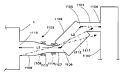
- FIG. 9 shows a schematic configuration of a plasma processing apparatus according to the third embodiment.
- the plasma processing apparatus of FIG. 9 includes a plasma generation unit (not shown) that generates plasma to be supplied to the plasma processing unit 1 and a plasma generation apparatus that includes a plasma traveling path, as in FIG.
- the droplet removing portion provided in the plasma traveling path includes a plasma straight tube 1100 connected to the plasma generating portion and a first plasma connected to the plasma straight tube 1100 in a bent shape through a connection port 1104.
- Advancing tube 1101 a second plasma advancing tube 1102 connected to the end of first plasma advancing tube 1101 at a predetermined bending angle with respect to the tube axis, and a bent to the end of second plasma advancing tube 1102 And a third plasma advancing tube 1103 that discharges plasma from the plasma outlet 1106.
- a droplet collecting plate and a plasma transfer magnetic field forming magnetic field coil are disposed in the plasma traveling path.
- the plasma advancing path composed of the straight plasma traveling tube 1100, the first plasma advancing tube 1101, the second plasma advancing tube 1102 and the third plasma advancing tube 1103 is bent and formed in three stages, similar to the plasma advancing path of FIGS. Has been.
- the third plasma advancing tube 1103 includes a rectifying tube 1107 connected to the end of the second plasma advancing tube 1102, a frustoconical tube 1108 serving as a deflection vibration tube connected to the rectifying tube 1107, and an outlet tube 1109.
- the frustoconical tube (deflection vibration tube) 1108 is expanded in diameter toward the outlet tube 1109 side.
- a plasma outlet 1110 of the outlet pipe 1109 is connected to a plasma inlet of the plasma processing unit 1.
- the outlet pipe 1109 has a uniform pipe diameter.
- the plasma advancing lengths L1 to L3 of the first plasma advancing tube 1101, the second plasma advancing tube 1102, and the third plasma advancing tube 1103 are the same as the respective plasma advancing tubes in FIG. It is set similarly.
- the second plasma advancing tube 1102 is geometrically arranged in the same manner as in FIGS. 1 and 2 at a position where the plasma outlet 1110 of the outlet tube 1109 does not see through the plasma outlet 1105 side of the first plasma advancing tube 1101 linearly. Has been.
- the elevation angle ( ⁇ ) from the upper end of the cross section on the plasma inlet side of the rectifying tube 1107 to the lower end of the cross section on the plasma outlet 1105 side of the first plasma advancing tube 1101 is
- ⁇ ⁇ ⁇ 0 is satisfied as in FIG. Has been. 1 and 2 avoids the straight droplets derived from the first plasma advancing tube 1101 from directly entering the third plasma advancing tube 1103, so that the third It is possible to prevent discharge from the plasma outlet 1110 of the plasma advancing tube 1103.
- the plasma flow meanders and diffuses at the end of the inclined second plasma traveling tube 1102 connected to the third plasma traveling tube 1103, and the plasma traveling efficiency toward the third plasma traveling tube 1103 decreases.
- a rectifying magnetic field coil 1114 is provided in the rectifying tube 1107 connected to the second plasma advancing tube, and the flow of plasma supplied from the second plasma advancing tube 1102 to the rectifying tube 1107 is forcibly focused.
- a rectifying magnetic field to be rectified is generated in the tube. With this rectifying magnetic field, the plasma flowing in the second plasma advancing tube 1102 can be drawn out in a focused manner toward the third plasma advancing tube 1103, and high-density and high-purity plasma can be generated.
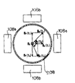
- FIG. 10 is an explanatory diagram of the magnetic field for scanning formed in the truncated cone tube (deflection vibration tube) 1108 (shown in FIG. 9) according to the third embodiment.
- a cone connected to a rectifying tube 1107 is used to oscillate a plasma flow focused and rectified by a rectifying magnetic field action left and right and up and down to scan the plasma flow like a CRT display.
- a trapezoidal tube (deflection vibration tube) 1108 is provided with a scanning magnetic field coil 1113.
- the scanning magnetic field coil 1113 includes a set of X-direction oscillating magnetic field generators 108a and 108a and a set of Y-directional oscillating magnetic field generators 108b and 108b.
- the scanning magnetic field B R (t) is a combined magnetic field of the X-direction oscillating magnetic field B X (t) and the Y-direction oscillating magnetic field B Y (t).
- the plasma flow is scanned up and down by the Y-direction oscillating magnetic field while the plasma flow is swung left and right by the X-direction oscillating magnetic field, and this is repeated to enable the plasma processing unit 1 to irradiate a large area plasma.
- the cross-sectional area of the plasma flow is smaller than the cross-sectional area of the workpiece disposed in the plasma processing chamber 1, the plasma flow is scanned up, down, left, and right to enable plasma irradiation on the entire surface of the workpiece.
- the same principle is used as when an electron beam of a CRT display moves up and down while vibrating left and right, and this operation is repeated to emit light on the entire display screen.
- the plasma generating apparatus can be provided with a droplet removing unit in the plasma traveling path, and a high-purity and uniform plasma flow can be introduced into the plasma processing unit.
- a high-purity plasma generated by the plasma generation apparatus according to the present invention is used, a high-purity thin film with significantly fewer defects and impurities is formed on the surface of the solid material in the plasma, or plasma is irradiated.
- the surface properties of solids can be uniformly modified without imparting defects or impurities.For example, high-strength / corrosion-resistant films on solid surfaces, protective films, optical thin films, transparent conductive films, etc.
- a plasma processing apparatus which can be formed with high quality and high accuracy can be provided.
Abstract
L'invention porte sur un appareil de génération de plasma. Selon l’invention, une gouttelette mélangée dans du plasma peut être efficacement retirée et une précision de traitement de surface peut être améliorée dans une formation de film dans laquelle un plasma de haute pureté est utilisé. L'invention porte également sur un appareil de traitement au plasma utilisant cet appareil de génération de plasma. Une section de retrait de gouttelette disposée dans un trajet de circulation de plasma est constituée par un tuyau de circulation de plasma droit (P0) relié à une section de génération de plasma (A) ; un premier tuyau de circulation de plasma (P1) relié au tuyau de circulation de plasma droit (P0) en étant courbé ; un deuxième tuyau de circulation de plasma (P2) relié à une extrémité du premier tuyau de circulation de plasma (P1) en étant disposé en diagonale selon un angle de flexion prescrit par rapport à l'axe de tuyau du premier tuyau de circulation de plasma ; et un troisième tuyau de circulation de plasma (P3), qui est relié à une extrémité du deuxième tuyau de circulation de plasma (P2) en étant courbé et qui décharge du plasma à partir d'un orifice de décharge de plasma.
Priority Applications (3)
| Application Number | Priority Date | Filing Date | Title |
|---|---|---|---|
| EP09724376.0A EP2267180A4 (fr) | 2008-03-27 | 2009-03-25 | Appareil de génération de plasma et appareil de traitement au plasma |
| US12/736,234 US8562800B2 (en) | 2008-03-27 | 2009-03-25 | Plasma generating apparatus and plasma processing apparatus |
| CN200980109110.9A CN101970710B (zh) | 2008-03-27 | 2009-03-25 | 等离子生成装置及等离子处理装置 |
Applications Claiming Priority (2)
| Application Number | Priority Date | Filing Date | Title |
|---|---|---|---|
| JP2008083750A JP4568768B2 (ja) | 2008-03-27 | 2008-03-27 | プラズマ生成装置及びプラズマ処理装置 |
| JP2008-083750 | 2008-03-27 |
Publications (1)
| Publication Number | Publication Date |
|---|---|
| WO2009119655A1 true WO2009119655A1 (fr) | 2009-10-01 |
Family
ID=41113847
Family Applications (1)
| Application Number | Title | Priority Date | Filing Date |
|---|---|---|---|
| PCT/JP2009/055935 WO2009119655A1 (fr) | 2008-03-27 | 2009-03-25 | Appareil de génération de plasma et appareil de traitement au plasma |
Country Status (5)
| Country | Link |
|---|---|
| US (1) | US8562800B2 (fr) |
| EP (1) | EP2267180A4 (fr) |
| JP (1) | JP4568768B2 (fr) |
| CN (1) | CN101970710B (fr) |
| WO (1) | WO2009119655A1 (fr) |
Cited By (2)
| Publication number | Priority date | Publication date | Assignee | Title |
|---|---|---|---|---|
| WO2010113544A1 (fr) * | 2009-03-31 | 2010-10-07 | 株式会社フェローテック | Dispositif de traitement par plasma avec des isolants interposés |
| DE102010024244A1 (de) * | 2010-06-18 | 2011-12-22 | Werner Grimm | Anordnung und Verfahren für die dropletarme Beschichtung |
Families Citing this family (3)
| Publication number | Priority date | Publication date | Assignee | Title |
|---|---|---|---|---|
| UA97584C2 (ru) * | 2010-11-08 | 2012-02-27 | Национальный Научный Центр "Харьковский Физико-Технический Институт" | СПОСОБ ТРАНСПОРТИРОВКИ Вакуумно-дуговой Катодной ПЛАЗМЫ С фильтрованием От макрочастиц И УСТРОЙСТВО ДЛЯ ЕГО ОСУЩЕСТВЛЕНИЯ |
| JP6042279B2 (ja) * | 2013-07-16 | 2016-12-14 | 株式会社システム技研 | 基板成膜処理用マスクホルダに使用される係止部材、及び基板成膜処理用マスクホルダ |
| CN111841493A (zh) * | 2020-06-24 | 2020-10-30 | 东南大学 | 一种增加活性炭含氧官能团的提质装置 |
Citations (8)
| Publication number | Priority date | Publication date | Assignee | Title |
|---|---|---|---|---|
| JPH0513036A (ja) * | 1991-07-03 | 1993-01-22 | Origin Electric Co Ltd | イオンビーム照射方法およびその装置 |
| JP2002008893A (ja) | 2000-06-16 | 2002-01-11 | Ito Kogaku Kogyo Kk | プラズマ加工法 |
| JP2002069621A (ja) * | 2000-08-25 | 2002-03-08 | Ulvac Japan Ltd | 炭化ケイ素膜の形成方法 |
| JP2002105628A (ja) | 2000-10-03 | 2002-04-10 | Nissin Electric Co Ltd | 真空アーク蒸着装置 |
| JP2003178708A (ja) * | 2001-12-10 | 2003-06-27 | Nissin Electric Co Ltd | イオン注入装置 |
| JP2005216575A (ja) * | 2004-01-28 | 2005-08-11 | Hiroshi Takigawa | プラズマ生成装置 |
| JP2005264255A (ja) * | 2004-03-19 | 2005-09-29 | Shimadzu Corp | カソーディックアーク成膜方法および成膜装置 |
| JP2006274294A (ja) * | 2005-03-28 | 2006-10-12 | Toyohashi Univ Of Technology | プラズマ生成装置におけるドロップレット除去装置及びドロップレット除去方法 |
Family Cites Families (7)
| Publication number | Priority date | Publication date | Assignee | Title |
|---|---|---|---|---|
| JPH05130036A (ja) | 1991-10-31 | 1993-05-25 | Sony Corp | 遠隔操作装置 |
| US5476691A (en) * | 1994-01-21 | 1995-12-19 | International Business Machines, Inc. | Surface treatment of magnetic recording heads |
| CA2305938C (fr) * | 2000-04-10 | 2007-07-03 | Vladimir I. Gorokhovsky | Methode et appareillage de depot d'arc cathodique filtre |
| US7033462B2 (en) * | 2001-11-30 | 2006-04-25 | Nissin Electric Co., Ltd. | Vacuum arc vapor deposition process and apparatus |
| US7381311B2 (en) * | 2003-10-21 | 2008-06-03 | The United States Of America As Represented By The Secretary Of The Air Force | Filtered cathodic-arc plasma source |
| JP4889957B2 (ja) * | 2005-03-25 | 2012-03-07 | 株式会社フェローテック | プラズマ生成装置におけるドロップレット除去装置及びドロップレット除去方法 |
| JP4660452B2 (ja) * | 2006-09-30 | 2011-03-30 | 株式会社フェローテック | 拡径管型プラズマ生成装置 |
-
2008
- 2008-03-27 JP JP2008083750A patent/JP4568768B2/ja active Active
-
2009
- 2009-03-25 WO PCT/JP2009/055935 patent/WO2009119655A1/fr active Application Filing
- 2009-03-25 EP EP09724376.0A patent/EP2267180A4/fr not_active Withdrawn
- 2009-03-25 US US12/736,234 patent/US8562800B2/en active Active
- 2009-03-25 CN CN200980109110.9A patent/CN101970710B/zh active Active
Patent Citations (8)
| Publication number | Priority date | Publication date | Assignee | Title |
|---|---|---|---|---|
| JPH0513036A (ja) * | 1991-07-03 | 1993-01-22 | Origin Electric Co Ltd | イオンビーム照射方法およびその装置 |
| JP2002008893A (ja) | 2000-06-16 | 2002-01-11 | Ito Kogaku Kogyo Kk | プラズマ加工法 |
| JP2002069621A (ja) * | 2000-08-25 | 2002-03-08 | Ulvac Japan Ltd | 炭化ケイ素膜の形成方法 |
| JP2002105628A (ja) | 2000-10-03 | 2002-04-10 | Nissin Electric Co Ltd | 真空アーク蒸着装置 |
| JP2003178708A (ja) * | 2001-12-10 | 2003-06-27 | Nissin Electric Co Ltd | イオン注入装置 |
| JP2005216575A (ja) * | 2004-01-28 | 2005-08-11 | Hiroshi Takigawa | プラズマ生成装置 |
| JP2005264255A (ja) * | 2004-03-19 | 2005-09-29 | Shimadzu Corp | カソーディックアーク成膜方法および成膜装置 |
| JP2006274294A (ja) * | 2005-03-28 | 2006-10-12 | Toyohashi Univ Of Technology | プラズマ生成装置におけるドロップレット除去装置及びドロップレット除去方法 |
Non-Patent Citations (2)
| Title |
|---|
| P.J. MARTIN; R.P. NETTERFIELD; T.J. KINDER, THIN SOLID FILMS, vol. 193, 194, 1990, pages 77 |
| See also references of EP2267180A4 |
Cited By (3)
| Publication number | Priority date | Publication date | Assignee | Title |
|---|---|---|---|---|
| WO2010113544A1 (fr) * | 2009-03-31 | 2010-10-07 | 株式会社フェローテック | Dispositif de traitement par plasma avec des isolants interposés |
| US8999122B2 (en) | 2009-03-31 | 2015-04-07 | Ferrotec Corporation | Insulator interposed type plasma processing apparatus |
| DE102010024244A1 (de) * | 2010-06-18 | 2011-12-22 | Werner Grimm | Anordnung und Verfahren für die dropletarme Beschichtung |
Also Published As
| Publication number | Publication date |
|---|---|
| JP4568768B2 (ja) | 2010-10-27 |
| CN101970710B (zh) | 2013-06-05 |
| CN101970710A (zh) | 2011-02-09 |
| US20110068004A1 (en) | 2011-03-24 |
| EP2267180A1 (fr) | 2010-12-29 |
| US8562800B2 (en) | 2013-10-22 |
| EP2267180A4 (fr) | 2014-11-05 |
| JP2009235500A (ja) | 2009-10-15 |
Similar Documents
| Publication | Publication Date | Title |
|---|---|---|
| JP4576467B2 (ja) | 絶縁体介装型プラズマ処理装置 | |
| US7381311B2 (en) | Filtered cathodic-arc plasma source | |
| JP4660452B2 (ja) | 拡径管型プラズマ生成装置 | |
| JP4568768B2 (ja) | プラズマ生成装置及びプラズマ処理装置 | |
| JP2008248347A (ja) | プラズマガン周辺を電気的中性にしたプラズマ生成装置 | |
| US10840054B2 (en) | Charged-particle source and method for cleaning a charged-particle source using back-sputtering | |
| CZ293994B6 (cs) | Holicí břit, způsob jeho výroby, a holicí jednotka | |
| JP4690477B2 (ja) | 陽極壁多分割型プラズマ発生装置及びプラズマ処理装置 | |
| TWI732817B (zh) | 離子束裝置中汙染控制的裝置和方法 | |
| JP2003520393A (ja) | ガスクラスターイオンビーム形成用イオン化装置 | |
| KR20220130705A (ko) | 미립자 파편의 궤적을 변경하기 위한 편향 장치를 구비한 리소그래피 시스템 | |
| US9426875B2 (en) | Method for producing plasma flow, method for plasma processing, apparatus for producing plasma, and apparatus for plasma processing | |
| EP3518268A1 (fr) | Source de particules chargées et procédé de nettoyage d'une source de particules chargées à l'aide de rétropulvérisation | |
| JP3079802B2 (ja) | プラズマ銃 | |
| EP1255277B1 (fr) | Ionisateur pour formation d'un faisceu d'agglomerats ionisés | |
| KR101716848B1 (ko) | 공간형 이온 빔 발생 장치 | |
| JP2001011608A (ja) | 膜形成装置 | |
| JP3057039U (ja) | アークイオンメッキユニットの磁場発生装置 | |
| JP2001234333A (ja) | 金属プラズマを用いた成膜装置及び方法 | |
| JP2012067352A (ja) | 終端反射壁フィルタを有するプラズマ生成装置及びプラズマ加工装置 | |
| JPH0445262A (ja) | 真空アーク蒸着装置 | |
| JP2006161122A (ja) | 成膜装置 | |
| JP2000067792A (ja) | 荷電粒子線露光装置 |
Legal Events
| Date | Code | Title | Description |
|---|---|---|---|
| WWE | Wipo information: entry into national phase |
Ref document number: 200980109110.9 Country of ref document: CN |
|
| 121 | Ep: the epo has been informed by wipo that ep was designated in this application |
Ref document number: 09724376 Country of ref document: EP Kind code of ref document: A1 |
|
| NENP | Non-entry into the national phase |
Ref country code: DE |
|
| WWE | Wipo information: entry into national phase |
Ref document number: 2009724376 Country of ref document: EP |
|
| WWE | Wipo information: entry into national phase |
Ref document number: 12736234 Country of ref document: US |