WO2009118961A1 - Structure de raccordement de bride - Google Patents
Structure de raccordement de bride Download PDFInfo
- Publication number
- WO2009118961A1 WO2009118961A1 PCT/JP2008/072570 JP2008072570W WO2009118961A1 WO 2009118961 A1 WO2009118961 A1 WO 2009118961A1 JP 2008072570 W JP2008072570 W JP 2008072570W WO 2009118961 A1 WO2009118961 A1 WO 2009118961A1
- Authority
- WO
- WIPO (PCT)
- Prior art keywords
- flange
- sealing liquid
- seal groove
- flanges
- joint structure
- Prior art date
Links
- 238000007789 sealing Methods 0.000 claims abstract description 193
- 239000007788 liquid Substances 0.000 claims abstract description 186
- 238000002347 injection Methods 0.000 claims description 104
- 239000007924 injection Substances 0.000 claims description 104
- 230000002093 peripheral effect Effects 0.000 claims description 47
- 239000012530 fluid Substances 0.000 claims description 34
- 230000005856 abnormality Effects 0.000 claims description 28
- 238000001514 detection method Methods 0.000 claims description 13
- 230000007423 decrease Effects 0.000 claims description 8
- 239000007789 gas Substances 0.000 description 99
- 238000010586 diagram Methods 0.000 description 6
- UFHFLCQGNIYNRP-UHFFFAOYSA-N Hydrogen Chemical compound [H][H] UFHFLCQGNIYNRP-UHFFFAOYSA-N 0.000 description 4
- 238000004140 cleaning Methods 0.000 description 4
- 238000007689 inspection Methods 0.000 description 4
- XLYOFNOQVPJJNP-UHFFFAOYSA-N water Substances O XLYOFNOQVPJJNP-UHFFFAOYSA-N 0.000 description 4
- 230000002159 abnormal effect Effects 0.000 description 2
- 230000000903 blocking effect Effects 0.000 description 2
- 230000005484 gravity Effects 0.000 description 2
- 238000012423 maintenance Methods 0.000 description 2
- 238000000926 separation method Methods 0.000 description 2
- 230000005514 two-phase flow Effects 0.000 description 2
- 239000000126 substance Substances 0.000 description 1
- 238000003466 welding Methods 0.000 description 1
Images


Classifications
-
- F—MECHANICAL ENGINEERING; LIGHTING; HEATING; WEAPONS; BLASTING
- F16—ENGINEERING ELEMENTS AND UNITS; GENERAL MEASURES FOR PRODUCING AND MAINTAINING EFFECTIVE FUNCTIONING OF MACHINES OR INSTALLATIONS; THERMAL INSULATION IN GENERAL
- F16L—PIPES; JOINTS OR FITTINGS FOR PIPES; SUPPORTS FOR PIPES, CABLES OR PROTECTIVE TUBING; MEANS FOR THERMAL INSULATION IN GENERAL
- F16L23/00—Flanged joints
- F16L23/16—Flanged joints characterised by the sealing means
- F16L23/167—Flanged joints characterised by the sealing means in connection with the appearance or detection of leaks
-
- F—MECHANICAL ENGINEERING; LIGHTING; HEATING; WEAPONS; BLASTING
- F16—ENGINEERING ELEMENTS AND UNITS; GENERAL MEASURES FOR PRODUCING AND MAINTAINING EFFECTIVE FUNCTIONING OF MACHINES OR INSTALLATIONS; THERMAL INSULATION IN GENERAL
- F16L—PIPES; JOINTS OR FITTINGS FOR PIPES; SUPPORTS FOR PIPES, CABLES OR PROTECTIVE TUBING; MEANS FOR THERMAL INSULATION IN GENERAL
- F16L2201/00—Special arrangements for pipe couplings
- F16L2201/30—Detecting leaks
Definitions
- the present invention relates to a flange joint structure, and has been devised to improve sealing performance by using a sealing liquid when joining pipes or the like with a flange, or when joining a manhole and a lid of a tank with a flange. Is.
- this invention it devised so that the sealing performance with respect to the fluid, especially the fluid containing gas (gas) may be improved.
- one pipe and the other pipe may be flange-bonded for convenience of pipe connection, and a tank manhole and a lid that closes the tank may be flange-bonded.
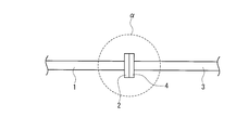
- FIG. 9 shows a conventional flange joint structure applied to piping.
- a flange 2 is formed on one pipe 1
- a flange 4 is formed on the other pipe 3.
- the flange surfaces of the flange 2 and the flange surfaces of the flange 4 are connected to each other. It is made to join.
- the piping 1 and the piping 4 are connected.
- the pipes 1 and 3 are connected to each other by such a flange joint structure, when the pipes 1 and 3 are opened for maintenance, inspection or cleaning, the bolts that fasten the flanges 2 and 4 are fastened.
- the pipes 1 and 3 can be opened simply by loosening and removing. Further, at the time of restoration, it is only necessary to perform a simple operation of fastening the flanges 2 and 4 with bolts.
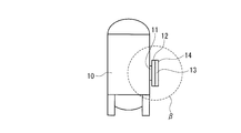
- FIG. 10 shows a conventional flange connection structure applied to a tank.
- a flange 12 is formed on the manhole 11 of the tank 10
- a flange 14 is formed on the lid 13.
- a gasket is interposed between the flange surface of the flange 12 and the flange surface of the flange 14, and the flanges 12 and 14 are fastened with bolts (not shown), so that the flange surface of the flange 12 and the flange surface of the flange 14 are connected to each other. It is made to join. As a result, the manhole 11 is closed by the lid 13.
- the manhole 11 is closed with the lid 13 by such a flange joint structure, when opening the tank 10 for maintenance, inspection or cleaning, the bolts fastening the flanges 12 and 14 are loosened.
- the tank 10 can be opened simply by removing it. Further, at the time of restoration, it is only necessary to perform a simple operation of fastening the flanges 12 and 14 with bolts.
- the flange joint structure of the pipe and the flange joint structure of the tank manhole were considered to be a sealing structure capable of complete sealing.
- the peripheral region ⁇ of the flange joint structure shown in FIG. 9 is designated as the explosion-proof range, or the peripheral region ⁇ of the flange joint structure shown in FIG. 10 is designated as the explosion-proof range.
- the region ⁇ and region ⁇ designated as the explosion-proof range no device or instrument serving as an ignition source is installed, or a specially designed device or meter is used.
- the degree of freedom in designing the plant is limited and costs are increased.
- the present invention is a flange joint structure that enhances sealing performance in a flange joint structure that connects pipes, a connection structure between tanks and devices, a flange joint structure that closes a manhole of a tank with a lid, and the like.
- the purpose is to provide.
- the structure of the present invention that solves the above problem is a flange joint structure that joins and connects the flange surfaces of the flanges by bolting one flange and the other flange, An annular seal groove is formed on the flange surface of one of the flanges, and a sealing liquid is press-fitted and filled into the seal groove.
- the configuration of the present invention is a flange joint structure that joins and connects the flange surfaces of the flanges by bolting one flange and the other flange, or a flange and a lid formed in a manhole of a tank.
- An annular seal groove formed on the flange surface of one of the flanges An injection path formed on the one flange, communicating between the seal groove and the outer surface of the one flange, and injecting a sealing liquid from the outside; It has a discharge passage formed on the one flange and communicating with the seal groove, and is discharged through the injection passage and discharges the sealing liquid filling the seal groove to the outside.
- the configuration of the present invention is such that the flange surfaces of the flanges are joined to each other by bolting a flange formed on one pipe through which fluid flows and a flange formed on the other pipe through which fluid flows.
- a flange joint structure for connecting pipes or a flange formed on a manhole of a tank for storing fluid and a flange formed on a lid by bolting the flange surfaces of the flanges to join the manholes Flange joint structure in which the flange is closed by the lid, or a flange joint structure in which the flange surfaces of the flange are joined by bolting a flange formed in the pipe and a flange formed in the lid, and the pipe is closed by the lid.
- An annular seal groove formed on the flange surface of one of the flanges; An injection path formed on the one flange and communicating between the seal groove and an outer surface of the one flange; A discharge passage formed in the one flange and communicating between the seal groove and an outer surface of the one flange; A sealing liquid injection means connected to the injection path and injecting a sealing liquid into the seal groove; A discharge device that is connected to the discharge path and discharges the gas contained in the seal liquid to the outside while preventing the seal liquid from the discharge path from being discharged to the outside.
- the configuration of the present invention is characterized in that the injection pressure of the sealing liquid injected by the sealing liquid injection means is set lower than the fluid pressure of the fluid.
- the configuration of the present invention is such that the flange surfaces of the flanges are joined to each other by bolting a flange formed on one pipe through which fluid flows and a flange formed on the other pipe through which fluid flows.
- a flange joint structure for connecting pipes or a flange formed on a manhole of a tank for storing fluid and a flange formed on a lid by bolting the flange surfaces of the flanges to join the manholes Flange joint structure in which the flange is closed by the lid, or a flange joint structure in which the flange surfaces of the flange are joined by bolting a flange formed in the pipe and a flange formed in the lid, and the pipe is closed by the lid.
- An annular seal groove formed on the flange surface of one of the flanges; An injection path formed on the one flange and communicating between the seal groove and an outer surface of the one flange; A discharge path that is formed in the one flange and communicates between the seal groove and a space where the fluid exists on the inner peripheral side of the flange; And a sealing liquid injection means for injecting a sealing liquid into the sealing groove connected to the injection path.
- the configuration of the present invention is characterized in that the injection pressure of the sealing liquid injected by the sealing liquid injection means is set higher than the fluid pressure of the fluid.
- the sealing liquid injection means detects pressure of the sealing liquid injected into the injection path, or detects a flow rate of the sealing liquid injected into the injection path.
- a flow rate detection means is provided, When there is a sudden decrease in the pressure detected by the pressure detection means, or when the flow rate detected by the flow rate detection means has increased rapidly, there is provided an abnormality determination means for determining that an abnormality has occurred in the joining of the flanges. It is characterized by.
- the annular seal groove is formed on the flange surface of the flange, and the sealing liquid is press-fitted and filled in the seal groove.
- a liquid seal structure is constituted by the sealing liquid press-fitted and filled in the seal groove, and the sealing performance of the flange can be improved.
- the frequency of occurrence of leaks from the flange joint structure can be drastically reduced, and there is no need to make the surroundings of the flange joint structure an explosion-proof range, etc., and the degree of freedom in designing piping and the like can be improved.
- a flange joint structure can be adopted, open inspection and cleaning can be easily performed.
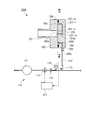
- FIG. 1 is a configuration diagram showing a flange joint structure for piping according to Embodiment 1 of the present invention.
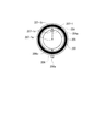
- FIG. 2 is a view taken along the line II-II in FIG.
- FIG. 3 is a configuration diagram showing a flange joint structure for piping according to Embodiment 2 of the present invention.
- 4 is a view taken in the direction of arrows IV-IV in FIG.
- FIG. 5 is a configuration diagram showing a flange joint structure for a tank or the like according to Embodiment 3 of the present invention.
- 6 is a view taken in the direction of arrows VI-VI in FIG.
- FIG. 7 is a configuration diagram showing a flange joint structure for a tank or the like according to Embodiment 4 of the present invention.
- FIG. 8 is a view taken along arrow VIII-VIII in FIG.
- FIG. 9 is a block diagram showing a conventional flange joint structure applied to piping.
- FIG. 10 is a configuration diagram
- FIG. 1 shows a flange joint structure 100 for piping according to Embodiment 1 of the present invention
- FIG. 2 shows a view taken along the arrow II-II in FIG.
- a flange 102 is formed on one pipe 101, and a flange 104 is formed on the other pipe 103.
- the flanges 102 and 104 are fastened with bolts (not shown) to join the flange surface 102a of the flange 102 and the flange surfaces 104a of the flange 104 together.
- the piping 101 and the piping 103 are connected.
- combustible gas for example, hydrogen gas
- gas pressure gas pressure
- An annular seal groove 105 is formed on the flange surface 104 a of the flange 104.
- the seal groove 105 is formed on the outer peripheral side of the inner peripheral edge of the flange 104 and in a state of surrounding the inner peripheral surface of the flange 104.
- the flange 104 is formed with an injection path 106 and a discharge path 107.
- the injection path 106 and the discharge path 107 are formed by being shifted by 180 °.
- the injection path 106 is disposed on the lower side and the discharge path 107 is disposed on the upper side.
- One end 106 a of the injection path 106 opens to the peripheral surface of the outer surface of the flange 104, and the other end 106 b opens to the seal groove 105 to communicate between the seal groove 105 and the flange peripheral surface.
- the injection path 106 extends substantially vertically upward from one end 106a and then bends in the horizontal direction to reach the other end 106b.
- the discharge passage 107 has one end 107 a that opens to the peripheral surface of the outer peripheral surface of the flange 104, and the other end 107 b that opens to the seal groove 105, thereby communicating between the seal groove 105 and the flange peripheral surface. .
- the discharge path 107 extends from the one end 107a substantially downward in the vertical direction and then bends in the horizontal direction to reach the other end 107b.
- annular gaskets 108 and 109 are interposed between the flange surface 102a of the flange 102 and the flange surface 104a of the flange 104.
- the gasket 108 is disposed on the inner peripheral side with respect to the seal groove 105
- the gasket 109 is disposed on the outer peripheral side with respect to the seal groove 105.
- An annular gasket 108, a seal groove 105, and a gasket 109 are arranged concentrically.
- the sealing liquid injection unit 110 includes a sealing liquid injection source 111 that discharges a sealing liquid (for example, water or oil).
- a sealing liquid for example, water or oil
- the discharge port of the sealing liquid injection source 111 and one end 106 a of the injection path 106 are connected by an injection pipe 112.
- the injection pipe 112 is provided with a control valve 113, an orifice 114 and a check valve 115, and a pressure gauge 116 is attached.
- the injection pressure of the sealing liquid injected from the sealing liquid injection unit 110 into the seal groove 105 via the injection pipe 112 and the injection path 106 is the gas pressure of the combustible gas flowing in the pipes 101 and 103. Set lower than.
- the pressure gauge 116 detects the pressure of the sealing liquid injected into the injection path 106 and sends the detected pressure value to the abnormality determination unit 117.
- the abnormality determination unit 117 determines that an abnormality has occurred when the detected pressure value suddenly decreases, and takes a safety measure such as shutting off the flow of fluid in the pipe 101 when the abnormality is determined so as to close the control valve 113. It has become.
- the sealing liquid is injected into one flange joint structure 100 from one sealing liquid injection source 111, but the sealing liquid can be injected into a plurality of flange joint structures arranged in the piping system.
- the injection tube 112 can be arranged.
- the discharge device 120 is connected to one end 107 a of the discharge path 107 via the discharge pipe 121.
- the discharge device 120 has a float mechanism and an exhaust valve.
- the gas discharged from the discharge device 120 is discharged to the atmosphere via the exhaust pipe 122.
- This discharge position is set at a safe place away from the plant where the pipes 101 and 103 are installed.
- a gas detection sensor 123 is disposed in the exhaust pipe 122.
- the gas detection sensor 123 detects the type of gas released through the exhaust pipe 122.
- the safety device 124 is connected to the discharge pipe 121, and when the pressure of the sealing liquid in the discharge pipe 121 rises abnormally, the sealing liquid is discharged to the outside.
- the sealing liquid when the sealing liquid is discharged / injected from the sealing liquid injection source 111 of the sealing liquid injection unit 110, the sealing liquid is injected into the injection pipe 112, the injection path 106, The seal groove 105, the discharge passage 107, the discharge pipe 121, and the discharge device 120 are press-fitted and filled. At this time, the air previously contained in each pipe is released into the atmosphere via the discharge device 120.
- the sealing liquid is press-fitted and filled into the annular sealing groove 105, whereby the liquid sealing structure is constituted by the sealing liquid in the sealing groove 105. Therefore, the positive pressure combustible gas flowing through the pipes 101 and 103 is double-sealed by the gasket 108 on the inner peripheral side and the liquid seal structure in which the sealing groove 105 is filled with the sealing liquid. It will be.
- the sealing is performed not only by the gasket 108 but also by the liquid sealing structure in which the sealing liquid 105 is filled with the sealing liquid, so that more reliable sealing can be performed. .
- the explosion-proof range around the flange joint structure 100 can be limited to a minimum.
- the gasket 109 on the outer peripheral side functions to prevent the sealing liquid from leaking outside.
- the pressure of the sealing liquid is lower than the gas pressure of the combustible gas flowing through the pipes 101 and 103, the sealing liquid does not enter the pipes 101 and 103. This prevents the sealing liquid from entering the combustible gas.
- the discharge device 120 releases only the combustible gas to the outside (in the atmosphere) through the exhaust pipe 122 without releasing the sealing liquid. Since the discharge position for releasing the combustible gas to the atmosphere via the exhaust pipe 122 is a safe place away from the plant where the pipes 101 and 103 are installed, there is no problem even if the combustible gas is released. .
- the gas detection sensor 123 can detect that the combustible gas has circulated.
- the gas detection sensor 123 detects the flow of the combustible gas, it is possible to take safety measures such as issuing an alarm or stopping the flow of the combustible gas flowing through the pipes 101 and 103.
- the sealing liquid expands due to the heat of the combustible gas flowing through the pipes 101 and 103 and the heat of the atmosphere around the flange, and the pressure becomes extremely high, the safety device 124 is activated, and the seal The working liquid is discharged to the outside. For this reason, even if the sealing liquid is thermally expanded, it is possible to prevent the flanges 102 and 104 from being damaged and the pipe and the like filled with the sealing liquid from being damaged.
- the abnormality determination unit 117 determines that an abnormality has occurred, takes safety measures such as blocking the flow of fluid in the pipe 101, and closes the control valve 113. Thereby, the further outside outflow of the sealing liquid can be prevented.
- a flow meter is installed instead of the pressure gauge 116, and when the detected flow rate value detected by the flow meter increases rapidly, the abnormality determination unit 117 determines that an abnormality has occurred and closes the control valve 113. May be.
- Example 1 it is assumed that a combustible gas (only gas) is circulated through the pipes 101 and 103. However, even when a two-phase fluid in which a gas and a liquid are mixed flows through the pipes 101 and 103, Example 1 can be applied as it is.
- FIG. 3 shows a flange connection structure 100A for piping according to Embodiment 2 of the present invention
- FIG. 4 shows a view taken along arrows IV-IV in FIG.
- the same parts as those in the first embodiment shown in FIGS. 1 and 2 are denoted by the same reference numerals, and the description of the overlapping parts is simplified.
- a combustible gas for example, hydrogen gas
- a positive gas pressure gas pressure
- An annular seal groove 105 is formed on the flange surface 104 a of the flange 104.
- the seal groove 105 is formed on the outer peripheral side of the inner peripheral edge of the flange 104 and in a state of surrounding the inner peripheral surface of the flange 104.
- the flange 104 is formed with an injection path 106 and a discharge path 107-1.
- One end 106 a of the injection path 106 opens to the peripheral surface of the outer surface of the flange 104, and the other end 106 b opens to the seal groove 105 to communicate between the seal groove 105 and the flange peripheral surface. .
- One end 107-1a of the discharge passage 107-1 opens into the space on the inner peripheral side of the flange 104, and the other end 107-1b opens into the seal groove 105. They communicate with each other.
- the second embodiment is different from the first embodiment in that the one end 107-1a of the discharge passage 107-1 is open to the space on the inner peripheral side of the flange 104.
- a leakage restricting device 107-1c for restricting leakage of the sealing liquid may be provided at one end 107-1a of the discharge passage 107-1.
- An annular gasket 109 is interposed between the flange surface 102 a of the flange 102 and the flange surface 104 a of the flange 104.
- the sealing liquid injection unit 110 includes a sealing liquid injection source 111 that discharges a sealing liquid (for example, water or oil), an injection pipe 112, a control valve 113, an orifice 114, a check valve 115, a pressure gauge 116, and an abnormality determination unit. 117.
- a sealing liquid injection source 111 that discharges a sealing liquid (for example, water or oil)
- an injection pipe 112 that discharges a sealing liquid (for example, water or oil)
- a control valve 113 for example, an orifice 114, a check valve 115, a pressure gauge 116, and an abnormality determination unit.
- the injection pressure of the sealing liquid injected from the sealing liquid injection unit 110 into the seal groove 105 via the injection pipe 112 and the injection path 106 is the gas pressure of the combustible gas flowing in the pipes 101 and 103.
- the injection pressure of the sealing liquid is assumed to be lower than the gas pressure of the combustible gas flowing in the pipes 101 and 103.
- the injection pressure of the sealing liquid is the pipe. The difference is that it is assumed to be higher than the gas pressure of the combustible gas flowing through the inside of 101,103.
- the sealing liquid when the sealing liquid is discharged / injected from the sealing liquid injection source 111 of the sealing liquid injection unit 110, the sealing liquid passes through the injection pipe 112 and the injection path 106.
- the seal groove 105 is press-fitted and filled. Further, the sealing liquid press-fitted and filled in the seal groove 105 is discharged into the pipe 103 through the discharge path 107-1 and flows through the pipe 103. That is, if the sealing groove 105 is filled with the sealing liquid and the pressure of the sealing liquid is made higher than that of the fluid flowing in the pipes 101 and 103, the sealing performance is improved.
- the liquid leaking into the pipe 103 can be adjusted by the leakage restricting device 107-1c.
- the leaked liquid is gas-liquid separated and recovered by an appropriate separation device (not shown). Therefore, it is very efficient to use a gas-liquid two-phase flow liquid as the sealing liquid.
- the sealing liquid is press-fitted and filled into the annular sealing groove 105, whereby the liquid sealing structure is constituted by the sealing liquid in the sealing groove 105. Therefore, the positive pressure combustible gas flowing through the pipes 101 and 103 is reliably sealed by the liquid seal structure in which the seal groove 105 is filled with the high pressure sealing liquid.
- the explosion-proof range around the flange joint structure 100A can be limited to a minimum.
- the outer peripheral gasket 109 functions to prevent the sealing liquid from leaking outside.
- the liquid seal structure in which the sealing groove 105 is filled with the sealing liquid provides a reliable seal because the sealing is performed.
- the sealing liquid may leak more into the pipes 101 and 103 than usual, but the combustible gas does not leak to the outside. That is, even if a gap or the like occurs on the flange joint surface, gas leak can be prevented.
- the abnormality determination unit 117 determines that an abnormality has occurred, takes safety measures such as blocking the flow of fluid in the pipe 101, and closes the control valve 113. Thereby, the further outside outflow of the sealing liquid can be prevented.
- a flow meter is installed instead of the pressure gauge 116, and when the detected flow rate value detected by the flow meter increases rapidly, the abnormality determination unit 117 determines that an abnormality has occurred and closes the control valve 113. May be.
- Example 2 it is assumed that a combustible gas (only gas) is circulated through the pipes 101 and 103. However, even when a two-phase fluid in which a gas and a liquid are mixed flows through the pipes 101 and 103, Example 2 can be applied as it is.
- FIG. 5 shows a pipe end sealing lid or tank flange joint structure 200 according to Embodiment 3 of the present invention
- FIG. 6 is a view taken along the line VI-VI in FIG.
- performs the same function as Example 1 attaches
- a flange 202 is formed in the manhole 201 formed in the tank (not shown), and a flange 204 is formed in the lid 203.
- the flanges 202 and 204 are fastened with bolts (not shown) to join the flange surface 202a of the flange 202 and the flange surfaces 204a of the flange 204 together.
- the manhole 201 is closed by the lid 203.
- the manhole 201 is closed with a lid 203 to seal the combustible gas (for example, hydrogen gas) stored in the tank and having a positive gas pressure (gas pressure).
- this (manhole 201) is made into piping instead of the manhole 201, the lid
- An annular seal groove 205 is formed on the flange surface 204 a of the flange 204.
- the seal groove 205 on the lid 203 side is formed on the outer peripheral side of the inner peripheral edge of the flange 202 on the manhole 201 side and so as to surround the inner peripheral surface of the flange 202.
- an injection path 206 and a discharge path 207 are formed in the flange 204.
- the injection path 206 and the discharge path 207 are formed by being shifted by 180 °.
- the injection path 206 is disposed on the lower side and the discharge path 207 is disposed on the upper side.
- the injection path 206 has one end 206 a that opens to the peripheral surface of the outer surface of the flange 204, and the other end 206 b that opens to the seal groove 205, thereby communicating between the seal groove 205 and the flange peripheral surface. .
- the injection path 206 extends substantially vertically upward from one end 206a and then bends horizontally to reach the other end 206b.
- One end 207a of the discharge passage 207 opens to the peripheral surface of the outer peripheral surface of the flange 204, and the other end 207b opens to the seal groove 205, thereby communicating between the seal groove 205 and the flange peripheral surface.
- the discharge path 207 extends substantially vertically downward from one end 207a and then bends in the horizontal direction to reach the other end 207b.
- annular gaskets 208 and 209 are interposed between the flange surface 202a of the flange 202 and the flange surface 204a of the flange 204.
- the gasket 208 is disposed on the inner peripheral side with respect to the seal groove 205
- the gasket 209 is disposed on the outer peripheral side with respect to the seal groove 205.
- An annular gasket 208, a seal groove 205, and a gasket 209 are arranged concentrically.
- the sealing liquid injection unit 110 includes a sealing liquid injection source 111 that discharges a sealing liquid (for example, water or oil).
- a sealing liquid for example, water or oil
- the discharge port of the sealing liquid injection source 111 and one end 206 a of the injection path 206 are connected by an injection pipe 112.
- the injection pipe 112 is provided with a control valve 113, an orifice 114 and a check valve 115, and a pressure gauge 116 is attached.
- the injection pressure of the sealing liquid injected from the sealing liquid injection unit 110 into the seal groove 205 via the injection pipe 112 and the injection path 206 is set lower than the gas pressure of the flammable gas in the tank. ing.
- the pressure gauge 116 detects the pressure of the sealing liquid injected into the injection path 206 and sends the detected pressure value to the abnormality determination unit 117.
- the abnormality determination unit 117 determines that an abnormality has occurred, takes safety measures such as issuing an alarm when the abnormality is determined, and closes the control valve 113.
- the discharge device 120 is connected to one end 207 a of the discharge path 207 via the discharge pipe 121.
- the discharge device 120 has a float mechanism and an exhaust valve.
- the gas discharged from the discharge device 120 is discharged to the atmosphere via the exhaust pipe 122.
- This discharge position is set at a safe place away from the plant where the tank is located.
- a gas detection sensor 123 is disposed in the exhaust pipe 122.
- the gas detection sensor 123 detects the type of gas released through the exhaust pipe 122.
- the safety device 124 is connected to the discharge pipe 121, and when the pressure of the sealing liquid in the discharge pipe 121 rises abnormally, the sealing liquid is discharged to the outside.
- the sealing liquid when the sealing liquid is discharged / injected from the sealing liquid injection source 111 of the sealing liquid injection unit 110, the sealing liquid is injected into the injection pipe 112, the injection path 206, The seal groove 205, the discharge passage 207, the discharge pipe 121, and the discharge device 120 are press-fitted and filled. At this time, the air previously contained in each pipe is released into the atmosphere via the discharge device 120.
- the sealing liquid is press-fitted and filled into the annular seal groove 205, so that the liquid sealing structure is constituted by the sealing liquid in the seal groove 205. Therefore, the positive pressure combustible gas stored in the tank is double sealed by the gasket 208 on the inner peripheral side and the liquid seal structure in which the sealing groove 205 is filled with the sealing liquid.
- sealing is performed not only by the gasket 208 but also by a liquid seal structure in which the sealing groove 205 is filled with the sealing liquid, so that more reliable sealing can be performed. .
- the explosion-proof range around the flange joint structure 200 can be limited to a minimum.
- the gasket 209 on the outer peripheral side functions to prevent the sealing liquid from leaking outside. If the pressure of the sealing liquid is lower than the gas pressure of the flammable gas stored in the tank, the sealing liquid will not enter the tank and the flammable gas will be sealed. Prevents liquid from entering.
- the inner seal 208 and the liquid sealing structure in which the sealing liquid 205 is filled with the sealing liquid double seals so a reliable seal can be achieved.
- the flammable gas in the tank may leak into the seal groove 205.
- the discharge device 120 releases only the combustible gas to the outside (in the atmosphere) through the exhaust pipe 122 without releasing the sealing liquid. Since the discharge position for releasing the combustible gas to the atmosphere via the exhaust pipe 122 is a safe place away from the plant where the tank is arranged, there is no problem even if the combustible gas is released.
- the gas detection sensor 123 can detect that the combustible gas has circulated.
- the gas detection sensor 123 detects the distribution of the combustible gas, it is possible to take safety measures such as issuing an alarm.
- the safety device 124 When the pressure of the sealing liquid expands due to the heat of the flammable gas in the tank or the atmosphere around the flange and the pressure becomes extremely high, the safety device 124 is activated to release the sealing liquid to the outside. Is done. For this reason, even if the sealing liquid is thermally expanded, it is possible to prevent the flanges 202 and 204 from being damaged and the pipe and the like filled with the sealing liquid from being damaged.
- the abnormality determination unit 117 determines that an abnormality has occurred and closes the control valve 113. Thereby, the further outside outflow of the sealing liquid can be prevented.
- a flow meter is installed instead of the pressure gauge 116, and when the detected flow rate value detected by the flow meter increases rapidly, the abnormality determination unit 117 determines that it is abnormal and takes a safety measure such as issuing an alarm.
- the control valve 113 may be closed.
- FIG. 7 shows a pipe end sealing lid or tank flange joint structure 200A according to Embodiment 4 of the present invention
- FIG. 8 shows a view along arrow VIII-VIII in FIG.
- the same parts as those in the third embodiment shown in FIGS. 5 and 6 are denoted by the same reference numerals, and the description of the overlapping parts is simplified.
- a combustible gas for example, hydrogen gas
- a positive gas pressure gas pressure
- cover 203 becomes a piping end part sealing lid
- An annular seal groove 205 is formed on the flange surface 204 a of the flange 204 of the lid 203.
- the seal groove 205 on the lid 203 side is formed on the outer peripheral side of the inner peripheral edge of the flange 202 on the manhole 201 side and so as to surround the inner peripheral surface of the flange 202.
- the flange 204 is formed with an injection path 206 and a discharge path 207-1.
- the injection path 206 has one end 206 a that opens to the peripheral surface of the outer surface of the flange 204, and the other end 206 b that opens to the seal groove 205, thereby communicating between the seal groove 205 and the flange peripheral surface. .
- One end 207-1a of the discharge passage 207-1 opens into the space on the inner peripheral side of the manhole 201, and the other end 207-1b opens into the seal groove 205, so that the seal groove 205 and the inner peripheral side of the manhole 201 are opened. It communicates with the space.
- the fourth embodiment is different from the third embodiment in that the one end 207-1a of the discharge path 207-1 is opened in the space on the inner peripheral side of the manhole 201.
- a sealing liquid leakage restricting device 207-1c may be provided at one end 207-1a of the discharge passage 207-1.
- An annular gasket 209 is interposed between the flange surface 202a of the flange 202 and the flange surface 204a of the flange 204.
- the sealing liquid injection unit 110 includes a sealing liquid injection source 111 that discharges a sealing liquid (for example, water or oil), an injection pipe 112, a control valve 113, an orifice 114, a check valve 115, a pressure gauge 116, and an abnormality determination unit. 117.
- a sealing liquid injection source 111 that discharges a sealing liquid (for example, water or oil)
- an injection pipe 112 that discharges a sealing liquid (for example, water or oil)
- a control valve 113 for example, an orifice 114, a check valve 115, a pressure gauge 116, and an abnormality determination unit.
- the injection pressure of the sealing liquid injected from the sealing liquid injection section 110 into the seal groove 205 via the injection pipe 112 and the injection path 206 is set higher than the gas pressure of the flammable gas in the tank. ing.
- Example 3 it is assumed that the injection pressure of the sealing liquid is lower than the gas pressure of the combustible gas in the tank.
- Example 4 the injection pressure of the sealing liquid is the combustible gas in the tank. The difference is that it is assumed to be higher than the gas pressure.
- the sealing performance is improved if the sealing liquid is injected into the sealing groove 205 from the sealing liquid injection source 111 of the sealing liquid injection section 110 and maintained higher than the internal pressure. To do.
- the sealing liquid leaked into the manhole 201 is gas-liquid separated and collected by an appropriate separation device (not shown). Therefore, it is efficient to use a gas-liquid two-phase flow liquid as the sealing liquid.
- the sealing liquid is press-fitted and filled into the annular seal groove 205, so that the liquid sealing structure is constituted by the sealing liquid in the seal groove 205. Accordingly, the positive pressure combustible gas in the tank is surely sealed by the liquid seal structure in which the seal groove 205 is filled with the high pressure sealing liquid.
- the explosion-proof range around the flange joint structure 200A can be limited to a minimum.
- the outer peripheral gasket 209 functions to prevent the sealing liquid from leaking outside.
- the liquid seal structure in which the sealing groove 205 is filled with the sealing liquid provides a reliable seal because the sealing is performed.
- the sealing liquid may leak more into the manhole 201 than usual, but the combustible gas does not leak to the outside. That is, even if a gap or the like occurs on the flange joint surface, gas leak can be prevented.
- the abnormality determination unit 117 determines that an abnormality has occurred, takes safety measures such as issuing an alarm, and closes the control valve 113. Thereby, the further outside outflow of the sealing liquid can be prevented.
- a flow meter is installed instead of the pressure gauge 116, and when the detected flow rate value detected by the flow meter increases rapidly, the abnormality determination unit 117 determines that it is abnormal and takes a safety measure such as issuing an alarm.
- the control valve 113 may be closed.
- the fourth embodiment is not used. It can be applied as it is.
- the seal groove 205, the injection path 206, the discharge path 207, and the like are provided on the lid 203, but may be provided on the flange 202 as necessary.
Landscapes
- Engineering & Computer Science (AREA)
- General Engineering & Computer Science (AREA)
- Mechanical Engineering (AREA)
- Gasket Seals (AREA)
- Filling Or Discharging Of Gas Storage Vessels (AREA)
- Flanged Joints, Insulating Joints, And Other Joints (AREA)
- Sealing Devices (AREA)
Abstract
Priority Applications (4)
| Application Number | Priority Date | Filing Date | Title |
|---|---|---|---|
| US12/920,354 US8393649B2 (en) | 2008-03-25 | 2008-12-11 | Flange connection structure |
| KR1020107018962A KR101291828B1 (ko) | 2008-03-25 | 2008-12-11 | 플랜지 연결 구조 |
| CN200880127655.8A CN101960196B (zh) | 2008-03-25 | 2008-12-11 | 法兰连接结构 |
| EP08873565.9A EP2256393B1 (fr) | 2008-03-25 | 2008-12-11 | Structure de raccordement de bride |
Applications Claiming Priority (2)
| Application Number | Priority Date | Filing Date | Title |
|---|---|---|---|
| JP2008-077086 | 2008-03-25 | ||
| JP2008077086A JP5297061B2 (ja) | 2008-03-25 | 2008-03-25 | フランジ接合構造 |
Publications (1)
| Publication Number | Publication Date |
|---|---|
| WO2009118961A1 true WO2009118961A1 (fr) | 2009-10-01 |
Family
ID=41113183
Family Applications (1)
| Application Number | Title | Priority Date | Filing Date |
|---|---|---|---|
| PCT/JP2008/072570 WO2009118961A1 (fr) | 2008-03-25 | 2008-12-11 | Structure de raccordement de bride |
Country Status (6)
| Country | Link |
|---|---|
| US (1) | US8393649B2 (fr) |
| EP (2) | EP2865930B1 (fr) |
| JP (1) | JP5297061B2 (fr) |
| KR (1) | KR101291828B1 (fr) |
| CN (2) | CN102588592B (fr) |
| WO (1) | WO2009118961A1 (fr) |
Cited By (2)
| Publication number | Priority date | Publication date | Assignee | Title |
|---|---|---|---|---|
| US11549622B2 (en) | 2018-05-21 | 2023-01-10 | Korea Railroad Research Institute | Sealing device for hyper tube |
| CN118242566A (zh) * | 2024-05-28 | 2024-06-25 | 三峡金沙江云川水电开发有限公司 | 一种输水管路渗漏报警装置 |
Families Citing this family (31)
| Publication number | Priority date | Publication date | Assignee | Title |
|---|---|---|---|---|
| JP5385194B2 (ja) * | 2010-03-30 | 2014-01-08 | 高砂熱学工業株式会社 | 製氷安定方法及び氷製造装置 |
| JP5385198B2 (ja) * | 2010-03-31 | 2014-01-08 | 高砂熱学工業株式会社 | 製氷安定方法及び氷製造装置 |
| WO2013152419A1 (fr) * | 2012-04-10 | 2013-10-17 | Hatch Ltd. | Appareil de raccordement de conduits à gaz de purge |
| CN102661391A (zh) * | 2012-04-27 | 2012-09-12 | 南京化工特种设备检验检测研究所 | 具有压力检测控制装置的压力容器 |
| CN102878365B (zh) * | 2012-10-18 | 2015-01-14 | 航天晨光股份有限公司 | 一种滑动汇管组件 |
| JP2014114849A (ja) * | 2012-12-07 | 2014-06-26 | Ihi Corp | 2重シール部のシール機構 |
| NO335676B1 (no) * | 2012-12-07 | 2015-01-19 | Apl Technology As | Rørkonnektor for frigjørbar kopling av to konnektordeler i forbindelse med gasstett kopling av stigrør til fartøy |
| EP2992279B1 (fr) * | 2013-04-29 | 2020-12-30 | Carrier Corporation | Joint a faibles fuites pour système à basse pression |
| CN103644407A (zh) * | 2013-12-11 | 2014-03-19 | 南京斯迈柯特种金属装备股份有限公司 | 双密封法兰结构 |
| CN104599039A (zh) * | 2014-12-26 | 2015-05-06 | 合肥通用机械研究院 | 一种管线智能泄漏管理系统 |
| CN106151723A (zh) * | 2015-04-20 | 2016-11-23 | 南京新核复合材料有限公司 | 一种设有单面双凹槽的密封平面法兰 |
| US10408386B2 (en) * | 2015-08-21 | 2019-09-10 | Fab-Tech, Inc. | Hot tap system and method for coated ductwork |
| KR101787965B1 (ko) * | 2015-12-02 | 2017-10-19 | 주식회사 포스코 | 가스 배관의 수봉변 감지 장치 |
| WO2017198316A1 (fr) * | 2016-05-20 | 2017-11-23 | Volvo Truck Corporation | Ensemble de raccordement de conduit à décharge de pression |
| CN105889513B (zh) * | 2016-06-07 | 2018-01-26 | 新兴铸管股份有限公司 | 一种管材真空定径箱的密封装置 |
| CN108253202A (zh) * | 2016-12-28 | 2018-07-06 | 北京市水利规划设计研究院 | 管道及其制备方法 |
| CN108131484A (zh) * | 2017-12-28 | 2018-06-08 | 安徽伙伴电气有限公司 | 一种具有侧向水封管道连接机构的陶瓷阀 |
| CN108775459B (zh) * | 2018-07-11 | 2024-08-09 | 天津长瑞大通流体控制系统有限公司 | 用高压液体或气体阻隔物料泄漏的垫片密封装置及方法 |
| TWM575075U (zh) * | 2018-12-13 | 2019-03-01 | 王瑞六 | Flange protection structure |
| FR3094443B1 (fr) * | 2019-03-27 | 2021-05-14 | Total Raffinage Chimie | Surveillance d’un dispositif de bride |
| CN111022645B (zh) * | 2019-11-29 | 2021-10-19 | 西安航天动力研究所 | 一种适用于高压介质的静密封结构 |
| CN112431975B (zh) * | 2020-11-04 | 2022-07-19 | 李岐 | 一种密封结构及密封方法 |
| KR102454119B1 (ko) * | 2020-11-18 | 2022-10-14 | (주)브이월드코리아 | 현장 시험이 용이한 고압 유체 수송용 플랜지관 |
| AU2021391266A1 (en) * | 2020-12-04 | 2023-06-29 | Linde Gmbh | Method for producing a connection, and connection device |
| KR102489900B1 (ko) * | 2020-12-30 | 2023-01-18 | 주식회사 에네스지 | 질소를 이용한 배관 부식방지방법 및 그 배관 연결수단 |
| CN112985124A (zh) * | 2021-03-22 | 2021-06-18 | 江苏新美星包装机械股份有限公司 | 一种无菌型管式换热器 |
| FR3128759A1 (fr) * | 2021-10-28 | 2023-05-05 | Airbus | Ensemble de connexion optimise entre deux portions d’une canalisation cryogenique, comprenant une double barriere d’etancheite, une chambre d’expansion de fluide et un detecteur de presence du fluide dans ladite chambre. |
| CN114183759A (zh) * | 2021-11-18 | 2022-03-15 | 江苏西玛环境科技有限公司 | 一种基于水密封的飞灰自动化输送系统 |
| CN114271250A (zh) * | 2021-12-13 | 2022-04-05 | 安徽徽王食品有限公司 | 一种基于地埋式的打药系统 |
| CN114856821A (zh) * | 2022-06-13 | 2022-08-05 | 杭州汽轮机股份有限公司 | 轴承座及燃气轮机 |
| FR3140604A1 (fr) * | 2022-10-11 | 2024-04-12 | Alstom Holdings | Dispositif de connexion entre un système de stockage d’hydrogène et une unité consommatrice d’hydrogène et ensemble d’alimentation en hydrogène d’un véhicule |
Citations (6)
| Publication number | Priority date | Publication date | Assignee | Title |
|---|---|---|---|---|
| JPS55119453U (fr) * | 1979-02-18 | 1980-08-23 | ||
| JPS61181186U (fr) * | 1985-04-30 | 1986-11-12 | ||
| JPS6235193A (ja) * | 1985-08-07 | 1987-02-16 | 日揮株式会社 | フランジ接続部の密封用ガスケツト及び密封方法 |
| JPH0640571U (ja) * | 1992-11-06 | 1994-05-31 | 石川島播磨重工業株式会社 | 真空用フランジ継手 |
| JP2001289331A (ja) | 2000-04-10 | 2001-10-19 | Ulvac Japan Ltd | 爆発性または発火性ガスに対するシール機構 |
| JP2005144437A (ja) * | 2003-10-20 | 2005-06-09 | Nissan Motor Co Ltd | リザーバタンク |
Family Cites Families (22)
| Publication number | Priority date | Publication date | Assignee | Title |
|---|---|---|---|---|
| US3057646A (en) * | 1959-12-23 | 1962-10-09 | Brumagim Ivan Stanley | Rotary seal with cooling means |
| US3141685A (en) * | 1960-10-11 | 1964-07-21 | Gray Tool Co | Coupling with leak detecting means and sealing ring therefor |
| FR1341382A (fr) * | 1962-12-20 | 1963-10-25 | Alpura Ag | Garniture d'étanchéité |
| US3884511A (en) * | 1972-08-10 | 1975-05-20 | Youngstown Sheet And Tube Co | Nitrogen charged swivel joint |
| JPS5053498U (fr) * | 1973-09-20 | 1975-05-22 | ||
| US4288105A (en) * | 1979-02-21 | 1981-09-08 | Resistoflex Corporation | Pipe union with both pre-load dependent and independent seals |
| US4410186A (en) * | 1982-04-12 | 1983-10-18 | Petroleum Designers, Inc. | Sealing system for pressurized flanged joints |
| NL8304117A (nl) * | 1983-12-01 | 1985-07-01 | Single Buoy Moorings | Afdichting tussen twee ten opzichte van elkaar draaibare delen van een leidingkoppeling. |
| US5094109A (en) * | 1990-12-06 | 1992-03-10 | Rosemount Inc. | Pressure transmitter with stress isolation depression |
| US5090871A (en) * | 1991-02-12 | 1992-02-25 | Systems Chemistry, Inc. | Junction assembly with leak detection means |
| DE4130593A1 (de) * | 1991-09-12 | 1993-03-18 | Ratio Norm Anlagentechnik Und | Flanschverbindung |
| US5197766A (en) * | 1991-10-28 | 1993-03-30 | General Electric Company | Fluid-carrying tube coupling assembly with internal seal and drain arrangement |
| US5362115A (en) * | 1992-06-05 | 1994-11-08 | Carr Ronald L | Multi-ring gasket |
| US5330720A (en) * | 1993-02-23 | 1994-07-19 | Hughes Aircraft Company | System for detecting fugitive emissions |
| NO311992B1 (no) * | 1995-10-26 | 2002-02-25 | Hystad Anne Elise | Anordning for lekkasjepåvisning ved trykktesting av flensskjöter på endene av rörledninger som inngår i rörsystem |
| US5762381A (en) * | 1995-12-08 | 1998-06-09 | The Perkin-Elmer Corporation | Connecting apparatus for conveyance of cryogenic fluid |
| US6299216B1 (en) * | 1996-07-03 | 2001-10-09 | Codelast Limited | Joints |
| WO1999000620A1 (fr) * | 1997-06-25 | 1999-01-07 | Siemens Aktiengesellschaft | Dispositif pour raccorder des sections de conduites |
| RU2159373C1 (ru) * | 1999-03-01 | 2000-11-20 | Открытое акционерное общество НПО "Энергомаш" им. акад. В.П. Глушко | Разъемное неподвижное уплотнительное устройство |
| DE202006002457U1 (de) * | 2006-02-16 | 2006-05-11 | Höcketstaller, Gerhard | Sekundärdichtung für Flanschverbindungen |
| US7942452B2 (en) * | 2007-11-20 | 2011-05-17 | The Boeing Company | Flange fitting with leak sensor port |
| DE102008012739A1 (de) * | 2008-03-05 | 2009-09-10 | Oerlikon Leybold Vacuum Gmbh | Vakuum-Abgasleitungssystem |
-
2008
- 2008-03-25 JP JP2008077086A patent/JP5297061B2/ja active Active
- 2008-12-11 KR KR1020107018962A patent/KR101291828B1/ko active IP Right Grant
- 2008-12-11 EP EP14195800.9A patent/EP2865930B1/fr active Active
- 2008-12-11 EP EP08873565.9A patent/EP2256393B1/fr active Active
- 2008-12-11 CN CN201210049557.5A patent/CN102588592B/zh active Active
- 2008-12-11 CN CN200880127655.8A patent/CN101960196B/zh active Active
- 2008-12-11 WO PCT/JP2008/072570 patent/WO2009118961A1/fr active Application Filing
- 2008-12-11 US US12/920,354 patent/US8393649B2/en active Active
Patent Citations (6)
| Publication number | Priority date | Publication date | Assignee | Title |
|---|---|---|---|---|
| JPS55119453U (fr) * | 1979-02-18 | 1980-08-23 | ||
| JPS61181186U (fr) * | 1985-04-30 | 1986-11-12 | ||
| JPS6235193A (ja) * | 1985-08-07 | 1987-02-16 | 日揮株式会社 | フランジ接続部の密封用ガスケツト及び密封方法 |
| JPH0640571U (ja) * | 1992-11-06 | 1994-05-31 | 石川島播磨重工業株式会社 | 真空用フランジ継手 |
| JP2001289331A (ja) | 2000-04-10 | 2001-10-19 | Ulvac Japan Ltd | 爆発性または発火性ガスに対するシール機構 |
| JP2005144437A (ja) * | 2003-10-20 | 2005-06-09 | Nissan Motor Co Ltd | リザーバタンク |
Non-Patent Citations (1)
| Title |
|---|
| See also references of EP2256393A4 |
Cited By (2)
| Publication number | Priority date | Publication date | Assignee | Title |
|---|---|---|---|---|
| US11549622B2 (en) | 2018-05-21 | 2023-01-10 | Korea Railroad Research Institute | Sealing device for hyper tube |
| CN118242566A (zh) * | 2024-05-28 | 2024-06-25 | 三峡金沙江云川水电开发有限公司 | 一种输水管路渗漏报警装置 |
Also Published As
| Publication number | Publication date |
|---|---|
| EP2256393B1 (fr) | 2015-08-19 |
| EP2865930A1 (fr) | 2015-04-29 |
| EP2256393A4 (fr) | 2014-07-02 |
| KR20100113597A (ko) | 2010-10-21 |
| EP2256393A1 (fr) | 2010-12-01 |
| CN102588592A (zh) | 2012-07-18 |
| JP2009228849A (ja) | 2009-10-08 |
| US20110012338A1 (en) | 2011-01-20 |
| EP2865930B1 (fr) | 2016-10-19 |
| CN101960196B (zh) | 2015-03-11 |
| US8393649B2 (en) | 2013-03-12 |
| CN101960196A (zh) | 2011-01-26 |
| CN102588592B (zh) | 2016-05-18 |
| JP5297061B2 (ja) | 2013-09-25 |
| KR101291828B1 (ko) | 2013-07-31 |
Similar Documents
| Publication | Publication Date | Title |
|---|---|---|
| JP5297061B2 (ja) | フランジ接合構造 | |
| US20070074759A1 (en) | Rupture control system | |
| MXPA04012104A (es) | Aparato de tapa de contencion secundaria. | |
| US20160298779A1 (en) | Auxiliary flow prevention mechanism for an air valve in a pipeline | |
| JP5260263B2 (ja) | フランジ接合構造 | |
| KR102541108B1 (ko) | 플랜지 어셈블리 | |
| JP5297071B2 (ja) | 配管接続装置 | |
| JP3971683B2 (ja) | 二重配管装置 | |
| JP2013527413A (ja) | コントロールバルブの圧力ブリード検査ポート | |
| CN208252835U (zh) | 一种气体隔断系统及隔断阀 | |
| RU2547677C2 (ru) | Клапанная конструкция для фланцевой задвижки | |
| KR200385269Y1 (ko) | 액체 밀봉식 압력 진공 밸브장치 | |
| JP4368636B2 (ja) | 液化石油ガス貯槽 | |
| JPH0322635Y2 (fr) | ||
| CN220503196U (zh) | 一种薄膜沉积设备及其漏液防护系统 | |
| KR100647013B1 (ko) | 안전밸브의 기밀 유지 증대 장치 | |
| KR20170123550A (ko) | 3방밸브의 누출감지시스템 | |
| JP2003120831A (ja) | ボールバルブと流体漏れ防止方法 | |
| JP2005249156A (ja) | 越ガス監視装置 |
Legal Events
| Date | Code | Title | Description |
|---|---|---|---|
| WWE | Wipo information: entry into national phase |
Ref document number: 200880127655.8 Country of ref document: CN |
|
| 121 | Ep: the epo has been informed by wipo that ep was designated in this application |
Ref document number: 08873565 Country of ref document: EP Kind code of ref document: A1 |
|
| WWE | Wipo information: entry into national phase |
Ref document number: 2008873565 Country of ref document: EP |
|
| ENP | Entry into the national phase |
Ref document number: 20107018962 Country of ref document: KR Kind code of ref document: A |
|
| WWE | Wipo information: entry into national phase |
Ref document number: 12920354 Country of ref document: US |
|
| NENP | Non-entry into the national phase |
Ref country code: DE |