WO2009116437A1 - ノズル洗浄方法およびノズル洗浄装置 - Google Patents
ノズル洗浄方法およびノズル洗浄装置 Download PDFInfo
- Publication number
- WO2009116437A1 WO2009116437A1 PCT/JP2009/054628 JP2009054628W WO2009116437A1 WO 2009116437 A1 WO2009116437 A1 WO 2009116437A1 JP 2009054628 W JP2009054628 W JP 2009054628W WO 2009116437 A1 WO2009116437 A1 WO 2009116437A1
- Authority
- WO
- WIPO (PCT)
- Prior art keywords
- cleaning
- nozzle
- storage tank
- dispensing nozzle
- liquid
- Prior art date
Links
Images


Classifications
-
- B—PERFORMING OPERATIONS; TRANSPORTING
- B08—CLEANING
- B08B—CLEANING IN GENERAL; PREVENTION OF FOULING IN GENERAL
- B08B9/00—Cleaning hollow articles by methods or apparatus specially adapted thereto
-
- G—PHYSICS
- G01—MEASURING; TESTING
- G01N—INVESTIGATING OR ANALYSING MATERIALS BY DETERMINING THEIR CHEMICAL OR PHYSICAL PROPERTIES
- G01N35/00—Automatic analysis not limited to methods or materials provided for in any single one of groups G01N1/00 - G01N33/00; Handling materials therefor
- G01N35/10—Devices for transferring samples or any liquids to, in, or from, the analysis apparatus, e.g. suction devices, injection devices
- G01N35/1004—Cleaning sample transfer devices
-
- B—PERFORMING OPERATIONS; TRANSPORTING
- B08—CLEANING
- B08B—CLEANING IN GENERAL; PREVENTION OF FOULING IN GENERAL
- B08B3/00—Cleaning by methods involving the use or presence of liquid or steam
- B08B3/04—Cleaning involving contact with liquid
-
- B—PERFORMING OPERATIONS; TRANSPORTING
- B05—SPRAYING OR ATOMISING IN GENERAL; APPLYING FLUENT MATERIALS TO SURFACES, IN GENERAL
- B05B—SPRAYING APPARATUS; ATOMISING APPARATUS; NOZZLES
- B05B15/00—Details of spraying plant or spraying apparatus not otherwise provided for; Accessories
- B05B15/50—Arrangements for cleaning; Arrangements for preventing deposits, drying-out or blockage; Arrangements for detecting improper discharge caused by the presence of foreign matter
- B05B15/55—Arrangements for cleaning; Arrangements for preventing deposits, drying-out or blockage; Arrangements for detecting improper discharge caused by the presence of foreign matter using cleaning fluids
Definitions
- the present invention relates to a nozzle cleaning method and a nozzle cleaning device for cleaning a dispensing nozzle that performs suction and discharge of a liquid.
- a nozzle cleaning device for cleaning the dispensing nozzle is provided.
- This nozzle cleaning device is arranged in the middle of the movement trajectory of the dispensing nozzle between the position where the sample is aspirated and the position where the sample is discharged, and is configured to supply the cleaning liquid to the dispensing nozzle.
- the dispensing nozzle is moved to the position of the nozzle cleaning device and the cleaning liquid is supplied to this dispensing nozzle. Then, the dispensing nozzle is washed.
- the dispensing nozzle is allowed to perform a predetermined operation at two locations of the disposal tank and the washing tank, the time required for the lifting and lowering operation of the dispensing nozzle and the time for moving from the disposal tank to the washing tank are added to the washing time. Therefore, it takes more cleaning time than the cleaning operation alone, and it is not efficient to apply the two-tank type cleaning device to an automatic analyzer that requires high speed and improved processing capability.
- the present invention has been made in view of the above, and an object of the present invention is to provide a nozzle cleaning method and a nozzle cleaning apparatus that can reliably clean the dispensing nozzle and reduce the cleaning time.
- the nozzle cleaning method for a dispensing nozzle that performs suction and discharge of the liquid according to the present invention is the above-mentioned, in the upper part of the storage tank in which the cleaning liquid is overflowed after the dispensing is completed.
- a washing step is the above-mentioned, in the upper part of the storage tank in which the cleaning liquid is overflowed after the dispensing is completed.
- an overflow of the storage tank in the first cleaning step is caused by a preload liquid discharged from the dispensing nozzle for cleaning the inner wall surface in the storage tank. It is characterized by being started immediately before reaching the fall, upon arrival at the fall, or immediately after reaching the fall.
- the overflow of the storage tank in the first cleaning step is discharged from the dispensing nozzle after the completion of the discharge of the preload liquid for cleaning the inner wall surface.
- the preload liquid is stopped after reaching the storage tank.
- the overflow of the storage tank in the second cleaning step may be caused by the dispensing nozzle being lowered and the tip of the dispensing nozzle being immersed in the storage tank. It is characterized by being resumed.
- the nozzle cleaning method according to the present invention is characterized in that, in the above invention, the overflow of the storage tank in the second cleaning step is stopped before the dispensing nozzle is pulled up from the storage tank. .
- the nozzle cleaning method according to the present invention is the cleaning liquid stored in the storage tank after the second cleaning step in the above-described invention and after being pulled up from the storage tank by the dispensing nozzle ascending. It is characterized by discharging.
- the nozzle cleaning method according to the present invention is characterized in that, in the above-described invention, the cleaning liquid overflowed from the storage tank in the first cleaning step and the second cleaning step is discharged in an overflow tank.
- the cleaning liquid is jetted by the jetting cleaning liquid supply means at the upper part of the storage tank where the cleaning liquid is overflowed.
- the dispensing nozzle is caused to descend and enter.
- a nozzle cleaning device for a dispensing nozzle that performs suction and discharge of a liquid has an opening in which the dispensing nozzle is inserted at an upper portion thereof, a storage tank that overflows the cleaning liquid, and the storage tank
- the overflow tank for discharging the overflowed cleaning liquid
- the storage cleaning liquid supply means for supplying the cleaning liquid to the storage tank
- Control means for controlling at least the storage tank to an overflow state at the time of arrival and when the tip of the dispensing nozzle starts dipping in the storage tank.
- the opening of the overflow tank is inclined to be inclined downward from the opening of the storage tank. It is formed.
- control means is configured such that the preload liquid discharged from the dispensing nozzle for cleaning the inner wall surface is Control that starts overflow before reaching the storage tank to fall, and stops the overflow after the preload liquid discharged from the dispensing nozzle reaches the storage tank after the discharge of the preload liquid for cleaning the inner wall surface is completed. It is characterized by performing.
- the nozzle cleaning apparatus for dispensing nozzles for sucking and discharging liquid is the above-described invention, wherein the control means is configured such that the dispensing nozzle starts to descend and the tip of the dispensing nozzle is the reservoir. It is characterized in that the overflow is restarted before being immersed in the tank, and the overflow is stopped before the dispensing nozzle is pulled up from the storage tank.
- the nozzle cleaning device for dispensing nozzles for sucking and discharging the liquid in the above-described invention, comprises a cleaning liquid supply means for jetting the cleaning liquid in the upper area of the storage tank, and the control means The cleaning liquid ejected by the ejection cleaning liquid supply means is controlled to at least bring the storage tank into an overflow state when falling into the storage tank.
- the nozzle cleaning method when the preload liquid discharged together with the remaining specimen for washing the inner wall surface from the dispensing nozzle is mixed into the washing liquid stored in the storage tank, and when the specimen remains on the outer wall surface.
- the cleaning liquid stored in the storage tank is overflowed to forcibly contain the preload liquid including the specimen together with the cleaning liquid in the storage tank.
- FIG. 1 is a schematic configuration diagram showing an automatic analyzer using a nozzle cleaning method according to an embodiment of the present invention.
- FIG. 2 is a schematic configuration diagram showing the dispensing apparatus.
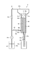
- FIG. 3 is a schematic configuration diagram illustrating a nozzle cleaning device that uses the nozzle cleaning method according to the first embodiment of the present invention.
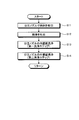
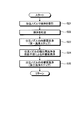
- FIG. 4 is a flowchart of the nozzle cleaning operation according to the first embodiment of the present invention.
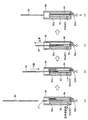
- FIG. 5 is an operation diagram showing a cleaning operation of the nozzle cleaning method according to the first exemplary embodiment of the present invention.
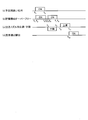
- FIG. 6 is a time chart showing the cleaning operation of the nozzle cleaning method according to the first exemplary embodiment of the present invention.
- FIG. 1 is a schematic configuration diagram showing an automatic analyzer using a nozzle cleaning method according to an embodiment of the present invention.
- FIG. 2 is a schematic configuration diagram showing the dispensing apparatus.
- FIG. 3 is a schematic configuration diagram illustrating a nozzle cleaning device that uses the nozzle cleaning method according to the
- FIG. 7 is a schematic block diagram which shows the nozzle cleaning apparatus which uses the nozzle cleaning method concerning Embodiment 2 of this invention.
- FIG. 8 is a flowchart of the nozzle cleaning operation according to the second embodiment of the present invention.
- FIG. 9 is an operation diagram showing a cleaning operation of the nozzle cleaning method according to the second exemplary embodiment of the present invention.
- FIG. 10 is a time chart showing the cleaning operation of the nozzle cleaning method according to the second embodiment of the present invention.
- FIG. 1 is a schematic configuration diagram showing an automatic analyzer using a nozzle cleaning method according to an embodiment of the present invention.
- the automatic analyzer 1 controls a measurement mechanism 9 that measures light passing through a reaction product between a specimen and a reagent, and the entire automatic analyzer 1 including the measurement mechanism 9.
- the automatic analyzer 1 automatically performs analysis of a plurality of samples by cooperation of these two mechanisms.
- the measurement mechanism 9 is roughly divided into a specimen table 2, a reaction table 3, a reagent table 4, a specimen dispensing mechanism (sample dispensing apparatus) 5, a reagent dispensing mechanism (reagent dispensing apparatus) 7, and a nozzle cleaning.
- Mechanisms (nozzle cleaning devices) 6 and 8 are provided.
- the sample table 2 has a disk-like table and includes a plurality of storage units 21 arranged at equal intervals along the circumferential direction of the table. In each storage unit 21, a sample container 22 containing a sample is detachably stored. The sample container 22 has an opening 22a that opens upward.
- the sample table 2 is rotated in a direction indicated by an arrow in FIG. 1 by a sample table driving unit (not shown) with a vertical line passing through the center of the sample table 2 as a rotation axis.
- a sample table driving unit not shown
- the sample container 22 is transported to the sample aspirating position where the sample is aspirated by the sample dispensing mechanism 5.
- an identification label (not shown) having sample information relating to the type of sample contained and analysis items is attached to the sample container 22.
- the sample table 2 includes a reading unit 23 that reads information on the identification label of the sample container 22.
- the reaction table 3 has an annular table and includes a plurality of storage portions 31 arranged at equal intervals along the circumferential direction of the table.
- a transparent reaction container 32 for storing a sample and a reagent is detachably stored in a form opening upward.
- the reaction table 3 is rotated in a direction indicated by an arrow in FIG. 1 by a reaction table driving unit (not shown) with a vertical line passing through the center of the reaction table 3 as a rotation axis.
- the reaction container 32 is transported to the sample discharge position where the sample is discharged by the sample dispensing mechanism 5 or the reagent discharge position where the reagent is discharged by the reagent dispensing mechanism 7.
- the reaction table 3 is provided with a photometric device 33.
- the photometric device 33 includes a light source 33a and a light receiving unit 33b.
- the light source 33a emits analysis light having a predetermined wavelength.
- the light receiving unit 33b measures the light beam emitted from the light source 33a and transmitted through the reaction solution in which the sample and the reagent contained in the reaction container 32 have reacted.
- the light source 33a and the light receiving portion 33b are arranged at positions where they oppose each other in the radial direction with the storage portion 31 of the reaction table 3 interposed therebetween.
- the reaction table 3 includes a cleaning mechanism 34 that discharges the measured reaction solution from the reaction container 32 and cleans the reaction container 32.
- the reagent table 4 has a disk-shaped table and includes a plurality of storage portions 41 arranged at equal intervals along the circumferential direction of the table.
- a reagent container 42 storing a reagent is detachably stored in each storage unit 41.
- the reagent container 42 has an opening 42a that opens upward.
- the reagent table 4 is rotated in a direction indicated by an arrow in FIG. 1 by a reagent table driving unit (not shown) with a vertical line passing through the center of the reagent table 4 as a rotation axis.
- the reagent container 42 is transported to the reagent suction position where the reagent is sucked by the reagent dispensing mechanism 7.
- an identification label (not shown) having reagent information relating to the type and amount of reagent contained is affixed to the reagent container 42.
- the reagent table 4 includes a reading unit 43 that reads information on the identification label of the reagent container 42.
- the sample dispensing mechanism 5 has a dispensing nozzle for aspirating and discharging the sample attached to the distal end, and freely moves up and down in the vertical direction and rotates around the vertical line passing through its proximal end as a central axis.
- the sample dispensing mechanism 5 is provided between the sample table 2 and the reaction table 3, sucks the sample in the sample container 22 conveyed to the predetermined position by the sample table 2 with a dispensing nozzle, rotates the arm, The sample is dispensed into the reaction container 32 conveyed to a predetermined position by the reaction table 3, and the sample is transferred into the reaction container 32 on the reaction table 3 at a predetermined timing.
- the reagent dispensing mechanism 7 is provided with a dispensing nozzle for sucking and discharging the reagent at the distal end, and freely moves up and down in the vertical direction and rotates around the vertical line passing through its base end as a central axis. Provide an arm.
- the reagent dispensing mechanism 7 is provided between the reagent table 4 and the reaction table 3.
- the reagent in the reagent container 42 transported to a predetermined position by the reagent table 4 is sucked by the dispensing nozzle, the arm is swung,
- the reagent is dispensed into the reaction container 32 transported to a predetermined position by the reaction table 3, and the reagent is transferred into the reaction container 32 on the reaction table 3 at a predetermined timing.
- FIG. 2 shows a schematic configuration diagram of the specimen dispensing mechanism 5 (the same applies to the reagent dispensing mechanism 7).
- the sample dispensing mechanism 5 has a dispensing nozzle 50 as shown in FIG.
- the dispensing nozzle 50 is formed in a rod-like shape from stainless steel or the like, and the tip side has a tapered shape.
- the upper proximal end is attached to the distal end of the arm 51 with the distal end directed downward.
- the arm 51 is horizontally arranged, and its base end is fixed to the upper end of the support shaft 52.
- the support shaft 52 is vertically arranged and is rotated about the vertical axis O by the nozzle transfer unit 53.
- the arm 51 When the support shaft 52 rotates, the arm 51 turns in the horizontal direction and moves the dispensing nozzle 50 in the horizontal direction. Further, the support shaft 52 moves up and down along the vertical axis O by the nozzle transfer section 53. When the support shaft 52 moves up and down, the arm 51 moves up and down in the vertical direction, and the dispensing nozzle 50 moves up and down in the vertical (up and down) direction and in the longitudinal direction of the dispensing nozzle 50.
- the tube 54a is connected to the proximal end of the dispensing nozzle 50.
- the other end of the tube 54 a is connected to the syringe 55.
- the syringe 55 includes a cylindrical cylinder 55a to which the other end of the tube 54a is connected, and a plunger 55b provided so as to be able to advance and retreat in the cylinder 55a while sliding on the inner wall surface of the cylinder 55a.
- the plunger 55 b is connected to the plunger driving unit 56.
- the plunger drive unit 56 is configured using, for example, a linear motor, and moves the plunger 55b back and forth with respect to the cylinder 55a.
- One end of a tube 54b is connected to the cylinder 55a of the syringe 55.
- the other end of the tube 54b is connected to a tank 57 that stores the preload liquid L1. Further, an electromagnetic valve 58 and a pump 59 are connected in the middle of the tube 54b. An incompressible fluid such as distilled water or deaerated water is applied as the preload liquid L1. This preload liquid L1 is also applied as a cleaning liquid for cleaning the inside of the dispensing nozzle 50.
- the sample dispensing mechanism 5 drives the pump 59 and opens the electromagnetic valve 58 to fill the preloading liquid L1 accommodated in the tank 57 into the cylinder 55a of the syringe 55 through the tube 54b. Further, the cylinder 55a is filled up to the tip of the dispensing nozzle 50 through the tube 54a. In such a state that the preload liquid L1 is filled up to the tip of the dispensing nozzle 50, the electromagnetic valve 58 is closed and the pump 59 is stopped. When the specimen or reagent is aspirated, the plunger driving unit 56 is driven to move the plunger 55b backward relative to the cylinder 55a, so that the tip of the dispensing nozzle 50 is passed through the preload liquid L1.
- a suction pressure is applied, and the specimen and the reagent are sucked by this suction pressure.
- the tip of the dispensing nozzle 50 is driven via the preload liquid L1 by driving the plunger driving unit 56 and moving the plunger 55b to the cylinder 55a.
- a discharge pressure is applied to the part, and the specimen and the reagent are discharged by this discharge pressure.
- the sample dispensing mechanism 5 has a liquid level detection function for detecting the liquid level of the sample and reagent dispensed by the dispensing nozzle 50.
- the liquid level detection function for example, there is a function that detects the liquid level by a change in capacitance when the dispensing nozzle 50 comes into contact with a specimen or a sample.
- FIG. 3 shows a schematic configuration diagram of the nozzle cleaning mechanism.
- the nozzle cleaning mechanism 6 (also the nozzle cleaning mechanism 8) has a cleaning tank 60.
- the cleaning tank 60 is formed in a cylindrical shape, and has an opening 60a at the top so that the tip of the descending dispensing nozzle 50 is inserted from above.
- a prismatic or columnar storage tank 62 is provided in the central area of the cleaning tank 60.
- the storage tank 62 has an opening 62a at the top so that the tip of the dispensing nozzle 50 that descends is inserted from above, and a storage cleaning liquid supply means 63 is provided at the bottom of the side surface.
- the cleaning liquid supply means 63 for storage is connected to the storage tank 62 through the nozzle part 63 a, and the nozzle part 63 a is provided with the discharge port facing the inside of the storage tank 62.
- One end of a tube 63b is connected to the nozzle portion 63a, and the other end of the tube 63b is connected to a tank 61c that stores the cleaning liquid L2.
- an electromagnetic valve 63c and a pump 61e are connected in the middle of the tube 63b, and the tube 63b is connected from the nozzle portion 63a to the tank 61c via the electromagnetic valve 63c and the pump 61e.
- distilled water, degassed water, or the like is applied as the cleaning liquid L2.
- One end of the tube 62b is connected to the bottom of the storage tank 62, and the other end of the tube 62b is connected to the waste tank 62c via the electromagnetic valve 62d.
- the washing tank 60 is provided with an overflow tank 64.
- the overflow tank 64 is arranged alongside the storage tank 62 inside the cleaning tank 60.
- the opening of the overflow tank 64 is formed in a mortar shape so as to form a slope inclined downward from the opening 62 a of the storage tank 62, and the lower part is formed so as to penetrate the bottom of the cleaning tank 60.
- One end of a tube 64 a is connected to the lower part of the overflow tank 64.
- the other end of the tube 64a is connected to a waste tank 62c.
- the nozzle cleaning mechanism 6 supplies the cleaning liquid L2 stored in the tank 61c to the inside of the storage tank 62 from the discharge port of the nozzle portion 63a through the tube 63b by driving the pump 61e with the electromagnetic valve 63c opened. And stored in the storage tank 62.
- the cleaning liquid L ⁇ b> 2 that is supplied from the nozzle part 63 a to the inside of the storage tank 62 and overflows from the opening 62 a flows into the overflow tank 64 from the cleaning tank 62 along the slope formed between the storage tank 62 and the overflow tank 64. It is guided and discharged from the overflow tank 64 through the tube 64a to a waste tank 62c outside the cleaning tank 60.
- the cleaning liquid L2 stored in the storage tank 62 by opening the electromagnetic valve 62d is discharged to the waste tank 62c through the tube 62b.
- the sample dispensing mechanism 5 dispenses a sample from the sample container 22 to the reaction container 32.
- the reagent dispensing mechanism 7 dispenses a reagent from the reagent container 42 into the reaction container 32.
- the reaction container 32 into which the sample and the reagent are dispensed reacts while the sample and the reagent are agitated while being conveyed along the circumferential direction by the reaction table 3, and passes between the light source 33 a and the light receiving unit 33 b. pass.
- the analysis light emitted from the light source 33a and passed through the reaction solution in the reaction vessel 32 is measured by the light receiving unit 33b and analyzed for component concentration and the like.
- the reaction vessel 32 is used for analysis of the specimen again after the measurement reaction solution is discharged and washed by the washing mechanism 34.
- the control mechanism 10 includes a control unit 101, an input unit 102, an analysis unit 103, a storage unit 104, an output unit 105, and a transmission / reception unit 107.
- Each unit included in the control mechanism 10 is electrically connected to the control unit 101.
- the analysis unit 103 is connected to the photometric device 33 via the control unit 101, analyzes the component concentration of the sample based on the amount of light received by the light receiving unit 33 b, and outputs the analysis result to the control unit 101.
- the input unit 102 is a part that performs an operation of inputting an inspection item or the like to the control unit 101. For example, a keyboard or a mouse is used.
- the storage unit 104 is configured by using a hard disk that magnetically stores information and a memory that loads various programs related to the process from the hard disk and electrically stores them when the automatic analyzer 1 executes the process. Various information including the analysis result of the specimen is stored.
- the storage unit 104 may include an auxiliary storage device that can read information stored in a storage medium such as a CD-ROM, a DVD-ROM, or a PC card.
- the output unit 105 is configured using a printer, a speaker, and the like, and outputs various information related to analysis under the control of the control unit 101.
- the output unit 105 includes a display unit 106 configured using a display or the like.
- the display unit 106 displays analysis contents, alarms, and the like, and a display panel or the like is used.
- the input unit 102 and the display unit 106 may be realized by a touch panel.
- the transmission / reception unit 107 has a function as an interface for performing transmission / reception of information according to a predetermined format via a communication network (not shown).
- control unit 101 is connected to the nozzle transfer unit 53, the plunger drive unit 56, the electromagnetic valve 58, and the pump 59 of the sample dispensing mechanism 5 (same as the reagent dispensing mechanism 7) described above.
- a pump 61e and solenoid valves 63c and 62d of the nozzle cleaning mechanism 6 (same for the nozzle cleaning mechanism 8) are connected.
- the control mechanism 10 controls operation processing of the sample dispensing mechanism 5, the reagent dispensing mechanism 7, and the nozzle cleaning mechanisms 6 and 8 using various programs related to each process of the automatic analyzer 1.
- the reagent dispensing mechanism 7 dispenses the reagent from the reagent container 42 into the plurality of reaction containers 32 conveyed along the circumferential direction by the rotating reaction table 3.
- the reaction container 32 into which the reagent has been dispensed is transported along the circumferential direction by the reaction table 3, and the specimen is dispensed from the specimen container 22 held on the specimen table 2 by the specimen dispensing mechanism 5.
- the dispensing nozzle after the reagent and sample dispensing is cleaned by the nozzle cleaning mechanisms 6 and 8 before the next reagent and sample dispensing in order to prevent carryover.
- FIG. 4 is a flowchart showing the cleaning operation of the dispensing nozzle
- FIG. 5 is an operation diagram showing the cleaning operation of the nozzle cleaning mechanism.
- the control unit 101 first moves the dispensing nozzle 50 above the opening 22a of the sample container 22 at the sample aspirating position, and sucks the sample with the dispensing nozzle 50 (step S11). .
- the control unit 101 moves the dispensing nozzle 50 above the reaction container 32 at the sample discharge position, and discharges the sample (step S12).
- the control unit 101 moves the dispensing nozzle 50 above the opening 62a of the storage tank 62 in the cleaning tank 60 of the nozzle cleaning mechanism 6 to overflow the cleaning liquid L2 supplied by the storage cleaning liquid supply means 63.
- a first cleaning step (step S13) is performed to clean the inner wall surface of the dispensing nozzle 50 where the specimen remains by discharging the preload liquid L1.
- a second cleaning step is performed in which the dispensing nozzle 50 is dipped in the storage tank 62 overflowing the cleaning liquid L2 to clean at least the outer wall surface (step S14).
- step S13 first, as shown in FIG. 5A, the control unit 101 supplies the cleaning liquid L2 by the storage cleaning liquid supply means 63 connected to the lower side of the side surface of the storage tank 62, and opens the opening.
- the plunger driving section 56 is driven to move the plunger 55b relative to the cylinder 55a, whereby the preload liquid L1 is transferred to the dispensing nozzle 50.
- the sample is discharged together with the remaining specimen.
- the specimen is removed from the dispensing nozzle 50 by discharging the preload liquid L1, and the inner wall surface is washed.
- the cleaning liquid L2 supplied by the storage cleaning liquid supply means 63 overflows from the opening 62a to the adjacent overflow tank 64. Therefore, the preload liquid L1 containing the specimen is forcibly discharged to the overflow tank 64 together with the overflowing cleaning liquid L2.
- the cleaning liquid L2 in the storage tank 62 overflows, so that the sample does not enter the cleaning liquid L2 in the storage tank 62, and the clean cleaning liquid L2 is used.
- the cleaning time of the outer wall surface of the dispensing nozzle 50 performed after the first cleaning step can be shortened compared with the case of cleaning with the cleaning liquid L2 mixed with the specimen.
- the cleaning liquid L2 overflowed from the storage tank 62 is guided to the overflow tank 64 along the slope formed between the storage tank 62 and the overflow tank 64, and passes through the tube 64a connected to the overflow tank 64 to the waste tank. 62c is discarded.
- step S14 the control unit 101 overflows the cleaning liquid L2 supplied by the storage cleaning liquid supply means 63 connected to the lower side of the side surface of the storage tank 62 via the nozzle part 63a. Then, the dispensing nozzle 50 in which the specimen remains on the outer wall surface is lowered and immersed by the nozzle transfer unit 53. When the tip of the dispensing nozzle 50 with the specimen attached to the outer wall surface is dipped in the cleaning liquid L2 in the storage tank 62, the storage cleaning liquid supply means 63 supplies the storage tank 62 with the cleaning liquid supply means 63 at the opening 62a.
- the specimen washed from the outer wall surface of the dispensing nozzle 50 by the dipping immersion of the dispensing nozzle 50 into the washing liquid L2 is immediately after washing from the dispensing nozzle 50.
- the overflow is forcedly overflowed into the overflow tank 64 together with the cleaning liquid L2. Since the wall surface between the storage tank 62 and the overflow tank 64 has a shape that forms a slope inclined downward from the storage tank 62 to the overflow tank 64, overflow is easily performed.
- the sample adhering to the dispensing nozzle 50 is washed with the cleaning liquid L2 in the storage tank 62 and then overflowed together with the cleaning liquid L2 without being diffused. be able to. Since the cleaning liquid L2 containing the removed specimen is discharged without staying in the storage tank 62, the clean cleaning liquid L2 is stored in the storage tank 62, and the dirty cleaning liquid L2 is reattached to the dispensing nozzle 50. In this case, the cleaning time can be shortened.
- the nozzle cleaning method may be set so that the cleaning of the outer wall surface is completed within the time required for the dispensing nozzle 50 to descend into the storage tank 62. After the end of the descent, the outer wall surface may be further cleaned by continuing to immerse the dispensing nozzle 50 in the storage tank 62.
- the cleaning liquid L2 overflowed from the storage tank 62 is guided to the overflow tank 64, and is discarded to the disposal tank 62c through the tube 64a connected to the overflow tank 64.
- the depth of insertion into the storage tank 62 of the dispensing nozzle 50 may be greater than the depth at which the dispensing nozzle 50 is submerged in the sample or the like when the sample or reagent is aspirated, and is selected and determined based on the analysis information. Is done.
- the analysis information is stored in the storage unit 104 in association with the sample container 22 placed on the sample table 2.
- the penetration depth of the dispensing nozzle 50 when aspirating a serum sample or reagent is about several millimeters (for example, 3 mm) from the tip of the nozzle.
- the depth (for example, a depth corresponding to the total depth of the sample) Therefore, it is set so that the dispensing nozzle 50 is inserted into the storage tank 62 at a depth greater than the depth at which the dispensing nozzle 50 is submerged during the suction.
- the tip position of the dispensing nozzle 50 when the dispensing nozzle 50 is inserted into the storage tank 62 is the nozzle portion from the storage cleaning liquid supply means 63. It shall be located above the connection part of 63a.
- the cleaning liquid L2 is supplied from the storage cleaning liquid supply means 63 even when the specimen remains on the outer wall surface of the dispensing nozzle 50.
- the inside of the storage tank 62 can be kept clean.
- the supply of the cleaning liquid L2 from the storage cleaning liquid supply means 63 is stopped, and the overflow of the cleaning liquid L2 in the storage tank 62 is also stopped.
- the cleaning liquid L2 that is discarded can be reduced.
- the dispensing nozzle 50 is raised by the nozzle transfer unit 53 and pulled up from the storage tank 62. By adjusting the rising speed of the dispensing nozzle 50, the amount of the cleaning liquid L2 attached to the dispensing nozzle 50 can be reduced.
- the cleaning liquid L2 stored in the storage unit 62 by opening the electromagnetic valve 62d is passed through the tube 62b to the waste tank. Discharge to 62c.
- the plunger nozzle 56b is moved backward with respect to the cylinder 55a by driving the plunger driving unit 56 while immersing the dispensing nozzle 50 in the storage tank 62 and washing the outer wall surface. By moving and moving forward, it is possible to cause the dispensing nozzle 50 to suck and discharge the cleaning liquid L2 in the storage tank 62 to further clean the inner wall surface of the dispensing nozzle 50.
- the overflow of the storage tank 62 is stopped before the dispensing nozzle 50 shown in FIG. 5C is raised, but the overflow is continued by supplying the cleaning liquid L2 from the storage cleaning liquid supply means 63. You may continue to let them.
- FIG. 6 is a time chart of the cleaning operation of the nozzle cleaning mechanism using the present invention.
- the dispensing nozzle 50 that has discharged the specimen or reagent into the reaction container 32 stored in the storage unit 31 of the reaction table 3 is transferred to the upper part of the storage tank 62 of the nozzle cleaning mechanism 6 or 8 by the nozzle transfer unit 53.
- the plunger driving unit 56 is driven to move the plunger 55b to the cylinder 55a so that the preloading liquid L1 is dispensed.
- the sample remaining in the dispensing nozzle 50 are discharged from the dispensing nozzle 50 (t1). At this time, as shown in FIG.
- the storage tank 62 starts when the plunger pre-pressurizing liquid L1 reaches the storage tank 62 from t1 when the plunger driving section 56 is driven.
- the cleaning liquid L2 is supplied from at least the storage cleaning liquid supply means 63, and the overflow tank 64 passes from the opening 62a of the storage tank 62 along the slope formed between the storage tank 62 and the overflow tank 64. Is controlled by the control unit 101 to overflow.
- the control unit 101 stops the discharge of the preload liquid L1 by stopping the driving of the plunger driving unit 56 (t3), and the overflow of the storage tank 62 is also discharged accordingly.
- the preload liquid L1 is stopped after reaching the storage tank 62 (t4). While the preload liquid L1 containing the specimen is discharged from the dispensing nozzle 50 and introduced into the storage tank 62, at least the storage tank 62 is controlled to overflow by the supply of the cleaning liquid L2 from the storage cleaning liquid supply means 63. Is done. Thereby, it is possible to prevent the sample from being mixed into the cleaning liquid L2 in the storage tank 62.
- the dispensing nozzle 50 is lowered and immersed in the storage tank 62 by the nozzle transfer portion 53 (t5).
- the storage tank 62 is at the time t6 when the tip of the dispensing nozzle 50 is immersed in the cleaning liquid L2 in the storage tank 62 from t5 when the nozzle transfer unit 53 is driven.
- at least the cleaning liquid L2 is supplied from the storage cleaning liquid supply means 63 and is controlled to overflow at the opening 62a of the storage tank 62.
- the dispensing nozzle 50 starts to be lifted from the storage tank 62 by driving the nozzle transfer section 53 (t9), and the lifting of the dispensing nozzle 50 is completed at t11.
- the cleaning liquid L2 in the storage tank 62 rises in the vertical direction by the nozzle transfer section 53, and after the time t10 when the storage tank 62 is pulled up from the cleaning liquid L2. Then, the electromagnetic valve 62d is opened to be discharged to the waste tank 62c.
- the dispensing nozzle can be cleaned in a single storage tank, the cleaning time can be shortened, and the sample can be brought into the storage tank. It can reduce and can perform efficient washing
- the cleaning tank of this embodiment is composed of a single storage tank and an overflow tank that discharges the cleaning liquid overflowing from the storage tank, and there is no need to provide extra equipment such as a disposal tank, thereby simplifying the cleaning mechanism and thereby There is an advantage that the cost can be reduced.
- the storage tank 62 may be continuously overflowed by continuously supplying the cleaning liquid L2 from the storage cleaning liquid supply means 63 through the first cleaning step and the second cleaning step.
- the discharge of the cleaning liquid L2 stored in the storage unit 62 shown in FIG. 5D to the waste tank 62c is omitted, and the dispensing nozzle 50 is subsequently cleaned.
- the cleaning liquid L2 is supplied from the storage cleaning liquid supply means 63 through the first cleaning step and the second cleaning step to overflow the storage tank 62, and the dispensing shown in FIG.
- the supply of the cleaning liquid L2 from the storage cleaning liquid supply means 63 may be stopped before the nozzle 50 is raised, and the dispensing nozzle 50 may be pulled up from the storage tank 62 by the nozzle transfer unit 53 after the overflow is stopped. Thereafter, the cleaning liquid L2 in the storage tank 62 shown in FIG. 5 (d) is discharged to the waste tank 62c, and the dispensing nozzle 50 is newly cleaned.
- This method is preferable because the amount of the cleaning agent L2 used can be reduced while keeping the cleanliness of the cleaning agent L2 in the storage tank 62 higher.
- the second embodiment is different from the first embodiment in that an ejection cleaning liquid supply means 61 is installed above the storage tank 62 and the overflow tank 64 in the cleaning tank 60.
- FIG. 7 is a schematic configuration diagram of the nozzle cleaning apparatus of the present embodiment
- FIG. 8 is a flowchart showing the cleaning operation
- FIG. 9 is an operation diagram showing the cleaning operation.
- the cleaning tank 60 of the nozzle cleaning apparatus of the present embodiment is provided with jetting cleaning liquid supply means 61.
- the jetting cleaning liquid supply means 61 has a nozzle part 61 a, which is arranged at the upper part in the cleaning tank 60, has its discharge port directed obliquely downward, and the vertical center line S of the cleaning tank 60.
- a plurality of (two in the present embodiment) are provided.
- One end of the tube 61b is connected to each nozzle portion 61a.
- the tube 61b is formed by joining together on the way from one end to the other end.
- the other end of the tube 61b is connected to a tank 61c that stores the cleaning liquid L2.
- An electromagnetic valve 61d and a pump 61e are connected to the middle of the tube 61b joined together.
- a storage tank 62 and an overflow tank 64 are provided inside the cleaning tank 60 and below the nozzle portion 61a, and a tube 62b and an electromagnetic valve 62d are installed at the bottom of the storage tank 62.
- the storage cleaning liquid supply means 63 is provided in the same manner as in the first embodiment.
- the cleaning liquid L2 stored in the tank 61c is ejected from the discharge port of the nozzle portion 61a into the cleaning tank 60 through the tube 61b. Is done. Further, by driving the pump 61e with the electromagnetic valve 63c opened, the cleaning liquid L2 stored in the tank 61c is supplied to the inside of the storage tank 62 from the discharge port of the nozzle portion 63a via the tube 63b and stored. It is stored inside the tank 62.
- the wall surface between the storage tank 62 and the overflow tank 64 has a shape that forms a slope that slopes downward from the storage tank 62 to the overflow tank 64, the cleaning liquid L2 flows into the overflow tank 64 along the slope from the opening 62a. Led to.
- the overflowing cleaning liquid L2 and the like are discharged from the overflow tank 64 through the tube 64a to a waste tank 62c outside the cleaning tank 60.
- the cleaning liquid L2 stored in the storage part 62 by opening the electromagnetic valve 62d is discharged to the waste tank 62c through the tube 62b.
- steps S21, S22, S23, and S25 are the same as those in the first embodiment, but the storage liquid L2 overflowed between steps S23 and S25.
- a step of cleaning the outer wall surface by letting the dispensing nozzle 50 enter and descend into the flow path in which the cleaning liquid L2 is jetted by the jet cleaning liquid supply means 61 (step S24).
- the inner wall surface of the dispensing nozzle 50 is washed by discharging the preload liquid L1 (step S23), and from the nozzle portion 61a of the ejection washing liquid supply means 61 on the storage tank 62 overflowing the washing liquid L2.
- the dispensing nozzle 50 is moved down into the flow path from which the cleaning liquid L2 has been ejected to clean the outer wall surface (step S24).
- the dispensing nozzle 50 is continuously dipped into the storage tank 62 overflowing the cleaning liquid L2, and at least the outer wall surface is cleaned (step S25).
- step S23 first, as shown in FIG. 9A, the control unit 101 supplies the cleaning liquid L2 by the storage cleaning liquid supply means 63 connected to the lower side of the side surface of the storage tank 62, and opens the opening.
- the plunger driving section 56 is driven to move the plunger 55b relative to the cylinder 55a, whereby the preload liquid L1 is transferred to the dispensing nozzle 50.
- the sample is discharged together with the remaining specimen.
- the specimen is removed from the dispensing nozzle 50 by discharging the preload liquid L1, and the inner wall surface is washed.
- the cleaning liquid L2 supplied by the storage cleaning liquid supply means 63 overflows from the opening 62a to the adjacent overflow tank 64. Therefore, the preload liquid L1 containing the specimen is forcibly discharged to the overflow tank 64 together with the overflowing cleaning liquid L2.
- the cleaning liquid L2 in the storage tank 62 overflows, so that the sample does not enter the cleaning liquid L2 in the storage tank 62, and the clean cleaning liquid L2 is used. Subsequent immersion cleaning is possible.
- the cleaning liquid L2 overflowed from the storage tank 62 is guided to the overflow tank 64, and is discarded to the disposal tank 62c through the tube 64a connected to the overflow tank 64.
- the control unit 101 ejects the cleaning liquid L2 from the nozzle portion 61a of the ejection cleaning liquid supply means 61 at the upper part of the storage tank 62 where the cleaning liquid L2 has overflowed.
- the dispensing nozzle 50 is moved down into the flow path, and the outer wall surface of the dispensing nozzle 50 is washed.
- the cleaning liquid L2 is supplied from the nozzle part 63a of the storage cleaning liquid supply means 63 to the storage part 62, and the cleaning liquid L2 overflows from the opening 62a of the storage tank 62 to the overflow tank 64.
- the dispensing nozzle 50 is lowered and inserted into the opening 60 a of the cleaning tank 60. Accordingly, the cleaning liquid L2 ejected from the nozzle portion 61a collides with the outer wall surface of the dispensing nozzle 50 along the longitudinal direction (entry direction) of the dispensing nozzle 50 and adheres to the outer wall surface of the dispensing nozzle 50.
- the removed specimen is removed and the outer wall surface of the dispensing nozzle 50 is washed. Although the removed specimen falls into the storage tank 62 together with the cleaning liquid L2, since the storage tank 62 overflows the cleaning liquid L2 from the opening 62a, the removed specimen is discharged into the overflow tank 64 together with the overflowing cleaning liquid L2. Is done.
- the cleaning liquid L2 overflows into the overflow tank 64, the specimen removed by jetting the cleaning liquid L2 from the nozzle section 61a, and the specimen cleaned from the outer wall surface by immersion in the cleaning liquid L2 in the storage tank 62 Is forcibly overflowed into the overflow tank 64 together with the cleaning liquid L2.
- the supply of the cleaning liquid L2 from the storage cleaning liquid supply means 63 is stopped, and the overflow of the cleaning liquid L2 in the storage tank 62 is also stopped.
- the dispensing nozzle 50 is raised by the nozzle transfer unit 53 and pulled up from the storage tank 62.
- the cleaning liquid L2 stored in the storage section 62 by opening the electromagnetic valve 62d is passed through the tube 62b to the waste tank. It is discharged to 62c.
- FIG. 10 is a time chart of the cleaning operation of the nozzle cleaning mechanism of this embodiment.
- the dispensing nozzle 50 that has discharged the specimen or reagent into the reaction container 32 stored in the storage unit 31 of the reaction table 3 is transferred to the upper part of the storage tank 62 of the nozzle cleaning mechanism 6 or 8 by the nozzle transfer unit 53.
- the plunger driving unit 56 is driven to move the plunger 55b forward relative to the cylinder 55a, whereby the preloading liquid L1 is dispensed.
- the sample remaining in the dispensing nozzle 50 are discharged from the dispensing nozzle 50 (t1). At this time, as shown in FIG.
- the storage tank 62 reaches the storage tank 62 after the pre-driving liquid L1 after driving the plunger drive section 56 from t1 when the plunger drive section 56 is driven.
- the time t2 at least the cleaning liquid L2 is supplied from the storage cleaning liquid supply means 63, and the overflow tank is opened from the opening 62a of the storage tank 62 along the slope formed between the storage tank 62 and the overflow tank 64. It is controlled by the control unit 101 to overflow to 64.
- the control unit 101 stops the plunger driving unit 56 (t3), and accordingly, the overflow of the storage tank 62 also reaches the storage tank 62 of the discharged preload liquid L1. It is stopped after completion (t4). While the preload liquid L1 containing the specimen is discharged from the dispensing nozzle 50 and introduced into the storage tank 62, at least the storage tank 62 is controlled to overflow by the supply of the cleaning liquid L2 from the storage cleaning liquid supply means 63. Is done. Thereby, it is possible to prevent the sample from being mixed into the cleaning liquid L2 in the storage tank 62.
- the dispensing nozzle 50 is moved by the nozzle transfer section 53 in the flow path in which the cleaning liquid L2 is jetted by the jet cleaning liquid supply means 61 at the upper part of the cleaning tank 60. Lowering approach is entered (t5).
- the storage tank 62 ejects the cleaning liquid L2 by the ejection cleaning liquid supply means 61 (t5), and the cleaning liquid L2 is applied to the outer wall surface of the dispensing nozzle 50.
- the specimen that has collided and adhered to the dispensing nozzle 50 is removed, and at least t6, which is the time when the cleaning liquid L2 containing the specimen reaches the storage tank 62, reaches at least the cleaning liquid L2 from the storage cleaning liquid supply means 63. It is supplied and controlled to overflow at the opening 62 a of the storage tank 62.
- the dispensing nozzle 50 is dipped in the storage tank 62 while descending and entering the flow path in which the cleaning liquid L2 is sprayed by the nozzle portion 61a. While the dispensing nozzle 50 is lowered by the nozzle transfer unit 53, at least the storage tank 62 is controlled to overflow by the supply of the cleaning liquid L2 from the storage cleaning liquid supply means 63.
- the dispensing nozzle 50 starts to be pulled up from the storage tank 62 by driving the nozzle transfer unit 53 (t10), and the dispensing nozzle is completely lifted at t12.
- the cleaning liquid L2 in the storage tank 62 rises in the vertical direction from the dispensing nozzle 50 by the nozzle transfer section 53, and after the time t11 when the storage tank 62 is pulled up from the cleaning liquid L2.
- the electromagnetic valve 62d is opened to be discharged to the waste tank 62c.
- the nozzle cleaning method and the nozzle cleaning apparatus for cleaning the dispensing nozzle for sucking and discharging the liquid according to the present invention optically measure the reaction product of the sample and the reagent and analyze the components of the sample. Useful in analyzers.
Landscapes
- Engineering & Computer Science (AREA)
- Mechanical Engineering (AREA)
- Physics & Mathematics (AREA)
- Health & Medical Sciences (AREA)
- Life Sciences & Earth Sciences (AREA)
- Chemical & Material Sciences (AREA)
- Analytical Chemistry (AREA)
- Biochemistry (AREA)
- General Health & Medical Sciences (AREA)
- General Physics & Mathematics (AREA)
- Immunology (AREA)
- Pathology (AREA)
- Automatic Analysis And Handling Materials Therefor (AREA)
- Cleaning In General (AREA)
- Cleaning By Liquid Or Steam (AREA)
Abstract
分注ノズルの洗浄を確実に行うとともに、洗浄時間の短縮を可能とするノズル洗浄方法およびノズル洗浄装置を提供する。この目的のために、液体の吸引および吐出を行う分注ノズル(50)を洗浄するノズル洗浄方法において、分注終了後、洗浄液(L2)をオーバーフローさせた貯留槽(62)上部において、分注ノズル(50)の内壁面を予圧用液(L1)の吐出により洗浄する第一洗浄ステップと、洗浄液(L2)をオーバーフローさせた貯留槽(62)に、分注ノズル(50)を下降浸漬させることにより、少なくとも外壁面を洗浄する第二洗浄ステップと、を含む。
Description
本発明は、液体の吸引および吐出を行う分注ノズルを洗浄するノズル洗浄方法およびノズル洗浄装置に関するものである。
従来、血液や尿などの検体を分析する自動分析装置では、先に分注した検体が分注ノズルに付着したまま次に分注する検体に持ち越されることで、分析結果に影響を及ぼすキャリーオーバーを回避するため、分注ノズルを洗浄するノズル洗浄装置を備えている。このノズル洗浄装置は、検体を吸引する位置と検体を吐出する位置との間の分注ノズルの移動軌跡の途中に配置され、分注ノズルに対して洗浄液を供給するように構成されている。このノズル洗浄装置を用いたノズル洗浄方法では、検体の吸引および吐出を行って分注が完了した後に、分注ノズルをノズル洗浄装置の位置に移動させ、この分注ノズルに対して洗浄液を供給して分注ノズルを洗浄している。
ところで、分注後のノズル内には少量の検体が残留しており、洗浄液を貯留した洗浄装置内で分注ノズルを洗浄すると、洗浄液が分注ノズルに残留する検体により汚れてしまうため、キャリーオーバーの要求レベルが高くなると洗浄処理に多量の洗浄液を必要とすると共に、洗浄時間も長くなる。これを改善するために、洗浄槽に隣接して廃棄槽を設置して、残留検体を廃棄槽に廃棄後、洗浄する方法が提案されている(例えば、特許文献1参照)。
しかしながら、分注ノズルを廃棄槽と洗浄槽の2ケ所で所定の動作をさせるため、洗浄時間に分注ノズルの昇降動作に要する時間および廃棄槽から洗浄槽への移動時間が加算され、洗浄槽のみで洗浄動作を行なうよりも洗浄時間を多く要することとなり、高速化および処理能力の向上が要求される自動分析装置への2槽式の洗浄装置の適用は効率的ではない。
本発明は、上記に鑑みてなされたものであって、分注ノズルの洗浄を確実に行うとともに、洗浄時間の短縮を可能とするノズル洗浄方法およびノズル洗浄装置を提供することを目的とする。
上述した課題を解決し、目的を達成するために、本発明にかかる液体の吸引および吐出を行う分注ノズルのノズル洗浄方法は、分注終了後、洗浄液をオーバーフローさせた貯留槽上部において、前記分注ノズルの内壁面を予圧用液の吐出により洗浄する第一洗浄ステップと、洗浄液をオーバーフローさせた前記貯留槽に、前記分注ノズルを下降浸漬させることにより、少なくとも外壁面を洗浄する第二洗浄ステップとを含むことを特徴とする。
また、本発明に係るノズル洗浄方法は、上記の発明において、前記第一洗浄ステップにおける前記貯留槽のオーバーフローは、前記分注ノズルから内壁面洗浄用に吐出された予圧用液が前記貯留槽に落下到達前、または落下到達時、または落下到達後瞬時に開始されることを特徴とする。
また、本発明に係るノズル洗浄方法は、上記の発明において、前記第一洗浄ステップにおける前記貯留槽のオーバーフローは、前記分注ノズルから内壁面洗浄用の予圧用液の吐出終了後、吐出された前記予圧用液が前記貯留槽に落下到達後に停止されることを特徴とする。
また、本発明に係るノズル洗浄方法は、上記の発明において、前記第二洗浄ステップにおける前記貯留槽のオーバーフローは、前記分注ノズルが下降し、前記分注ノズルの先端が前記貯留槽に浸漬前に再開されることを特徴とする。
また、本発明に係るノズル洗浄方法は、上記の発明において、前記第二洗浄ステップにおける前記貯留槽のオーバーフローは、前記分注ノズルの前記貯留槽からの引上げ前に停止されることを特徴とする。
また、本発明に係るノズル洗浄方法は、上記の発明において、前記第二洗浄ステップ終了後であって、前記分注ノズル上昇による前記貯留槽からの引上げ後、前記貯留槽に貯留されている洗浄液を排出させることを特徴とする。
また、本発明に係るノズル洗浄方法は、上記の発明において、前記第一洗浄ステップおよび前記第二洗浄ステップにおいて、前記貯留槽からオーバーフローされた洗浄液をオーバーフロー槽にて排出することを特徴とする。
また、本発明に係るノズル洗浄方法は、上記の発明において、前記第二洗浄ステップ前に、洗浄液をオーバーフローさせた前記貯留槽上部にて噴出用洗浄液供給手段により洗浄液を噴出させた流路中に前記分注ノズルを下降進入させることを特徴とする。
また、本発明に係る液体の吸引および吐出を行なう分注ノズルのノズル洗浄装置は、前記分注ノズルが挿入される開口部を上部に有し、洗浄液をオーバーフローさせる貯留槽と、前記貯留槽からオーバーフローされた洗浄液を排出するオーバーフロー槽と、前記貯留槽に対して洗浄液を供給する貯留用洗浄液供給手段と、前記分注ノズルから内壁面洗浄用に吐出された予圧用液が前記貯留槽に落下到達時および前記分注ノズルの先端が前記貯留槽に浸漬開始時に少なくとも前記貯留槽をオーバーフロー状態に制御する制御手段と、を備えたことを特徴とする。
また、本発明に係る液体の吸引および吐出を行う分注ノズルのノズル洗浄装置は、上記の発明において、前記オーバーフロー槽の開口部は、貯留槽の開口部から下方に傾斜する斜面をなすように形成されることを特徴とする。
また、本発明に係る液体の吸引および吐出を行う分注ノズルのノズル洗浄装置は、上記の発明において、前記制御手段は、前記分注ノズルから内壁面洗浄用に吐出された予圧用液が前記貯留槽に落下到達前にオーバーフローを開始し、前記分注ノズルから内壁面洗浄用の予圧用液の吐出終了後、吐出された前記予圧用液が前記貯留槽に落下到達後にオーバーフローを停止させる制御を行うことを特徴とする。
また、本発明に係る液体の吸引および吐出を行う分注ノズルのノズル洗浄装置は、上記の発明において、前記制御手段は、前記分注ノズルが下降開始し、前記分注ノズルの先端が前記貯留槽に浸漬前にオーバーフローを再開し、前記分注ノズルの前記貯留槽からの引上げ前にオーバーフローを停止させる制御を行うことを特徴とする。
また、本発明に係る液体の吸引および吐出を行う分注ノズルのノズル洗浄装置は、上記の発明において、前記貯留槽上部領域内で洗浄液を噴出させる噴出用洗浄液供給手段を備え、前記制御手段は、前記噴出用洗浄液供給手段により噴出させた洗浄液が前記貯留槽に落下時に少なくとも前記貯留槽をオーバーフロー状態にする制御を行うことを特徴とする。
本発明にかかるノズル洗浄方法は、分注ノズルから内壁面洗浄用に残留検体と共に吐出された予圧用液が貯留槽に貯留された洗浄液に混入する際、および外壁面に検体が残留する分注ノズルが、洗浄液が貯留された前記貯留槽に下降浸漬する際に、前記貯留槽に貯留されている洗浄液をオーバーフローさせることにより、検体を含む予圧用液等を貯留槽内の洗浄液とともに強制的にオーバーフロー槽に排出することにより、分注ノズルの単一の貯留槽での洗浄を可能として洗浄時間の短縮を可能とすることができるとともに、前記貯留槽への検体の持込みを低減して効率的な洗浄を行なうことができる。
1 自動分析装置
2 検体テーブル
21、31、41 収納部
22 検体容器
22a、42a 開口部
23、43 読取部
3 反応テーブル
32 反応容器
33 測光装置
33a 光源
33b 受光部
34 洗浄機構
4 試薬テーブル
42 試薬容器
5 検体分注機構
7 試薬分注機構
50 分注ノズル
51 アーム
52 支軸
53 ノズル移送部
54a、54b チューブ
55 シリンジ
55a シリンダー
55b プランジャー
56 プランジャー駆動部
57 タンク
58 電磁弁
59 ポンプ
6、8 ノズル洗浄機構
60 洗浄槽
60a 開口部
61 噴出用洗浄液供給手段
61a ノズル部
61b、62b、63b、64a チューブ
61c タンク
61d、62d、63c 電磁弁
61e ポンプ
62 貯留槽
62a 開口部
62c 廃棄タンク
63 貯留用洗浄液供給手段
63a ノズル部
64 オーバーフロー槽
9 測定機構
10 制御機構
101 制御部
102 入力部
103 分析部
104 記憶部
105 出力部
106 表示部
107 送受信部
L1 予圧用液
L2 洗浄液
O 鉛直軸
S 中心線
以下に添付図面を参照して、本発明にかかるノズル洗浄方法およびノズル洗浄装置の好適な実施の形態を詳細に説明する。なお、この実施の形態により本発明が限定されるものではない。また、図面の記載において、同一部分には同一の符号を付している。
(実施の形態1)
図1は、本発明の実施の形態にかかるノズル洗浄方法を使用する自動分析装置を示す概略構成図である。図1に示すように、自動分析装置1は、検体と試薬との間の反応物を通過する光を測定する測定機構9と、測定機構9を含む自動分析装置1全体の制御を行なうとともに、測定機構9における測定結果の分析を行なう制御機構10とを備える。自動分析装置1は、これらの二つの機構が連携することによって複数の検体の分析を自動的に行なう。
図1は、本発明の実施の形態にかかるノズル洗浄方法を使用する自動分析装置を示す概略構成図である。図1に示すように、自動分析装置1は、検体と試薬との間の反応物を通過する光を測定する測定機構9と、測定機構9を含む自動分析装置1全体の制御を行なうとともに、測定機構9における測定結果の分析を行なう制御機構10とを備える。自動分析装置1は、これらの二つの機構が連携することによって複数の検体の分析を自動的に行なう。
まず、測定機構9について説明する。測定機構9は、大別して検体テーブル2と、反応テーブル3と、試薬テーブル4と、検体分注機構(検体分注装置)5と、試薬分注機構(試薬分注装置)7と、ノズル洗浄機構(ノズル洗浄装置)6および8とを備えている。
検体テーブル2は、円盤状のテーブルを有し、該テーブルの周方向に沿って等間隔で複数配置された収納部21を備えている。各収納部21には、検体を収容した検体容器22が着脱自在に収納される。検体容器22は、上方に向けて開口する開口部22aを有している。また、検体テーブル2は、検体テーブル2の中心を通る鉛直線を回転軸として検体テーブル駆動部(図示せず)によって図1に矢印で示す方向に回転する。検体テーブル2が回転すると検体容器22は、検体分注機構5によって検体が吸引される検体吸引位置に搬送される。
なお、検体容器22には、収容された検体の種類や分析項目に関する検体情報を有する識別ラベル(図示せず)が貼り付けてある。一方、検体テーブル2は、検体容器22の識別ラベルの情報を読み取る読取部23を備えている。
反応テーブル3は、円環状のテーブルを有し、該テーブルの周方向に沿って等間隔で複数配置された収納部31を備えている。各収納部31には、検体と試薬を収容する透明な反応容器32が上方に向けて開口した形態で着脱自在に収納される。また、反応テーブル3は、反応テーブル3の中心を通る鉛直線を回転軸として反応テーブル駆動部(図示せず)によって図1に矢印で示す方向に回転する。反応テーブル3が回転すると反応容器32は、検体分注機構5によって検体が吐出される検体吐出位置や、試薬分注機構7によって試薬が吐出される試薬吐出位置に搬送される。
また、反応テーブル3は、測光装置33を備えている。測光装置33は、光源33aおよび受光部33bを有している。光源33aは、所定波長の分析光を出射する。受光部33bは、光源33aから出射されて、反応容器32に収容された検体と試薬が反応した反応液を透過した光束を測定する。測光装置33は、前記光源33aと受光部33bが反応テーブル3の収納部31を挟んで半径方向に対向する位置に配置されている。なお、反応テーブル3は、測定後の反応液を反応容器32から排出し、該反応容器32を洗浄する洗浄機構34を備えている。
試薬テーブル4は、円盤状のテーブルを有し、該テーブルの周方向に沿って等間隔で複数配置された収納部41を備えている。各収納部41には、試薬を収容した試薬容器42が着脱自在に収納される。試薬容器42は、上方に向いて開口する開口部42aを有している。また、試薬テーブル4は、試薬テーブル4の中心を通る鉛直線を回転軸として試薬テーブル駆動部(図示せず)によって図1に矢印で示す方向に回転する。試薬テーブル4が回転すると試薬容器42は、試薬分注機構7によって試薬が吸引される試薬吸引位置に搬送される。
なお、試薬容器42には、収容された試薬の種類や収容量に関する試薬情報を有する識別ラベル(図示せず)が貼り付けてある。一方、試薬テーブル4は、試薬容器42の識別ラベルの情報を読み取る読取部43を備えている。
検体分注機構5は、検体の吸引および吐出を行なう分注ノズルが先端部に取り付けられ、鉛直方向への昇降および自身の基端部を通過する鉛直線を中心軸とする回転を自在に行なうアームを備える。検体分注機構5は、検体テーブル2と反応テーブル3との間に設けられ、検体テーブル2によって所定位置に搬送された検体容器22内の検体を分注ノズルによって吸引し、アームを旋回させ、反応テーブル3によって所定位置に搬送された反応容器32に分注して検体を所定タイミングで反応テーブル3上の反応容器32内に移送する。
試薬分注機構7は、試薬の吸引および吐出を行なう分注ノズルが先端部に取り付けられ、鉛直方向への昇降および自身の基端部を通過する鉛直線を中心軸とする回転を自在に行なうアームを備える。試薬分注機構7は、試薬テーブル4と反応テーブル3との間に設けられ、試薬テーブル4によって所定位置に搬送された試薬容器42内の試薬を分注ノズルによって吸引し、アームを旋回させ、反応テーブル3によって所定位置に搬送された反応容器32に分注して試薬を所定タイミングで反応テーブル3上の反応容器32内に移送する。
図2に検体分注機構5(試薬分注機構7も同様である)の概略構成図を示す。検体分注機構5は、図2に示すように分注ノズル50を有している。分注ノズル50は、ステンレスなどによって棒管状に形成されたもので、先端側はテーパー形状をとる。先端を下方に向けて上方の基端がアーム51の先端に取り付けてある。アーム51は、水平配置され、その基端が支軸52の上端に固定してある。支軸52は、鉛直配置されており、ノズル移送部53によって鉛直軸Oを中心として回転する。支軸52が回転すると、アーム51が水平方向に旋回して、分注ノズル50を水平方向に移動させる。また、支軸52は、ノズル移送部53によって鉛直軸Oに沿って昇降する。支軸52が昇降すると、アーム51が鉛直方向に昇降して、分注ノズル50を鉛直(上下)方向であって分注ノズル50の長手方向に昇降させる。
分注ノズル50の基端には、チューブ54aの一端が接続される。このチューブ54aの他端は、シリンジ55に接続される。シリンジ55は、チューブ54aの他端が接続された筒状のシリンダー55aと、シリンダー55aの内壁面に摺動しながらシリンダー55a内を進退可能に設けられたプランジャー55bとを有する。プランジャー55bは、プランジャー駆動部56に接続される。プランジャー駆動部56は、例えばリニアモーターを用いて構成され、シリンダー55aに対するプランジャー55bの進退移動を行うものである。シリンジ55のシリンダー55aには、チューブ54bの一端が接続される。このチューブ54bの他端は、予圧用液L1を収容するタンク57に接続される。また、チューブ54bの途中には、電磁弁58およびポンプ59が接続される。なお、予圧用液L1としては、蒸留水や脱気水などの非圧縮性流体が適用される。この予圧用液L1は、分注ノズル50の内部の洗浄を行う洗浄液としても適用される。
検体分注機構5は、ポンプ59を駆動し、電磁弁58を開状態にすることでタンク57に収容されている予圧用液L1が、チューブ54bを経てシリンジ55のシリンダー55a内に充填され、さらにシリンダー55aからチューブ54aを経て分注ノズル50の先端まで満たされる。このように予圧用液L1が分注ノズル50の先端まで満たされた状態で、電磁弁58を閉状態にし、ポンプ59を止めておく。そして、検体や試薬の吸引を行う場合、プランジャー駆動部56を駆動してプランジャー55bをシリンダー55aに対して後退移動させることにより、予圧用液L1を介して分注ノズル50の先端部に吸引圧が印加され、この吸引圧によって検体や試薬が吸引される。一方、検体や試薬の吐出を行う場合には、プランジャー駆動部56を駆動してプランジャー55bをシリンダー55aに対して進出移動させることにより、予圧用液L1を介して分注ノズル50の先端部に吐出圧が印加され、この吐出圧によって検体や試薬が吐出される。
なお、図には明示しないが検体分注機構5は、分注ノズル50で分注する検体および試薬の液面を検知する液面検知機能を備えている。液面検知機能には、例えば分注ノズル50が検体や試料に接した際の静電容量の変化によって液面を検知するものがある。
ノズル洗浄機構6は、検体テーブル2と反応テーブル3との間であって、検体分注機構5における分注ノズル50の水平移動の軌跡の途中位置に設けられ、ノズル洗浄機構8は、試薬テーブル4と反応テーブル3との間であって、試薬分注機構7における分注ノズル50の水平移動の軌跡の途中位置に設けられる。図3にノズル洗浄機構の概略構成図を示す。図3に示すように、ノズル洗浄機構6(ノズル洗浄機構8も同様)は洗浄槽60を有している。洗浄槽60は、筒状に形成され、下降する分注ノズル50の先端が上方から挿入されるように上部に開口部60aを有している。
洗浄槽60の中央域には、角柱または円柱状の貯留槽62が設けられる。貯留槽62は、下降する分注ノズル50の先端が上方から挿入されるように、その上部に開口部62aを有し、その側面下部には貯留用洗浄液供給手段63が設けられる。貯留用洗浄液供給手段63は、ノズル部63aを介して貯留槽62と接続され、ノズル部63aは、その吐出口を貯留槽62の内方に向けて設けられる。ノズル部63aには、チューブ63bの一端が接続され、チューブ63bの他端は、洗浄液L2を収容するタンク61cに接続される。また、チューブ63bの途中には、電磁弁63cとポンプ61eが接続されており、チューブ63bは、ノズル部63aから電磁弁63cおよびポンプ61eを介してタンク61cに接続されている。なお、洗浄液L2としては、蒸留水や脱気水などが適用される。また、貯留槽62の底部には、チューブ62bの一端が接続され、チューブ62bの他端は、電磁弁62dを介して、廃棄タンク62cに接続される。
洗浄槽60には、オーバーフロー槽64が設けられる。オーバーフロー槽64は、洗浄槽60の内部で貯留槽62と並んで配置される。オーバーフロー槽64の開口部は、貯留槽62の開口部62aから下方に傾斜する斜面をなすようにすり鉢状に形成され、下部が洗浄槽60の底部に貫通して形成してある。オーバーフロー槽64の下部には、チューブ64aの一端が接続される。チューブ64aの他端は、廃棄タンク62cに接続される。
ノズル洗浄機構6は、電磁弁63cを開状態にしてポンプ61eを駆動することでタンク61cに収容されている洗浄液L2が、チューブ63bを経てノズル部63aの吐出口から貯留槽62の内部に供給され、貯留槽62の内部に貯留される。ノズル部63aから貯留槽62の内部に供給されて開口部62aからオーバーフローする洗浄液L2は、貯留槽62とオーバーフロー槽64の間に形成された斜面に沿って、洗浄槽62からオーバーフロー槽64内に導かれ、このオーバーフロー槽64からチューブ64aを経て洗浄槽60の外部にある廃棄タンク62cに排出される。また、電磁弁62dを開状態にすることで貯留槽62に貯留された洗浄液L2は、チューブ62bを経て廃棄タンク62cに排出される。
このような構成の自動分析装置1では、反応容器32に対して検体分注機構5が、検体容器22から検体を分注する。また、反応容器32には、試薬分注機構7が試薬容器42から試薬を分注する。そして、検体および試薬が分注された反応容器32は、反応テーブル3によって周方向に沿って搬送される間に検体と試薬とが攪拌されて反応し、光源33aと受光部33bとの間を通過する。このとき、光源33aから出射され、反応容器32内の反応液を通過した分析光は、受光部33bによって測光されて成分濃度などが分析される。そして、分析が終了した反応容器32は、洗浄機構34によって測定後の反応液が排出されて洗浄された後、再度検体の分析に使用される。
つぎに、制御機構10について説明する。図1に示すように、制御機構10は、制御部101、入力部102、分析部103、記憶部104、出力部105および送受信部107を備える。制御機構10が備える各部は、制御部101に電気的に接続されている。分析部103は、制御部101を介して測光装置33に接続され、受光部33bが受光した光量に基づいて検体の成分濃度等を分析し、分析結果を制御部101に出力する。入力部102は、制御部101へ検査項目等を入力する操作を行う部分であり、例えば、キーボードやマウス等が使用される。
記憶部104は、情報を磁気的に記憶するハードディスクと、自動分析装置1が処理を実行する際にその処理にかかわる各種プログラムをハードディスクからロードして電気的に記憶するメモリとを用いて構成され、検体の分析結果等を含む諸情報を記憶する。記憶部104は、CD-ROM、DVD-ROM、PCカード等の記憶媒体に記憶された情報を読み取ることができる補助記憶装置を備えてもよい。
出力部105は、プリンタ、スピーカー等を用いて構成され、制御部101の制御のもと、分析に関する諸情報を出力する。出力部105は、ディスプレイ等を用いて構成された表示部106を備える。表示部106は、分析内容や警報等を表示するもので、ディスプレイパネル等が使用される。入力部102および表示部106はタッチパネルによって実現するようにしてもよい。送受信部107は、図示しない通信ネットワークを介して所定の形式にしたがった情報の送受信を行なうインターフェースとしての機能を有する。
また、制御部101には、上述した検体分注機構5(試薬分注機構7も同様)のノズル移送部53、プランジャー駆動部56、電磁弁58、およびポンプ59が接続され、さらに、上述したノズル洗浄機構6(ノズル洗浄機構8も同様)のポンプ61e、電磁弁63cおよび62dが接続されている。制御機構10は、自動分析装置1の各処理にかかわる各種プログラムを用いて、検体分注機構5、試薬分注機構7、ノズル洗浄機構6および8の動作処理の制御を行なう。
以上のように構成される自動分析装置1は、回転する反応テーブル3によって周方向に沿って搬送されてくる複数の反応容器32に、試薬分注機構7が試薬容器42から試薬を分注し、試薬が分注された反応容器32は、反応テーブル3によって周方向に沿って搬送され、検体分注機構5によって検体テーブル2に保持された検体容器22から検体が分注される。試薬および検体分注後の分注ノズルは、キャリーオーバーを防止すべく、次の試薬および検体分注前にノズル洗浄機構6および8により洗浄される。
つぎに、図1および3に示したノズル洗浄機構6(ノズル洗浄機構8も同様)について詳細に説明する。図4は分注ノズルの洗浄動作を示すフローチャートであり、図5はノズル洗浄機構の洗浄動作を示す動作図である。
図4に示すように、まず制御部101は、分注ノズル50を検体吸引位置にある検体容器22の開口部22aの上方に移動させ、該分注ノズル50で検体を吸引する(ステップS11)。次に、制御部101は、分注ノズル50を検体吐出位置にある反応容器32の上方に移動させ、検体を吐出する(ステップS12)。その後制御部101は、分注ノズル50をノズル洗浄機構6における洗浄槽60内の貯留槽62の開口部62a上方に移動し、貯留用洗浄液供給手段63により供給される洗浄液L2をオーバーフローさせている貯留槽62上で、検体が残存する分注ノズル50内を予圧用液L1の吐出によって内壁面を洗浄する第一洗浄ステップ(ステップS13)を行う。その後分注ノズル50を、洗浄液L2をオーバーフローさせている貯留槽62に下降浸漬させて少なくとも外壁面を洗浄する第二洗浄ステップを行なう(ステップS14)。
第一洗浄ステップ(ステップS13)では、先ず、制御部101は、図5(a)に示すように、貯留槽62側面下部に連結された貯留用洗浄液供給手段63により洗浄液L2を供給し、開口部62aから洗浄液L2をオーバーフローさせている貯留槽62上で、プランジャー駆動部56を駆動させてプランジャー55bをシリンダー55aに対して進出移動させることにより、予圧用液L1を分注ノズル50に残存する検体とともに吐出させる。該予圧用液L1の吐出により分注ノズル50内から検体が除去されて、内壁面が洗浄される。分注ノズル50から吐出される検体を含んだ予圧用液L1が貯留槽62に到達するとき、貯留用洗浄液供給手段63により供給される洗浄液L2は、開口部62aから隣接するオーバーフロー槽64にオーバーフローされているため、検体を含んだ予圧用液L1はオーバーフローされる洗浄液L2と共に強制的にオーバーフロー槽64へと排出される。検体を含んだ予圧用液L1が貯留槽62に落下到達する際に貯留槽62の洗浄液L2をオーバーフローさせることで、貯留槽62内の洗浄液L2には検体が混入せず、清浄な洗浄液L2での洗浄が可能となるため、第一洗浄ステップの後に行なわれる分注ノズル50の外壁面の洗浄時間を、検体が混入した洗浄液L2で洗浄する場合よりも短縮することができる。なお、貯留槽62からオーバーフローされた洗浄液L2は、貯留槽62とオーバーフロー槽64の間に形成された斜面に沿ってオーバーフロー槽64に導かれ、オーバーフロー槽64に接続されるチューブ64aを経て廃棄タンク62cに廃棄される。
第一洗浄ステップ終了後、第二洗浄ステップ(ステップS14)に移行する。制御部101は、図5(b)に示すように、貯留槽62側面下部にノズル部63aを介して接続する貯留用洗浄液供給手段63により供給される洗浄液L2をオーバーフローさせている貯留槽62上に、外壁面に検体が残留する分注ノズル50をノズル移送部53によって下降浸漬させる。外壁面に検体が付着している分注ノズル50の先端が貯留槽62内の洗浄液L2に下降浸漬する際、貯留槽62の開口部62aでは、貯留用洗浄液供給手段63により貯留槽62に供給された洗浄液L2がオーバーフロー槽64へとオーバーフローしているため、分注ノズル50の洗浄液L2への下降浸漬により分注ノズル50の外壁面から洗浄された検体は、分注ノズル50から洗浄後直ちに洗浄液L2とともに強制的にオーバーフロー槽64にオーバーフローされる。貯留槽62とオーバーフロー槽64の間の壁面は、貯留槽62からオーバーフロー槽64に下方に傾斜する斜面をなすような形状であるため、オーバーフローが容易に行なわれる。また、分注ノズル50の下降速度と洗浄液L2のオーバーフロー量を調整することにより、分注ノズル50に付着する検体を貯留槽62内の洗浄液L2で洗浄後、拡散させることなく洗浄液L2とともにオーバーフローさせることができる。除去された検体を含む洗浄液L2は貯留槽62にとどまることなく排出されるため、貯留槽62には清浄な洗浄液L2が貯留されることとなり、汚れた洗浄液L2が分注ノズル50に再付着することがなく、洗浄時間を短縮することができる。
なお、本発明にかかるノズル洗浄方法においては、分注ノズル50の貯留槽62中への下降に要する時間内に外壁面の洗浄が終了するように設定してもよく、また分注ノズル50の下降終了後、分注ノズル50を貯留槽62内に浸漬させ続けて外壁面をさらに洗浄してもよい。なお、貯留槽62からオーバーフローされた洗浄液L2は、オーバーフロー槽64に導かれ、オーバーフロー槽64に接続されるチューブ64aを経て廃棄タンク62cに廃棄される。
ここで、分注ノズル50の貯留槽62内に挿入する深さは、検体または試薬の吸引時に分注ノズル50を検体等に潜り込ませた深さ以上であればよく、分析情報に基づき選択決定される。分析情報は、検体テーブル2に載置された検体容器22に対応付けて記憶部104に記憶される。血清検体や試薬の吸引時の分注ノズル50の潜り込み深さは、ノズル先端から数ミリ程度(例えば3mm)であり、全血検体吸引時は、検体の全深さに応じた深さ(例えば液面から全体深さの70%)であるので、検体の種類に応じて、分注ノズル50を吸引時に潜り込ませた深さ以上に分注ノズル50を貯留槽62に挿入させるよう設定する。潜り込み深さが最大となる全血検体吸引後のノズル洗浄の場合でも、貯留槽62への分注ノズル50挿入時の分注ノズル50の先端位置は、貯留用洗浄液供給手段63からのノズル部63aの連結部より上方に位置させるものとする。分注ノズル50の先端部をノズル部63aの上方とすることで、分注ノズル50の外壁面に検体が残存していた場合であっても、貯留用洗浄液供給手段63から洗浄液L2を供給することにより、貯留槽62内を清浄に保つことができる。
分注ノズル50の外壁面の洗浄終了後、貯留用洗浄液供給手段63から洗浄液L2の供給は停止され、貯留槽62の洗浄液L2のオーバーフローも停止する。上記したように、貯留用洗浄液供給手段63からの洗浄液L2の供給制御を頻繁に行なうことにより、廃棄される洗浄液L2の低減が可能となる。オーバーフロー終了後、図5(c)に示すように、分注ノズル50をノズル移送部53によって上昇させ、貯留槽62から引上げる。分注ノズル50の上昇速度の調整により、分注ノズル50への洗浄液L2の付着量を低減することができる。
分注ノズル50の貯留槽62からの引上げ後、図5(d)に示すように、電磁弁62dを開状態にすることで貯留部62に貯留された洗浄液L2を、チューブ62bを経て廃棄タンク62cに排出する。
なお、上記では、第二洗浄ステップにおいて、分注ノズル50の外壁面のみを洗浄するケースについて説明したが、図5(b)に示す分注ノズル下降後であって、図5(c)に示す分注ノズル50の上昇前に、分注ノズル50を貯留槽62に浸漬洗浄させて外壁面を洗浄しながら、プランジャー駆動部56を駆動させて、プランジャー55bをシリンダー55aに対して後退移動および進出移動させることにより、分注ノズル50に貯留槽62内の洗浄液L2を吸入・吐出させて分注ノズル50の内壁面をさらに洗浄することも可能である。
さらに、上記では、図5(c)に示す分注ノズル50の上昇前に、貯留槽62のオーバーフローを停止させているが、貯留用洗浄液供給手段63から洗浄液L2を供給し続けることにより、オーバーフローさせ続けてもよい。
つぎに、図6を用いて本発明のノズル洗浄方法の各工程の動作時間について説明する。図6は、本発明を使用するノズル洗浄機構の洗浄動作のタイムチャートである。
反応テーブル3の収納部31に収納された反応容器32に検体または試薬を吐出した分注ノズル50は、ノズル移送部53によりノズル洗浄機構6または8の貯留槽62上部に移送される。分注ノズル50の移送後、図6(a)に示すように、プランジャー駆動部56を駆動しプランジャー55bをシリンダー55aに対して進出移動させることにより、予圧用液L1を分注ノズル50に残存する検体とともに分注ノズル50から吐出させる(t1)。このとき、図6(b)に示すように、貯留槽62は、プランジャー駆動部56を駆動するt1時から、プランジャー駆動部56の駆動後予圧用液L1が貯留槽62に落下到達時のt2時までには、少なくとも貯留用洗浄液供給手段63から洗浄液L2が供給されて、貯留槽62とオーバーフロー槽64の間に形成された斜面に沿って貯留槽62の開口部62aからオーバーフロー槽64にオーバーフローするよう制御部101により制御される。
分注ノズル50の内壁面洗浄後、制御部101はプランジャー駆動部56の駆動を停止することにより予圧用液L1の吐出を停止し(t3)、これに伴い貯留槽62のオーバーフローも、吐出された予圧用液L1の貯留槽62への到達終了後(t4)に停止される。分注ノズル50から検体を含む予圧用液L1が吐出され、貯留槽62に導入されている間は、少なくとも貯留槽62は、貯留用洗浄液供給手段63からの洗浄液L2の供給によりオーバーフローするよう制御される。これにより貯留槽62内の洗浄液L2への検体混入を防止できる。
その後、図6(c)に示すように、分注ノズル50をノズル移送部53により貯留槽62内へ下降浸漬させる(t5)。このとき、図6(b)に示すように、貯留槽62は、ノズル移送部53を駆動するt5時から、分注ノズル50の先端が貯留槽62内の洗浄液L2への浸漬時であるt6時までには、少なくとも貯留用洗浄液供給手段63から洗浄液L2が供給されて、貯留槽62の開口部62aでオーバーフローするよう制御される。
分注ノズル50の下降終了時点(t7)で分注ノズル50の外壁面洗浄が終了し、貯留槽62のオーバーフローも停止される(t8)。分注ノズル50下降終了後、貯留槽62内で分注ノズル50の外壁面(または内外壁面)洗浄を行なう場合には、その貯留槽での浸漬洗浄終了後、オーバーフローを停止する(かかる場合は、t7とt8の間隔が浸漬洗浄時間の分だけ長くなる)。
その後、図6(c)に示すように、分注ノズル50はノズル移送部53の駆動により貯留槽62から引上げ開始し(t9)、t11時には分注ノズル50の引き上げが完了する。貯留槽62内の洗浄液L2は、図6(d)に示すように、分注ノズル50がノズル移送部53により鉛直方向に上昇し、貯留槽62の洗浄液L2からの引上げ時であるt10時以降、電磁弁62dを開操作することにより廃棄タンク62cに排出される。
本形態にかかるノズル洗浄方法を使用することにより、分注ノズルの単一の貯留槽での洗浄を可能として洗浄時間の短縮を可能とすることができるとともに、前記貯留槽への検体の持込みを低減して、効率的な洗浄を行なうことができる。さらに、本形態の洗浄槽は、単一の貯留槽と貯留槽からオーバーフローされる洗浄液を排出するオーバーフロー槽からなり、廃棄槽など余分な設備を設ける必要がなく、洗浄機構の簡素化およびこれによるコストダウンが図れるという利点を有する。
また、本形態の変形例として、第一洗浄ステップ、第二洗浄ステップを通じて、貯留用洗浄液供給手段63から洗浄液L2を供給し続けることにより、貯留槽62を常にオーバーフローさせ続けてもよい。かかる場合は、図5(d)に示す貯留部62に貯留された洗浄液L2の廃棄タンク62cへの排出は省略され、引き続き分注ノズル50の洗浄が行なわれる。
さらにまた、本形態の変形例として、第一洗浄ステップ、第二洗浄ステップを通じて、貯留用洗浄液供給手段63から洗浄液L2を供給して貯留槽62をオーバーフローさせ、図5(c)に示す分注ノズル50の上昇前に貯留用洗浄液供給手段63からの洗浄液L2の供給を止め、オーバーフロー停止後、分注ノズル50をノズル移送部53により貯留槽62から引上げてもよい。その後は、図5(d)に示す貯留槽62内の洗浄液L2を廃棄タンク62cに排出し、新たに分注ノズル50の洗浄を行なう。本方法は、貯留槽62の洗浄剤L2の清浄度をより高く保ちながら、洗浄剤L2の使用量も低減できるので好ましい。
(実施の形態2)
つぎに本発明に係るノズル洗浄方法の実施の形態2について説明する。実施の形態2においては、洗浄槽60内の貯留槽62およびオーバーフロー槽64の上部に、噴出用洗浄液供給手段61を設置する点で実施の形態1と異なる。
つぎに本発明に係るノズル洗浄方法の実施の形態2について説明する。実施の形態2においては、洗浄槽60内の貯留槽62およびオーバーフロー槽64の上部に、噴出用洗浄液供給手段61を設置する点で実施の形態1と異なる。
本形態のノズル洗浄装置の概略構成図を図7に、洗浄動作を示すフローチャートを図8に、洗浄動作を示す動作図を図9に示す。
図7に示すように、本形態のノズル洗浄装置の洗浄槽60には、噴出用洗浄液供給手段61が設けられる。噴出用洗浄液供給手段61は、ノズル部61aを有し、該ノズル部61aは、洗浄槽60内の上部に配置され、その吐出口を斜め下方に向け、かつ洗浄槽60の鉛直な中心線Sに向けて複数(本実施の形態においては2つ)設けられる。各ノズル部61aには、チューブ61bの分岐した一端がそれぞれ接続される。また、チューブ61bは、一端から他端に至る途中で1つに合流して形成される。このチューブ61bの他端は、洗浄液L2を収容するタンク61cに接続される。また、1つに合流したチューブ61bの途中には、電磁弁61dおよびポンプ61eが接続される。
洗浄槽60の内部であってノズル部61aの下方域に、貯留槽62およびオーバーフロー槽64が設けられ、貯留槽62の底部にチューブ62b、電磁弁62dを設置する点、貯留槽62の側面下方に貯留用洗浄液供給手段63が設けられる点は実施の形態1と同様である。
本実施の形態では、電磁弁61dを開状態にしてポンプ61eを駆動することでタンク61cに収容されている洗浄液L2が、チューブ61bを経てノズル部61aの吐出口から洗浄槽60の内部に噴出される。また、電磁弁63cを開状態にしてポンプ61eを駆動することでタンク61cに収容されている洗浄液L2が、チューブ63bを経てノズル部63aの吐出口から貯留槽62の内部に供給され、かつ貯留槽62の内部で貯留される。ノズル部61aから洗浄槽60の内部に吐出された洗浄液L2、およびノズル部63aから貯留槽62の内部に供給されて該貯留槽62の開口部62aから溢れる洗浄液L2は、オーバーフロー槽64にオーバーフローされる。貯留槽62とオーバーフロー槽64の間の壁面は、貯留槽62からオーバーフロー槽64に下方に傾斜する斜面をなすような形状であるため、洗浄液L2は開口部62aから斜面に沿ってオーバーフロー槽64内に導かれる。オーバーフローされた洗浄液L2等は、このオーバーフロー槽64からチューブ64aを経て洗浄槽60の外部にある廃棄タンク62cに排出される。また、電磁弁62dを開状態にすることで貯留部62に貯留された洗浄液L2が、チューブ62bを経て廃棄タンク62cに排出される。
本実施の形態では、図8に示すように、ステップS21、S22、S23およびS25は実施の形態1と同様の工程であるが、ステップS23とステップS25の間に、洗浄液L2をオーバーフローさせた貯留槽62上部にて、噴出用洗浄液供給手段61により洗浄液L2を噴出させた流路中に、分注ノズル50を進入降下させ外壁面を洗浄する工程を設けている(ステップS24)点で実施の形態1と異なる。分注ノズル50で検体を吸引(ステップS21)し、反応容器32に検体を吐出(ステップS22)し、貯留用洗浄液供給手段63で洗浄液L2を供給させることで洗浄液L2をオーバーフローさせている貯留槽62上で、分注ノズル50の内壁面を予圧用液L1の吐出によって洗浄し(ステップS23)、洗浄液L2をオーバーフローさせている貯留槽62上で、噴出用洗浄液供給手段61のノズル部61aから洗浄液L2を噴出させた流路中に、前記分注ノズル50を下降進入させて外壁面を洗浄する(ステップS24)。ひき続き分注ノズル50を、洗浄液L2をオーバーフローさせている貯留槽62に下降浸漬させて、さらに少なくとも外壁面を洗浄する(ステップS25)。
第一洗浄ステップ(ステップS23)では、先ず、制御部101は、図9(a)に示すように、貯留槽62側面下部に連結された貯留用洗浄液供給手段63により洗浄液L2を供給し、開口部62aから洗浄液L2をオーバーフローさせている貯留槽62上で、プランジャー駆動部56を駆動させてプランジャー55bをシリンダー55aに対して進出移動させることにより、予圧用液L1を分注ノズル50に残存する検体とともに吐出させる。該予圧用液L1の吐出により分注ノズル50内から検体が除去されて、内壁面が洗浄される。分注ノズル50から吐出される検体を含んだ予圧用液L1が貯留槽62に到達するとき、貯留用洗浄液供給手段63により供給される洗浄液L2は、開口部62aから隣接するオーバーフロー槽64にオーバーフローされているため、検体を含んだ予圧用液L1はオーバーフローされる洗浄液L2と共に強制的にオーバーフロー槽64へと排出される。検体を含んだ予圧用液L1が貯留槽62に落下到達する際に貯留槽62の洗浄液L2をオーバーフローさせることで、貯留槽62内の洗浄液L2には検体が混入せず、清浄な洗浄液L2でのその後の浸漬洗浄が可能となる。なお、貯留槽62からオーバーフローされた洗浄液L2は、オーバーフロー槽64に導かれ、オーバーフロー槽64に接続されるチューブ64aを経て廃棄タンク62cに廃棄される。
第一洗浄ステップ終了後、図9(b)に示すように、制御部101は、洗浄液L2をオーバーフローさせた貯留槽62上部にて、噴出用洗浄液供給手段61のノズル部61aから洗浄液L2を噴出させた流路中に、分注ノズル50を下降進入させ、分注ノズル50の外壁面を洗浄する。図9(b)では、貯留用洗浄液供給手段63のノズル部63aから貯留部62に洗浄液L2が供給され、貯留槽62の開口部62aからオーバーフロー槽64に洗浄液L2がオーバーフローしている状態で、分注ノズル50を下降進入させて洗浄槽60の開口部60aに挿入する。これにより、ノズル部61aから噴射された洗浄液L2が分注ノズル50の長手方向(進入方向)に沿って分注ノズル50の外壁面に衝突して、分注ノズル50の外壁面に付着している検体が除去されて分注ノズル50の外壁面が洗浄される。除去された検体は洗浄液L2とともに貯留槽62に落下するが、貯留槽62は開口部62aから洗浄液L2をオーバーフローさせているので、除去された検体は、オーバーフローされる洗浄液L2とともにオーバーフロー槽64に排出される。
続いて、図9(c)に示すように、貯留用洗浄液供給手段63により供給される洗浄液L2をオーバーフローさせている貯留槽62に、引き続きノズル部61aから洗浄液L2を噴射させながら、分注ノズル50を貯留槽62の洗浄液L2に下降浸漬させる。分注ノズル50が貯留槽62内の洗浄液L2に浸漬する際、貯留槽62下部にノズル部63aを介して接続する貯留用洗浄液供給手段63により引き続いて洗浄液L2が供給されているため、貯留槽62の開口部62aでは、洗浄液L2がオーバーフロー槽64へとオーバーフローし、ノズル部61aからの洗浄液L2噴射により除去された検体および貯留槽62中の洗浄液L2への浸漬により外壁面から洗浄された検体は、洗浄液L2とともに強制的にオーバーフロー槽64にオーバーフローされる。
分注ノズル50の外壁面の洗浄終了後、貯留用洗浄液供給手段63から洗浄液L2の供給は停止され、貯留槽62の洗浄液L2のオーバーフローも停止される。オーバーフロー終了後、図9(d)に示すように、分注ノズル50をノズル移送部53によって上昇させ、貯留槽62から引上げる。
分注ノズル50の貯留槽62からの引上げ後、図9(e)に示すように、電磁弁62dを開状態にすることで貯留部62に貯留された洗浄液L2が、チューブ62bを経て廃棄タンク62cに排出される。
つぎに、図10を用いて本形態にかかるノズル洗浄方法の各工程の動作時間について説明する。図10は、本形態のノズル洗浄機構の洗浄動作のタイムチャートである。
反応テーブル3の収納部31に収納された反応容器32に検体または試薬を吐出した分注ノズル50は、ノズル移送部53によりノズル洗浄機構6または8の貯留槽62上部に移送される。分注ノズル50の移送後、図10(a)に示すように、プランジャー駆動部56を駆動しプランジャー55bをシリンダー55aに対して進出移動させることにより、予圧用液L1を分注ノズル50に残存する検体とともに分注ノズル50から吐出させる(t1)。このとき、図10(b)に示すように、貯留槽62は、プランジャー駆動部56を駆動するt1時から、プランジャー駆動部56の駆動後予圧用液L1の貯留槽62への落下到達時のt2時までには、少なくとも貯留用洗浄液供給手段63から洗浄液L2が供給されて、貯留槽62とオーバーフロー槽64の間に形成された斜面に沿って貯留槽62の開口部62aからオーバーフロー槽64にオーバーフローするよう制御部101により制御される。
分注ノズル50の内壁面洗浄後、制御部101はプランジャー駆動部56を停止し(t3)、これに伴い貯留槽62のオーバーフローも、吐出された予圧用液L1の貯留槽62への到達終了後(t4)に停止される。分注ノズル50から検体を含む予圧用液L1が吐出され、貯留槽62に導入されている間は、少なくとも貯留槽62は、貯留用洗浄液供給手段63からの洗浄液L2の供給によりオーバーフローするよう制御される。これにより貯留槽62内の洗浄液L2への検体混入を防止できる。
その後、図10(c)および(d)に示すように、洗浄槽60上部で噴出用洗浄液供給手段61により洗浄液L2を噴出させている流路中に、分注ノズル50をノズル移送部53により下降進入させる(t5)。このとき、図10(b)~(d)に示すように、貯留槽62は、噴出用洗浄液供給手段61により洗浄液L2を噴出し(t5)、該洗浄液L2が分注ノズル50の外壁面に衝突して分注ノズル50に付着している検体を除去し、検体を含む洗浄液L2が貯留槽62に落下到達する時点であるt6時までには、少なくとも貯留用洗浄液供給手段63から洗浄液L2が供給されて、貯留槽62の開口部62aでオーバーフローさせるよう制御される。分注ノズル50は、ノズル部61aで洗浄液L2を噴射させている流路中を下降進入しながら、その後貯留槽62に下降浸漬される。分注ノズル50がノズル移送部53により下降されている間は、少なくとも貯留槽62は、貯留用洗浄液供給手段63からの洗浄液L2の供給によりオーバーフローするよう制御される。分注ノズル50の外壁面に残存する検体の最上部がノズル部61aから吐出する洗浄液L2により洗浄された後に、噴出用洗浄液供給手段61による洗浄液L2の噴出は停止される(t7)。
分注ノズル50の下降終了時点(t8)で分注ノズル50の外壁面洗浄が終了し、貯留槽62のオーバーフローも停止される(t9)。分注ノズル50下降終了後、貯留槽62内で分注ノズル50の外壁面(または内外壁面)洗浄をさらに行なう場合には、貯留槽62での分注ノズル50の浸漬洗浄終了後、オーバーフローを停止する(かかる場合は、t8とt9の間隔が浸漬洗浄時間の分だけ長くなる)。
その後、分注ノズル50はノズル移送部53の駆動により貯留槽62から引上げ開始し(t10)、t12時には分注ノズルの引き上げが完了する。貯留槽62内の洗浄液L2は、図10(e)に示すように、分注ノズル50がノズル移送部53により鉛直方向に上昇し、貯留槽62の洗浄液L2からの引上げ時であるt11時以降、電磁弁62dを開操作することにより廃棄タンク62cに排出される。
以上のように、本発明の液体の吸引および吐出を行う分注ノズルを洗浄するノズル洗浄方法およびノズル洗浄装置は、検体と試薬との反応物を光学的に測定して検体の成分を分析する分析装置において有用である。
Claims (13)
- 液体の吸引および吐出を行う分注ノズルを洗浄するノズル洗浄方法において、
分注終了後、洗浄液をオーバーフローさせた貯留槽上部において、前記分注ノズルの内壁面を予圧用液の吐出により洗浄する第一洗浄ステップと、
洗浄液をオーバーフローさせた前記貯留槽に、前記分注ノズルを下降浸漬させることにより、少なくとも外壁面を洗浄する第二洗浄ステップと、
を含むことを特徴とするノズル洗浄方法。 - 前記第一洗浄ステップにおける前記貯留槽のオーバーフローは、前記分注ノズルから内壁面洗浄用に吐出された予圧用液が前記貯留槽に落下到達前に開始されることを特徴とする請求項1に記載のノズル洗浄方法。
- 前記第一洗浄ステップにおける前記貯留槽のオーバーフローは、前記分注ノズルから内壁面洗浄用の予圧用液の吐出終了後、吐出された前記予圧用液が前記貯留槽に落下到達後に停止されることを特徴とする請求項1または2に記載のノズル洗浄方法。
- 前記第二洗浄ステップにおける前記貯留槽のオーバーフローは、前記分注ノズルが下降開始し、前記分注ノズルの先端が前記貯留槽に浸漬前に再開されることを特徴とする請求項3に記載のノズル洗浄方法。
- 前記第二洗浄ステップにおける前記貯留槽のオーバーフローは、前記分注ノズルの前記貯留槽からの引上げ前に停止されることを特徴とする請求項1~4のいずれかに記載のノズル洗浄方法。
- 前記第二洗浄ステップ終了後であって、前記分注ノズル上昇による前記貯留槽からの引上げ後、前記貯留槽に貯留されている洗浄液を排出させることを特徴とする請求項1~5のいずれか一つに記載のノズル洗浄方法。
- 前記第一洗浄ステップおよび前記第二洗浄ステップにおいて、前記貯留槽からオーバーフローされた洗浄液をオーバーフロー槽にて排出することを特徴とする請求項1~6のいずれか一つに記載のノズル洗浄方法。
- 前記第二洗浄ステップ前に、洗浄液をオーバーフローさせた前記貯留槽上部にて、噴出用洗浄液供給手段により洗浄液を噴出させた流路中に、前記分注ノズルを下降進入させることを特徴とする請求項1に記載のノズル洗浄方法。
- 液体の吸引および吐出を行う分注ノズルを洗浄するノズル洗浄装置において、
前記分注ノズルが挿入される開口部を上部に有し、洗浄液をオーバーフローさせる貯留槽と、
前記貯留槽からオーバーフローされた洗浄液を排出するオーバーフロー槽と、
前記貯留槽に対して洗浄液を供給する貯留用洗浄液供給手段と、
前記分注ノズルから内壁面洗浄用に吐出された予圧用液が前記貯留槽に落下到達時および前記分注ノズルの先端が前記貯留槽に浸漬開始時に少なくとも前記貯留槽をオーバーフロー状態に制御する制御手段と、
を備えたことを特徴とするノズル洗浄装置。 - 前記オーバーフロー槽の開口部は、貯留槽の開口部から下方に傾斜する斜面をなすように形成されることを特徴とする請求項9に記載のノズル洗浄装置。
- 前記制御手段は、前記分注ノズルから内壁面洗浄用に吐出された予圧用液が前記貯留槽に落下到達前にオーバーフローを開始し、前記分注ノズルから内壁面洗浄用の予圧用液の吐出終了後、吐出された前記予圧用液が前記貯留槽に落下到達後にオーバーフローを停止させる制御を行うことを特徴とする請求項9に記載のノズル洗浄装置。
- 前記制御手段は、前記分注ノズルが下降開始し、前記分注ノズルの先端が前記貯留槽に浸漬前にオーバーフローを再開し、前記分注ノズルの前記貯留槽からの引上げ前にオーバーフローを停止させる制御を行うことを特徴とする請求項10に記載のノズル洗浄装置。
- 前記貯留槽上部領域内で洗浄液を噴出させる噴出用洗浄液供給手段を備え、
前記制御手段は、前記噴出用洗浄液供給手段により噴出させた洗浄液が前記貯留槽に落下時に少なくとも前記貯留槽をオーバーフロー状態にする制御を行うことを特徴とする請求項9~12のいずれか一つに記載のノズル洗浄装置。
Priority Applications (3)
| Application Number | Priority Date | Filing Date | Title |
|---|---|---|---|
| CN2009801098521A CN102027377A (zh) | 2008-03-17 | 2009-03-11 | 清洁管嘴的方法以及用于清洁管嘴的装置 |
| EP09721954.7A EP2259073B1 (en) | 2008-03-17 | 2009-03-11 | Method of cleaning nozzle |
| US12/881,118 US8764912B2 (en) | 2008-03-17 | 2010-09-13 | Method of cleaning nozzle and device for cleaning nozzle |
Applications Claiming Priority (2)
| Application Number | Priority Date | Filing Date | Title |
|---|---|---|---|
| JP2008-068305 | 2008-03-17 | ||
| JP2008068305A JP5276340B2 (ja) | 2008-03-17 | 2008-03-17 | ノズル洗浄方法およびノズル洗浄装置 |
Related Child Applications (1)
| Application Number | Title | Priority Date | Filing Date |
|---|---|---|---|
| US12/881,118 Continuation US8764912B2 (en) | 2008-03-17 | 2010-09-13 | Method of cleaning nozzle and device for cleaning nozzle |
Publications (1)
| Publication Number | Publication Date |
|---|---|
| WO2009116437A1 true WO2009116437A1 (ja) | 2009-09-24 |
Family
ID=41090841
Family Applications (1)
| Application Number | Title | Priority Date | Filing Date |
|---|---|---|---|
| PCT/JP2009/054628 WO2009116437A1 (ja) | 2008-03-17 | 2009-03-11 | ノズル洗浄方法およびノズル洗浄装置 |
Country Status (5)
| Country | Link |
|---|---|
| US (1) | US8764912B2 (ja) |
| EP (1) | EP2259073B1 (ja) |
| JP (1) | JP5276340B2 (ja) |
| CN (2) | CN102027377A (ja) |
| WO (1) | WO2009116437A1 (ja) |
Cited By (3)
| Publication number | Priority date | Publication date | Assignee | Title |
|---|---|---|---|---|
| JP2017015452A (ja) * | 2015-06-29 | 2017-01-19 | 株式会社日立ハイテクノロジーズ | 自動分析装置 |
| WO2017141627A1 (ja) * | 2016-02-19 | 2017-08-24 | 株式会社日立ハイテクノロジーズ | 自動分析装置および分注プローブの洗浄方法 |
| CN114308849A (zh) * | 2020-09-29 | 2022-04-12 | 深圳市帝迈生物技术有限公司 | 避免液面误检测的方法以及样本分析仪 |
Families Citing this family (20)
| Publication number | Priority date | Publication date | Assignee | Title |
|---|---|---|---|---|
| JP2011257386A (ja) | 2010-05-10 | 2011-12-22 | Toshiba Corp | 自動分析装置 |
| JP6170511B2 (ja) | 2012-02-24 | 2017-07-26 | インストルノル エーエス | 細胞を調製するためのシステム、装置及びデバイス |
| US9897622B2 (en) | 2013-04-22 | 2018-02-20 | Hitachi High-Technologies Corporation | Automatic analyzer |
| FR3009622B1 (fr) * | 2013-08-09 | 2015-08-07 | Novacyt | Procede et dispositif de lavage d'un dispositif de pipetage-distribution |
| EP3056911B1 (en) * | 2013-09-12 | 2021-09-08 | Hitachi High-Tech Corporation | Nozzle cleaning method and automated analyzer |
| CN111530854B (zh) * | 2014-10-16 | 2021-09-28 | 北京普利生仪器有限公司 | 采样针清洗系统及采样针清洗方法 |
| JP6636499B2 (ja) * | 2015-02-24 | 2020-01-29 | 株式会社日立ハイテクノロジーズ | 自動分析装置および自動分析装置用液体容器 |
| WO2017141626A1 (ja) * | 2016-02-19 | 2017-08-24 | 株式会社日立ハイテクノロジーズ | 自動分析装置 |
| US20170336427A1 (en) * | 2016-05-20 | 2017-11-23 | Sentinel Monitoring Systems, Inc. | Online liquid autosampler and processing system |
| CN106040650A (zh) * | 2016-07-13 | 2016-10-26 | 江苏天瑞仪器股份有限公司 | 一种用于原子吸收自动进样系统的清洗部件 |
| EP3318334A1 (en) | 2016-11-04 | 2018-05-09 | Solar-Semi GmbH | Cleaning device for rinsing dispensing nozzles |
| CN108152521A (zh) * | 2016-12-05 | 2018-06-12 | 深圳华大智造科技有限公司 | 试剂存储器 |
| WO2019033312A1 (zh) * | 2017-08-16 | 2019-02-21 | 北京普利生仪器有限公司 | 血液分析仪及其控制方法 |
| CN208098453U (zh) * | 2017-10-25 | 2018-11-16 | 惠科股份有限公司 | 清洁装置和镀膜设备 |
| KR102186069B1 (ko) * | 2018-05-11 | 2020-12-07 | 세메스 주식회사 | 기판 처리 장치 및 방법 |
| US11166881B2 (en) | 2018-08-27 | 2021-11-09 | Avent, Inc. | Tube cleaning actuated syringe |
| CN114729954A (zh) * | 2019-11-13 | 2022-07-08 | 株式会社日立高新技术 | 自动分析装置 |
| CN115777067A (zh) * | 2020-07-29 | 2023-03-10 | 美国西门子医学诊断股份有限公司 | 增强与临床化学和免疫测定探针清洁相关联的流体动力学的螺旋洗涤站 |
| CN113499606B (zh) * | 2021-07-23 | 2022-07-05 | 上海化工研究院有限公司 | 多联往复挤排式微量萃取-分离一体化装置及使用方法 |
| CN116276570B (zh) * | 2023-03-31 | 2023-12-01 | 张家港扬子江冷轧板有限公司 | 一种喷射喷嘴自动清洗机构 |
Citations (5)
| Publication number | Priority date | Publication date | Assignee | Title |
|---|---|---|---|---|
| JPS5754059U (ja) * | 1980-09-12 | 1982-03-29 | ||
| JPS62242858A (ja) * | 1986-04-15 | 1987-10-23 | Nippon Tectron Co Ltd | プロ−ブの洗浄装置 |
| JPH04105066A (ja) * | 1990-08-24 | 1992-04-07 | Olympus Optical Co Ltd | プローブ洗浄容器 |
| JPH0734359Y2 (ja) * | 1990-08-29 | 1995-08-02 | 株式会社島津製作所 | 自動分析装置のプローブ洗浄装置 |
| JP2003145077A (ja) | 2001-11-19 | 2003-05-20 | Aloka Co Ltd | ノズル洗浄装置及び方法 |
Family Cites Families (6)
| Publication number | Priority date | Publication date | Assignee | Title |
|---|---|---|---|---|
| US4730631A (en) * | 1985-07-22 | 1988-03-15 | Sequoia-Turner Corporation | Probe wash station |
| US5133373A (en) * | 1989-12-01 | 1992-07-28 | Akzo N.V. | Apparatus and method for cleaning reagent delivery probes |
| DE19610607A1 (de) * | 1996-03-18 | 1997-09-25 | Boehringer Mannheim Gmbh | Vorrichtung zur Reinigung von Pipettiernadeln oder Rührern |
| JP2003232799A (ja) * | 2002-02-06 | 2003-08-22 | Hitachi High-Technologies Corp | 自動分析装置 |
| US7621282B2 (en) * | 2004-06-17 | 2009-11-24 | Abbott Laboratories, Inc. | Probe washing cups and methods |
| JP4361002B2 (ja) * | 2004-10-29 | 2009-11-11 | 古野電気株式会社 | ノズル洗浄装置、及びそれを備える生化学分析装置 |
-
2008
- 2008-03-17 JP JP2008068305A patent/JP5276340B2/ja active Active
-
2009
- 2009-03-11 EP EP09721954.7A patent/EP2259073B1/en active Active
- 2009-03-11 CN CN2009801098521A patent/CN102027377A/zh active Pending
- 2009-03-11 WO PCT/JP2009/054628 patent/WO2009116437A1/ja active Application Filing
- 2009-03-11 CN CN201510228158.9A patent/CN104841672B/zh active Active
-
2010
- 2010-09-13 US US12/881,118 patent/US8764912B2/en active Active
Patent Citations (5)
| Publication number | Priority date | Publication date | Assignee | Title |
|---|---|---|---|---|
| JPS5754059U (ja) * | 1980-09-12 | 1982-03-29 | ||
| JPS62242858A (ja) * | 1986-04-15 | 1987-10-23 | Nippon Tectron Co Ltd | プロ−ブの洗浄装置 |
| JPH04105066A (ja) * | 1990-08-24 | 1992-04-07 | Olympus Optical Co Ltd | プローブ洗浄容器 |
| JPH0734359Y2 (ja) * | 1990-08-29 | 1995-08-02 | 株式会社島津製作所 | 自動分析装置のプローブ洗浄装置 |
| JP2003145077A (ja) | 2001-11-19 | 2003-05-20 | Aloka Co Ltd | ノズル洗浄装置及び方法 |
Cited By (4)
| Publication number | Priority date | Publication date | Assignee | Title |
|---|---|---|---|---|
| JP2017015452A (ja) * | 2015-06-29 | 2017-01-19 | 株式会社日立ハイテクノロジーズ | 自動分析装置 |
| WO2017141627A1 (ja) * | 2016-02-19 | 2017-08-24 | 株式会社日立ハイテクノロジーズ | 自動分析装置および分注プローブの洗浄方法 |
| CN114308849A (zh) * | 2020-09-29 | 2022-04-12 | 深圳市帝迈生物技术有限公司 | 避免液面误检测的方法以及样本分析仪 |
| CN114308849B (zh) * | 2020-09-29 | 2023-04-18 | 深圳市帝迈生物技术有限公司 | 避免液面误检测的方法以及样本分析仪 |
Also Published As
| Publication number | Publication date |
|---|---|
| JP5276340B2 (ja) | 2013-08-28 |
| CN102027377A (zh) | 2011-04-20 |
| US20110017238A1 (en) | 2011-01-27 |
| JP2009222593A (ja) | 2009-10-01 |
| EP2259073A1 (en) | 2010-12-08 |
| CN104841672B (zh) | 2017-11-28 |
| EP2259073B1 (en) | 2020-03-11 |
| US8764912B2 (en) | 2014-07-01 |
| EP2259073A4 (en) | 2017-12-06 |
| CN104841672A (zh) | 2015-08-19 |
Similar Documents
| Publication | Publication Date | Title |
|---|---|---|
| JP5276340B2 (ja) | ノズル洗浄方法およびノズル洗浄装置 | |
| JP2008281480A (ja) | ノズル洗浄方法およびノズル洗浄装置ならびに自動分析装置 | |
| WO2010104072A1 (ja) | 分析装置および分注プローブ洗浄方法 | |
| JP6647288B2 (ja) | 自動分析装置及び方法 | |
| JP6346072B2 (ja) | 自動分析装置および自動分析装置における棒状部材の昇降動作方法 | |
| CN109690325B (zh) | 自动分析装置 | |
| JP2010071765A (ja) | 分注プローブ洗浄方法および自動分析装置 | |
| CN101755212A (zh) | 搅拌判断装置、搅拌判断方法和分析装置 | |
| JP6227441B2 (ja) | 分析装置及びその方法 | |
| CN112689764A (zh) | 自动分析装置 | |
| JP2010286324A (ja) | 分注装置、自動分析装置、および分注方法 | |
| JP4110082B2 (ja) | 自動分析装置 | |
| JP7305891B2 (ja) | 自動分析装置 | |
| JPH11352131A (ja) | 自動分析装置 | |
| JP5259550B2 (ja) | 自動分析装置およびサンプル分注方法 | |
| JP7110222B2 (ja) | 自動分析装置およびプローブの洗浄方法 | |
| US20220034927A1 (en) | Automated analyzer and cleaning method | |
| CN114746759A (zh) | 自动分析装置 | |
| JP2010185829A (ja) | 分注機構、分注方法及び分析装置 | |
| JP2015175783A (ja) | 自動分析装置 | |
| WO2021215068A1 (ja) | 分注装置、自動分析装置、分注方法 | |
| JP2015137975A (ja) | 自動分析装置および試薬分注方法 | |
| CN112798801A (zh) | 血液凝固分析装置和分注喷嘴的清洗方法 | |
| CN116106569A (zh) | 自动分析装置 | |
| JP2005291727A (ja) | 生化学分析装置 |
Legal Events
| Date | Code | Title | Description |
|---|---|---|---|
| WWE | Wipo information: entry into national phase |
Ref document number: 200980109852.1 Country of ref document: CN |
|
| 121 | Ep: the epo has been informed by wipo that ep was designated in this application |
Ref document number: 09721954 Country of ref document: EP Kind code of ref document: A1 |
|
| WWE | Wipo information: entry into national phase |
Ref document number: 2009721954 Country of ref document: EP |
|
| NENP | Non-entry into the national phase |
Ref country code: DE |