WO2009104411A1 - 集塵装置 - Google Patents
集塵装置 Download PDFInfo
- Publication number
- WO2009104411A1 WO2009104411A1 PCT/JP2009/000734 JP2009000734W WO2009104411A1 WO 2009104411 A1 WO2009104411 A1 WO 2009104411A1 JP 2009000734 W JP2009000734 W JP 2009000734W WO 2009104411 A1 WO2009104411 A1 WO 2009104411A1
- Authority
- WO
- WIPO (PCT)
- Prior art keywords
- electrode
- dust
- dust collection
- dust collecting
- collection electrode
- Prior art date
Links
Images


Classifications
-
- B—PERFORMING OPERATIONS; TRANSPORTING
- B03—SEPARATION OF SOLID MATERIALS USING LIQUIDS OR USING PNEUMATIC TABLES OR JIGS; MAGNETIC OR ELECTROSTATIC SEPARATION OF SOLID MATERIALS FROM SOLID MATERIALS OR FLUIDS; SEPARATION BY HIGH-VOLTAGE ELECTRIC FIELDS
- B03C—MAGNETIC OR ELECTROSTATIC SEPARATION OF SOLID MATERIALS FROM SOLID MATERIALS OR FLUIDS; SEPARATION BY HIGH-VOLTAGE ELECTRIC FIELDS
- B03C3/00—Separating dispersed particles from gases or vapour, e.g. air, by electrostatic effect
- B03C3/02—Plant or installations having external electricity supply
- B03C3/04—Plant or installations having external electricity supply dry type
- B03C3/08—Plant or installations having external electricity supply dry type characterised by presence of stationary flat electrodes arranged with their flat surfaces parallel to the gas stream
-
- B—PERFORMING OPERATIONS; TRANSPORTING
- B03—SEPARATION OF SOLID MATERIALS USING LIQUIDS OR USING PNEUMATIC TABLES OR JIGS; MAGNETIC OR ELECTROSTATIC SEPARATION OF SOLID MATERIALS FROM SOLID MATERIALS OR FLUIDS; SEPARATION BY HIGH-VOLTAGE ELECTRIC FIELDS
- B03C—MAGNETIC OR ELECTROSTATIC SEPARATION OF SOLID MATERIALS FROM SOLID MATERIALS OR FLUIDS; SEPARATION BY HIGH-VOLTAGE ELECTRIC FIELDS
- B03C3/00—Separating dispersed particles from gases or vapour, e.g. air, by electrostatic effect
- B03C3/02—Plant or installations having external electricity supply
- B03C3/16—Plant or installations having external electricity supply wet type
-
- B—PERFORMING OPERATIONS; TRANSPORTING
- B03—SEPARATION OF SOLID MATERIALS USING LIQUIDS OR USING PNEUMATIC TABLES OR JIGS; MAGNETIC OR ELECTROSTATIC SEPARATION OF SOLID MATERIALS FROM SOLID MATERIALS OR FLUIDS; SEPARATION BY HIGH-VOLTAGE ELECTRIC FIELDS
- B03C—MAGNETIC OR ELECTROSTATIC SEPARATION OF SOLID MATERIALS FROM SOLID MATERIALS OR FLUIDS; SEPARATION BY HIGH-VOLTAGE ELECTRIC FIELDS
- B03C3/00—Separating dispersed particles from gases or vapour, e.g. air, by electrostatic effect
- B03C3/34—Constructional details or accessories or operation thereof
- B03C3/36—Controlling flow of gases or vapour
- B03C3/368—Controlling flow of gases or vapour by other than static mechanical means, e.g. internal ventilator or recycler
-
- B—PERFORMING OPERATIONS; TRANSPORTING
- B03—SEPARATION OF SOLID MATERIALS USING LIQUIDS OR USING PNEUMATIC TABLES OR JIGS; MAGNETIC OR ELECTROSTATIC SEPARATION OF SOLID MATERIALS FROM SOLID MATERIALS OR FLUIDS; SEPARATION BY HIGH-VOLTAGE ELECTRIC FIELDS
- B03C—MAGNETIC OR ELECTROSTATIC SEPARATION OF SOLID MATERIALS FROM SOLID MATERIALS OR FLUIDS; SEPARATION BY HIGH-VOLTAGE ELECTRIC FIELDS
- B03C3/00—Separating dispersed particles from gases or vapour, e.g. air, by electrostatic effect
- B03C3/34—Constructional details or accessories or operation thereof
- B03C3/40—Electrode constructions
- B03C3/45—Collecting-electrodes
- B03C3/47—Collecting-electrodes flat, e.g. plates, discs, gratings
-
- B—PERFORMING OPERATIONS; TRANSPORTING
- B01—PHYSICAL OR CHEMICAL PROCESSES OR APPARATUS IN GENERAL
- B01D—SEPARATION
- B01D2259/00—Type of treatment
- B01D2259/80—Employing electric, magnetic, electromagnetic or wave energy, or particle radiation
- B01D2259/812—Electrons
-
- B—PERFORMING OPERATIONS; TRANSPORTING
- B03—SEPARATION OF SOLID MATERIALS USING LIQUIDS OR USING PNEUMATIC TABLES OR JIGS; MAGNETIC OR ELECTROSTATIC SEPARATION OF SOLID MATERIALS FROM SOLID MATERIALS OR FLUIDS; SEPARATION BY HIGH-VOLTAGE ELECTRIC FIELDS
- B03C—MAGNETIC OR ELECTROSTATIC SEPARATION OF SOLID MATERIALS FROM SOLID MATERIALS OR FLUIDS; SEPARATION BY HIGH-VOLTAGE ELECTRIC FIELDS
- B03C2201/00—Details of magnetic or electrostatic separation
- B03C2201/10—Ionising electrode has multiple serrated ends or parts
Definitions
- the present invention relates to a dust collector.
- Patent Document 1 discloses an air purification device that processes exhaust gas discharged from a factory.
- a dust collector is provided in an air passage through which air flows.
- This dust collector has a charging part and a dust collecting part.
- corona discharge is generated, and dust (including oil smoke and water vapor) in the air is charged to a predetermined charge by the corona discharge.
- a dust collecting electrode is provided in the dust collecting portion, and the charged dust is electrically attracted to the dust collecting electrode. As a result, dust in the air is captured on the surface of the dust collection electrode.
- Japanese Patent No. 3126819 Japanese Patent No. 3126819
- Patent Document 1 when treating exhaust gas from a factory, since a large amount of oil mist is contained in the air to be treated, an oil film is formed on the surface of the dust collection electrode or the like. Water droplets easily adhere to the surface of the dust collection electrode. As a result, these fine water droplets (water droplets having a diameter of 1 mm or less) gather on the surface of the dust collecting electrode and become coarse, and large polka dots (approximately several mm in diameter) are generated.
- the present invention has been made in view of such a point, and the object thereof is to suppress water droplets from coarsening on the surface of the dust collection electrode, and to suppress a decrease in dust collection performance due to adhesion of dust or the like.
- An object of the present invention is to provide a dust collector that can perform the above operation.
- the present invention reduces the interfacial tension between the water droplets adhering to the surface of the dust collecting electrode and the dust collecting electrode by devising the surface shape of the dust collecting electrode.
- the present invention is directed to a dust collector that is disposed in an air passage (15) to which water droplets (21a) are supplied and collects dust in the air containing oil, and the following means for solving the problem. Took.
- the first invention includes a dust collecting electrode (31b) that electrically attracts dust charged in the air
- the dust collection electrode (31b) is configured to reduce the interfacial tension between the water droplet (21a) adhering to the surface of the dust collection electrode (31b) and the dust collection electrode (31b).
- dust as used in the first invention includes not only fine solid particles in the air but also fine liquid particles such as oil mist and water vapor, and is collected by the dust collecting electrode (31b). This means that the particles can be collected.
- the dust collection electrode (31b) is made of a porous material.
- the dust collection electrode (31b) is composed of a mesh plate having a plurality of holes,
- the wire diameter of the wire (35) constituting the dust collection electrode (31b) is set to 0.1 mm or more and 0.5 mm or less.
- the dust collection electrode (31b) is composed of a mesh plate having a plurality of holes,
- the wire diameter L of the wire material (35) constituting the dust collecting electrode (31b) and the mesh opening W are as follows: 1 ⁇ W / L ⁇ 4 It is characterized by being set to satisfy the condition.
- the dust collection electrode (31b) is disposed so as to stand in the vertical direction, A pair of reinforcing members (36b) extending in the vertical direction along the surface of the dust collecting electrode (31b) and sandwiching the dust collecting electrode (31b) are provided.
- the sixth and tenth aspects of the present invention are the third and fourth aspects of the invention,
- the dust collection electrode (31b) is disposed so as to stand in the vertical direction,
- a pair of reinforcing members (36a) extending horizontally along the surface of the dust collecting electrode (31b) and sandwiching the dust collecting electrode (31b);
- the pair of reinforcing members (36a) are arranged at positions where they do not overlap each other when viewed from the surface direction of the dust collecting electrode (31b).
- the surface of the dust collecting electrode (31b) has a concavo-convex portion.
- At least the surface of the dust collecting electrode (31b) is made of a hydrophilic material.
- the surface shape of the dust collecting electrode (31b) is devised to reduce the interfacial tension between the water droplet (21a) adhering to the surface and the dust collecting electrode (31b). Therefore, the water droplets (21a) adhering to the surface can be prevented from gathering and becoming coarse, and abnormal discharge such as sparks can be prevented from being induced when the dust collection electrode (31b) is discharged. Thereby, it is possible to suppress the deterioration of the dust collection performance due to the long life of the dust collection electrode (31b) and the adhesion of dust and the like, and to maintain the dust collection performance for a long time.
- the dust collecting electrode (31b) is made of a porous material, even when water droplets (21a) adhere to the surface of the dust collecting electrode (31b), Interfacial tension can be reduced by entering (21a). As a result, water droplets (21a) adhering to the surface can be prevented from gathering and becoming coarse, and abnormal discharge such as spark can be prevented from being induced when the dust collection electrode (31b) is discharged.
- the dust collecting electrode (31b) is constituted by a mesh-like plate-like body having a plurality of holes, and the wire diameter of the wire (35) constituting the mesh is 0.1 mm or more and 0.5 mm or less. Therefore, it is advantageous in reducing the interfacial tension between the water droplet (21a) adhering to the surface of the dust collection electrode (31b) and the dust collection electrode (31b).
- a water film is formed on the surface of the dust collecting electrode (31b), and the oil component adhering to the surface is dissolved by the water film, so that the oil component can be easily washed away.
- the wire diameter L of the wire (35) constituting the dust collecting electrode (31b) and the mesh opening W are set so as to satisfy the condition of 1 ⁇ W / L ⁇ 4. This is advantageous in reducing the interfacial tension between the water droplet (21a) adhering to the surface of the dust collecting electrode (31b) and the dust collecting electrode (31b). That is, if the opening W is too large, a water film is not formed on the surface of the dust collection electrode (31b), leaving a hole and reducing the dust collection efficiency.
- the pair of reinforcing members (31b) are arranged so as to stand in the vertical direction and extend in the vertical direction along the surface of the dust collection electrode (31b). Since the dust collecting electrode (31b) is sandwiched in 36b), the water droplet (21a) flows smoothly along the surface of the dust collecting electrode (31b) while reinforcing the mesh dust collecting electrode (31b). be able to.
- a pair of reinforcing members If (36b) is arranged so as to extend vertically along the dust collecting electrode (31b), the water droplet (21a) flowing down along the surface of the dust collecting electrode (31b)
- the water drops (21a) do not stay around the periphery of the reinforcing member (36b), and the water drops (21a) gather together while reinforcing the mesh-like dust collecting electrode (31b). Can be suppressed.
- the pair of reinforcing members (31b) are arranged so as to stand in the vertical direction and extend in the horizontal direction along the surface of the dust collection electrode (31b).
- 36a) is arranged in a position that does not overlap each other when viewed from the surface of the dust collection electrode (31b) so that the dust collection electrode (31b) is clamped. While reinforcing, the water droplet (21a) can flow smoothly along the surface of the dust collection electrode (31b).
- the dust collection electrode Although the water drops (21a) that flow down the surface of (31b) stay at the upper edge of the reinforcing member (36a), the water drops (21a) gather together and become coarse, leading to abnormal discharge such as sparks.
- the surface of the dust collecting electrode (31b) is provided.
- the water droplets (21a) flowing down along the holes reach the upper edge of the reinforcing member (36a) arranged on the surface side of the dust collecting electrode (31b) and then do not stay at the upper edge, so that the mesh holes It moves to the back side through and flows down. Then, after reaching the upper edge of the reinforcing member (36a) disposed on the back surface side, it does not stay in the upper edge and moves again to the surface side through the mesh hole and flows down.
- the water droplets (21a) do not stay around the periphery of the reinforcing member (36a), and the water droplets (21a) are prevented from gathering and coarsening while reinforcing the mesh-shaped dust collecting electrode (31b). it can.
- the water droplet (21a) adhering to the surface enters the uneven portion so that the space between the water droplet and the dust collecting electrode (31b) The interfacial tension can be reduced.
- the interfacial tension can be reduced by the permeation of water droplets (21a) adhering to the surface.
- FIG. 1 is a front view showing an overall configuration of an air purification apparatus including a dust collector according to an embodiment of the present invention.
- FIG. 2 is an enlarged perspective view showing the configuration of the charged dust collection unit.
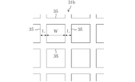
- FIG. 3 is a partially enlarged front view of the mesh shape of the dust collecting electrode portion of the first electrode plate.
- FIG. 4 is a perspective view showing a configuration of a pair of reinforcing frame members.
- FIG. 5 is a side cross-sectional view showing an operation when a water droplet flows down the surface of the dust collecting electrode portion.
- FIG. 6 is a plan view showing another configuration of the dust collecting electrode portion.
- FIG. 7 is a cross-sectional view showing a partially enlarged view of another configuration of the dust collecting electrode portion.
- FIG. 8 is a partially enlarged view showing another configuration of the dust collecting electrode portion.
- FIG. 9 is an enlarged cross-sectional view showing another configuration of the dust collecting electrode portion.
- Air passage 30 Charged dust collector (dust collector) 21a Water drop 31b Dust collection electrode (dust collection electrode) 32 Second electrode plate (dust collection electrode) 35 Wire 36a Horizontal reinforcing member (Reinforcing member) 36b Vertical reinforcement member (reinforcement member)
- FIG. 1 is a front view showing an overall configuration of an air purification apparatus provided with a dust collector according to an embodiment of the present invention.
- This air purification device (10) is intended for processing air (exhaust gas) discharged from kitchen spaces such as restaurants and hotels.
- air purification device (10) oil mist in the air (the oil is made into fine particles), other harmful substances, odorous substances and the like are removed.
- the air purification device (10) includes a vertically long casing (11).
- the casing (11) is formed in a hollow cylindrical shape or a rectangular cylindrical shape.
- a suction port (12) is opened in the upper part of the casing (11).
- the inlet (12) is connected to the kitchen space via a duct (not shown).
- the blower outlet (13) is opening, for example in the side surface of the lower part of a casing (11).
- the air outlet (13) faces the outdoor space.
- the blower outlet (13) is provided with a blower fan (14) for blowing air.
- the casing (11) is formed with an air passage (15) through which air flows from the inlet (12) to the outlet (13). That is, in the casing (11), the air passage (15) is formed so that air flows downward. Moreover, the storage tank (16) is formed in the bottom part of the casing (11). In the storage tank (16), spray water from a spray nozzle (21) to be described later is collected and stored.
- the discharge spray part (20), the charged dust collection part (30) as a dust collector, and air A demister section (40) for physically capturing the water droplet (21a) contained therein is provided.
- the discharge spray section (20) is provided with a spray nozzle (21) and a discharge electrode (22).
- the spray nozzle (21) sprays water toward the air, and the spray port faces downward.
- the spray nozzle (21) is configured to eject spray water in a hollow conical shape. That is, in the vicinity of the spray nozzle (21), the spray water exists only in the hollow conical region and does not substantially exist in the inside thereof.
- the outflow end of the water circulation channel (51) is connected to the upper end of the spray nozzle (21).
- the inflow end of the water circulation channel (51) is connected to the storage tank (16). That is, the water circulation channel (51) constitutes a channel for sending water accumulated in the storage tank (16) to the spray nozzle (21).
- the water circulation channel (51) is provided with a water circulation pump (52) and a water filter (53) in that order from the outflow side to the inflow side.
- the water circulation pump (52) constitutes a water conveyance means for pumping water accumulated in the storage tank (16) to the spray nozzle (21).
- the water filter (53) is means for physically capturing fine dust (solid particles) contained in the water flowing through the water circulation channel (51), and constitutes water purification means for purifying the water.
- the water circulation channel (51) and the water circulation pump (52) constitute a water circulation mechanism (50) for sending water accumulated in the storage tank (16) to the spray nozzle (21).
- the discharge electrode (22) is formed in a needle shape or a rod shape, and is held by the casing (11) or the like in a vertical posture.
- the tip of the discharge electrode (22) faces the spray port of the spray nozzle (21).
- Each discharge electrode (22) is located inside a hollow conical region where spray water of the spray nozzle (21) is present.
- a power source (23) is connected to the spray nozzle (21) and the discharge electrode (22) via a predetermined energization path.
- the power source (23) is preferably a high-voltage DC power source, but may be an AC power source or a pulse power source. Further, the power source (23) is preferably so-called constant current controlled so that the current value of the discharge from the discharge electrode (22) is constant.
- the spray nozzle (21) is on the negative electrode side
- the discharge electrode (22) is on the positive electrode side.
- a potential difference is applied from the power source (23) to the spray nozzle (21) and the discharge electrode (22).
- streamer discharge occurs from the discharge electrode (22) toward the spray water.
- FIG. 2 is an enlarged perspective view showing the configuration of the charged dust collecting portion.
- the charged dust collection part (30) is provided with the 1st electrode plate (31), the 2nd electrode plate (32), and the ionization electrode (33).
- the first electrode plate (31) is formed in a vertically long plate shape. In the air passage (15), the plurality of first electrode plates (31) are arranged in parallel at a predetermined interval while being held so as to stand in the vertical direction. In the first electrode plate (31), an approximately half portion near the upper side (upstream side) constitutes the charged electrode portion (31a), and an approximately half portion near the lower side (downstream side) is the dust collecting electrode portion. (31b) is configured. That is, the charging electrode part (31a) and the dust collecting electrode part (31b) are integrally formed on the first electrode plate (31).
- the ionization electrode (33) is provided at an intermediate position between adjacent charging electrode portions (31a).
- the ionization electrode (33) is obtained by forming the tip of the second electrode plate (32) in a sawtooth shape.
- the ionization electrode (33) constitutes a sharp protrusion protruding upward in a posture parallel to the first electrode plate (31).
- the charging electrode part (31a) and the ionization electrode (33) constitute a charging part for charging dust (mainly oil mist) in the air.
- the ionization electrode (33) may be formed separately from the second electrode plate (32), for example, or may be constituted by a rod-like or linear ionization line.
- the second electrode plate (32) is provided at an intermediate position between adjacent dust collecting electrode portions (31b).
- the second electrode plate (32) is formed in a plate shape parallel to the first electrode plate (31) and extending horizontally.
- the second electrode plate (32) is arranged so as to face each adjacent dust collecting electrode portion (31b).
- the second electrode plate (32) and the dust collecting electrode portion (31b) constitute a dust collecting portion for electrically attracting and capturing the dust charged by the charging portion.
- a power source (34) is connected to the first electrode plate (31) and the second electrode plate (32) via a predetermined energization path.
- the first electrode plate (31) is on the positive electrode side and the second electrode plate (32) is on the negative electrode side, oil mist or the like charged to a negative charge is collected on the positive electrode side. It adheres to the surface of the electrode part (31b).
- FIG. 3 is a partially enlarged front view showing the mesh shape of the dust collecting electrode portion of the first electrode plate.
- the dust collection electrode part (31b) of the first electrode plate (31) is formed in a mesh shape having a plurality of holes.
- the wire diameter L of the wire rod (35) constituting the mesh portion is set to 0.1 mm or more and 0.5 mm or less.
- the mesh opening W is set so as to satisfy the expression (1).
- FIG. 4 is a perspective view showing a configuration of a pair of reinforcing frame members.
- the dust collecting electrode portion (31b) of the first electrode plate (31) is formed of a mesh-like plate-like body, a pair of reinforcing frame members ( It is preferable that the structure is sandwiched between 36 and 36).
- the reinforcing frame member (36) sandwiches the surface of the dust collecting electrode part (31b) and extends vertically from the center position of the dust collecting electrode part (31b).
- a horizontal reinforcing member (36a) extending horizontally along the surface at the displaced position, a vertical reinforcing member (36b) extending vertically along both left and right edges of the dust collecting electrode portion (31b), and dust collecting
- An outer frame member (36c) extending in the horizontal direction along both vertical edges of the electrode portion (31b).
- the reinforcing frame member (36) is disposed on both surfaces of the dust collecting electrode part (31b), and sandwiches the dust collecting electrode part (31b).
- the horizontal reinforcing member (36a) is disposed at a position where they do not overlap each other when viewed from the surface direction of the dust collecting electrode portion (31b).
- the water droplet (21a) can flow smoothly along the surface of the dust collection electrode part (31b) while reinforcing the mesh-like dust collection electrode part (31b).
- the dust collecting electrode portion (31b) of the first electrode plate (31) has been described as being formed in a mesh shape.
- the present invention is not limited to this configuration, and water droplets ( Any structure that reduces the interfacial tension between 21a) and the dust collecting electrode part (31b) may be used.
- the dust collecting electrode part (31b) may be composed of a porous material such as ceramics (see FIG. 8), and the interfacial tension may be reduced by water droplets (21a) entering the pores on the surface. .
- the surface is made of a hydrophilic material, a mesh-like dust collecting electrode part (31b), a dust collecting electrode part (31b) made of a porous material, and a dust collecting electrode subjected to hairline processing described later
- the surface tension such as the part (31b) is coated with a hydrophilic material to form a film (31c) (see FIG. 9), and the water droplet (21a) adhering to the surface is soaked to reduce the interfacial tension. May be.
- the surface of the dust collecting electrode portion (31b) of the first electrode plate (31) is subjected to hairline processing, thereby extending in the vertical direction and in the horizontal direction.
- An uneven portion may be formed by providing a plurality of guide grooves (37) at intervals, and the interfacial tension may be lowered by the water droplet (21a) entering the uneven portion.
- the air purification device (10) When the air purification device (10) is in operation, the blower fan (14) and the water circulation pump (52) are in operation. Further, a voltage is applied from the power source (23) to the spray nozzle (21) and the discharge electrode (22), and a voltage is applied from the power source (34) to the first electrode plate (31) and the second electrode plate (32). .
- Such streamer discharge generates active species (fast electrons, ions, ozone, radicals, and other excited molecules (excited oxygen molecules, excited nitrogen molecules, excited water molecules, etc.)) in the discharge spray section (20).
- active species fast electrons, ions, ozone, radicals, and other excited molecules (excited oxygen molecules, excited nitrogen molecules, excited water molecules, etc.)
- generation of OH radicals is promoted in the presence of water.
- the generated active species are scattered so as to adhere to the sprayed water, so that the diffusion effect of the active species is increased.
- harmful substances and odorous substances contained in the air are removed by oxidative decomposition by reacting with the active species.
- hydrophilic substances are absorbed and captured by the spray water.
- hydrophobic substances among odorous substances are easily oxidized and become hydrophilic by active species. Accordingly, the odorous substance that has become hydrophilic is also absorbed and captured by the spray water.
- the oxidative decomposition action of harmful substances caused by streamer discharge and the absorption / dissolution action of harmful substances using spray water from the spray nozzle (21) ie, scrubber action.
- Such removal of harmful substances and the like is also performed on the downstream side of the discharge spray section (20) in the air passage (15).
- air first passes between the charged electrode part (31a) and the ionization electrode (33).
- corona discharge is performed between the ionization electrode (33) and the charged electrode portion (31a). Due to this corona discharge, oil mist and the like in the air are negatively charged.
- the air passes between the second electrode plate (32) and the dust collecting electrode part (31b).
- oil mist or the like charged to a negative charge adheres to the surface of the dust collecting electrode portion (31b) on the positive electrode side.
- oil mist or the like is attracted and captured on the dust collection surface facing the horizontal side. Thereby, oil mist etc. in the air are removed.
- the sprayed water sprayed from the spray nozzle (21) drops downward due to its own weight, and further flows downward together with air to surface the first electrode plate (31) and the second electrode plate (32). Is actively sent to. As a result, oil or the like adhering to the dust collecting electrode part (31b) is washed away by the spray water. Further, when oil adheres to the second electrode plate (32) or the ionization electrode (33), this oil is also washed away by the spray water. Furthermore, since the first electrode plate (31) and the second electrode plate (32) are in a vertical posture, the spray water flows down along the surface of each electrode plate (31, 32). Thereby, the cleaning effect of each electrode plate (31, 32) increases.
- each electrode plate (31, 32) since the above-mentioned active species are contained in the spray water, the oil etc. adhering to the surface of each electrode plate (31, 32) is gradually oxidized and decomposed by this active species. As a result, oil or the like changes to a hydrophilic substance, so that it is easily dissolved in spray water, and the cleaning effect of each electrode plate (31, 32) is further improved.
- the charged dust collection part (30) an effective dust collection area is ensured by appropriately cleaning the dust collection surface of the dust collection electrode part (31b). Thereby, in the charged dust collection part (30), the desired dust collection performance is maintained over a long period of time.
- the water captured by the demister section (40) is dropped downward and collected in the storage tank (16).
- the water stored in the storage tank (16) is sucked into the water circulation channel (51) by the water circulation pump (52), passes through the water filter (53), and is sprayed again into the air from the spray nozzle (21).
- the air purification apparatus (10) of this embodiment is used for the exhaust gas treatment of a kitchen space, this air purification apparatus (10) can also be utilized as an air cleaner for general households.
- the present invention has a highly practical effect that suppresses the coarsening of water droplets on the surface of the dust collecting electrode and suppresses the decrease in dust collecting performance due to the adhesion of dust and the like. Therefore, it is extremely useful and has high industrial applicability.
Abstract
Description
前記集塵電極(31b)は、その表面に付着した水滴(21a)と該集塵電極(31b)との間の界面張力を低下させるように構成されていることを特徴とするものである。
前記集塵電極(31b)は、多孔質材料で構成されていることを特徴とするものである。
前記集塵電極(31b)は、複数の孔を有する網目状の板状体で構成され、
前記集塵電極(31b)を構成する線材(35)の線径が、0.1mm以上0.5mm以下に設定されていることを特徴とするものである。
前記集塵電極(31b)は、複数の孔を有する網目状の板状体で構成され、
前記集塵電極(31b)を構成する線材(35)の線径L、網目の開き目Wが、
1≦W/L≦4
という条件を満たすように設定されていることを特徴とするものである。
前記集塵電極(31b)は、鉛直方向に立設するように配設され、
前記集塵電極(31b)の表面に沿って鉛直方向に延び、該集塵電極(31b)を挟持する一対の補強部材(36b)を備えたことを特徴とするものである。
前記集塵電極(31b)は、鉛直方向に立設するように配設され、
前記集塵電極(31b)の表面に沿って水平方向に延び、該集塵電極(31b)を挟持する一対の補強部材(36a)を備え、
前記一対の補強部材(36a)は、前記集塵電極(31b)の面方向から見て互いにオーバーラップしない位置に配設されていることを特徴とするものである。
前記集塵電極(31b)の表面には、凹凸部が形成されていることを特徴とするものである。
前記集塵電極(31b)の少なくとも表面は、親水性材料で構成されていることを特徴とするものである。
30 荷電集塵部(集塵装置)
21a 水滴
31b 集塵電極部(集塵電極)
32 第2電極板(集塵電極)
35 線材
36a 水平補強部材(補強部材)
36b 鉛直補強部材(補強部材)
このような構成とすれば、第1電極板(31)の集塵電極部(31b)の表面に付着した水滴(21a)と集塵電極部(31b)との間の界面張力を低下させる上で有利となる。すなわち、開き目Wが大きすぎると集塵電極部(31b)の表面に水膜が形成されずに孔があいたままの状態となって集塵効率が低下する一方、開き目Wが小さすぎると水滴(21a)と集塵電極部(31b)との間の界面張力を低下させる効果が薄れてしまうため、本発明のように、線材(35)の線径Lと開き目Wとに基づいて網目形状を条件設定すれば、上記界面張力を効率的に低下させることができる。
次に、本実施形態に係る空気浄化装置(10)の運転動作について説明する。空気浄化装置(10)の運転時には、送風ファン(14)及び水循環ポンプ(52)が運転状態となる。また、電源(23)から噴霧ノズル(21)及び放電電極(22)へ電圧が印加され、電源(34)から第1電極板(31)及び第2電極板(32)へ電圧が印加される。
Claims (10)
- 水滴(21a)が供給される空気通路(15)に配設され、油分を含む空気中の塵埃を捕集する集塵装置であって、
空気中で帯電させた塵埃を電気的に誘引する集塵電極(31b)を備え、
前記集塵電極(31b)は、その表面に付着した水滴(21a)と該集塵電極(31b)との間の界面張力を低下させるように構成されていることを特徴とする集塵装置。 - 請求項1において、
前記集塵電極(31b)は、多孔質材料で構成されていることを特徴とする集塵装置。 - 請求項1において、
前記集塵電極(31b)は、複数の孔を有する網目状の板状体で構成され、
前記集塵電極(31b)を構成する線材(35)の線径が、0.1mm以上0.5mm以下に設定されていることを特徴とする集塵装置。 - 請求項1において、
前記集塵電極(31b)は、複数の孔を有する網目状の板状体で構成され、
前記集塵電極(31b)を構成する線材(35)の線径L、網目の開き目Wが、
1≦W/L≦4
という条件を満たすように設定されていることを特徴とする集塵装置。 - 請求項3において、
前記集塵電極(31b)は、鉛直方向に立設するように配設され、
前記集塵電極(31b)の表面に沿って鉛直方向に延び、該集塵電極(31b)を挟持する一対の補強部材(36b)を備えたことを特徴とする集塵装置。 - 請求項3において、
前記集塵電極(31b)は、鉛直方向に立設するように配設され、
前記集塵電極(31b)の表面に沿って水平方向に延び、該集塵電極(31b)を挟持する一対の補強部材(36a)を備え、
前記一対の補強部材(36a)は、前記集塵電極(31b)の面方向から見て互いにオーバーラップしない位置に配設されていることを特徴とする集塵装置。 - 請求項1において、
前記集塵電極(31b)の表面には、凹凸部が形成されていることを特徴とする集塵装置。 - 請求項1において、
前記集塵電極(31b)の少なくとも表面は、親水性材料で構成されていることを特徴とする集塵装置。 - 請求項4において、
前記集塵電極(31b)は、鉛直方向に立設するように配設され、
前記集塵電極(31b)の表面に沿って鉛直方向に延び、該集塵電極(31b)を挟持する一対の補強部材(36b)を備えたことを特徴とする集塵装置。 - 請求項4において、
前記集塵電極(31b)は、鉛直方向に立設するように配設され、
前記集塵電極(31b)の表面に沿って水平方向に延び、該集塵電極(31b)を挟持する一対の補強部材(36a)を備え、
前記一対の補強部材(36a)は、前記集塵電極(31b)の面方向から見て互いにオーバーラップしない位置に配設されていることを特徴とする集塵装置。
Priority Applications (3)
| Application Number | Priority Date | Filing Date | Title |
|---|---|---|---|
| EP09712517.3A EP2246117A4 (en) | 2008-02-20 | 2009-02-20 | DUST COLLECTOR |
| JP2009554227A JPWO2009104411A1 (ja) | 2008-02-20 | 2009-02-20 | 集塵装置 |
| US12/867,419 US8465575B2 (en) | 2008-02-20 | 2009-02-20 | Dust collector |
Applications Claiming Priority (2)
| Application Number | Priority Date | Filing Date | Title |
|---|---|---|---|
| JP2008-039283 | 2008-02-20 | ||
| JP2008039283 | 2008-02-20 |
Publications (1)
| Publication Number | Publication Date |
|---|---|
| WO2009104411A1 true WO2009104411A1 (ja) | 2009-08-27 |
Family
ID=40985297
Family Applications (1)
| Application Number | Title | Priority Date | Filing Date |
|---|---|---|---|
| PCT/JP2009/000734 WO2009104411A1 (ja) | 2008-02-20 | 2009-02-20 | 集塵装置 |
Country Status (4)
| Country | Link |
|---|---|
| US (1) | US8465575B2 (ja) |
| EP (1) | EP2246117A4 (ja) |
| JP (1) | JPWO2009104411A1 (ja) |
| WO (1) | WO2009104411A1 (ja) |
Cited By (4)
| Publication number | Priority date | Publication date | Assignee | Title |
|---|---|---|---|---|
| JP2012090671A (ja) * | 2010-10-25 | 2012-05-17 | Daikin Industries Ltd | 空気浄化装置 |
| EP2456544B1 (en) * | 2009-07-22 | 2013-12-18 | Technische Universiteit Delft | Method for the removal of a gaseous fluid and arrangement therefore |
| AU2009317678B2 (en) * | 2008-11-20 | 2014-03-06 | Westfaelische Hochschule Gelsenkirchen, Bocholt, Recklinghausen | Wet-cleaning electrostatic filter for cleaning exhaust gas and a suitable method for the same |
| KR20180105844A (ko) * | 2017-03-16 | 2018-10-01 | 경남과학기술대학교 산학협력단 | 공기전파감염원 살균용 간이벽체 |
Families Citing this family (18)
| Publication number | Priority date | Publication date | Assignee | Title |
|---|---|---|---|---|
| JP2012058015A (ja) * | 2010-09-07 | 2012-03-22 | Ngk Insulators Ltd | 粒子状物質検出装置 |
| WO2014084442A1 (ko) * | 2012-11-30 | 2014-06-05 | 주식회사 지홈 | 전기변위장을 이용한 전기집진 장치 |
| KR200478999Y1 (ko) | 2013-11-27 | 2015-12-09 | 주식회사 지홈 | 집진 장치용 집진판 |
| JP2015536241A (ja) * | 2012-11-30 | 2015-12-21 | ジホム カンパニー リミテッドZIHOM Co., Ltd | 電気集塵システムに備えられる電気集塵装置及びその電気集塵装置を利用した集塵方法 |
| FR3006602B1 (fr) * | 2013-06-10 | 2016-01-29 | Vivirad | Dispositif de traitement d'au moins un flux d'effluents gazeux |
| KR102199381B1 (ko) * | 2013-12-05 | 2021-01-06 | 엘지전자 주식회사 | 공기조화기용 공기청정기구 |
| EP3204164B1 (en) * | 2014-10-08 | 2021-07-07 | Sic S.r.l. | Electrostatic filter for purifying a gas flow |
| CN106999951B (zh) | 2014-10-16 | 2022-01-28 | 俄亥俄州立大学 | 湿式静电除尘器以及处理废气的方法 |
| DE102014018903A1 (de) * | 2014-12-17 | 2016-06-23 | Eisenmann Se | Vorrichtung und Verfahren zum Abscheiden von Partikeln aus einem Abluftstrom einer Beschichtungskabine |
| IL258235B (en) * | 2015-09-28 | 2022-07-01 | Massachusetts Inst Technology | Systems and methods for compound collection |
| KR102527658B1 (ko) * | 2016-03-02 | 2023-05-03 | 삼성전자주식회사 | 공기청정기 |
| KR102540335B1 (ko) * | 2016-12-09 | 2023-06-05 | 삼성전자주식회사 | 전기집진장치 및 이를 포함하는 가습공기청정기 |
| CH713394A1 (de) | 2017-01-30 | 2018-07-31 | Clean Air Entpr Ag | Elektrofilter. |
| CN106875575A (zh) * | 2017-02-23 | 2017-06-20 | 苏州云白环境设备股份有限公司 | 一种商用油烟净化系统的计费方法 |
| CN107115969B (zh) * | 2017-03-30 | 2018-08-24 | 区永辉 | 一种空气净化器及方法 |
| KR102070053B1 (ko) * | 2018-05-02 | 2020-01-28 | 엘지전자 주식회사 | 전기집진장치 및 이를 포함하는 공기조화기 |
| JP6660065B2 (ja) * | 2018-06-06 | 2020-03-04 | 住友金属鉱山エンジニアリング株式会社 | 電気集塵装置用の電源制御装置及び方法 |
| AU2019372085A1 (en) * | 2018-11-02 | 2021-05-27 | Breakthrough Technologies, LLC | Condensing vapor |
Citations (8)
| Publication number | Priority date | Publication date | Assignee | Title |
|---|---|---|---|---|
| JPS5026069Y1 (ja) * | 1973-05-01 | 1975-08-04 | ||
| JPS5157074A (ja) * | 1974-11-14 | 1976-05-19 | Miura Eng Int | Shujinsochi |
| JPS6118455A (ja) * | 1984-07-06 | 1986-01-27 | Masahiko Tsunoda | 湿式電気集塵機の集塵極板の改良 |
| JPH10156214A (ja) * | 1996-11-28 | 1998-06-16 | Matsushita Seiko Co Ltd | 水蒸気の回収装置 |
| JP2000189836A (ja) * | 1998-12-28 | 2000-07-11 | Hitachi Plant Eng & Constr Co Ltd | 湿式電気集塵装置 |
| JP2000354787A (ja) * | 1999-04-15 | 2000-12-26 | Watanabe Seisakusho:Kk | 湿式電気集塵装置 |
| JP3126819B2 (ja) | 1992-07-31 | 2001-01-22 | 健一 中川 | 湿式電気集塵装置 |
| JP2001121030A (ja) * | 1999-08-13 | 2001-05-08 | Mitsubishi Heavy Ind Ltd | 除塵装置および除塵方法 |
Family Cites Families (19)
| Publication number | Priority date | Publication date | Assignee | Title |
|---|---|---|---|---|
| US3570218A (en) * | 1968-12-11 | 1971-03-16 | Universal Oil Prod Co | Electrode configuration in an electrical precipitator |
| JPS5259374A (en) * | 1975-11-10 | 1977-05-16 | Hitachi Plant Eng & Constr Co Ltd | Dust-collector electrode for wet-type electric dust collector |
| JPS5634565U (ja) * | 1979-08-25 | 1981-04-04 | ||
| EP0039461A1 (de) * | 1980-05-05 | 1981-11-11 | Kunststofftechnik KG | Verfahren und Vorrichtung zur Abluftreinigung |
| US4597780A (en) * | 1981-06-04 | 1986-07-01 | Santek, Inc. | Electro-inertial precipitator unit |
| DE3503759A1 (de) * | 1985-02-05 | 1986-08-07 | Bayer Ag, 5090 Leverkusen | Verfahren zur elektrischen abscheidung von partikeln aus einem gasstrom |
| JP2688004B2 (ja) * | 1990-05-18 | 1997-12-08 | 住友重機械工業株式会社 | 湿式電気集塵装置におけるダスト付着防止方法 |
| US5160510A (en) * | 1990-06-09 | 1992-11-03 | Metallgesellschaft Aktiengesellschaft | Process and apparatus for purifying dust- and pollutant-containing exhaust gases |
| JPH0474547A (ja) * | 1990-07-16 | 1992-03-09 | Aeria:Kk | 空気清浄機 |
| JP3187205B2 (ja) * | 1993-05-07 | 2001-07-11 | 健一 中川 | 排ガスの処理方法 |
| DE69514059T2 (de) * | 1994-09-21 | 2000-05-25 | Allrad No 28 Pty Ltd | Eine elektrostatische Niederschlagsvorrichtung |
| US5626652A (en) * | 1996-06-05 | 1997-05-06 | Environmental Elements Corporation | Laminar flow electrostatic precipitator having a moving electrode |
| US6471753B1 (en) * | 1999-10-26 | 2002-10-29 | Ace Lab., Inc. | Device for collecting dust using highly charged hyperfine liquid droplets |
| US6843835B2 (en) * | 2001-03-27 | 2005-01-18 | The Procter & Gamble Company | Air cleaning apparatus and method for cleaning air |
| US6508861B1 (en) * | 2001-10-26 | 2003-01-21 | Croll Reynolds Clean Air Technologies, Inc. | Integrated single-pass dual-field electrostatic precipitator and method |
| US6783575B2 (en) * | 2002-05-09 | 2004-08-31 | Ohio University | Membrane laminar wet electrostatic precipitator |
| US7273516B2 (en) * | 2003-03-26 | 2007-09-25 | Mentus Holding Ag | Plate heat exchanger |
| WO2005107925A1 (fr) * | 2004-05-08 | 2005-11-17 | Qingbao Huang | Dispositif d'elimination de poussiere de fumee du mazout |
| SE530738C2 (sv) * | 2006-06-07 | 2008-08-26 | Alstom Technology Ltd | Våtelfilter samt sätt att rengöra en utfällningselektrod |
-
2009
- 2009-02-20 JP JP2009554227A patent/JPWO2009104411A1/ja active Pending
- 2009-02-20 US US12/867,419 patent/US8465575B2/en not_active Expired - Fee Related
- 2009-02-20 EP EP09712517.3A patent/EP2246117A4/en not_active Withdrawn
- 2009-02-20 WO PCT/JP2009/000734 patent/WO2009104411A1/ja active Application Filing
Patent Citations (8)
| Publication number | Priority date | Publication date | Assignee | Title |
|---|---|---|---|---|
| JPS5026069Y1 (ja) * | 1973-05-01 | 1975-08-04 | ||
| JPS5157074A (ja) * | 1974-11-14 | 1976-05-19 | Miura Eng Int | Shujinsochi |
| JPS6118455A (ja) * | 1984-07-06 | 1986-01-27 | Masahiko Tsunoda | 湿式電気集塵機の集塵極板の改良 |
| JP3126819B2 (ja) | 1992-07-31 | 2001-01-22 | 健一 中川 | 湿式電気集塵装置 |
| JPH10156214A (ja) * | 1996-11-28 | 1998-06-16 | Matsushita Seiko Co Ltd | 水蒸気の回収装置 |
| JP2000189836A (ja) * | 1998-12-28 | 2000-07-11 | Hitachi Plant Eng & Constr Co Ltd | 湿式電気集塵装置 |
| JP2000354787A (ja) * | 1999-04-15 | 2000-12-26 | Watanabe Seisakusho:Kk | 湿式電気集塵装置 |
| JP2001121030A (ja) * | 1999-08-13 | 2001-05-08 | Mitsubishi Heavy Ind Ltd | 除塵装置および除塵方法 |
Non-Patent Citations (1)
| Title |
|---|
| See also references of EP2246117A4 * |
Cited By (5)
| Publication number | Priority date | Publication date | Assignee | Title |
|---|---|---|---|---|
| AU2009317678B2 (en) * | 2008-11-20 | 2014-03-06 | Westfaelische Hochschule Gelsenkirchen, Bocholt, Recklinghausen | Wet-cleaning electrostatic filter for cleaning exhaust gas and a suitable method for the same |
| EP2456544B1 (en) * | 2009-07-22 | 2013-12-18 | Technische Universiteit Delft | Method for the removal of a gaseous fluid and arrangement therefore |
| JP2012090671A (ja) * | 2010-10-25 | 2012-05-17 | Daikin Industries Ltd | 空気浄化装置 |
| KR20180105844A (ko) * | 2017-03-16 | 2018-10-01 | 경남과학기술대학교 산학협력단 | 공기전파감염원 살균용 간이벽체 |
| KR101961214B1 (ko) * | 2017-03-16 | 2019-03-22 | 경남과학기술대학교 산학협력단 | 공기전파감염원 살균용 간이벽체 |
Also Published As
| Publication number | Publication date |
|---|---|
| EP2246117A4 (en) | 2014-01-29 |
| US20100313761A1 (en) | 2010-12-16 |
| JPWO2009104411A1 (ja) | 2011-06-23 |
| EP2246117A1 (en) | 2010-11-03 |
| US8465575B2 (en) | 2013-06-18 |
Similar Documents
| Publication | Publication Date | Title |
|---|---|---|
| WO2009104411A1 (ja) | 集塵装置 | |
| US8419841B2 (en) | Air processing device | |
| JP4111229B2 (ja) | 放電装置及び空気浄化装置 | |
| JP5546630B2 (ja) | 微生物・ウイルスの捕捉・不活化装置 | |
| JP5855122B2 (ja) | 微生物・ウイルスの捕捉・不活化装置及びその方法 | |
| JP5040612B2 (ja) | 空気浄化装置 | |
| KR101959628B1 (ko) | 공기 청정을 위한 샤워필터 | |
| KR101959980B1 (ko) | 필터 없는 미세먼지 제거기 | |
| JP4894739B2 (ja) | 湿式電気集塵機 | |
| CN103949343A (zh) | 空气净化装置 | |
| JP2011131132A (ja) | 溶接ヒューム集塵装置 | |
| JP6460890B2 (ja) | 荷電装置及び電気集塵機 | |
| JP2008006371A (ja) | 集塵装置 | |
| JP5098915B2 (ja) | 集塵装置 | |
| JP2012090671A (ja) | 空気浄化装置 | |
| JP4760567B2 (ja) | 放電装置、空気浄化装置、及び液処理装置 | |
| CN103586129A (zh) | 静电空气净化装置及方法 | |
| JP3656517B2 (ja) | 空気浄化装置 | |
| JP2009125123A (ja) | 空気浄化装置 | |
| JP2009125122A (ja) | 空気浄化装置 | |
| KR20190036043A (ko) | 분사형 습식노즐이 구비된 공기청정기 | |
| JP4561256B2 (ja) | 空気清浄装置付空気調和機 | |
| RU2482395C1 (ru) | Способ очистки воздуха | |
| JP2015182000A (ja) | 空気浄化装置 | |
| JP2012091080A (ja) | 集塵装置 |
Legal Events
| Date | Code | Title | Description |
|---|---|---|---|
| 121 | Ep: the epo has been informed by wipo that ep was designated in this application |
Ref document number: 09712517 Country of ref document: EP Kind code of ref document: A1 |
|
| WWE | Wipo information: entry into national phase |
Ref document number: 2009554227 Country of ref document: JP |
|
| REEP | Request for entry into the european phase |
Ref document number: 2009712517 Country of ref document: EP |
|
| WWE | Wipo information: entry into national phase |
Ref document number: 2009712517 Country of ref document: EP |
|
| WWE | Wipo information: entry into national phase |
Ref document number: 12867419 Country of ref document: US |
|
| NENP | Non-entry into the national phase |
Ref country code: DE |