WO2009093444A1 - Membrane de haut-parleur, haut-parleur utilisant ladite membrane et procédé de fabrication d'une membrane de haut-parleur - Google Patents
Membrane de haut-parleur, haut-parleur utilisant ladite membrane et procédé de fabrication d'une membrane de haut-parleur Download PDFInfo
- Publication number
- WO2009093444A1 WO2009093444A1 PCT/JP2009/000193 JP2009000193W WO2009093444A1 WO 2009093444 A1 WO2009093444 A1 WO 2009093444A1 JP 2009000193 W JP2009000193 W JP 2009000193W WO 2009093444 A1 WO2009093444 A1 WO 2009093444A1
- Authority
- WO
- WIPO (PCT)
- Prior art keywords
- woven fabric
- fabric layer
- speaker diaphragm
- speaker
- mold
- Prior art date
Links
Images


Classifications
-
- H—ELECTRICITY
- H04—ELECTRIC COMMUNICATION TECHNIQUE
- H04R—LOUDSPEAKERS, MICROPHONES, GRAMOPHONE PICK-UPS OR LIKE ACOUSTIC ELECTROMECHANICAL TRANSDUCERS; DEAF-AID SETS; PUBLIC ADDRESS SYSTEMS
- H04R7/00—Diaphragms for electromechanical transducers; Cones
- H04R7/02—Diaphragms for electromechanical transducers; Cones characterised by the construction
- H04R7/12—Non-planar diaphragms or cones
- H04R7/122—Non-planar diaphragms or cones comprising a plurality of sections or layers
- H04R7/125—Non-planar diaphragms or cones comprising a plurality of sections or layers comprising a plurality of superposed layers in contact
-
- H—ELECTRICITY
- H04—ELECTRIC COMMUNICATION TECHNIQUE
- H04R—LOUDSPEAKERS, MICROPHONES, GRAMOPHONE PICK-UPS OR LIKE ACOUSTIC ELECTROMECHANICAL TRANSDUCERS; DEAF-AID SETS; PUBLIC ADDRESS SYSTEMS
- H04R31/00—Apparatus or processes specially adapted for the manufacture of transducers or diaphragms therefor
- H04R31/003—Apparatus or processes specially adapted for the manufacture of transducers or diaphragms therefor for diaphragms or their outer suspension
-
- H—ELECTRICITY
- H04—ELECTRIC COMMUNICATION TECHNIQUE
- H04R—LOUDSPEAKERS, MICROPHONES, GRAMOPHONE PICK-UPS OR LIKE ACOUSTIC ELECTROMECHANICAL TRANSDUCERS; DEAF-AID SETS; PUBLIC ADDRESS SYSTEMS
- H04R2307/00—Details of diaphragms or cones for electromechanical transducers, their suspension or their manufacture covered by H04R7/00 or H04R31/003, not provided for in any of its subgroups
- H04R2307/021—Diaphragms comprising cellulose-like materials, e.g. wood, paper, linen
-
- H—ELECTRICITY
- H04—ELECTRIC COMMUNICATION TECHNIQUE
- H04R—LOUDSPEAKERS, MICROPHONES, GRAMOPHONE PICK-UPS OR LIKE ACOUSTIC ELECTROMECHANICAL TRANSDUCERS; DEAF-AID SETS; PUBLIC ADDRESS SYSTEMS
- H04R2307/00—Details of diaphragms or cones for electromechanical transducers, their suspension or their manufacture covered by H04R7/00 or H04R31/003, not provided for in any of its subgroups
- H04R2307/029—Diaphragms comprising fibres
Definitions
- the present invention relates to a speaker diaphragm and a speaker using the same.
- the speaker diaphragm used in the speaker has a large Young's modulus and an appropriate internal loss.
- FIG. 17 is a perspective view of a conventional speaker diaphragm.
- the speaker diaphragm 204 is composed of an inorganic fiber woven fabric 201 and a laminate 203 in which a natural fiber nonwoven fabric 202 is superimposed on the lower surface thereof.
- the inorganic fiber woven fabric 201 having a small Young loss but a large Young's modulus and the natural fiber non-woven fabric 202 having a small Young's modulus but a large Young's loss are bonded to each other, whereby both the Young's modulus and the internal loss are excellent. It was intended to realize the characteristics.
- This technical content is disclosed in Patent Document 1.
- the present invention improves the sound quality of the speaker by increasing the Young's modulus and internal loss of the speaker diaphragm.
- the speaker diaphragm according to the present invention includes a woven fabric layer in which the impregnated thermosetting resin is in a thermosetting state, and a paper layer integrated on the back side of the woven fabric layer.
- the fluffs of the paper layer filled in the fabric were entangled with the woven yarn of the woven fabric layer from the surface side of the woven fabric layer and integrated with the thermosetting resin.
- the speaker diaphragm according to the present invention includes a woven fabric layer impregnated with a thermosetting resin, and a nonwoven fabric layer that is pressure-bonded and integrated with at least heat on the back side of the woven fabric layer.
- a woven fabric layer impregnated with a thermosetting resin and a nonwoven fabric layer that is pressure-bonded and integrated with at least heat on the back side of the woven fabric layer.
- the present invention can increase the Young's modulus and internal loss of the speaker diaphragm and improve the sound quality of the speaker.
- FIG. 1A is a perspective view of a speaker diaphragm in accordance with the first exemplary embodiment of the present invention.
- FIG. 1B is an enlarged view of a main part when the speaker diaphragm according to Embodiment 1 of the present invention is viewed from the surface side.
- FIG. 2 is a schematic cross-sectional view taken along broken line 2-2 in FIG. 1B.
- FIG. 3 is a cross-sectional view of a speaker using the speaker diaphragm according to Embodiment 1 of the present invention.
- FIG. 4 is a diagram showing a molding machine constituted by a first mold and a second mold for forming the speaker diaphragm in the first embodiment of the present invention.
- FIG. 1A is a perspective view of a speaker diaphragm in accordance with the first exemplary embodiment of the present invention.
- FIG. 1B is an enlarged view of a main part when the speaker diaphragm according to Embodiment 1 of the present invention is
- FIG. 5 is a cross-sectional view showing a method for manufacturing the speaker diaphragm in accordance with the first exemplary embodiment of the present invention.
- FIG. 6 is a cross-sectional view of the raw material of the speaker diaphragm in the first exemplary embodiment of the present invention.
- FIG. 7 is a cross-sectional view showing a method for manufacturing the speaker diaphragm in accordance with the first exemplary embodiment of the present invention.
- FIG. 8 is a cross-sectional view showing a method for manufacturing the speaker diaphragm in the first embodiment of the present invention.
- FIG. 9A is a perspective view of the speaker diaphragm according to the second exemplary embodiment of the present invention.
- FIG. 9B is an enlarged view of a main part when the speaker diaphragm according to Embodiment 1 of the present invention is viewed from the front side.
- FIG. 10 is a schematic cross-sectional view taken along broken line 10-10 in FIG. 9B.
- FIG. 11 is a cross-sectional view of a speaker using the speaker diaphragm according to Embodiment 2 of the present invention.
- FIG. 12 is a diagram illustrating a molding machine configured with a first mold and a second mold for forming the speaker diaphragm in the second embodiment of the present invention.
- FIG. 13 is a cross-sectional view illustrating a method for manufacturing the speaker diaphragm in accordance with the second exemplary embodiment of the present invention.
- FIG. 14 is a cross-sectional view of the raw material of the speaker diaphragm in the second exemplary embodiment of the present invention.
- FIG. 15 is a cross-sectional view showing a method of manufacturing the speaker diaphragm in the second embodiment of the present invention.
- FIG. 16 is a cross-sectional view illustrating the method for manufacturing the speaker diaphragm in the second embodiment of the present invention.
- FIG. 17 is a perspective view of a conventional speaker diaphragm.
- FIG. 1A is a perspective view of a speaker diaphragm in accordance with the first exemplary embodiment of the present invention.
- the speaker diaphragm 5 has a two-layer structure of a woven fabric layer 6 and a paper layer 7.
- the woven fabric layer 6 is formed by weaving two types of woven yarns 9 of warp yarns 8a and weft yarns 8b in a lattice shape, and the lattice stripes are exposed on the surface of the diaphragm 5 for speakers.
- thermosetting resin exists in the inside and the outer periphery of the warp yarn 8a and the weft yarn 8b, and the warp yarn 8a and the weft yarn 8b itself are obtained by thermosetting the thermosetting resin.
- the woven fabric layer 6 formed by weaving them is in a cured state.
- the woven fabric layer 6 is configured to contain at least one of high-strength fibers such as aramid fibers, polyester fibers, acrylic fibers, cotton fibers, carbon fibers, glass fibers, silk fibers, and the like as a thermosetting resin.
- aramid fibers such as aramid fibers, polyester fibers, acrylic fibers, cotton fibers, carbon fibers, glass fibers, silk fibers, and the like as a thermosetting resin.
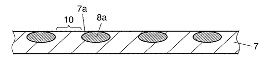
- the paper layer 7 is formed by mixing aramid fibers with cellulose fibers, and is integrated on the back side of the woven fabric layer 6 by thermocompression bonding. Thus, since the paper layer 7 is thermocompression integrated on the back side of the woven fabric layer 6, air does not pass from the front surface side to the back surface side of the speaker diaphragm 5. Further, the pulp constituting the paper layer 7 is filled in a stitch 10 that is a portion surrounded by adjacent warp yarns 8 a and weft yarns 8 b of the woven fabric layer 6.
- FIG. 1B is an enlarged view of a main part when the speaker diaphragm according to Embodiment 1 of the present invention is viewed from the surface side.
- the pulp fluff 7 a of the paper layer 7 is entangled with the warp yarn 8 a and the weft yarn 8 b from the surface side of the woven fabric layer 6, and is cured with a thermosetting resin together with the woven yarn 9.
- the stitch 10 refers to a substantially rectangular parallelepiped portion whose bottom surface is surrounded by the warp yarn 8 a and the weft yarn 8 b and whose height is equal to the thickness of the woven yarn 9.
- FIG. 2 is a schematic cross-sectional view taken along broken line 2-2 in FIG. 1B.
- the portion of the stitch 10 between the warp yarns 8 a is filled with pulp of the paper layer 7, and the fluff 7 a of the pulp of the paper layer 7 is warp yarn from the surface side of the woven fabric layer 6. It is thermocompression bonded in a state of being entangled with 8a.
- the state where the fluff 7a is entangled with the warp 8a has been described.
- the fluff 7a is entangled similarly to the warp 8a.
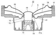
- FIG. 3 is a cross-sectional view of a speaker using the speaker diaphragm according to the first embodiment of the present invention.
- a speaker 12 includes a magnetic circuit 14 having a cylindrical magnetic gap 13 and a cylindrical voice coil in which a portion having a coil 15 is movably disposed in the magnetic gap 13 of the magnetic circuit 14. And a body 16.
- the inner peripheral portion of the shallow plate-like speaker diaphragm 5 is connected to the outer portion of the magnetic gap 13 of the voice coil body 16, and the outer peripheral portion of the speaker diaphragm 5 is connected to the deep dish-like frame 17.
- the cross-sectional shape held in the upper surface opening portion is connected to the inner peripheral portion of the ring-shaped first edge 18.
- a hemispherical dust cap 19 is provided near the inner peripheral portion of the speaker diaphragm 5 so as to cover the upper surface side of the voice coil body 16. It has a function to prevent intrusion of moisture and the like.
- the lead wire 20 from the coil 15 of the voice coil body 16 is not in contact with the speaker diaphragm 5 between the connection portion of the speaker diaphragm 5 of the voice coil body 16 and the portion disposed in the magnetic gap 13. It is pulled out to the frame 17 in a state.
- the inner peripheral end of the second edge 21 having a ring-shaped cross section formed by an elastic body is formed in a portion of the voice coil body 16 between the lead wire 20 lead-out portion and the magnetic gap 13 placement portion. It is connected via a suspension holder 21a. Further, the other end side of the second edge 21 is connected to an inner surface intermediate portion of the frame 17.
- the second edge 21 and the first edge 18 are formed of an elastic body such as urethane or rubber.
- the second edge 21 is downward, and the first edge 18 is upward.
- the shape protrudes in the opposite direction.
- the operation of the speaker diaphragm 5 also has an upward and downward symmetry, and as a result, distortion included in the sound reproduced from the speaker 12 can be reduced.
- the voice coil body 16 When an audio signal is passed through the voice coil body 16 of the speaker 12 configured as described above, the voice coil body 16 reacts with the magnetic field formed by the magnetic gap 13 to generate a driving force.
- This driving direction follows the Fleming left-hand rule, and the voice coil body 16 varies in the vertical direction. Due to the fluctuation of the voice coil body 16, the speaker diaphragm 5 whose inner peripheral portion is connected to the voice coil body 16 similarly vibrates in the vertical direction, and sound is generated from the speaker 12 by moving the air. It is a mechanism.
- the diaphragm for a speaker is formed by overlapping members having different properties such as woven fabric and paper, these members cannot be integrated. As a result, it is difficult for the speaker diaphragm having such a configuration to maximize the high Young's modulus of the woven fabric layer fixed with the thermosetting resin and the large internal loss of the paper layer, thereby improving the sound quality of the speaker. However, it was not enough.
- the pulp fluff 7 a of the paper layer 7 filled in the stitches 10 of the woven fabric layer 6 on the surface side of the woven fabric layer 6.
- the pulp fluff 7 a of the paper layer 7 filled in the stitches 10 of the woven fabric layer 6 on the surface side of the woven fabric layer 6.
- the speaker diaphragm 5 having a configuration in which the fluff 7a of the pulp is filled into the stitch 10 of the woven fabric layer 6 and entangled with the woven yarn 9 from the surface side of the woven fabric layer 6, the speaker 12 is used.
- the sound quality can be improved.
- the speaker diaphragm 5 is filled with more pulp having a large internal loss in the stitches 10 of the woven fabric layer 6, and the large internal loss is reduced. Because it can be obtained.
- the speaker diaphragm 5 has a two-layer structure of a paper layer 7 and a woven fabric layer 6 formed of fine linear fibers, and the fiber fluff 7a of the paper layer 7 entering the stitch 10 is woven. Since the warp yarn 8a and the weft yarn 8b of the fabric layer 6 are entangled from the front side of the woven fabric layer 6, generally only the back side of the woven fabric layer 6 is bonded to the paper layer 7. Unlike the conventional speaker diaphragm 204, the woven fabric layer 6 and the paper layer 7 are integrated. As a result, the strength of the speaker diaphragm 5 is increased, and the Young's modulus of the speaker diaphragm 5 is higher than that of the conventional speaker diaphragm 204, so that the sound quality is improved.
- the speaker diaphragm 5 according to Embodiment 1 of the present invention can increase internal loss and Young's modulus, and can improve the sound quality of the speaker 12. Further, as described above, in the diaphragm 5 for speakers, the woven fabric layer 6 and the paper layer 7 can be sufficiently integrated, so that the possibility that the woven fabric layer 6 and the paper layer 7 are peeled off is extremely reduced. You can also.
- thermosetting resin contained in the woven fabric layer 6 it is desirable to use a resin containing at least one of a phenol resin, an acrylic resin, an epoxy resin, and a vinyl ester resin.
- a resin containing these resins can be sufficiently cured during thermocompression bonding to increase the hardness of the speaker diaphragm 5 and increase the Young's modulus of the speaker diaphragm 5.
- aramid fibers may be mixed in the paper layer 7.
- the strength of the speaker diaphragm 5 can be increased, and the hardness of the speaker diaphragm 5 is increased accordingly, so the Young's modulus is further increased. be able to.
- the entire speaker diaphragm 5 is composed of aramid fibers, and a higher Young's modulus can be obtained.
- the woven fabric layer 6 it is desirable to use a woven fabric containing at least one of high-hardness fibers such as aramid fiber, polyester fiber, acrylic fiber, cotton fiber, carbon fiber, glass fiber, and silk fiber. . If the woven fabric containing these fibers is used, the hardness of the woven fabric layer 6 can be improved, and the Young's modulus of the speaker diaphragm 5 can be increased.
- high-hardness fibers such as aramid fiber, polyester fiber, acrylic fiber, cotton fiber, carbon fiber, glass fiber, and silk fiber.
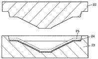
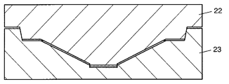
- FIG. 4 is a diagram showing a molding machine constituted by a first mold and a second mold for forming the speaker diaphragm in the first embodiment of the present invention.
- the first mold 22 has a truncated cone shape having a mold protruding downward
- the second mold 23 has a truncated cone shape of the first mold 22. It is a dish shape to be fitted.
- the first mold 22 and the second mold 23 are provided with heaters for heating.
- FIG. 5 is a cross-sectional view showing a method for manufacturing the speaker diaphragm in accordance with the first exemplary embodiment of the present invention.
- the first mold 22 is pulled upward in the second mold 23.
- a dish-shaped papermaking screen 24 is placed on the second mold 23.
- the papermaking screen 24 is in a state in which pulp as a raw material of the paper layer 7 is scooped up from the pulp solution, and a pulp accumulation layer 25 is formed on the papermaking screen 24 by pulp.
- the thickness of the pulp accumulation layer 25 is approximately 10 mm.
- the heater for heating the second mold 23 is driven to heat and evaporate the moisture contained in the pulp accumulation layer 25.
- the pulp deposit layer 25 is not compressed by the first mold 22 and the second mold 23. That is, the pulp accumulation layer 25 is heated and dried in a non-pressurized state.
- the heater for heating attached to the second mold 23 is driven, but not only the heater for heating embedded in the second mold 23 is used.
- a heater for heating attached to one mold 22 may be driven simultaneously.
- the pulp accumulation layer 25 may be dried with warm air such as a dryer, or may be naturally dried without driving a heater for heating.
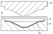
- FIG. 6 is a cross-sectional view of the raw material of the speaker diaphragm in the first exemplary embodiment of the present invention.
- the pulp accumulation layer 25 when the pulp accumulation layer 25 is heated and dried in a non-pressurized state, the pulp accumulation layer 25 is dried while being scooped up from the pulp solution.
- the pulp on the surface facing the mold 22 has a large number of fluff 25a and is fluffy.
- the pulp in the pulp accumulation layer 25 is further fluffed by lightly applying a wire brush or the like to the dried pulp accumulation layer 25.
- FIG. 7 is a cross-sectional view showing a method for manufacturing the speaker diaphragm in accordance with the first exemplary embodiment of the present invention.
- the flat woven fabric 26 before embossing is arranged between the first mold 22 and the second mold 23 on which the pulp accumulation layer 25 and the papermaking screen 24 are placed.
- the flat woven fabric 26 is a member corresponding to the woven fabric layer 6 after molding, and is formed by weaving yarns in a lattice shape.
- the flat woven fabric 26 is pre-impregnated with a thermosetting resin containing at least one of a phenol resin, an acrylic resin, an epoxy resin, and a vinyl ester resin thermosetting resin.
- FIG. 8 is a cross-sectional view showing a method for manufacturing the speaker diaphragm in accordance with the first exemplary embodiment of the present invention.
- the first mold 22 is pushed down to the second mold 23, and the pulp accumulation layer 25 and the flat woven fabric 26 are pressurized and compressed.
- the fluff 25a shown in FIG. 6 enters the stitch of the flat woven fabric 26 and protrudes from the surface of the flat woven fabric 26. And then compressed. That is, the pulp accumulation layer 25 and the flat woven fabric 26 are clamped in a state where the fluff 25a of the pulp accumulation layer 25 is filled with the stitches of the flat woven fabric 26.
- the pulp accumulation layer 25 and the flat woven fabric 26 are deformed by pressurization and compression, and become the shapes of the paper layer 7 and the woven fabric layer 6 of the speaker diaphragm 5 shown in FIG. 1B, respectively.
- the first mold 22 and the second mold 23 are heated to 180 to 250 degrees to impregnate the flat woven fabric 26.
- the cured thermosetting resin is thermoset to integrate the pulp accumulation layer 25 and the flat woven fabric 26.
- the first mold 22 and the second mold 23 are opened, the molded speaker diaphragm 5 is taken out, and the papermaking screen 24 is peeled off.
- the mold was clamped with the pulp deposition layer 25 and the papermaking screen 24 placed on the second mold 23, but after the pulp deposition layer 25 was dried by heating, the papermaking screen 24 was peeled off, Only the flat woven fabric 26 and the pulp accumulation layer 25 may be clamped.
- the speaker diaphragm 5 according to the first embodiment of the present invention is formed.
- the fluff 25a on the surface of the pulp accumulation layer 25 facing the first mold 22 is filled into the stitches of the flat woven fabric 26. And can be compression molded in a state of protruding from the surface of the flat woven fabric 26. Then, as shown in FIGS. 1A and 1B, the speaker diaphragm 5 having a configuration in which the fluff 7 a is entangled with the woven yarn 9 and fixed with a thermosetting resin can be formed from the surface side of the woven fabric layer 6. it can.
- the pulp accumulation layer 25 may be fluffed by brushing with a wire brush or a coarse paper basket. In this way, if the pulp accumulation layer 25 is further fluffed, more fluff 25a can enter into the texture of the flat woven fabric 26, and the paper layer in the stitch 10 in the speaker diaphragm 5 after manufacture. 7 can be increased, and the fluff 7a of the paper layer 7 can be entangled with the woven yarn 9.
- the pulp that is the raw material of the paper layer 7 has fibers having a fibril structure such as animal hair fibers such as wool, bast fibers such as hemp, and seed hair fibers such as cotton and kapok. May be mixed. That is, when fibers having a structure in which ultrafine fiber elements are bundled like a fibril structure are mixed, the fibers are cracked during drying, and the pulp accumulation layer 25 is further fluffed, and more fluff 25a is removed.
- the woven fabric of the flat woven fabric 26 can be made to enter. Furthermore, if the pulp mixed with the fiber having the fibril structure is brushed with a wire brush or a coarse paper basket, it can be made more fluffy.
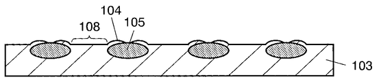
- FIG. 9A is a perspective view of the speaker diaphragm according to the second exemplary embodiment of the present invention.
- the speaker diaphragm 101 has a two-layer structure of a woven fabric layer 102 and a nonwoven fabric layer 103, and the fuzz 104 of the nonwoven fabric layer 103 is formed on the woven fabric layer 102 as will be described later. It has an entangled configuration.
- the woven fabric layer 102 is formed by weaving two kinds of woven yarns 107 of warp yarns 105 and weft yarns 106 in a lattice pattern. The lattice stripes are formed on the speaker surface when the speaker diaphragm 101 is mounted on the speaker. It appears in the state.
- thermosetting resin (not shown) exists in the inside and the outer periphery of the warp yarn 105 and the weft yarn 106, and when the thermosetting resin is thermally cured, the warp yarn 105 and the weft yarn 106 itself, And the woven fabric layer 102 formed by weaving them is in a cured state.
- the woven fabric layer 102 is configured to contain at least one of high-strength fibers such as aramid fiber, polyester fiber, acrylic fiber, cotton fiber, carbon fiber, glass fiber, silk fiber, and the like as a thermosetting resin.
- aramid fiber such as aramid fiber, polyester fiber, acrylic fiber, cotton fiber, carbon fiber, glass fiber, silk fiber, and the like
- thermosetting resin such as aramid fiber, polyester fiber, acrylic fiber, cotton fiber, carbon fiber, glass fiber, silk fiber, and the like.
- a resin containing at least one of a phenol resin, an acrylic resin, an epoxy resin, and a vinyl ester resin are examples of phenol resin, an acrylic resin, an epoxy resin, and a vinyl ester resin.
- the nonwoven fabric layer 103 is formed by mixing bamboo fiber with a content of 0.5 wt% or more and 20 wt% or less in softwood pulp fiber.
- the bamboo fibers mixed in the nonwoven fabric layer 103 are beaten small until they become a microfibril state, and the average fiber diameter is 5 ⁇ m or less, so that the bamboo fibers are sufficiently entangled with the softwood pulp fibers.
- the nonwoven fabric layer 103 is integrated on the back side of the woven fabric layer 102 by thermocompression bonding. Thus, since the nonwoven fabric layer 103 is thermocompression integrated on the back side of the woven fabric layer 102, air does not pass from the front surface side to the back surface side of the speaker diaphragm 101.
- the bamboo fiber and the softwood pulp fiber constituting the nonwoven fabric layer 103 are filled in a stitch 108 that is a portion surrounded by the adjacent warp yarn 105 and weft yarn 106 of the woven fabric layer 102.
- FIG. 9B is an enlarged view of a main part when the speaker diaphragm according to Embodiment 1 of the present invention is viewed from the surface side.
- the bamboo fiber and the softwood pulp fiber fluff 104 of the nonwoven fabric layer 103 are entangled with the warp yarn 105 and the weft yarn 106 from the surface side of the woven fabric layer 102 (the side opposite to the joint surface with the nonwoven fabric layer 103), It has a structure cured with a thermosetting resin together with the woven yarn 107. That is, in the speaker diaphragm 101, the thermosetting resin is cured by heat and the woven fabric layer 102 and the nonwoven fabric layer 103 are integrated by pressure bonding.
- the woven fabric layer 102 and the nonwoven fabric layer 103 are made of bamboo fiber. Crimping is integrated. Strictly speaking, the stitch 108 refers to a substantially rectangular parallelepiped portion whose bottom surface is the surface surrounded by the warp yarn 105 and the weft yarn 106.
- FIG. 10 is a schematic sectional view taken along the broken line 10-10 in FIG. 9B.
- the stitches 108 between the warp yarns 105 are filled with bamboo fibers and softwood pulp fibers of the nonwoven fabric layer 103, and the bamboo fibers and softwood pulp fiber fluff 104 of the nonwoven fabric layer 103.
- the state where the fluff 104 is entangled with the warp yarn 105 has been described.
- the fluff 104 is entangled similarly to the warp thread 105.
- FIG. 11 is a cross-sectional view of a speaker using the speaker diaphragm according to the second embodiment of the present invention.
- a speaker 111 includes a magnetic circuit 113 having a cylindrical magnetic gap 112, and a cylindrical voice coil body 115 in which a coil 114 portion is movably disposed in the magnetic gap 112. .
- the inner peripheral portion of the cone-shaped speaker diaphragm 101 is connected to the outer peripheral portion near the upper end of the voice coil body 115, and the outer peripheral portion of the speaker diaphragm 101 is a ring-shaped first edge 116. Is connected to the upper surface opening portion of the deep dish-shaped frame 117.
- a hemispherical dust cap 118 is provided in the vicinity of the inner peripheral portion of the speaker diaphragm 101 so as to cover the upper surface side of the voice coil body 115. It has a function to prevent intrusion of moisture and the like.
- the lead wire 119 from the coil 114 of the voice coil body 115 is led out of the frame 117 from the upper part of the voice coil body 115 in a non-contact state with the speaker diaphragm 101.
- An AC current to which an audio signal is added is sent from the outside of the speaker to the coil 114 via the lead line 119.
- the inner peripheral end of the second edge 120 having a ring-shaped planar shape formed by an elastic body is formed between the lead wire 119 lead portion and the magnetic gap 112 placement portion of the voice coil body 115.
- the suspension holder 121 is connected. Further, the other end side of the second edge 120 is coupled to an inner surface intermediate portion of the frame 117.
- the second edge 120 and the first edge 116 are formed of an elastic body such as urethane or rubber, but the second edge 120 is downward, and the first edge 116 is upward.
- the shape protrudes in the opposite direction.
- the operation of the speaker diaphragm 101 is also symmetric in the upward and downward directions, and as a result, distortion included in the sound reproduced from the speaker 111 can be reduced.
- the voice coil body 115 reacts with the magnetic field formed by the magnetic gap 112 and a driving force is generated in the voice coil body 115.
- This driving direction follows the Fleming left-hand rule, and the voice coil body 115 fluctuates in the vertical direction. Due to the fluctuation of the voice coil body 115, the speaker diaphragm 101 whose inner peripheral portion is connected to the voice coil body 115 similarly vibrates in the vertical direction, and sound is generated from the speaker 111 by moving the air. It is a mechanism.
- the speaker diaphragm is formed by overlapping members such as woven fabric and paper, these members cannot be sufficiently integrated because they have different properties. As a result, it is difficult for the speaker diaphragm having such a configuration to maximize the high Young's modulus of the woven fabric layer fixed with the thermosetting resin and the large internal loss of the non-woven fabric layer. The improvement was not enough.
- the speaker diaphragm 101 according to Embodiment 2 of the present invention has a configuration in which bamboo fibers are mixed into the nonwoven fabric layer 103.
- the bamboo fibers have a characteristic of high rigidity and toughness, so that the bamboo fibers tend to stand on the surface of the nonwoven fabric layer 103. .
- many fluffs 104 are formed on the surface of the nonwoven fabric layer 103 made of bamboo fibers, and the fluffs 104 are filled in the stitches 108 of the woven fabric layer 102.
- fuzz 104 is filled in the stitch 108 of the woven fabric layer 102, and further, the fuzz 104 is entangled with the woven yarn 107 of the woven fabric layer 102. Therefore, the woven fabric layer 102 and the nonwoven fabric layer 103 are firmly integrated.
- the speaker diaphragm 101 generally has a configuration in which only the back surface side of the woven fabric layer 102 is bonded to the layer of the nonwoven fabric layer 103 (see FIG. 17), the woven fabric layer 102 and the nonwoven fabric layer 103 are sufficiently integrated.
- the excellent Young's modulus of the woven fabric layer and the excellent interior of the nonwoven fabric layer The loss can be fully exploited.
- the Young's modulus of speaker diaphragm 101 can be further increased by the rigidity and toughness of bamboo fiber itself.
- the speaker diaphragm 101 according to Embodiment 2 of the present invention can increase internal loss and Young's modulus, and can improve the sound quality of the speaker 111.
- woven fabric layer 102 and nonwoven fabric layer 103 can be firmly integrated. The possibility of peeling off can be made extremely low.
- the speaker diaphragm 101 according to the second embodiment of the present invention using bamboo fiber as a material to be mixed into the nonwoven fabric layer 103 is excellent in terms of cost and environment.
- conifers that have been used as materials for conventional speaker diaphragms are harvested around the world for a variety of uses other than speaker diaphragms, there is currently a concern that there will be a shortage of conifers. It is in.
- bamboo is present more in Asia than in conifers, and its growth rate is very fast. Based on such a situation, in Embodiment 2 of the present invention, bamboo fibers are mixed into the nonwoven fabric layer 103, and the ratio of the softwood pulp fibers in the nonwoven fabric layer 103 is reduced. As a result, the speaker diaphragm 101 according to the second embodiment of the present invention can be manufactured at a low cost and without adversely affecting the environment.
- the bamboo fibers mixed in the nonwoven fabric layer 103 are in a microfibril state with an average fiber diameter of 5 ⁇ m or less by beating.
- the bamboo fiber to be mixed is in a microfibril state, the entanglement between the bamboo fiber and the softwood pulp fiber can be improved, and the Young's modulus of the speaker diaphragm can be improved.
- the average fiber diameter of the bamboo fiber mixed in the nonwoven fabric layer 103 was 5 micrometers or less, it is not restricted to this, You may make the average fiber diameter of bamboo fiber 5 micrometers or more.
- the average fiber diameter of the bamboo fibers is 5 ⁇ m or more, the force for strengthening the entanglement between the bamboo fibers and the softwood pulp fibers is reduced as compared with the case where the average fiber diameter is 5 ⁇ m or less.
- the nonwoven fabric layer 103 may be formed only of bamboo fibers, and the speaker diaphragm 101 may be formed. In this case, the inherent properties of the bamboo fiber are exhibited, that is, the rigidity and toughness of the bamboo fiber can make the Young's modulus higher than that of the conventional speaker diaphragm.
- thermosetting resin included in the woven fabric layer 102 it is desirable to use a resin containing at least one of a phenol resin, an acrylic resin, an epoxy resin, and a vinyl ester resin as the thermosetting resin included in the woven fabric layer 102.
- a resin containing these resins can be sufficiently cured during thermocompression bonding to increase the hardness of the speaker diaphragm 101 and increase the Young's modulus of the speaker diaphragm 101.
- aramid fibers may be mixed in the nonwoven fabric layer 103.
- the strength of the speaker diaphragm 101 can be increased, and the hardness of the speaker diaphragm 101 is increased accordingly, and thus the Young's modulus is further increased. be able to.
- Even when aramid fibers are mixed in this way if the bamboo fibers are beaten to the microfibril state, the bamboo fibers can be sufficiently entangled with the aramid fibers, and the properties of the bamboo fibers can be exhibited. .
- the woven fabric layer 102 it is desirable to use a woven fabric containing at least one of hard fibers such as aramid fiber, polyester fiber, acrylic fiber, cotton fiber, carbon fiber, glass fiber, and silk fiber. . If a woven fabric containing these fibers is used, the hardness of the woven fabric layer 102 can be improved and the Young's modulus of the speaker diaphragm 101 can be increased.
- hard fibers such as aramid fiber, polyester fiber, acrylic fiber, cotton fiber, carbon fiber, glass fiber, and silk fiber.
- the woven fabric layer 102 has a lattice pattern exposed on the surface of the speaker.
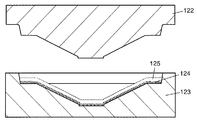
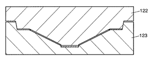
- FIG. 12 is a view showing a molding machine constituted by a first mold and a second mold for forming the speaker diaphragm in the second embodiment of the present invention.
- the first mold 122 has a truncated cone shape having a mold protruding downward
- the second mold 123 has a truncated cone shape of the first mold 122. It is a dish shape to be fitted.
- the first mold 122 and the second mold 123 are provided with heaters for heating.
- FIG. 13 is a cross-sectional view showing a method for manufacturing the speaker diaphragm in accordance with the second exemplary embodiment of the present invention.
- the first mold 122 is pulled upward in the second mold 123.
- a dish-shaped papermaking screen 124 is placed on the second mold 123.
- the papermaking screen 124 is in a state in which softwood pulp fibers and bamboo fibers, which are raw materials of the nonwoven fabric layer 103, are scooped up from the dissolution tank, and the thickness made up of the fibers and bamboo fibers is about 10 mm on the papermaking screen 124.
- a deposited layer 125 is formed.
- the bamboo fibers in a fibrillated state are evenly mixed in the dissolution tank, the bamboo fibers are evenly present in the deposition layer 125 and are randomly oriented. Further, the amount of bamboo fiber mixed in the dissolution tank is adjusted so that the bamboo fiber becomes 0.5 wt% or more and 20 wt% or less when the moisture of the deposition layer 125 is evaporated.
- the heater for heating the second mold 123 is driven to heat and evaporate the moisture contained in the deposited layer 125.
- the deposited layer 125 is not compressed by the first mold 122 and the second mold 123. That is, the deposited layer 125 is heated and dried in a non-pressurized state.
- the heater for heating attached to the second mold 123 is driven, but not only the heater for heating embedded in the second mold 123 is used. Heating heaters attached to one mold 122 may be driven simultaneously.
- the deposited layer 125 may be dried with warm air such as a dryer without driving a heater for heating, or may be naturally dried.
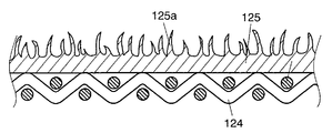
- FIG. 14 is a cross-sectional view of the raw material of the speaker diaphragm in accordance with the second exemplary embodiment of the present invention.
- the deposited layer 125 when the deposited layer 125 is heated and dried in a non-pressurized state, the deposited layer 125 is dried while being scooped up from the pulp solution. Therefore, the first mold 122 of the deposited layer 125 after drying A large number of fluffs 125a made of bamboo fibers and softwood pulp fibers are generated on the opposite surfaces, and the surface of the deposited layer 125 is fluffy.
- the bamboo fiber fluff 125a stands up against the surface of the deposited layer 125 as compared with the softwood pulp fiber.
- softwood pulp fibers tend to be laid on the surface of the deposited layer 125 after drying and arranged in a direction along the surface of the deposited layer 125 (a state lying on the surface), whereas bamboo fibers are coniferous.
- it has a tendency to easily maintain the state before drying because it has higher rigidity and toughness than pulp fiber. That is, on the surface of the deposited layer 125 before drying, the bamboo fibers that have been oriented in directions other than the direction along the surface are maintained as they are when heated and dried, and as a result, on the surface of the deposited layer 125 after drying. It becomes a standing state.
- the bamboo fibers present on the surface of the deposited layer 125 and oriented in directions other than the direction along the surface of the deposited layer 125 are fluffed after drying. 125a.
- FIG. 15 is a cross-sectional view showing a method for manufacturing the speaker diaphragm in accordance with the second exemplary embodiment of the present invention.
- the flat woven fabric 126 before embossing is disposed between the first mold 122 and the second mold 123 on which the deposition layer 125 and the papermaking screen 124 are placed.
- the flat woven fabric 126 is a member corresponding to the woven fabric layer 102 after molding, and is formed by weaving yarns in a lattice shape.
- the flat woven fabric 126 is pre-impregnated with a thermosetting resin containing at least one of a phenol resin, an acrylic resin, an epoxy resin, and a vinyl ester resin thermosetting resin.
- FIG. 16 is a cross-sectional view showing a method for manufacturing the speaker diaphragm in the second embodiment of the present invention.
- the first mold 122 is pushed down to the second mold 123, and the deposited layer 125 and the flat woven fabric 126 are pressurized and compressed.
- the bamboo fibers and softwood pulp fibers of the deposited layer 125 were fluffy, so the fluff 125a shown in FIG. 14 enters the stitches of the flat woven fabric 126 and protrudes from the surface of the flat woven fabric 126. And then compressed. That is, the deposition layer 125 and the flat woven fabric 126 are clamped in a state where the fluff 125a of the bamboo fiber and the softwood pulp fiber of the deposited layer 125 fills the stitches of the flat woven fabric 126.
- the deposited layer 125 and the flat woven fabric 126 are deformed by pressurization and compression, and become the shape of the nonwoven fabric layer 103 and the woven fabric layer 102 of the speaker diaphragm 101 shown in FIG. 9A, respectively.
- the first mold 122 and the second mold 123 are heated to 180 to 250 degrees to impregnate the flat woven cloth 126.
- the thermosetting resin thus obtained is thermally cured to integrate the deposition layer 125 and the flat woven fabric 126. That is, the deposited layer 125 and the flat woven fabric 126 are integrated by applying heat, and the fuzz 125 a is also integrated by being intertwined with the flat woven fabric 126.
- the mold 122 and the second mold 123 are opened, the molded speaker diaphragm 101 is taken out, and the papermaking screen 124 is peeled off.
- the mold is clamped with the deposition layer 125 and the papermaking screen 124 placed on the second mold 123.
- the papermaking screen 124 is peeled off to form a flat plate shape. Only the woven fabric 126 and the deposited layer 125 may be clamped.
- the speaker diaphragm 101 according to the second embodiment of the present invention is formed.
- the fluff 125a on the surface of the deposition layer 125 facing the first mold 122 is filled into the stitches of the flat woven fabric 126. Further, it can be compression-molded in a state of protruding from the surface of the flat woven fabric 26. Then, as shown in FIGS. 9A and 9B, the speaker vibration having a configuration in which the fluff 104 made of bamboo fiber and softwood pulp fiber is entangled with the woven yarn 107 and fixed with a thermosetting resin from the surface side of the woven fabric layer 102. A plate 101 can be formed.
- the speaker diaphragm according to the present invention has a configuration in which the fluff of the paper layer is entangled with the weaving yarn from the surface side of the woven fabric layer and fixed with a thermosetting resin, and the paper layer and the woven fabric layer are integrated.
- the internal loss and Young's modulus of the speaker diaphragm can be increased.
- the speaker diaphragm according to the present invention has a configuration in which bamboo fibers are mixed in the nonwoven fabric layer, and the surface of the woven fabric layer is filled with the fluff by the bamboo fibers in addition to the fluff by the nonwoven fabric layer in the knitted fabric layer. Since these fluffs are entangled from the side, the woven fabric layer and the nonwoven fabric layer can be sufficiently integrated, and the internal loss and Young's modulus of the speaker diaphragm can be increased.
- the speaker diaphragm in the present invention can improve the sound quality of the speaker and is useful in various acoustic devices.
Landscapes
- Engineering & Computer Science (AREA)
- Physics & Mathematics (AREA)
- Acoustics & Sound (AREA)
- Signal Processing (AREA)
- Multimedia (AREA)
- Manufacturing & Machinery (AREA)
- Diaphragms For Electromechanical Transducers (AREA)
Abstract
La présente invention concerne une membrane de haut-parleur dotée d'une couche d'étoffe tissée imprégnée d'une résine thermodurcissable qui est durcie thermiquement et d'une couche de papier incorporée par stratification sur la face arrière de la couche d'étoffe tissée. Comme le duvet de la couche de papier qui comble le maillage de la couche d'étoffe tissée s'entrelace avec les fils de la couche d'étoffe tissée provenant du côté surface avant de la couche d'étoffe tissée et est fixé par la résine thermodurcissable, la couche de papier remplit et est incorporée dans le maillage de la couche d'étoffe tissée de telle sorte que les pertes internes et le module de Young de la membrane de haut-parleur puissent être accrus. La qualité sonore du haut-parleur s'en trouve ainsi améliorée.
Priority Applications (3)
| Application Number | Priority Date | Filing Date | Title |
|---|---|---|---|
| US12/863,852 US8824725B2 (en) | 2008-01-22 | 2009-01-21 | Speaker diaphragm, speaker using said diaphragm, and speaker diaphragm manufacturing method |
| EP09704280.8A EP2234408A4 (fr) | 2008-01-22 | 2009-01-21 | Membrane de haut-parleur, haut-parleur utilisant ladite membrane et procédé de fabrication d'une membrane de haut-parleur |
| CN200980103172.9A CN101926183B (zh) | 2008-01-22 | 2009-01-21 | 扬声器用振动板、使用它的扬声器以及扬声器用振动板的制造方法 |
Applications Claiming Priority (4)
| Application Number | Priority Date | Filing Date | Title |
|---|---|---|---|
| JP2008-011252 | 2008-01-22 | ||
| JP2008011252A JP5125540B2 (ja) | 2008-01-22 | 2008-01-22 | スピーカ用振動板及びそれを用いたスピーカ |
| JP2008082796A JP5125677B2 (ja) | 2008-03-27 | 2008-03-27 | スピーカ用振動板及びそれを用いたスピーカとスピーカ用振動板の製造方法 |
| JP2008-082796 | 2008-03-27 |
Publications (1)
| Publication Number | Publication Date |
|---|---|
| WO2009093444A1 true WO2009093444A1 (fr) | 2009-07-30 |
Family
ID=40900956
Family Applications (1)
| Application Number | Title | Priority Date | Filing Date |
|---|---|---|---|
| PCT/JP2009/000193 WO2009093444A1 (fr) | 2008-01-22 | 2009-01-21 | Membrane de haut-parleur, haut-parleur utilisant ladite membrane et procédé de fabrication d'une membrane de haut-parleur |
Country Status (4)
| Country | Link |
|---|---|
| US (1) | US8824725B2 (fr) |
| EP (1) | EP2234408A4 (fr) |
| CN (1) | CN101926183B (fr) |
| WO (1) | WO2009093444A1 (fr) |
Cited By (2)
| Publication number | Priority date | Publication date | Assignee | Title |
|---|---|---|---|---|
| US8824725B2 (en) | 2008-01-22 | 2014-09-02 | Panasonic Corporation | Speaker diaphragm, speaker using said diaphragm, and speaker diaphragm manufacturing method |
| CN104320733A (zh) * | 2014-09-30 | 2015-01-28 | 陈正盛 | 一种结构体及使用该结构体的耳机和音箱 |
Families Citing this family (15)
| Publication number | Priority date | Publication date | Assignee | Title |
|---|---|---|---|---|
| WO2008084641A1 (fr) * | 2006-12-22 | 2008-07-17 | Panasonic Corporation | Diaphragme, cadre et calotte pare-poussière pour haut-parleur, haut-parleur et appareil les utilisant, et procédé de fabrication d'un composant pour haut-parleur |
| JP4867774B2 (ja) * | 2007-04-26 | 2012-02-01 | パナソニック株式会社 | スピーカ |
| CN102118672A (zh) * | 2011-03-28 | 2011-07-06 | 苏州上声电子有限公司 | 扬声器振动膜片及扬声器 |
| WO2012140880A1 (fr) * | 2011-04-15 | 2012-10-18 | パナソニック株式会社 | Pièce moulée en résine pour haut-parleurs et haut-parleur doté de celle-ci et dispositif électronique et dispositif mobile dotés chacun dudit haut-parleur |
| US9521490B2 (en) * | 2012-03-14 | 2016-12-13 | Pioneer Corporation | Speaker diaphragm and production method for speaker diaphragm |
| JPWO2014132393A1 (ja) * | 2013-02-28 | 2017-02-02 | パイオニア株式会社 | スピーカ用振動板 |
| US9485586B2 (en) | 2013-03-15 | 2016-11-01 | Jeffery K Permanian | Speaker driver |
| JP6500236B2 (ja) * | 2013-07-25 | 2019-04-17 | パナソニックIpマネジメント株式会社 | ラウドスピーカ用振動板と、その振動板を用いたラウドスピーカ、および電子機器と、移動体装置 |
| US9781515B2 (en) * | 2014-09-08 | 2017-10-03 | Panasonic Intellectual Property Management Co., Ltd. | Loudspeaker diaphragm, and loudspeaker, electronic device and mobile device including the diaphragm |
| CN104703100A (zh) * | 2015-03-11 | 2015-06-10 | 歌尔声学股份有限公司 | 一种振膜以及一种扬声器装置 |
| CN105430560A (zh) * | 2015-12-29 | 2016-03-23 | 常熟市先锋乐器有限公司 | 一种多媒体音箱 |
| CN105554645A (zh) * | 2016-01-01 | 2016-05-04 | 苏州井利电子股份有限公司 | 一种用于扬声器的耐湿性振动板 |
| CN105554644A (zh) * | 2016-01-01 | 2016-05-04 | 苏州井利电子股份有限公司 | 一种用于扬声器的高强度振动板 |
| CN105516865A (zh) * | 2016-01-01 | 2016-04-20 | 苏州井利电子股份有限公司 | 一种用于扬声器的耐水性振动板 |
| CN111910462B (zh) * | 2020-08-06 | 2022-12-06 | 国光电器股份有限公司 | 一种含碳纤维的扬声器用纸盆及其制备方法 |
Citations (5)
| Publication number | Priority date | Publication date | Assignee | Title |
|---|---|---|---|---|
| JPS5395617A (en) * | 1977-02-01 | 1978-08-22 | Matsushita Electric Ind Co Ltd | Acoustic diapharagm |
| JPS59106289U (ja) * | 1983-01-06 | 1984-07-17 | 株式会社ケンウッド | スピ−カの振動板 |
| JPH04367198A (ja) * | 1991-06-13 | 1992-12-18 | Pioneer Electron Corp | スピーカ用振動板 |
| JP2003219493A (ja) | 2002-01-25 | 2003-07-31 | Onkyo Corp | スピーカー用振動板 |
| JP2005080098A (ja) * | 2003-09-02 | 2005-03-24 | Pioneer Electronic Corp | スピーカ用の振動板及びそれを備えたスピーカ |
Family Cites Families (12)
| Publication number | Priority date | Publication date | Assignee | Title |
|---|---|---|---|---|
| DE744286C (de) | 1937-03-02 | 1944-01-13 | Siemens Ag | Aus Faserstoffbrei durch Tauchen oder Giessen hergestellte Membran fuer elektroakustische Geraete |
| JPS5853298A (ja) | 1981-09-25 | 1983-03-29 | Toray Ind Inc | 音響機器用振動板およびその製造方法 |
| JPS6047391U (ja) | 1983-09-08 | 1985-04-03 | ヤマハ株式会社 | スピ−カ振動板 |
| US5031720A (en) | 1987-12-01 | 1991-07-16 | Kabushiki Kaisha Kenwood | Speaker diaphragm |
| US5274199A (en) * | 1990-05-18 | 1993-12-28 | Sony Corporation | Acoustic diaphragm and method for producing same |
| JP2667745B2 (ja) * | 1991-03-11 | 1997-10-27 | シャープ株式会社 | 電気音響変換器 |
| JP2002300691A (ja) * | 2001-04-02 | 2002-10-11 | Tohoku Pioneer Corp | スピーカ用振動板およびその製造方法 |
| KR100534525B1 (ko) * | 2002-02-01 | 2005-12-07 | 주식회사 코오롱 | 저신장성 및 유연성이 우수한 인공피혁용 복합시트 |
| US7467686B2 (en) * | 2003-02-19 | 2008-12-23 | Victor Company Of Japan, Limited | Speaker diaphragms, manufacturing methods of the same, and dynamic speakers |
| JP2006222756A (ja) * | 2005-02-10 | 2006-08-24 | Pioneer Electronic Corp | 振動板、および、スピーカ装置 |
| JP2006325125A (ja) * | 2005-05-20 | 2006-11-30 | Pioneer Electronic Corp | スピーカ用振動板及びその製造方法 |
| US8824725B2 (en) | 2008-01-22 | 2014-09-02 | Panasonic Corporation | Speaker diaphragm, speaker using said diaphragm, and speaker diaphragm manufacturing method |
-
2009
- 2009-01-21 US US12/863,852 patent/US8824725B2/en active Active
- 2009-01-21 WO PCT/JP2009/000193 patent/WO2009093444A1/fr active Application Filing
- 2009-01-21 EP EP09704280.8A patent/EP2234408A4/fr not_active Withdrawn
- 2009-01-21 CN CN200980103172.9A patent/CN101926183B/zh active Active
Patent Citations (5)
| Publication number | Priority date | Publication date | Assignee | Title |
|---|---|---|---|---|
| JPS5395617A (en) * | 1977-02-01 | 1978-08-22 | Matsushita Electric Ind Co Ltd | Acoustic diapharagm |
| JPS59106289U (ja) * | 1983-01-06 | 1984-07-17 | 株式会社ケンウッド | スピ−カの振動板 |
| JPH04367198A (ja) * | 1991-06-13 | 1992-12-18 | Pioneer Electron Corp | スピーカ用振動板 |
| JP2003219493A (ja) | 2002-01-25 | 2003-07-31 | Onkyo Corp | スピーカー用振動板 |
| JP2005080098A (ja) * | 2003-09-02 | 2005-03-24 | Pioneer Electronic Corp | スピーカ用の振動板及びそれを備えたスピーカ |
Non-Patent Citations (1)
| Title |
|---|
| See also references of EP2234408A4 * |
Cited By (2)
| Publication number | Priority date | Publication date | Assignee | Title |
|---|---|---|---|---|
| US8824725B2 (en) | 2008-01-22 | 2014-09-02 | Panasonic Corporation | Speaker diaphragm, speaker using said diaphragm, and speaker diaphragm manufacturing method |
| CN104320733A (zh) * | 2014-09-30 | 2015-01-28 | 陈正盛 | 一种结构体及使用该结构体的耳机和音箱 |
Also Published As
| Publication number | Publication date |
|---|---|
| EP2234408A4 (fr) | 2013-09-25 |
| CN101926183B (zh) | 2013-09-11 |
| CN101926183A (zh) | 2010-12-22 |
| US20100296688A1 (en) | 2010-11-25 |
| US8824725B2 (en) | 2014-09-02 |
| EP2234408A1 (fr) | 2010-09-29 |
Similar Documents
| Publication | Publication Date | Title |
|---|---|---|
| WO2009093444A1 (fr) | Membrane de haut-parleur, haut-parleur utilisant ladite membrane et procédé de fabrication d'une membrane de haut-parleur | |
| US7344001B2 (en) | Speaker diaphragm and speaker structure | |
| US5878150A (en) | Damper for a loudspeaker and a method for producing the same | |
| US8002079B2 (en) | Diaphragm for speaker, speaker using the diaphragm for speaker, and process for producing the diaphragm for speaker | |
| JP5125677B2 (ja) | スピーカ用振動板及びそれを用いたスピーカとスピーカ用振動板の製造方法 | |
| JP7029602B2 (ja) | スピーカ用振動板とその製造方法およびこれを用いたスピーカ | |
| JP5254119B2 (ja) | スピーカー | |
| JP4419976B2 (ja) | スピーカー振動板およびスピーカー | |
| US20050232458A1 (en) | Speaker-use diaphragm and speaker | |
| US9633648B2 (en) | Loudspeaker membrane and method for manufacturing such a membrane | |
| JP5125540B2 (ja) | スピーカ用振動板及びそれを用いたスピーカ | |
| CN109391879B (zh) | 缝入导线的喇叭振动片及其制造方法 | |
| JP2009027309A (ja) | スピーカ用振動板及びそれを用いたスピーカとこのスピーカ用振動板の製造方法 | |
| JP2009021832A (ja) | スピーカ用振動板とそれを用いたスピーカ | |
| JP3137241B2 (ja) | スピーカー振動板 | |
| JP2015043548A (ja) | スピーカー用振動板及びその製造方法 | |
| JP5158374B2 (ja) | スピーカー | |
| CN109327792B (zh) | 控制特定种类的纤维条数的喇叭振动片及其制造方法 | |
| CN113498008B (zh) | 局部设置有抗噪层的喇叭振动片及其制造方法 | |
| JP3963269B2 (ja) | スピーカー振動板 | |
| TWI723821B (zh) | 局部設置有抗噪層的喇叭振動片及其製造方法 | |
| JP3200762B2 (ja) | 電気音響変換器用振動板 | |
| CN113978048B (zh) | 一种高性能纤维防撕裂无纺布及其制备方法 | |
| JP2009027308A (ja) | スピーカ用振動板及びそれを用いたスピーカとこのスピーカ用振動板の製造方法 | |
| JPH0257096A (ja) | 音響装置用振動板 |
Legal Events
| Date | Code | Title | Description |
|---|---|---|---|
| WWE | Wipo information: entry into national phase |
Ref document number: 200980103172.9 Country of ref document: CN |
|
| 121 | Ep: the epo has been informed by wipo that ep was designated in this application |
Ref document number: 09704280 Country of ref document: EP Kind code of ref document: A1 |
|
| WWE | Wipo information: entry into national phase |
Ref document number: 2009704280 Country of ref document: EP |
|
| WWE | Wipo information: entry into national phase |
Ref document number: 12863852 Country of ref document: US |
|
| NENP | Non-entry into the national phase |
Ref country code: DE |