WO2009084371A1 - めっき触媒吸着方法、金属層付き基板の製造方法及びそれらに用いるめっき触媒液 - Google Patents
めっき触媒吸着方法、金属層付き基板の製造方法及びそれらに用いるめっき触媒液 Download PDFInfo
- Publication number
- WO2009084371A1 WO2009084371A1 PCT/JP2008/072115 JP2008072115W WO2009084371A1 WO 2009084371 A1 WO2009084371 A1 WO 2009084371A1 JP 2008072115 W JP2008072115 W JP 2008072115W WO 2009084371 A1 WO2009084371 A1 WO 2009084371A1
- Authority
- WO
- WIPO (PCT)
- Prior art keywords
- group
- substrate
- plating catalyst
- layer
- catalyst
- Prior art date
Links
- 0 C*CC(C)C(NCOC(NCCOC(C(C)=C)=O)=O)=O Chemical compound C*CC(C)C(NCOC(NCCOC(C(C)=C)=O)=O)=O 0.000 description 3
- QBKVWRZULLCPJU-UHFFFAOYSA-N CCC(C(C)C)C(OCCOC(NCCOC(C=C)=O)=O)=O Chemical compound CCC(C(C)C)C(OCCOC(NCCOC(C=C)=O)=O)=O QBKVWRZULLCPJU-UHFFFAOYSA-N 0.000 description 1
- QGGXGZMUIGAXIX-UHFFFAOYSA-N CCC(C)C(N(CCC#N)CCC#N)=O Chemical compound CCC(C)C(N(CCC#N)CCC#N)=O QGGXGZMUIGAXIX-UHFFFAOYSA-N 0.000 description 1
- DMYZHARVUJKJFG-UHFFFAOYSA-N CCC(CC)C(OCCC#N)=O Chemical compound CCC(CC)C(OCCC#N)=O DMYZHARVUJKJFG-UHFFFAOYSA-N 0.000 description 1
Classifications
-
- C—CHEMISTRY; METALLURGY
- C23—COATING METALLIC MATERIAL; COATING MATERIAL WITH METALLIC MATERIAL; CHEMICAL SURFACE TREATMENT; DIFFUSION TREATMENT OF METALLIC MATERIAL; COATING BY VACUUM EVAPORATION, BY SPUTTERING, BY ION IMPLANTATION OR BY CHEMICAL VAPOUR DEPOSITION, IN GENERAL; INHIBITING CORROSION OF METALLIC MATERIAL OR INCRUSTATION IN GENERAL
- C23C—COATING METALLIC MATERIAL; COATING MATERIAL WITH METALLIC MATERIAL; SURFACE TREATMENT OF METALLIC MATERIAL BY DIFFUSION INTO THE SURFACE, BY CHEMICAL CONVERSION OR SUBSTITUTION; COATING BY VACUUM EVAPORATION, BY SPUTTERING, BY ION IMPLANTATION OR BY CHEMICAL VAPOUR DEPOSITION, IN GENERAL
- C23C18/00—Chemical coating by decomposition of either liquid compounds or solutions of the coating forming compounds, without leaving reaction products of surface material in the coating; Contact plating
- C23C18/16—Chemical coating by decomposition of either liquid compounds or solutions of the coating forming compounds, without leaving reaction products of surface material in the coating; Contact plating by reduction or substitution, e.g. electroless plating
- C23C18/18—Pretreatment of the material to be coated
- C23C18/20—Pretreatment of the material to be coated of organic surfaces, e.g. resins
- C23C18/2006—Pretreatment of the material to be coated of organic surfaces, e.g. resins by other methods than those of C23C18/22 - C23C18/30
- C23C18/2046—Pretreatment of the material to be coated of organic surfaces, e.g. resins by other methods than those of C23C18/22 - C23C18/30 by chemical pretreatment
- C23C18/2073—Multistep pretreatment
- C23C18/2086—Multistep pretreatment with use of organic or inorganic compounds other than metals, first
-
- C—CHEMISTRY; METALLURGY
- C23—COATING METALLIC MATERIAL; COATING MATERIAL WITH METALLIC MATERIAL; CHEMICAL SURFACE TREATMENT; DIFFUSION TREATMENT OF METALLIC MATERIAL; COATING BY VACUUM EVAPORATION, BY SPUTTERING, BY ION IMPLANTATION OR BY CHEMICAL VAPOUR DEPOSITION, IN GENERAL; INHIBITING CORROSION OF METALLIC MATERIAL OR INCRUSTATION IN GENERAL
- C23C—COATING METALLIC MATERIAL; COATING MATERIAL WITH METALLIC MATERIAL; SURFACE TREATMENT OF METALLIC MATERIAL BY DIFFUSION INTO THE SURFACE, BY CHEMICAL CONVERSION OR SUBSTITUTION; COATING BY VACUUM EVAPORATION, BY SPUTTERING, BY ION IMPLANTATION OR BY CHEMICAL VAPOUR DEPOSITION, IN GENERAL
- C23C18/00—Chemical coating by decomposition of either liquid compounds or solutions of the coating forming compounds, without leaving reaction products of surface material in the coating; Contact plating
- C23C18/16—Chemical coating by decomposition of either liquid compounds or solutions of the coating forming compounds, without leaving reaction products of surface material in the coating; Contact plating by reduction or substitution, e.g. electroless plating
- C23C18/1601—Process or apparatus
- C23C18/1603—Process or apparatus coating on selected surface areas
- C23C18/1607—Process or apparatus coating on selected surface areas by direct patterning
- C23C18/1608—Process or apparatus coating on selected surface areas by direct patterning from pretreatment step, i.e. selective pre-treatment
-
- C—CHEMISTRY; METALLURGY
- C23—COATING METALLIC MATERIAL; COATING MATERIAL WITH METALLIC MATERIAL; CHEMICAL SURFACE TREATMENT; DIFFUSION TREATMENT OF METALLIC MATERIAL; COATING BY VACUUM EVAPORATION, BY SPUTTERING, BY ION IMPLANTATION OR BY CHEMICAL VAPOUR DEPOSITION, IN GENERAL; INHIBITING CORROSION OF METALLIC MATERIAL OR INCRUSTATION IN GENERAL
- C23C—COATING METALLIC MATERIAL; COATING MATERIAL WITH METALLIC MATERIAL; SURFACE TREATMENT OF METALLIC MATERIAL BY DIFFUSION INTO THE SURFACE, BY CHEMICAL CONVERSION OR SUBSTITUTION; COATING BY VACUUM EVAPORATION, BY SPUTTERING, BY ION IMPLANTATION OR BY CHEMICAL VAPOUR DEPOSITION, IN GENERAL
- C23C18/00—Chemical coating by decomposition of either liquid compounds or solutions of the coating forming compounds, without leaving reaction products of surface material in the coating; Contact plating
- C23C18/16—Chemical coating by decomposition of either liquid compounds or solutions of the coating forming compounds, without leaving reaction products of surface material in the coating; Contact plating by reduction or substitution, e.g. electroless plating
- C23C18/18—Pretreatment of the material to be coated
- C23C18/20—Pretreatment of the material to be coated of organic surfaces, e.g. resins
- C23C18/28—Sensitising or activating
- C23C18/30—Activating or accelerating or sensitising with palladium or other noble metal
Definitions
- the present invention is suitably used for a plating catalyst adsorption method for efficiently applying a plating catalyst to the surface of a patterned hydrophobic substrate, a method for producing a substrate with a metal layer using the method, and these methods.
- the present invention relates to a plating catalyst solution.
- a metal wiring substrate in which a wiring with a metal pattern is formed on the surface of an insulating substrate has been widely used for electronic components and semiconductor elements.
- a “subtractive method” is mainly used.
- a photosensitive layer that is exposed by irradiation with actinic rays is provided on a metal film formed on the surface of the substrate, the photosensitive layer is exposed imagewise, and then developed to form a resist image.
- the metal film is etched to form a metal pattern, and finally the resist is removed.
- the adhesion between the substrate and the metal film is expressed by an anchor effect generated by providing irregularities on the substrate surface. For this reason, there is a problem that the high frequency characteristics when used as a metal wiring are deteriorated due to the unevenness of the obtained metal pattern at the substrate interface.
- a polymerization initiating group is introduced on the surface of the substrate, a monomer is polymerized from the polymerization initiating group, and a surface graft polymer having a polar group is generated on the substrate surface.
- a method for improving the adhesion between the substrate and the metal film without roughening the surface of the substrate has been proposed (see, for example, Advanced Materials 2000 No. 2081-1494).
- the graft polymer has a polar group, moisture absorption and desorption are likely to occur due to temperature and humidity changes, and as a result, the formed metal film and substrate are deformed. Had.
- Examples of methods for forming metal films on various substrate surfaces include methods using electroless plating and electroplating, and any metal film can be formed by controlling the composition of the plating bath and the plating conditions.
- a resin material for partial plating a heat-sensitive resin composition having a polymerizable group has been proposed (see, for example, JP-A-11-350149).
- this resin material is thermosetting, it is difficult to form fine electric wiring having a line and space of 10 ⁇ m or less, for example, using a full additive method.
- the adhesion of the layers it was difficult to say that the performance was sufficient when applied to electrical wiring.
- a catalyst adsorbing hydrophobic pattern resin layer is formed on a hydrophobic substrate in order to avoid a failure in the electrical wiring manufacturing process due to water absorption or an electrical failure of the electrical wiring itself.
- the method is preferred.
- a plating catalyst adhesion region is formed in a pattern using the difference in the adsorptivity of the plating catalyst between the catalyst-accepting region and the substrate surface not having such characteristics, and then A patterned metal layer can be formed by plating.
- An object of the present invention is to provide a catalyst adsorption method capable of selectively adsorbing a plating catalyst only to a plating catalyst receiving region in a substrate formed with a patterned hydrophobic plating catalyst receiving region on a hydrophobic surface, and
- An object of the present invention is to provide a method for producing a substrate with a metal layer, which is excellent in adhesion between the substrate and the metal layer using the method and can form a high-definition pattern.
- a further object of the present invention is to provide a plating catalyst solution that can be suitably used for the catalyst adsorption method of the present invention and the method for producing a substrate with a metal layer.
- the present inventor has achieved the above object by using a resin composition containing a compound capable of forming an interaction with a plating catalyst or a precursor thereof, and a specific aqueous plating solution.
- the present invention has been completed by finding out what can be achieved. Although the typical aspect of this invention is shown below, this invention is not limited to these.
- Photocuring that contains a compound having a functional group that interacts with a plating catalyst or its precursor and a polymerizable group, and that forms a surface hydrophobic cured product that satisfies the following conditions 1 and 2 by photocuring: Applying a composition on a substrate, A step of exposing to a pattern and curing the photocurable composition to form a surface hydrophobic cured product layer in an exposed region; Removing the uncured product of the photocurable composition with a developer to form a patterned surface hydrophobic cured product layer; And contacting the substrate on which the patterned surface hydrophobic cured product layer is formed with an aqueous plating catalyst solution containing a plating catalyst or a precursor thereof and an organic solvent, When the test liquid containing palladium is brought into contact with the substrate on which the patterned surface hydrophobic cured product layer is formed, the adsorption amount of palladium in the surface hydrophobic cured product layer forming region is Amg / m 2 ,
- Condition 1 Saturated water absorption is 0.01 to 5% by mass in a 25 ° C.-50% relative humidity environment.
- Condition 2 Saturated water absorption is 0.05 to 10% by mass in a 25 ° C.-95% relative humidity environment.
- Photocuring that contains a compound having a functional group that interacts with the plating catalyst or its precursor and a polymerizable group, and that forms a surface hydrophobic cured product that satisfies the following conditions 1 and 2 by photocuring: Applying a composition on a substrate, A step of exposing to a pattern and curing the photocurable composition to form a surface hydrophobic cured product layer in an exposed region; Removing the uncured product of the photocurable composition with a developer to form a patterned surface hydrophobic cured product layer; And contacting the substrate on which the patterned surface hydrophobic cured product layer is formed with an aqueous plating catalyst solution containing a plating catalyst or a precursor thereof and an organic solvent, The solvent of the test solution containing palladium has an absorptance of 3% or more and less than 50% with respect to the mass of the surface hydrophobic cured product layer, and is 0.
- a catalyst adsorption method having an absorption rate of 1% or more and less than 2.0% Saturated water absorption is 0.01 to 5% by mass in a 25 ° C.-50% relative humidity environment.
- Condition 2 Saturated water absorption is 0.05 to 10% by mass in a 25 ° C.-95% relative humidity environment.
- an adhesion auxiliary layer Prior to the step of applying the photocurable composition on a substrate, an adhesion auxiliary layer containing an active species that generates an active site capable of forming an interaction with a film formed of the photocurable composition.
- the compound having a functional group that interacts with the polymerizable group and the plating catalyst or its precursor is a polymer having a functional group that interacts with the polymerizable group and the plating catalyst or its precursor.
- the polymer having a functional group that forms an interaction with the polymerizable group and the plating catalyst or a precursor thereof includes a unit represented by the following formula (1) and a unit represented by the following formula (2). It is a copolymer,
- the catalyst adsorption method as described in ⁇ 8> characterized by the above-mentioned.
- R 1 to R 5 each independently represents a hydrogen atom or an alkyl group
- X, Y and Z each independently represent a single bond
- a divalent organic group, an ester group, an amide group, or an ether group is represented
- L 1 and L 2 each independently represent a divalent organic group.
- ⁇ 14> The method for producing a substrate with a patterned metal layer according to ⁇ 13>, further comprising electroplating.
- An aqueous plating catalyst solution which is used in the catalyst adsorption method according to any one of ⁇ 1> to ⁇ 12> and contains a plating catalyst and a water-soluble organic solvent.
- the plating contained in the catalyst solution A functional group capable of interacting with the plating catalyst or its precursor in which the catalyst or its precursor is introduced into the patterned surface hydrophobic cured product layer, and an aqueous solution having excellent permeability to the surface hydrophobic cured product layer
- the plating catalyst or its precursor permeates and adsorbs selectively and predominantly on the plating catalyst-receptive surface hydrophobic cured product layer forming region.
- the plating catalyst solution itself permeates the surface hydrophobic cured product layer in an amount sufficient to adsorb the plating catalyst or its precursor around the surface, but the surface hydrophobic cured product layer.
- the plating catalyst is adsorbed in a high-definition pattern without complicated processing because it does not penetrate into the unformed region, that is, the exposed portion of the hydrophobic substrate or the adhesion auxiliary layer formed on the surface of the hydrophobic substrate. be able to. Therefore, by using the substrate on which the plating catalyst formed by the method of the present invention is adsorbed in a pattern, a substrate having a high-definition patterned metal layer having excellent adhesion to the substrate can be easily produced. It is considered a thing.
- An object of the present invention is to provide a catalyst adsorption method capable of selectively and predominantly adsorbing a plating catalyst to a plating catalyst receiving region in a substrate formed with a patterned hydrophobic plating catalyst receiving region on a hydrophobic surface
- Another object of the present invention is to provide a method for producing a substrate with a metal layer, which has excellent adhesion between the substrate formed by using the method and the metal layer and can form a high-definition pattern.
- a further object of the present invention is to provide a plating solution that can be suitably used in the catalyst adsorption method of the present invention and the method for producing a substrate with a metal layer.
- the catalyst adsorption method according to the aspect ⁇ 1> of the present invention includes (1) a compound having a functional group that interacts with a plating catalyst or a precursor thereof and a polymerizable group, and forms a hydrophobic surface.
- Step of applying photocurable composition on substrate (2) Exposing in a pattern through a mask, curing the photocurable composition, and exposing the surface hydrophobic cured product layer to the exposed region
- a step (second step) (3) a step of removing the uncured product of the photocurable composition with a developer to form a patterned surface hydrophobic cured product layer (third step), and And (4) a step (fourth step) of bringing a plating catalyst or a precursor thereof and an aqueous plating catalyst solution containing an organic solvent into contact with the substrate on which the patterned surface hydrophobic cured product layer is formed. It is characterized by.
- a test solution containing palladium was formed on the patterned surface hydrophobic cured product layer.
- the amount of adsorption of palladium in the surface hydrophobic cured product layer forming region when contacted with the substrate is Amg / m 2 and the amount of palladium adsorption in the surface hydrophobic cured product layer non-formed region is Bmg / m 2 .
- the following relational expressions (A) and (B) may be satisfied.
- the surface hydrophobic cured product layer that achieves the above-described adsorption amount can achieve the excellent effect of the present invention in any of the various plating catalyst solutions described later.
- the physical properties of the surface of the surface hydrophobic cured product layer formed by curing the photocurable composition satisfy both the following conditions 1 and 2.
- Condition 1 Saturated water absorption is 0.01 to 5% by mass in a 25 ° C.-50% relative humidity environment.
- Condition 2 Saturated water absorption is 0.05 to 10% by mass in a 25 ° C.-95% relative humidity environment.
- the plating catalyst solution preferably permeates selectively and predominantly into the surface hydrophobic cured product layer.
- the plating catalyst solution or a precursor thereof contained in the plating catalyst solution may be in an amount sufficient to adsorb, and is not necessarily an area where the plating catalyst or the precursor thereof does not function effectively in the subsequent plating, that is, the It is not necessary to penetrate to the deepest part of the cured product layer.
- the permeation performance of the plating catalyst solution can be determined by a plating catalyst solution containing palladium as a plating catalyst, that is, a test solution containing palladium, if attention is paid to the absorption rate with respect to the surface hydrophobic cured product layer.
- the solvent of the test solution containing palladium has an absorptance of 3% or more and less than 50% with respect to the weight of the surface hydrophobic cured product layer, and the weight of the region where the surface hydrophobic cured product layer is not formed. It is sufficient that the absorption rate is 0.1% or more and less than 2.0%.
- the solvent of the plating catalyst solution containing palladium as the plating catalyst is the surface hydrophobic hardening of the palladium catalyst.
- a photocurable composition capable of forming a receptive cured product layer of the plating catalyst or its precursor is applied on the substrate.
- a photocurable composition contains the compound which has a functional group and polymeric group which form an interaction with a plating catalyst or its precursor. This functional group is a group that can interact with the plating catalyst or its precursor even after the photocuring step.
- a photosensitive resin composition In the photosensitive resin composition, a functional group that forms an interaction with a plating catalyst or a precursor thereof capable of forming a graft polymer by a surface graft polymerization method (hereinafter, such a functional group is appropriately referred to as “interactive property”. And a compound having a polymerizable group (hereinafter referred to as a specific polymerizable compound as appropriate).
- a compound having an interactive group and a polymerizable group in the present invention it is preferable to use a compound having a polymerizable group and an interactive group, low water absorption, and high hydrophobicity.
- the interactive group in the specific polymerizable compound is preferably a non-dissociable functional group
- the non-dissociable functional group means a functional group that does not generate a proton upon dissociation.
- a functional group has a function of forming an interaction with the plating catalyst or its precursor, but does not have high water absorption and hydrophilicity like a dissociative polar group (hydrophilic group).
- the resin coating film formed from the polymerizable compound having a functional group can form a hydrophobic coating film that is difficult for an alkali developer or the like to penetrate.
- the polymerizable group that the specific polymerizable compound has is a functional group in which a compound having a polymerizable group and an interactive group or a substrate and a compound having a polymerizable group and an interactive group are bonded to each other by energy application.
- the interactive group possessed by the specific polymerizable compound is preferably a group capable of forming an interaction with a metal ion through a coordinate bond, and includes a nitrogen-containing functional group, a sulfur-containing functional group, and an oxygen-containing functional group.
- Group is preferred, specifically, an imide group, a pyridine group, a tertiary amino group, an ammonium group, a pyrrolidone group, an amidino group, a group containing a triazine ring structure, a group containing an isocyanuric structure, a nitro group, a nitroso group, Nitrogen-containing functional groups such as azo group, diazo group, azide group, cyano group, cyanate group (R—O—CN), ether group, carbonyl group, ester group, group containing N-oxide structure, S-oxide structure Oxygen-containing functional groups such as groups containing N-hydroxy structures, thioether groups, thioxy groups, sulfoxide groups, sulfone groups, sulfite groups, sulfoxyimine structures Group, a group containing a sulfoxynium salt structure, a sulfur-containing functional group such as a group containing a sulfonate structure
- an imidazole group, a urea group, or a thiourea group may be used as long as it is non-dissociative due to a relationship with an adjacent atom or atomic group.
- it is represented by an ether group (more specifically, —O— (CH 2 ) n —O— (n is an integer of 1 to 5) because of its high polarity and high adsorption ability to a plating catalyst or the like.
- a cyano group is particularly preferable, and a cyano group is most preferable.
- the higher the polarity the higher the water absorption rate.
- the cyano groups interact in the polymer layer so as to cancel each other's polarity, the film becomes dense and the entire polymer layer Therefore, the water absorption is lowered.
- the cyano group is solvated by adsorbing the catalyst with a good solvent of the photosensitive resin composition. As a result, there is no interaction between the cyano groups, and a coordination bond interaction can be established with the plating catalyst and its precursor.
- the plating catalyst-receptive coating film having a cyano group is preferable in that it exhibits a contradictory performance of interacting well with the plating catalyst while having low moisture absorption.
- the interactive group in the present invention is more preferably an alkyl cyano group. This is because the aromatic cyano group attracts electrons to the aromatic ring, and the donation of unpaired electrons, which is important as the adsorptivity to the plating catalyst, etc., is lower, but the alkyl cyano group is bonded to this aromatic ring. Therefore, it is preferable in terms of adsorptivity to the plating catalyst.
- the polymerizable compound having an interactive group and a polymerizable group used in the photosensitive resin composition of the present invention may be in the form of a monomer, a macromonomer, an oligomer, or a polymer. From the viewpoint of film thickness and easy control of physical properties as a cured product, a macromonomer or polymer having a large number of polymerizable groups is preferable.
- Specific polymerizable compounds that can be used in the present invention include addition of ethylene such as vinyl groups, allyl groups, and (meth) acryl groups as polymerizable groups to homopolymers and copolymers obtained using monomers having interactive groups.
- a polymer having a polymerizable unsaturated group (polymerizable group) introduced is preferable, and the polymer having a polymerizable group and an interactive group has a polymerizable group at least at the main chain terminal or side chain. Those having a polymerizable group in the side chain are preferred.
- acrylic and methacrylic it may be expressed as “(meth) acrylic”.
- any monomer having a non-dissociable functional group described above can be used.
- the following are specifically mentioned. These may be used individually by 1 type and may use 2 or more types together.
- the unit derived from the monomer having an interactive group is from the viewpoint of forming an interaction with the plating catalyst or its precursor.
- the polymerizable compound having a polymerizable group and an interactive group is preferably contained in the range of 40 to 95 mol%, and more preferably in the range of 50 to 80 mol%.
- a polymer having a polymerizable group and an interactive group in order to reduce water absorption and improve hydrophobicity, other monomers other than the monomer having the interactive group are added. It may be used.
- a general polymerizable monomer may be used, and examples thereof include a diene monomer and an acrylic monomer. Of these, unsubstituted alkyl acrylic monomers are preferred. Specifically, tertiary butyl acrylate, 2-ethylhexyl acrylate, butyl acrylate, cyclohexyl acrylate, benzyl methacrylate and the like can be preferably used.
- Such a polymer having a polymerizable group and an interactive group can be synthesized as follows.
- synthesis methods i) a method in which a monomer having an interactive group and a monomer having a polymerizable group are copolymerized, and ii) a monomer having an interactive group and a monomer having a double bond precursor are copolymerized. And then introducing a double bond by treatment with a base or the like, iii) reacting a polymer having an interactive group with a monomer having a polymerizable group to introduce a double bond (introducing a polymerizable group) ) Method.
- a method in which a monomer having an interactive group and a monomer having a double bond precursor are copolymerized and then a double bond is introduced by treatment with a base or the like iii This is a method of introducing a polymerizable group by reacting a polymer having an interactive group with a monomer having a polymerizable group.
- the same monomers as those having the above interactive group can be used.
- a monomer may be used individually by 1 type and may use 2 or more types together.
- Examples of the monomer having a polymerizable group to be copolymerized with the monomer having an interactive group include allyl (meth) acrylate and 2-allyloxyethyl methacrylate.
- Examples of the monomer having a double bond precursor include 2- (3-chloro-1-oxopropoxy) ethyl methacrylate, 2- (3-bromo-1-oxopropoxy) ethyl methacrylate, and the like.
- the polymerizability used for introducing an unsaturated group by utilizing a reaction with a functional group such as a carboxyl group, an amino group or a salt thereof, a hydroxyl group, and an epoxy group in a polymer having an interactive group examples include (meth) acrylic acid, glycidyl (meth) acrylate, allyl glycidyl ether, and 2-isocyanatoethyl (meth) acrylate.
- the polymer having a polymerizable group and an interactive group is preferably a polymer having a cyano group as an interactive group (hereinafter referred to as “cyano group-containing polymerizable polymer”).
- the cyano group-containing polymerizable polymer in the present invention is preferably a copolymer including, for example, a unit represented by the following formula (1) and a unit represented by the following formula (2).
- R 1 to R 5 each independently represents a hydrogen atom or a substituted or unsubstituted alkyl group
- X, Y, and Z are each independently A single bond, a substituted or unsubstituted divalent organic group, an ester group, an amide group, or an ether group
- L 1 and L 2 each independently represent a substituted or unsubstituted divalent organic group
- R 1 to R 5 are substituted or unsubstituted alkyl groups
- examples of the unsubstituted alkyl group include a methyl group, an ethyl group, a propyl group, and a butyl group
- examples of the substituted alkyl group include methoxy And a methyl group, an ethyl group, a propyl group, and a butyl group substituted with a group, a hydroxy group, a chlorine atom, a bromine atom, a fluorine atom, and the like.
- R 1 is preferably a hydrogen atom, a methyl group, or a methyl group substituted with a hydroxy group or a bromine atom.
- R 2 is preferably a hydrogen atom, a methyl group, or a methyl group substituted with a hydroxy group or a bromine atom.
- R 3 is preferably a hydrogen atom.
- R 4 is preferably a hydrogen atom.
- R 5 is preferably a hydrogen atom, a methyl group, or a methyl group substituted with a hydroxy group or a bromine atom.
- the divalent organic group includes a substituted or unsubstituted aliphatic hydrocarbon group, a substituted or unsubstituted aromatic hydrocarbon group.
- a substituted or unsubstituted aliphatic hydrocarbon group a methylene group, an ethylene group, a propylene group, a butylene group, or these groups are substituted with a methoxy group, a hydroxy group, a chlorine atom, a bromine atom, a fluorine atom, or the like. Those are preferred.
- the substituted or unsubstituted aromatic hydrocarbon group is preferably an unsubstituted phenyl group or a phenyl group substituted with a methoxy group, a hydroxy group, a chlorine atom, a bromine atom, a fluorine atom or the like.
- — (CH 2 ) n — (n is an integer of 1 to 3) is preferable, and —CH 2 — is more preferable.
- L 1 is preferably a divalent organic group having a urethane bond or a urea bond, more preferably a divalent organic group having a urethane bond, and among them, those having a total carbon number of 1 to 9 are preferable.
- the total number of carbon atoms of L 1 means the total number of carbon atoms contained in the substituted or unsubstituted divalent organic group represented by L 1.
- the structure of L 1 is preferably a structure represented by the following formula (1-1) or formula (1-2).
- R a and R b each independently represent two or more atoms selected from the group consisting of a carbon atom, a hydrogen atom, and an oxygen atom.
- a divalent organic group formed by using, preferably a substituted or unsubstituted methylene group, ethylene group, propylene group, or butylene group, ethylene oxide group, diethylene oxide group, triethylene oxide group, tetraethylene oxide group, Examples include a dipropylene oxide group, a tripropylene oxide group, and a tetrapropylene oxide group.
- L 2 is preferably a linear, branched, or cyclic alkylene group, an aromatic group, or a group obtained by combining these.
- the group obtained by combining the alkylene group and the aromatic group may further be via an ether group, an ester group, an amide group, a urethane group, or a urea group.
- L 2 preferably has a total carbon number of 1 to 15, and particularly preferably unsubstituted.
- the total number of carbon atoms of L 2 means the total number of carbon atoms contained in the substituted or unsubstituted divalent organic group represented by L 2.
- methylene group ethylene group, propylene group, butylene group, phenylene group, and those groups substituted with methoxy group, hydroxy group, chlorine atom, bromine atom, fluorine atom, etc., The group which combined these is mentioned.
- the unit represented by the formula (1) is preferably a unit represented by the following formula (3).
- R 1 and R 2 each independently represent a hydrogen atom or a substituted or unsubstituted alkyl group, and Z represents a single bond, a substituted or unsubstituted divalent organic group.
- W represents an oxygen atom
- NR R represents a hydrogen atom or an alkyl group, preferably a hydrogen atom or an unsubstituted C 1-5 substituent.
- L 1 represents a substituted or unsubstituted divalent organic group.
- R 1 and R 2 in the formula (3) have the same meanings as R 1 and R 2 in, and so are the preferable examples.
- Z in formula (3) has the same meaning as Z in formula (1), and the preferred examples are also the same.
- L 1 in the formula (3) also has the same meaning as L 1 in Formula (1), and preferred examples are also the same.
- the unit represented by the formula (3) is preferably a unit represented by the following formula (4).
- R 1 and R 2 each independently represent a hydrogen atom or a substituted or unsubstituted alkyl group
- V and W each independently represent an oxygen atom or NR
- L 1 represents a substituted or unsubstituted divalent organic group. Represents.
- R 1 and R 2 in the formula (4) have the same meanings as R 1 and R 2 in, and so are the preferable examples.
- L 1 in Formula (4) has the same meaning as L 1 in Formula (1), and the preferred examples are also the same.
- W is preferably an oxygen atom.
- L 1 is preferably an unsubstituted alkylene group or a divalent organic group having a urethane bond or a urea bond, and a divalent organic group having a urethane bond. Among them, those having a total carbon number of 1 to 9 are particularly preferable.
- the unit represented by the formula (2) is preferably a unit represented by the following formula (5).
- R 5 represents a hydrogen atom or a substituted or unsubstituted alkyl group
- U represents an oxygen atom
- NR ′ R ′ represents a hydrogen atom or an alkyl group, preferably Represents a hydrogen atom or an unsubstituted alkyl group having 1 to 5 carbon atoms
- L 2 represents a substituted or unsubstituted divalent organic group.
- R 5 in Formula (5) has the same meaning as R 1 and R 2 in Formula (1), and is preferably a hydrogen atom.
- L 2 in formula (5) has the same meaning as L 2 in formula (1), and is preferably a linear, branched, or cyclic alkylene group, an aromatic group, or a group obtained by combining these. .
- the linking site with the cyano group in L 2 is preferably a divalent organic group having a linear, branched, or cyclic alkylene group.
- the organic group preferably has a total carbon number of 1 to 10.
- the linkage site to the cyano group in L 2 in Formula (5) is a divalent organic group having an aromatic group, and among them, the divalent organic group
- the total number of carbon atoms is preferably 6 to 15.
- the cyano group-containing polymerizable polymer in the present invention includes a unit represented by the above formulas (1) to (5), and is a polymer having a polymerizable group and a cyano group in the side chain. is there.
- This cyano group-containing polymerizable polymer can be synthesized, for example, as follows.
- Examples of the polymerization reaction when synthesizing the cyano group-containing polymerizable polymer in the present invention include radical polymerization, cationic polymerization, and anionic polymerization. From the viewpoint of reaction control, radical polymerization or cationic polymerization is preferably used.
- the cyano group-containing polymerizable polymer in the present invention includes: 1) a case where a polymerization form forming a polymer main chain is different from a polymerization form of a polymerizable group introduced into a side chain; and 2) a polymerization form forming a polymer main chain. And the synthesis method of the polymerizable group introduced into the side chain is different from that in the case of the same polymerization form.
- a mode in which polymer main chain formation is performed by cationic polymerization, and a polymerization mode of a polymerizable group introduced into a side chain is radical polymerization
- polymer main chain formation is performed by cationic polymerization, and a side chain is formed.
- monomer used in an embodiment in which the polymerization form of the polymerizable group introduced into the radical polymerization is radical polymerization include the following compounds.
- Monomers used to form the polymerizable group-containing unit used in this embodiment include vinyl (meth) acrylate, allyl (meth) acrylate, 4- ( (Meth) acryloylbutane vinyl ether, 2- (meth) acryloylethane vinyl ether, 3- (meth) acryloylpropane vinyl ether, (meth) acryloyloxydiethylene glycol vinyl ether, (meth) acryloyloxytriethylene glycol vinyl ether, (meth) acryloyl 1st ter Pioneer, 1- (meth) acryloyloxy-2-methyl-2-propene, 1- (meth) acryloyloxy-3-methyl-3-butene, 3-methylene-2- (meth) acryloyloxy-norbornane, 4,4′-ethylidene diphenol di (meth) acrylate, methacrolein di (meth) acryloy
- Monomers used to form cyano group-containing units used in this embodiment include 2-cyanoethyl vinyl ether, cyanomethyl vinyl ether, 3-cyanopropyl vinyl ether, 4-cyanobutyl Vinyl ether, 1- (p-cyanophenoxy) -2-vinyloxy-ethane, 1- (o-cyanophenoxy) -2-vinyloxy-ethane, 1- (m-cyanophenoxy) -2-vinyloxy-ethane, 1- ( p-cyanophenoxy) -3-vinyloxy-propane, 1- (p-cyanophenoxy) -4-vinyloxy-butane, o-cyanobenzyl vinyl ether, m-cyanobenzyl vinyl ether, p-cyanobenzyl vinyl ether, allyl cyanide, allyl cyanoacetic acid And the following compounds.
- Polymerization methods include general cation polymerization methods described in Experimental Chemistry Course “Polymer Chemistry”, Chapter 2-4 (p74) and “Experimental Methods for Polymer Synthesis” written by Takayuki Otsu, Chapter 7 (p195). Can be used.
- cationic polymerization proton acids, metal halides, organometallic compounds, organic salts, metal oxides and solid acids, and halogens can be used as initiators. As possible initiators, the use of metal halides and organometallic compounds is preferred.
- boron trifluoride boron trichloride, aluminum chloride, aluminum bromide, titanium tetrachloride, tin tetrachloride, tin bromide, phosphorus pentafluoride, antimony chloride, molybdenum chloride, tungsten chloride, iron chloride
- Examples include dichloroethyl aluminum, chlorodiethyl aluminum, dichloromethyl aluminum, chlorodimethyl aluminum, trimethyl aluminum, trimethyl zinc, and methyl Grignard.
- the polymer main chain formation is performed by radical polymerization
- the side chain Examples of the monomer used in an embodiment in which the polymerization form of the polymerizable group introduced into is cationic polymerization include the following compounds.
- Monomer used for forming polymerizable group-containing unit The same monomers as those used for forming the polymerizable group-containing unit mentioned in the embodiment 1-1) can be used.
- Monomers used to form cyano group-containing units used in this embodiment include cyanomethyl (meth) acrylate, 2-cyanoethyl (meth) acrylate, 3-cyanopropyl ( (Meth) acrylate, 2-cyanopropyl (meth) acrylate, 1-cyanoethyl (meth) acrylate, 4-cyanobutyl (meth) acrylate, 5-cyanopentyl (meth) acrylate, 6-cyanohexyl (meth) acrylate, 7-cyano Heptyl (meth) acrylate, 8-cyanooctyl (meth) acrylate, 2-cyanoethyl- (3- (bromomethyl) acrylate), 2-cyanoethyl- (3- (hydroxymethyl) acrylate), p-cyanophenyl (meth) Acrylate, o-cyanophenyl (meth) acrylate, m-cyanophenyl (
- Polymerization methods include general radical polymerization methods described in Experimental Chemistry Course “Polymer Chemistry”, Chapter 2-2 (p34) and “Experimental Methods for Polymer Synthesis” written by Takayuki Otsu, Chapter 5 (p125). Can be used.
- As the initiator for radical polymerization a high temperature initiator that requires heating at 100 ° C. or higher, a normal initiator that starts by heating at 40 to 100 ° C., a redox initiator that starts at a very low temperature, and the like are known. In general, an initiator is preferred from the viewpoint of stability of the initiator and ease of handling of the polymerization reaction.
- Usual initiators include benzoyl peroxide, lauroyl peroxide, peroxodisulfate, azobisisobutyronitrile, azovir-2,4-dimethylvaleronitrile.
- the monomer having the cyano group is the same as the monomer used for forming the cyano group-containing unit mentioned in the aspect of 1-1). Can be used. From the viewpoint of preventing gelation during polymerization, a polymer having a cyano group is synthesized in advance, and then the polymer and a compound having a cationic polymerizable group (hereinafter referred to as “reactive compound” as appropriate). It is preferable to use a method in which a cationically polymerizable group is introduced into the side chain.
- the polymer which has a cyano group has a reactive group as shown below for reaction with a reactive compound.
- the polymer having a cyano group and the reactive compound are appropriately selected so as to be a combination of the following functional groups.
- polymer reactive group, functional group of reactive compound (carboxyl group, carboxyl group), (carboxyl group, epoxy group), (carboxyl group, isocyanate group), (carboxyl group, Benzyl halide), (hydroxyl group, carboxyl group), (hydroxyl group, epoxy group), (hydroxyl group, isocyanate group), (hydroxyl group, halogenated benzyl) (isocyanate group, hydroxyl group), (isocyanate group, carboxyl group), etc. be able to.
- the following compounds can be used as the reactive compound. That is, allyl alcohol, 4-hydroxybutane vinyl ether, 2-hydroxyethane vinyl ether, 3-hydroxypropane vinyl ether, hydroxytriethylene glycol vinyl ether, 1st terpionol, 2-methyl-2-propenol, 3-methyl-3-butenol, 3 -Methylene-2-hydroxy-norbornane, p- (chloromethyl) styrene.
- synthesis methods include i) a method of copolymerizing a monomer having a cyano group and a monomer having a polymerizable group, ii) a cyano group A method of copolymerizing a monomer having a monomer and a monomer having a double bond precursor and then introducing a double bond by treatment with a base or the like; iii) reacting a polymer having a cyano group with a monomer having a polymerizable group And introducing a double bond (introducing a polymerizable group).
- Examples of the monomer having a polymerizable group used in the synthesis method i) include allyl (meth) acrylate and the following compounds.
- Examples of the monomer having a double bond precursor used in the synthesis method ii) include compounds represented by the following formula (a).
- A is an organic group having a polymerizable group
- R 1 to R 3 are each independently a hydrogen atom or a monovalent organic group
- B and C are removed by elimination reaction. This is a leaving group, and the elimination reaction referred to here is one in which C is extracted by the action of a base and B is eliminated.
- B is preferably eliminated as an anion and C as a cation.
- Specific examples of the compound represented by the formula (a) include the following compounds.
- a method for removing the leaving groups represented by B and C by elimination reaction That is, a reaction in which C is extracted by the action of a base and B is eliminated is used.
- Preferred examples of the base used in the elimination reaction include alkali metal hydrides, hydroxides or carbonates, organic amine compounds, and metal alkoxide compounds.
- Preferred examples of alkali metal hydrides, hydroxides or carbonates include sodium hydride, calcium hydride, potassium hydride, sodium hydroxide, potassium hydroxide, calcium hydroxide, potassium carbonate, sodium carbonate, Examples include potassium hydrogen carbonate and sodium hydrogen carbonate.
- the organic amine compound include trimethylamine, triethylamine, diethylmethylamine, tributylamine, triisobutylamine, trihexylamine, trioctylamine, N, N-dimethylcyclohexylamine, N, N-diethylcyclohexylamine, N— Methyldicyclohexylamine, N-ethyldicyclohexylamine, pyrrolidine, 1-methylpyrrolidine, 2,5-dimethylpyrrolidine, piperidine, 1-methylpiperidine, 2,2,6,6-tetramethylpiperidine, piperazine, 1,4-dimethyl Piperazine, quinuclidine, 1,4-diazabicyclo [2,2,2] -octane, hexamethylenetetramine, morpholine, 4-methylmorpholine, pyridine, picoline, 4-dimethylaminopyridine, Cytidine, 1,8-diaza
- Examples of the solvent used for adding (adding) the base in the elimination reaction include ethylene dichloride, cyclohexanone, methyl ethyl ketone, acetone, methanol, ethanol, propanol, butanol, ethylene glycol monomethyl ether, ethylene glycol mono Ethyl ether, 2-methoxyethyl acetate, 1-methoxy-2-propanol, 1-methoxy-2-propyl acetate, N, N-dimethylformamide, N, N-dimethylacetamide, dimethyl sulfoxide, toluene, ethyl acetate, methyl lactate , Ethyl lactate, water and the like. These solvents may be used alone or in combination of two or more.
- the amount of the base used may be equal to or less than the equivalent to the amount of the specific functional group (the leaving group represented by B or C) in the compound, or may be equal to or more than the equivalent. Moreover, when an excess base is used, it is also a preferred form to add an acid or the like for the purpose of removing the excess base after the elimination reaction.
- the polymer having a cyano group used in the synthesis method of iii) includes a monomer used for forming the cyano group-containing unit mentioned in the above embodiment 1-2) and a reactive group for introducing a double bond. It is synthesized by radical polymerization of the monomer having it.
- the monomer having a reactive group for introducing a double bond include monomers having a carboxyl group, a hydroxyl group, an epoxy group, or an isocyanate group as the reactive group.
- carboxyl group-containing monomer examples include (meth) acrylic acid, itaconic acid, vinyl benzoate, Aronics M-5300, M-5400, M-5600 manufactured by Toagosei, acrylic ester PA, HH manufactured by Mitsubishi Corporation, and Kyoeisha Chemical Co., Ltd. Light acrylate HOA-HH manufactured by Nakamura Chemical Co., Ltd.
- hydroxyl group-containing monomers examples include 2-hydroxyethyl (meth) acrylate, 4-hydroxybutyl (meth) acrylate, 2-hydroxypropyl (meth) acrylate, 2-hydroxybutyl (meth) acrylate, 1- (meth) acryloyl- 3-hydroxy-adamantane, hydroxymethyl (meth) acrylamide, (2-hydroxyethyl)-(meth) acrylate, 3-chloro-2-hydroxypropyl (meth) acrylate, 3,5-dihydroxypentyl (meth) acrylate, 1 -Hydroxymethyl-4- (meth) acryloylmethyl-cyclohexane, 2-hydroxy-3-phenoxypropyl (meth) acrylate, 1-methyl-2-acryloyloxypropylphthalic acid, 2-acryloyloxyethyl-2-hydride Xylethylphthalic acid, 1-methyl-2-acryloyloxyethyl-2-hydroxypropylphthalic
- Examples of the monomer having an epoxy group include glycidyl (meth) acrylate and cyclomers A and M manufactured by Daicel Chemical.
- Examples of the monomer having an isocyanate group Karenz AOI and MOI manufactured by Showa Denko can be used.
- the polymer having a cyano group used in the synthesis method iii) may further contain a third copolymer component.
- the monomer having a polymerizable group to be reacted with a polymer having a cyano group varies depending on the type of the reactive group in the polymer having a cyano group, but has the following combinations of functional groups: Can be used.
- (reactive group of polymer, functional group of monomer) (carboxyl group, carboxyl group), (carboxyl group, epoxy group), (carboxyl group, isocyanate group), (carboxyl group, benzyl halide), (hydroxyl group) , Carboxyl group), (hydroxyl group, epoxy group), (hydroxyl group, isocyanate group), (hydroxyl group, benzyl halide) (isocyanate group, hydroxyl group), (isocyanate group, carboxyl group), (epoxy group, carboxyl group), etc.
- the following monomers can be used.
- synthesis method A in the case where L 1 in the formula (1), formula (3), or formula (4) is a divalent organic group having a urethane bond, It is preferable to synthesize by a synthesis method (hereinafter referred to as synthesis method A). That is, in the synthesis method A of the present invention, at least in a solvent, a polymer having a hydroxyl group in a side chain and a compound having an isocyanate group and a polymerizable group are used, and the isocyanate group is added to the hydroxyl group. and forming a urethane bond in L 1 by.
- the polymer having a hydroxyl group in the side chain used in the synthesis method A the monomer used for forming the cyano group-containing unit mentioned in the embodiment 1-2) and the hydroxyl group shown below are used.
- a copolymer of containing (meth) acrylate is preferred.
- the hydroxyl group-containing (meth) acrylate include (meth) acrylates exemplified as the hydroxyl group-containing monomer.
- the polymer which has a hydroxyl group in the side chain used for the synthesis method A may further contain a third copolymer component.
- a raw material a raw material from which bifunctional acrylate by-produced when synthesizing a hydroxy group-containing (meth) acrylate is removed is used.
- a polymer synthesized using can also be used.
- distillation and column purification are preferable. More preferably, it is synthesized using a hydroxyl group-containing (meth) acrylate obtained by sequentially performing the following steps (I) to (IV).
- Step (II) aqueous solution obtained by dissolving a mixture containing hydroxyl group-containing (meth) acrylate and bifunctional acrylate by-produced when synthesizing the hydroxyl group-containing (meth) acrylate in water
- the hydroxyl group-containing A step of dissolving a compound having higher water solubility than (meth) acrylate
- IV) A step of adding a second organic solvent to the aqueous layer, extracting the hydroxyl group-containing (meth) acrylate, and then concentrating it.
- the mixture used in the step (I) includes a hydroxyl group-containing (meth) acrylate and a bifunctional acrylate that is an impurity by-product when the hydroxyl group-containing (meth) acrylate is synthesized. It corresponds to a general commercial product of hydroxyl group-containing (meth) acrylate.
- this commercial product (mixture) is dissolved in water to obtain an aqueous solution.
- a first organic solvent that separates from water is added to the aqueous solution obtained in the step (I).
- the first organic solvent used here include ethyl acetate, diethyl ether, benzene, toluene and the like.
- the layer (oil layer) containing the first organic solvent and the bifunctional acrylate is separated from the aqueous solution (aqueous layer).
- a compound having higher water solubility than the hydroxyl group-containing (meth) acrylate is dissolved in the aqueous layer separated from the oil layer in the step (II).
- the compound having higher water solubility than the hydroxyl group-containing (meth) acrylate used herein include alkali metal salts such as sodium chloride and potassium chloride, and inorganic salts such as alkaline earth metal salts such as magnesium sulfate and calcium sulfate. Is used.
- a second organic solvent is added to the aqueous layer to extract the hydroxyl group-containing (meth) acrylate, followed by concentration.
- the second organic solvent used here include ethyl acetate, diethyl ether, benzene, toluene and the like.
- the second organic solvent may be the same as or different from the first organic solvent described above.
- concentration in the step (IV) drying with anhydrous magnesium sulfate, distillation under reduced pressure, or the like is used.
- the isolate containing a hydroxyl group-containing (meth) acrylate obtained by sequentially performing the steps (I) to (IV) described above has a bifunctional acrylate in the range of 0.1% by mass or less in the total mass. It is preferable to include. That is, through the steps (I) to (IV), the bifunctional acrylate which is an impurity is removed from the mixture, and the hydroxyl group-containing (meth) acrylate is purified.
- a more preferable range of the content of the bifunctional acrylate is 0.05% by mass or less in the total mass of the isolate, and the smaller the better.
- the bifunctional acrylate that is an impurity hardly affects the polymerization reaction, so a nitrile group-containing polymerizable polymer having a weight average molecular weight of 20000 or more is synthesized. can do.
- the hydroxy group-containing (meth) acrylate used in the step (I) is a hydroxyl group-containing (meth) acrylate used when synthesizing a polymer having a hydroxyl group in the side chain used in the synthesis method A described above.
- Those listed can be used.
- a monomer having a primary hydroxyl group is preferable from the viewpoint of reactivity to isocyanate, and further, from the viewpoint of increasing the ratio of the polymerizable group per unit weight of the polymer, a hydroxyl group containing (meta) having a molecular weight of 100 to 250 is preferable.
- Acrylate is preferred.
- the solvent used in the synthesis method A is preferably a solvent having an SP value (calculated by the Okitsu method) of 20 to 23 MPa 1/2 .
- the ratio of the polymerizable group-containing unit and the cyano group-containing unit of the cyano group-containing polymerizable polymer synthesized in the present invention as described above is preferably in the following range with respect to the entire copolymerization component. That is, the polymerizable group-containing unit is preferably contained in an amount of 5 to 50 mol%, more preferably 5 to 40 mol%, based on the entire copolymer component. If it is less than 5 mol%, the reactivity (curability, polymerizability) is lowered, and if it is more than 50 mol%, gelation tends to occur during synthesis and synthesis is difficult.
- the cyano group-containing unit is preferably contained in an amount of 5 to 95 mol%, more preferably 10 to 95 mol%, based on the entire copolymerization component, from the viewpoint of adsorptivity to the plating catalyst.
- the cyano group-containing polymerizable polymer in the present invention may contain other units in addition to the cyano group-containing unit and the polymerizable group-containing unit.
- the monomer used for forming the other unit any monomer can be used as long as it does not impair the effects of the present invention.
- monomers used to form other units include acrylic resin skeleton, styrene resin skeleton, phenol resin (phenol-formaldehyde resin) skeleton, melamine resin (melamine and formaldehyde polycondensate) skeleton, Urea resin (polycondensate of urea and formaldehyde) skeleton, polyester resin skeleton, polyurethane skeleton, polyimide skeleton, polyolefin skeleton, polycycloolefin skeleton, polystyrene skeleton, polyacryl skeleton, ABS resin (polymer of acrylonitrile, butadiene, styrene) Skeleton, polyamide skeleton, polyacetal skeleton, polycarbonate skeleton, polyphenylene ether skeleton, polyphenylene sulfide skeleton, polysulfone skeleton, polyethersulfone skeleton, polyaryl skeleton, polyether Teruketon
- the weight average molecular weight of the cyano group-containing polymerizable polymer in the invention is preferably from 1,000 to 700,000, more preferably from 2,000 to 200,000.
- the weight average molecular weight of the cyano group-containing polymerizable polymer in the present invention is preferably 20000 or more.
- the polymerization degree of the cyano group-containing polymerizable polymer in the present invention is preferably a 10-mer or more, more preferably a 20-mer or more.
- 7000-mer or less is preferable, 3000-mer or less is more preferable, 2000-mer or less is still more preferable, 1000-mer or less is especially preferable.
- the preferred ranges of molecular weight and degree of polymerization described here are also suitable for polymers having a polymerizable group and an interactive group other than the cyano group-containing polymerizable polymer used in the present invention.
- cyano group-containing polymerizable polymer in the invention Specific examples of the cyano group-containing polymerizable polymer in the invention are shown below, but are not limited thereto. Note that the weight average molecular weights of these specific examples are all in the range of 3000 to 100,000.
- acrylic acid and 2-cyanoethyl acrylate are dissolved in, for example, N-methylpyrrolidone, and the polymerization initiator is, for example, azoisobutyronitrile (AIBN).
- AIBN azoisobutyronitrile
- glycidyl methacrylate can be synthesized by addition reaction using a catalyst such as benzyltriethylammonium chloride and a polymerization inhibitor such as tertiary butylhydroquinone. .
- the following monomers and p-cyanobenzyl acrylate are dissolved in a solvent such as N, N-dimethylacrylamide, and polymerization is initiated such as dimethyl azoisobutyrate. It can be synthesized by performing radical polymerization using an agent and then dehydrochlorinating using a base such as triethylamine.
- the compound having a polymerizable group and an interactive group such as a cyano group-containing polymerizable polymer in the present invention is capable of accepting the formed plating catalyst or its precursor in addition to the polymerizable group and the interactive group.
- the hydrophobic cured product layer satisfies the conditions 1 and 2 described later, it may have a polar group.
- a polar group for example, when a protective layer is provided after a metal film is formed by a process described later, the adhesion can be improved in the contact region between the polymer layer and the protective layer. .
- a photosensitivity containing a compound having a polymerizable group and an interactive group such as a polymer having a polymerizable group and an interactive group.
- a composition containing a resin composition, that is, a compound having a polymerizable group and an interactive group, and a solvent capable of dissolving these compounds preferably a cyano group or —O— (CH 2 ) n — It is preferable to use a photosensitive resin composition containing a structure represented by O— (n is an integer of 1 to 5) and a polymer having a polymerizable group and a solvent capable of dissolving these compounds.
- the weight average molecular weight is preferably 1000 or more and 700,000 or less, more preferably 2000 or more and 300,000 or less.
- the weight average molecular weight is preferably 20000 or more.
- a polymerization degree it is preferable to use a 10-mer or more thing, More preferably, it is a 20-mer or more thing.
- 7000-mer or less is preferable, 3000-mer or less is more preferable, 2000-mer or less is still more preferable, 1000-mer or less is especially preferable.
- the content of the specific polymerizable compound is preferably 2% by mass to 50% by mass in terms of solid content, more preferably 5% by mass with respect to the photosensitive resin composition. % To 20% by mass.
- a solvent can be used for the photosensitive resin composition.
- the solvent that can be used in the present invention is not particularly limited as long as the compound having a polymerizable group and an interactive group, which is a main component of the composition, can be dissolved.
- a surfactant may be further added to the solvent.
- the solvent that can be used include alcohol solvents such as methanol, ethanol, propanol, ethylene glycol, glycerin, propylene glycol monomethyl ether and ethylene glycol dimethyl ether, acids such as acetic acid, ketone solvents such as acetone, methyl ethyl ketone and cyclohexanone, and formamide.
- Amide solvents such as dimethylacetamide and N-methylpyrrolidone, nitrile solvents such as acetonitrile and propylonitrile, ester solvents such as methyl acetate and ethyl acetate, and carbonate solvents such as dimethyl carbonate and diethyl carbonate.
- a cyano group-containing polymerizable polymer when used as the specific polymerizable compound, amide-based, ketone-based, nitrile-based solvents, and carbonate-based solvents are preferable. Specifically, acetone, dimethylacetamide, methyl ethyl ketone, cyclohexanone. Acetonitrile, propionitrile, N-methylpyrrolidone and dimethyl carbonate are preferred. Further, when a composition containing a cyano group-containing polymerizable polymer is applied, a solvent having a boiling point of 50 to 150 ° C. is preferable from the viewpoint of easy handling. In addition, these solvents may be used alone or in combination.
- a solvent in which the solvent absorption rate of the substrate or the adhesion auxiliary layer provided thereon is 5 to 25% can be selected.
- the solvent absorptance can be determined from a change in mass when a substrate or a base material on which an adhesion auxiliary layer is formed is immersed in a solvent and pulled up after 1000 minutes.
- a solvent with a substrate swelling ratio of 10 to 45% may be selected. This swelling rate can be determined from the change in thickness when the substrate or the base material on which the adhesion auxiliary layer is formed is immersed in a solvent and pulled up after 1000 minutes.
- the photosensitive resin composition when diluting the photosensitive resin composition with a solvent and forming a film by coating, it is possible to control the formed film thickness by the solid content (wt%) in the coating solution.
- wt% solid content
- the surfactant that can be added to the solvent as needed may be any that dissolves in the solvent.
- examples of such surfactants include an anionic surfactant such as sodium n-dodecylbenzenesulfonate.
- Agents, cationic surfactants such as n-dodecyltrimethylammonium chloride, polyoxyethylene nonylphenol ether (commercially available products include, for example, Emulgen 910, manufactured by Kao Corporation), polyoxyethylene sorbitan monolaurate (commercially available)
- examples of the product include a trade name “Tween 20” and the like, and nonionic surfactants such as polyoxyethylene lauryl ether.
- plasticizer can be added to the photosensitive resin composition as necessary.
- Usable plasticizers include general plasticizers such as phthalates (dimethyl phthalate, diethyl phthalate, dibutyl phthalate, di-2-ethylhexyl phthalate, dinormal octyl phthalate, diisononyl phthalate, dinonyl phthalate, diisodecyl.
- a polymerization inhibitor can be added to the photosensitive resin composition as necessary.
- Polymerization inhibitors that can be used include hydroquinones such as hydroquinone, ditertiary butyl hydroquinone and 2,5-bis (1,1,3,3-tetramethylbutyl) hydroquinone, phenols such as p-methoxyphenol and phenol, Free radicals such as benzoquinones, TEMPO (2,2,6,6-tetramethyl-1-piperidinyloxy free radical), 4-hydroxy TEMPO, phenothiazines, N-nitrosophenylhydroxyamine, nitrosamines such as aluminum salts thereof Catechols can be used.
- hydroquinones such as hydroquinone, ditertiary butyl hydroquinone and 2,5-bis (1,1,3,3-tetramethylbutyl) hydroquinone
- phenols such as p-methoxyphenol and phenol
- Free radicals such as benzoquinones
- rubber components for example, CTBN and NBR
- flame retardants for example, phosphorus flame retardants
- diluents and thixotropic agents pigments, antifoaming agents, leveling agents, coupling agents, etc.
- the surface hydrophobic cured product layer capable of receiving the formed plating catalyst or its precursor for example, thermal expansion coefficient, The glass transition temperature, Young's modulus, Poisson's ratio, breaking stress, yield stress, thermal decomposition temperature, etc. can be set optimally. In particular, it is preferable that the breaking stress, yield stress, and thermal decomposition temperature be higher.
- the obtained cured product layer can be measured for heat resistance by a temperature cycle test, a thermal aging test, a reflow test, and the like. For example, with respect to thermal decomposition, a mass loss when exposed to an environment of 200 ° C. for 1 hour is 20 It can be evaluated that it has sufficient heat resistance as it is% or less.
- each of the components contained in such a photosensitive resin composition is dissolved and adjusted in an appropriate solvent, applied to an appropriate substrate surface, and coated with the photosensitive resin composition.
- a film is formed.
- the coating amount when the photosensitive resin composition is applied onto the substrate is 0.1 to 20 g / m 2 in terms of solid content from the viewpoint of sufficient interaction formation with the plating catalyst or its precursor. 1 to 6 g / m 2 is particularly preferable.
- a photosensitive resin composition layer is formed by applying a coating solution containing the photosensitive resin composition on a substrate and drying it, 0.5 to 20 ° C. between application and drying. A step of removing the solvent remaining in the coating film by allowing it to stand for ⁇ 2 hours may be performed.
- the photosensitive resin composition coating film is exposed in a pattern to cure the exposed region, thereby forming a surface hydrophobic cured product layer.
- the specific polymerizable compound is directly chemically bonded to the substrate surface in the exposed region, and a plating catalyst or a precursor receiving region thereof is formed.
- a plating catalyst-receptive surface-hydrophobic cured product layer on a substrate can be formed by using a means called general surface graft polymerization.
- Graft polymerization is a method of synthesizing a graft (grafting) polymer by providing an active species on a polymer compound chain, thereby further polymerizing another monomer that initiates polymerization.
- surface graft polymerization when a polymer compound that gives active species forms a solid surface, this is called surface graft polymerization.
- any known method described in the literature can be used as the surface graft polymerization method applied to the present invention.
- New Polymer Experimental Science 10, edited by Polymer Society, 1994, published by Kyoritsu Shuppan Co., Ltd., p135 describes a photograft polymerization method and a plasma irradiation graft polymerization method as surface graft polymerization methods.
- the adsorption technique manual, NTS Co., Ltd., supervised by Takeuchi, 1999.2, p203, p695 describes radiation-induced graft polymerization methods such as ⁇ rays and electron beams.
- methods described in JP-A-63-92658, JP-A-10-296895, and JP-A-11-119413 can be used.
- a trialkoxysilyl group or an isocyanate group is added to the end of the polymer compound chain in addition to the surface graft method described above. It is also possible to apply a method in which a reactive functional group such as an amino group, a hydroxyl group, or a carboxyl group is added and bonded by a coupling reaction between this and a functional group present on the substrate surface.
- a reactive functional group such as an amino group, a hydroxyl group, or a carboxyl group
- the polymer having the specific interactive group is chemically bonded to the substrate using a photograft polymerization method, in particular, a photograft polymerization method using UV light. It is preferable to form a surface hydrophobic cured product layer.
- the “substrate” in the present invention is a substrate whose surface has a function capable of forming a state in which a polymerizable compound having a functional group that interacts with a plating catalyst or a precursor thereof is directly chemically bonded.
- the substrate itself constituting the substrate may have such surface characteristics, or a separate intermediate layer may be provided on the substrate, and the intermediate layer may have such characteristics. .
- Base material, substrate As the base material used in the present invention, a base material described in JP-A-2007-154369 [0062] can be used. These base materials may be a mixture of inorganic fillers such as silica from the viewpoint of improving dimensional stability and physical properties, and include a resin made of epoxy resin, polyimide resin, or liquid crystal polymer resin. A substrate is preferred. These base materials may be a mixture of inorganic fillers from the viewpoint of improving dimensional stability and physical characteristics. As the substrate in the present invention, a substrate containing a polyimide having a polymerization initiation site in the skeleton described in paragraphs [0028] to [0088] of JP-A-2005-281350 can also be used.
- the substrate with a metal layer obtained by the method for producing a substrate with a metal layer of the present invention can be applied to a semiconductor package, various electric wiring substrates and the like.
- the following substrate containing an insulating resin specifically, a substrate made of an insulating resin or a substrate having a layer made of an insulating resin on a base material is used. It is preferable.
- a known insulating resin composition When obtaining a substrate made of an insulating resin or a layer made of an insulating resin, a known insulating resin composition is used. In addition to the main resin, various additives can be used in combination with the insulating resin composition depending on the purpose. For example, adding a polyfunctional acrylate monomer for the purpose of increasing the strength of the insulating layer, or adding inorganic or organic particles for the purpose of increasing the strength of the insulating layer and improving electrical properties, etc. Measures can also be taken.
- the “insulating resin” in the present invention means a resin having an insulating property that can be used for a known insulating film or insulating layer. That is, even a resin that is not a perfect insulator can be applied to the present invention as long as it has an insulating property according to the purpose.
- the insulating resin may be, for example, a thermosetting resin, a thermoplastic resin, or a mixture thereof.
- a thermosetting resin for example, epoxy resins and phenols described in JP-A-2007-144820 [0014] to [0019]
- Resin, polyimide resin, polyester resin, bismaleimide resin, polyolefin resin, isocyanate resin, phenoxy resin, polyether sulfone, polysulfone, polyphenylene sulfone, polyphenylene sulfide, polyphenyl ether, polyether imide, etc. can be used. .
- the insulating resin composition may contain a compound having a polymerizable double bond in order to promote crosslinking, specifically, an acrylate or methacrylate compound, and particularly a polyfunctional one. preferable.
- a compound having a polymerizable double bond methacrylic acid or acrylic acid is used for a thermosetting resin or a thermoplastic resin, for example, an epoxy resin, a phenol resin, a polyimide resin, a polyolefin resin, a fluorine resin, or the like.
- a resin obtained by subjecting a part of the resin to (meth) acrylation reaction may be used.
- the insulating resin composition according to the present invention includes a composite of a resin and other components (in order to enhance the mechanical strength, heat resistance, weather resistance, flame resistance, water resistance, electrical characteristics, etc.) of the resin film.
- Composite materials can also be used. Examples of the material used for the composite include paper, glass fiber, silica particles, phenol resin, polyimide resin, bismaleimide triazine resin, fluorine resin, polyphenylene oxide resin, and the like.
- this insulating resin composition may be filled with a filler used for general wiring board resin materials as necessary, for example, inorganic fillers such as silica, alumina, clay, talc, aluminum hydroxide, calcium carbonate, and cured epoxy. You may mix
- the insulating resin composition may contain one or two various additives such as a colorant, a flame retardant, an adhesion imparting agent, a silane coupling agent, an antioxidant, and an ultraviolet absorber as necessary. More than seeds may be added.
- any of them is preferably added in the range of 1 to 200% by mass, more preferably in the range of 10 to 80% by mass with respect to the resin. Is done. When this addition amount is less than 1% by mass, there is no effect of enhancing the above properties, and when it exceeds 200% by mass, properties such as strength specific to the resin are lowered.
- the substrate used in such applications is a substrate made of an insulating resin having a dielectric constant (relative dielectric constant) at 1 GHz of 3.5 or less, or made of the insulating resin.
- a substrate having a layer on a substrate is preferred.
- the dielectric constant and dielectric loss tangent of the insulating resin can be measured by a conventional method.
- the cavity resonator perturbation method for example, ⁇ r, tan ⁇ measuring instrument for ultra-thin sheet, manufactured by Keycom Corporation
- the cavity resonator perturbation method based on the method described in “18th Annual Conference of Electronics Packaging Society”, p189, 2004.
- insulating resins having a dielectric constant of 3.5 or less and a dielectric loss tangent of 0.01 or less include liquid crystal polymers, polyimide resins, fluororesins, polyphenylene ether resins, cyanate ester resins, and bis (bisphenylene) ethane resins.
- those modified resins are also included.
- the substrate used in the present invention preferably has a surface irregularity of 500 nm or less, more preferably 100 nm or less, still more preferably 50 nm or less, and most preferably 20 nm in consideration of applications to semiconductor packages, various electric wiring boards and the like. It is as follows. The value of the surface unevenness is obtained from the arithmetic average roughness Ra (JIS B 0633-2001). The smaller the surface irregularity of this substrate (the surface irregularity of the layer when an intermediate layer or polymerization initiation layer is provided), the smaller the electrical loss during high-frequency power transmission when the obtained metal pattern material is applied to wiring etc. Is preferable. It is also possible to apply the photosensitive resin composition used in the present invention on both surfaces of the substrate, adsorb the plating catalyst on both surfaces, and then perform plating to form a patterned metal layer on both surfaces.
- an adhesion auxiliary layer as shown below can be formed on the substrate surface.
- Adhesion auxiliary layer a resin composition having good adhesion to the substrate and an active species (compound) that generates an active site capable of forming an interaction with the resin film formed by the photosensitive resin composition are used. It is preferable to be formed.
- resin which comprises a resin composition has the site
- the adhesion auxiliary layer in the present invention for example, when the substrate is made of a known insulating resin that has been used as a material for a multilayer laminate, a build-up substrate, or a flexible substrate, the adhesion to the substrate From this point of view, it is preferable to use an insulating resin composition as the resin composition used when forming the adhesion auxiliary layer.
- an insulating resin composition as the resin composition used when forming the adhesion auxiliary layer.
- the insulating resin composition used when forming the adhesion auxiliary layer may contain the same or different electrically insulating resin that constitutes the substrate, but may have a different glass transition point or elastic modulus. It is preferable to use a material having a close thermal property such as a linear expansion coefficient. Specifically, for example, it is preferable in terms of adhesion to use the same type of insulating resin as that constituting the base material. Further, as other components, inorganic or organic particles may be added in order to increase the strength of the adhesion auxiliary layer and improve the electrical characteristics.
- the insulating resin used in the adhesion auxiliary layer of the present invention means a resin having an insulating property that can be used for a known insulating film, and even if it is not a complete insulator, Any resin having an insulating property in accordance with the purpose can be applied to the present invention.
- Specific examples of the insulating resin may be, for example, a thermosetting resin, a thermoplastic resin, or a mixture thereof.
- the thermosetting resin include an epoxy resin, a phenol resin, a polyimide resin, a polyester resin, and a bismaleimide resin. , Polyolefin resins, and socyanate resins.
- thermoplastic resin examples include phenoxy resin, polyether sulfone, polysulfone, polyphenylene sulfone, polyphenylene sulfide, polyphenyl ether, polyether imide, and the like.
- the thermoplastic resin and the thermosetting resin may be used alone or in combination of two or more.
- a resin having a skeleton that generates active sites capable of forming an interaction with the plating catalyst-accepting photosensitive resin composition can be used.
- a polyimide having a polymerization initiation site described in paragraph numbers [0018] to [0078] of JP-A-2005-307140 in the skeleton is used.
- the adhesion auxiliary layer may contain a compound having a polymerizable double bond, specifically an acrylate or methacrylate compound, in particular, a polyfunctional one in order to promote crosslinking within the layer. Is preferably used.
- a compound having a polymerizable double bond a part of a thermosetting resin or a thermoplastic resin such as an epoxy resin, a phenol resin, a polyimide resin, a polyolefin resin, a fluorine resin, etc.
- a resin subjected to a (meth) acrylation reaction using acrylic acid or the like may be used.
- various compounds can be added to the adhesion auxiliary layer in the present invention depending on the purpose.
- Specific examples include materials such as rubber and SBR latex that can relieve stress during heating, binders for improving film properties, plasticizers, surfactants, viscosity modifiers, and the like.
- a composite of resin and other components can also be used.
- the material used for the composite include paper, glass fiber, silica particles, phenol resin, polyimide resin, bismaleimide triazine resin, fluorine resin, polyphenylene oxide resin, and the like.
- the adhesion auxiliary layer may be filled with a filler used in general resin materials for wiring boards, for example, inorganic fillers such as silica, alumina, clay, talc, aluminum hydroxide, calcium carbonate, and hardened epoxy as necessary. You may mix
- various additives such as a colorant, a flame retardant, an adhesion-imparting agent, a silane coupling agent, an antioxidant, and an ultraviolet absorber may be used, if necessary. It may be added.
- an active species that generates an active site capable of forming an interaction with the photosensitive resin composition is preferably used for the adhesion auxiliary layer.
- some energy may be applied, and preferably, light (ultraviolet light, visible light, X-ray, etc.), plasma (oxygen, nitrogen, carbon dioxide, argon, etc.), heat, electricity, Etc. are used.
- active sites may be generated by chemically decomposing the surface with an oxidizing liquid (potassium permanganate solution) or the like.
- the active species include thermal polymerization initiators and photopolymerization initiators added to the above-described resin film (base material).
- the amount of the polymerization initiator to be contained in the adhesion auxiliary layer is preferably 0.1 to 50% by mass, more preferably 1.0 to 30% by mass in terms of solid content.
- the thickness of the adhesion auxiliary layer in the present invention is generally in the range of 0.1 ⁇ m to 10 ⁇ m, and preferably in the range of 0.2 ⁇ m to 5 ⁇ m.
- the adhesion auxiliary layer is provided, if the thickness is in the above general range, sufficient adhesion strength between the adjacent substrate and the resin film having metal ion adsorption ability can be obtained, and a general adhesive is used.
- the adhesiveness similar to that of the layer formed by the adhesive is achieved while being a thin layer as compared with the above. As a result, a film with a double-sided metal film having a thin overall thickness and excellent adhesion can be obtained.
- the surface of the adhesion auxiliary layer in the present invention has a surface roughness Rz measured by JIS B 0601 (1994), 10-point average height method of 3 ⁇ m or less from the viewpoint of improving the physical properties of the formed plated metal film. It is preferable that Rz is 1 ⁇ m or less. If the surface smoothness of the adhesion auxiliary layer is within the above range, that is, if the smoothness is high, the circuit is very fine (for example, a circuit pattern with a line / space value of 25/25 ⁇ m or less) printed wiring board It is used suitably when manufacturing.
- the adhesion auxiliary layer is formed by applying a known layer forming method such as a coating method, a transfer method, or a printing method to one surface of the resin film (base material) (the surface on which the photosensitive resin composition coating film is formed). .
- the curing process may be performed by applying some energy.
- the energy to be applied include light, heat, pressure, electron beam, and the like. In this embodiment, heat or light is generally used. It is preferable to add.
- the conditions for heat curing differ depending on the type of resin film (base material), the type of resin composition constituting the adhesion auxiliary layer, etc., and depending on the curing temperature of these materials, It is preferably selected in the range of 20 minutes to 120 minutes.
- This curing treatment step may be performed immediately after the formation of the adhesion assisting layer, and if the preliminary curing treatment is performed for about 5 to 10 minutes after the formation of the adhesion assisting layer, all the other processes performed after the formation of the adhesion assisting layer are performed. You may implement after performing the process of.
- the surface may be roughened by a dry and / or wet method for the purpose of improving adhesion with the surface hydrophobic cured product layer formed by the photosensitive resin composition formed on the surface.
- a dry roughening method include mechanical polishing such as buffing and sandblasting, plasma etching, and the like.
- wet roughening methods include chemical treatments such as methods using oxidants such as permanganate, dichromate, ozone, hydrogen peroxide / sulfuric acid, nitric acid, strong bases, and resin swelling solvents. Can be mentioned.
- a pattern exposure means through a mask is generally used, but scanning exposure with various lasers can also be used.
- exposure light sources include UV lamps and visible light, and examples include mercury lamps, metal halide lamps, xenon lamps, chemical lamps, and carbon arc lamps.
- radiation include electron beams, X-rays, ion beams, and far infrared rays.
- g-line, i-line, deep-UV light, and high-density energy beam (laser beam) are used.
- Specific examples generally used include scanning exposure with an infrared laser, high-illuminance flash exposure such as a xenon discharge lamp performed through a mask, and infrared lamp exposure.
- the time required for the exposure is usually between 5 seconds and 1 hour, although it varies depending on the binding property between the target specific polymer and the substrate, the bonding amount, and the light intensity of the light source.
- Exposure power advances the surface graft polymerization easily, suppressing decomposition of the produced graft polymer, be selected in consideration of characteristics such as, in the range of 10mJ / cm 2 ⁇ 5000mJ / cm 2 preferably, more preferably in the range of 50mJ / cm 2 ⁇ 3000mJ / cm 2.
- the plating catalyst-receptive surface hydrophobic cured product layer formed by curing the photosensitive resin composition eliminates surface irregularities due to coating unevenness after exposure and curing, and the resin surface after hardening is extremely Smooth. Even a plating catalyst-accepting cured material layer having such a smooth surface is formed by a function of the interactive group, which forms a strong coordination bond and irreversible interaction with the plating catalyst. Also, good adhesion to a metal film formed by performing plating based on a plating catalyst or the like adsorbed here can be achieved.
- Step of removing uncured product of photosensitive resin composition with developer to form patterned surface hydrophobic cured product layer the uncured photosensitive resin composition in the unformed portion (unexposed portion) of the plating catalyst-receptive surface hydrophobic cured product layer formed in the second step is removed. It is a process to do. By removing the uncured region by development, the formation of the patterned plating catalyst receptive surface hydrophobic cured product layer is completed.
- the decomposition of the polymerizable group site is 50% or less, and the highly alkaline solution is developed. It can be used as a liquid.
- the immersion time (development time) is about 1 to 30 minutes.
- a solvent for example, acetonitrile, for example
- a method of using acetone or dimethyl carbonate) as a developer and immersing it in the developer may be mentioned.
- the immersion time is preferably 1 to 30 minutes.
- a compound having a polymerizable group and a cyano group is used as the compound having a polymerizable group and an interactive group.
- the same method is used except that it is used, and the preferred embodiment is also the same.
- the compound that forms the patterned plating catalyst-accepting surface hydrophobic cured material layer obtained through the first to third steps forms an interaction with the plating catalyst or its precursor.
- the functional group preferably has a cyano group. As described above, this cyano group has a high polarity and forms a coordination bond interaction with a plating catalyst, etc., so that these adsorptive powers are high, but a dissociative polar group (hydrophilic group).
- the plating catalyst-accepting cured product layer made of a specific polymer having a cyano group does not have high water absorption and hydrophilicity, and has low water absorption and high hydrophobicity.
- curing material layer expresses the hydrophobicity which satisfy
- Condition 1 Saturated water absorption is 0.01 to 10% by mass in a 25 ° C.-50% relative humidity environment.
- Condition 2 Saturated water absorption is 0.05 to 20% by mass in a 25 ° C.-95% relative humidity environment.
- the saturated water absorption rate and water absorption rate under conditions 1 and 2 can be measured by the following methods. First, the substrate is left in a vacuum dryer to remove moisture contained in the substrate, and then left in a constant temperature and humidity chamber set to a desired temperature and humidity, and the water absorption is measured by measuring the mass change. .
- the saturated water absorption in the conditions 1 and 2 indicates the water absorption when the mass does not change after 24 hours.
- the saturated water absorption of the substrate was determined by measuring the saturated water absorption of the laminate by the same operation.
- the saturated water absorption of the surface hydrophobic cured product layer can be measured by the difference from the saturated water absorption of the laminate.
- the saturated water absorption can be measured by the same method when the substrate has an adhesion auxiliary layer and when the substrate does not have an adhesion auxiliary layer.
- a petri dish or the like without providing a surface hydrophobic cured product layer on the substrate, a single film of the photosensitive resin composition constituting the surface hydrophobic cured product layer was produced, and the resulting polymer single film
- the saturated water absorption rate may be directly measured by the above method.
- the substrate on which the patterned surface hydrophobic cured product layer obtained as described above is formed is immersed in an aqueous plating solution containing a plating catalyst or a precursor thereof and an organic solvent.
- the plating catalyst or its precursor is adsorbed in a pattern.
- the interactive group (cyano group) of the surface graft polymer constituting the surface hydrophobic cured product layer attaches (adsorbs) the applied plating catalyst or its precursor depending on its function. .
- the plating catalyst to be provided or a precursor thereof examples include those that function as a plating catalyst or an electrode in the plating step (5) described later. Therefore, the plating catalyst or its precursor is determined by the type of plating in (5) plating step.
- the plating catalyst or its precursor used in this step is preferably an electroless plating catalyst or its precursor, but the surface hydrophobic cured product layer according to the present invention can adsorb a sufficient plating catalyst. Therefore, these adsorbed plating catalysts can be metallized by a reduction process, and electroplating can be performed using a metal layer made of the metal as a conductive layer.
- the aqueous plating catalyst solution of the present invention suitably used in this step contains a plating catalyst selected appropriately for the plating step or a precursor thereof and an organic solvent. First, the plating catalyst will be described.
- Electroless plating catalyst As the electroless plating catalyst used in the present invention, any catalyst can be used as long as it becomes an active nucleus at the time of electroless plating. Specifically, a metal (Ni Or those known as metals capable of electroless plating having a lower ionization tendency than Ni), and specifically, Pd, Ag, Cu, Ni, Al, Fe, Co, and the like. Among them, those capable of multidentate coordination are preferable, and Pd is particularly preferable from the viewpoint of the number of types of functional groups capable of coordination and high catalytic ability.
- This electroless plating catalyst is usually used as a metal colloid.
- a metal colloid can be prepared by reducing metal ions in a solution containing a charged surfactant or a charged protective agent. The charge of the metal colloid can be adjusted by the surfactant or protective agent used here.
- the electroless plating catalyst precursor used in this step can be used without particular limitation as long as it can become an electroless plating catalyst by a chemical reaction.
- the metal ions of the metals mentioned as the electroless plating catalyst are mainly used.
- the metal ion that is an electroless plating catalyst precursor becomes a zero-valent metal that is an electroless plating catalyst by a reduction reaction.
- the metal ion, which is an electroless plating catalyst precursor may be used as an electroless plating catalyst after being applied to the polymer layer and before being immersed in the electroless plating bath by changing it to a zero-valent metal by a reduction reaction.
- the electroplating catalyst precursor may be immersed in an electroless plating bath and changed to a metal (electroless plating catalyst) by a reducing agent in the electroless plating bath. It may be used in the form of a metal complex.
- the metal ion that is the electroless plating precursor is applied on the plating catalyst-accepting cured product layer using a metal salt.
- the metal salt used is not particularly limited as long as it is dissolved in an appropriate solvent and dissociated into a metal ion and a base (anion), and M (NO 3 ) n , MCn, M 2 / n (SO 4 ), M 3 / n (PO 4 ) (M represents an n-valent metal atom), and the like.
- a metal ion the thing which said metal salt dissociated can be used suitably. Specific examples include, for example, Ag ions, Cu ions, Al ions, Ni ions, Co ions, Fe ions, and Pd ions. Among them, those capable of multidentate coordination are preferable, and in particular, functionalities capable of coordination. Pd ions are preferred in terms of the number of types of groups and catalytic ability.
- the plating catalyst-accepting cured material layer that has been provided with conductivity by densely providing a plating catalyst is directly electroplated without electroless plating.
- a zero-valent metal can be used as the catalyst used for this purpose.
- the zero-valent metal include Pd, Ag, Cu, Ni, Al, Fe, Co, and the like. Among them, those capable of multidentate coordination are preferable, and in particular, an interaction group (cyano group) is particularly preferable.
- Pd, Ag, and Cu are preferred from the standpoints of adsorption (adhesion) and catalytic ability.
- the amount of the plating catalyst or its precursor added to the plating catalyst solution is appropriately determined depending on the purpose, but is generally preferably in the range of 0.01 to 10% by mass, It is more preferably in the range of ⁇ 5% by mass, and most preferably in the range of 0.5-2% by mass.
- the addition amount is in the above range, sufficient adsorption of the plating catalyst or its precursor to the desired plating catalyst receptive region and the suppression of surface layer adhesion to the substrate exposed region are balanced, and excellent selective plating catalyst adsorption is achieved.
- a high-definition pattern can be formed as a metal layer pattern formed by a subsequent plating process.
- the aqueous plating catalyst solution of the present invention contains an organic solvent. By containing this organic solvent, the permeability to the hydrophobic cured product layer is improved, and the plating catalyst or its precursor can be efficiently adsorbed to the interactive group of the cured product layer.
- the solvent used in the preparation of the plating catalyst solution in this step is not particularly limited as long as it is a solvent that can penetrate into the cured layer formed of the photosensitive resin composition, but the main solvent (dispersion of the plating catalyst solution) Since water is generally used as the medium, it is preferably a water-soluble organic solvent, that is, an organic solvent that can be uniformly dissolved in water at an arbitrary ratio.
- a “non-aqueous” organic solvent is not limited to a water-soluble organic solvent as long as water is a main component, and is not limited to a water-soluble organic solvent as long as it dissolves in the solvent content range described below.
- Aqueous "organic solvents can also be used.
- methyl acetoacetate, ethyl acetoacetate, ethylene glycol diacetate, cyclohexanone, acetylacetone, acetophenone, 2- (1-cyclohexenyl), propylene glycol diacetate, triacetin, diethylene glycol diacetate, dioxane , N-methylpyrrolidone, dimethyl carbonate, dimethyl cellosolve and the like can be used.
- acetone, dimethyl carbonate, and dimethyl cellosolve are preferable from the viewpoint of compatibility with the plating catalyst or a precursor thereof and the hydrophobic cured product layer.
- Non-aqueous solvents include diacetone alcohol, ⁇ -butyrolactone, methanol, ethanol, isopropyl alcohol, normal propyl alcohol, propylene glycol monomethyl ether, methyl cellosolve, ethyl cellosolve, ethylene glycol tertiary butyl ether, tetrahydrofuran, 1, 4-dioxane, n-methyl-2-pyrrolidone and the like can be mentioned.
- the “non-aqueous” solvent contained in the above exemplary solvents is acceptable as long as it is mixed up to the solubility limit in water.
- dimethyl carbonate can be mixed with water up to 12.5%, triacetin up to 7.2%, and cyclohexanone up to 9%.
- the content of the solvent is preferably 0.5 to 40% by mass, more preferably 5 to 30% by mass, and particularly preferably 5 to 20% by mass with respect to the total amount of the plating catalyst solution.
- the solvent content is within the above range, the catalyst acceptability is suppressed even though the penetration of the plating catalyst into the exposed substrate region (the region where the cured product layer is not formed) and the undesirable dissolution and erosion of the substrate are suppressed. Since the penetration and adsorption properties of the catalyst liquid into the surface hydrophobic cured product layer are maintained and the plating metal precipitates not only in the surface layer but also in the vicinity of the surface layer of the cured product layer, the substrate Good adhesion at the metal interface is maintained.
- the aqueous plating catalyst solution used in the present invention may contain other additives depending on the purpose within the range not impairing the effects of the present invention, in addition to the essential components and water as the main solvent.
- other additives include those shown below. Examples include swelling agents (such as organic compounds such as ketones, aldehydes, ethers, esters, etc.) and surfactants (such as anionic, cationic, zwitterionic, nonionic, low molecular or polymeric). .
- Water which is an essential component of the aqueous plating catalyst solution used in the present invention and is the main solvent, preferably contains no impurities. From such a viewpoint, RO water, deionized water, distilled water, purified water It is preferable to use deionized water or distilled water.
- the aqueous plating catalyst solution of the present invention is prepared, and the surface-hydrophobic surface accepting the plating catalyst is used.
- the substrate may be applied to the surface of the substrate formed with a cured cured material layer, or the substrate may be immersed in a catalyst solution.
- a plating catalyst receptive surface-hydrophobic cured layer is formed on both sides of the substrate as desired, the plating catalyst or precursor thereof is simultaneously applied to the patterned cured layer on both sides. In order to make it contact, it is preferable to use said immersion method.
- the interaction group (cyano group) in the surface hydrophobic cured product layer can interact with or be isolated from an intermolecular force such as van der Waals force.
- the plating catalyst or its precursor can be adsorbed by utilizing the interaction due to the coordinate bond by the electron pair.
- the metal concentration in the catalyst solution, or the metal ion concentration in the catalyst solution, and the organic solvent concentration are preferably in the above-described ranges.
- the contact time is preferably about 30 seconds to 24 hours, more preferably about 1 minute to 1 hour.
- the plating catalyst or its precursor in the aqueous plating catalyst solution described above From the viewpoint of improving the removal efficiency of the adhered metal fine particles and metal ions, the plating catalyst or its precursor in the aqueous plating catalyst solution described above. It is preferable to use a cleaning solution containing no organic solvent, that is, a cleaning solution containing an organic solvent and containing water as a main component. It is more preferable to use From the viewpoint that the plating catalyst soaked in the substrate exposed portion (region where the surface hydrophobic cured product layer is not formed) can be effectively eluted and removed, water is used at the same ratio as the aqueous plating catalyst solution used in the fourth step. It is particularly preferable to wash with a cleaning solution containing an organic solvent.
- the substrate from which the excess plating catalyst has been removed by washing is applied to the surface hydrophobic cured material layer formed in a pattern, and the plating catalyst or its precursor adheres to the unformed region, that is, the region where the substrate surface is exposed. Adsorption of the plating catalyst or its precursor is not substantially observed, and a patterned plating catalyst or its precursor adsorption layer in which the following conditions are achieved is formed.
- the difference in the amount of adsorption between the formation region and the non-formation region of the surface hydrophobic cured product layer is determined by using a plating catalyst solution containing palladium as a plating catalyst (test solution containing palladium).
- an aqueous plating catalyst solution containing 0.5% by mass of palladium nitrate (catalyst precursor compound) and 20% by mass of organic solvent (acetone) is formed into a patterned surface hydrophobic cured product layer.
- the palladium adsorption amount which is an index of the plating catalyst adsorption amount, is obtained by adsorbing the catalyst on a substrate of a certain area, quantifying the palladium concentration with a mass spectrometer (ICP-MS), and dividing the adsorption amount in the area by the area. Therefore, it can be measured by converting to milligram / square meter (mg / m 2 ), and the numerical value in the aspect ⁇ 1> of the present invention also adopts the measured value.
- ICP-MS mass spectrometer
- the solvent of the plating catalyst solution containing palladium as a plating catalyst is the surface hydrophobic cured material layer. It has an absorptance of 3% or more and less than 50% with respect to the weight, and an absorptance of 0.1% or more and less than 2.0% with respect to the weight of the area where the surface hydrophobic cured product layer is not formed. It is necessary to be.
- an aqueous plating catalyst solution containing 0.5% palladium nitrate as a plating catalyst and 5 to 20% by mass of an organic solvent (acetone) is used as the test solution containing palladium.
- C mass%
- D mass%
- the absorption amount of the plating catalyst solution is the surface hydrophobicity obtained by peeling after forming a surface hydrophobic cured product layer having a thickness of 0.2 mm on the whole surface of the substrate having peelability such as Teflon (registered trademark).
- Adhesion obtained by exfoliating after forming a 0.2 mm thick adhesion auxiliary layer on the entire surface of a substrate having a releasability such as Teflon (registered trademark) and a sample having a size of 3 cm ⁇ 3 cm with only a cured cured layer Prepare a sample with a size of 3cm x 3cm with only the auxiliary layer, immerse it in the same solvent as the plating catalyst solution to be used specifically, measure the absorption by weight change, and it will not change even if the weight passes for 24 hours When it was confirmed, the amount of absorption was defined.
- the same measurement as the sample of the adhesion auxiliary layer is performed using a sample obtained by cutting the substrate itself to a size of 3 cm ⁇ 3 cm. Just do it.
- the surface adhering component of each sample is wiped off with a waste cloth, and an average value of 10 test pieces is adopted in order to reduce measurement errors.
- the absorption rate is calculated by measuring the weight of the substrate having the adhesion auxiliary layer and the substrate on which the surface hydrophobic cured material layer is formed, and determining the difference between the weight of the substrate and the surface hydrophobic cured material layer. It is only necessary to calculate the weight of the above and calculate based on that.
- the absorption amount of the solvent of the plating catalyst solution is 3.0% by mass or more and 50% by mass or less in the aspect ⁇ 3> of the present invention. It is preferable that it is 3.0 mass% or more and 30 mass% or less, and it is especially preferable that it is 3.0 mass% or more and 20 mass% or less.
- the absorption amount (penetration amount) is in the above range, there is no concern that the absorption of the solvent becomes excessive and the surface hydrophobic cured product layer swells and the layer structure cannot be maintained due to generation of cracks, and the plating catalyst or its precursor Penetration to the inside is achieved to such an extent that the body is sufficiently adsorbed.
- the plating metal is deposited well, and a strong adhesion between the cured product layer and the plating metal is obtained.
- the absorption amount of the solvent with respect to the weight of the adhesion assisting layer is 0.1% by mass or more and 2.0% by mass. %, Preferably 0.1% by mass or more and 1.5% by mass or less, and particularly preferably 0.1% by mass or more and 1.0% by mass or less. If the amount of absorption of the solvent is too large, the plating catalyst or the like may permeate into the unformed region of the cured product layer together with the solvent, which may impair the metal pattern formation obtained after the plating treatment.
- a substrate with a patterned metal layer can be obtained by further plating a substrate having a region where the plating catalyst or its precursor is adsorbed in a pattern formed by the catalyst adsorption method of the present invention.
- a plating film (metal layer) is formed by plating the plating catalyst-accepting cured product layer to which the electroless plating catalyst or its precursor is applied, and a substrate with a metal layer is obtained.
- the formed plating film has excellent conductivity and adhesion to the substrate. Examples of the type of plating performed in this step include electroless plating, electroplating, etc.
- the catalyst adsorption method a coordination bond interaction with the plating catalyst-receptive surface hydrophobic cured layer is provided. It can be selected depending on the function of the formed plating catalyst or its precursor. That is, in this step, electroplating or electroless plating may be performed on the cured product layer provided with the plating catalyst or its precursor.
- the present invention it is preferable to perform electroless plating from the viewpoint of improving the formability and adhesiveness of the hybrid structure that appears in the polymer layer.
- electroplating is further performed after electroless plating.
- the plating suitably performed in this process will be described.
- Electroless plating refers to an operation of depositing a metal by a chemical reaction using a solution in which metal ions to be deposited as a plating are dissolved.
- the electroless plating in this step is performed, for example, by immersing the substrate provided with the electroless plating catalyst in water and removing excess electroless plating catalyst (metal) and then immersing it in an electroless plating bath.
- the electroless plating bath to be used a generally known electroless plating bath can be used.
- the substrate provided with the electroless plating catalyst precursor is immersed in the electroless plating bath in a state where the electroless plating catalyst precursor is adsorbed or impregnated in the polymer layer, the substrate is washed with excess precursor. After removing the body (metal salt, etc.), it is immersed in an electroless plating bath. In this case, reduction of the plating catalyst precursor and subsequent electroless plating are performed in the electroless plating bath.
- the electroless plating bath used here a generally known electroless plating bath can be used as described above.
- the reduction of the electroless plating catalyst precursor may be performed as a separate step before electroless plating by preparing a catalyst activation liquid (reducing liquid) separately from the embodiment using the electroless plating liquid as described above.
- the catalyst activation liquid is a liquid in which a reducing agent capable of reducing an electroless plating catalyst precursor (mainly metal ions) to a zero-valent metal is dissolved, and the amount of the reducing agent is 0.1 mass% to 50 mass%, preferably 1% by mass to 30% by mass is preferable.
- the reducing agent it is possible to use a boron-based reducing agent such as sodium borohydride or dimethylamine borane, or a reducing agent such as formaldehyde or hypophosphorous acid.
- composition of electroless plating bath is as follows: 1. metal ions for plating; 2. reducing agent; Additives (stabilizers) that improve the stability of metal ions are mainly included.
- the plating bath may contain known additives such as a plating bath stabilizer.
- the solvent used in the plating bath preferably contains an organic solvent having a high affinity for a polymer layer having low water absorption and high hydrophobicity (a polymer layer satisfying the conditions 1 and 2).
- the type and content of the organic solvent may be selected and adjusted according to the physical properties of the surface hydrophobic cured product layer.
- the content of the organic solvent in the total solvent of the plating bath is more preferably 20 to 80%.
- the organic solvent used in the plating bath needs to be a solvent that can be used in water, and in this respect, ketones such as acetone and alcohols such as methanol, ethanol, and isopropanol are preferably used.
- a copper electroless plating bath contains CuSO 4 as a copper salt, HCOH as a reducing agent, a chelating agent such as EDTA or Rochelle salt, which is a stabilizer of copper ions, and a trialkanolamine. .
- the plating bath used for electroless plating of CoNiP includes cobalt sulfate and nickel sulfate as metal salts, sodium hypophosphite as a reducing agent, sodium malonate, sodium malate, and sodium succinate as complexing agents. It is included. Further, the electroless plating bath of palladium contains (Pd (NH 3 ) 4 ) Cl 2 as metal ions, NH 3 and H 2 NNH 2 as reducing agents, and EDTA as a stabilizer. These plating baths may contain components other than the above components. Commercially available products may be used as the plating solution, for example, Uemura Kogyo Co., Ltd .: Sulcup PGT, Okuno Seiyaku Co., Ltd .: ATS Ad Copper IW, and the like.
- the thickness of the plating film formed by electroless plating can be controlled by the metal ion concentration of the plating bath, the immersion time in the plating bath, or the temperature of the plating bath. From the viewpoint, it is preferably 0.5 ⁇ m or more, and more preferably 3 ⁇ m or more. However, in the case where electroplating is further performed using a plating film formed by electroless plating as a conductive layer, it is sufficient that a film of at least 0.1 ⁇ m or more is uniformly applied.
- the immersion time in the plating bath is preferably about 1 minute to 6 hours, and more preferably about 1 minute to 3 hours.
- the electroless-plated plating film obtained as described above has a fine dispersion of electroless plating catalyst and plating metal in the surface hydrophobic cured product layer, especially in the vicinity of the surface, by cross-sectional observation with SEM. Further, it was confirmed that the plating metal was deposited on the cured product layer. Since the interface between the substrate and the plating film is a hybrid state of polymer and fine particles, the interface between the organic layer (cured material layer) and the inorganic material (catalyst metal or plating metal) on the substrate is smooth (for example, in the present invention). In such a cured product layer, even if Ra is 0.1 ⁇ m or less in a region of 1 mm 2 , adhesion between the formed cured product layer and the metal layer is good.
- the patterned surface hydrophobic cured product layer provided with the catalyst or its precursor is used. Electroplating can be performed.
- the formed plating film may be used as an electrode, and electroplating may be further performed.
- a new metal film having an arbitrary thickness can be easily formed by electroplating on the basis of the electroless plating film having excellent adhesion to the substrate.
- the metal film can be formed to a thickness according to the purpose, and therefore, the metal film of the present invention is suitable for various applications.
- a conventionally known method can be used as the electroplating method in the present invention.
- a metal used for the electroplating of this process copper, chromium, lead, nickel, gold, silver, tin, zinc, etc. are mentioned. From the viewpoint of conductivity, copper, gold, and silver are preferable, and copper is preferable. More preferred.
- the film thickness of the metal film obtained by electroplating varies depending on the application, and can be controlled by adjusting the metal concentration contained in the plating bath or the current density.
- the film thickness in the case of using it for general electric wiring etc. is preferably 0.5 ⁇ m or more, and more preferably 3 ⁇ m or more from the viewpoint of conductivity.
- the metal or metal salt derived from the above-described plating catalyst, plating catalyst precursor, and / or metal deposited in the plating catalyst-accepting cured product layer by electroless plating is fractal in the layer.
- the adhesion between the metal film and the plating catalyst-accepting cured product layer can be further improved.
- the amount of metal present in the plating catalyst receptive cured material layer occupies a region from the outermost surface of the plating catalyst receptive cured material layer to a depth of 0.5 ⁇ m when the cross section of the substrate is photographed with a metal microscope.
- the metal ratio is, for example, 5 to 50% by area
- the arithmetic average roughness Ra JIS B0633-2001
- substrate with a metal layer can be obtained by passing through each said process of the manufacturing method of the board
- substrate with a metal layer in which the metal layer was formed in both surfaces can be obtained by performing these processes on both surfaces of a board
- the substrate with a metal layer obtained by the method for producing a substrate with a metal layer of the present invention is excellent in the smoothness of the surface hydrophobic cured product layer, which is an organic layer formed on the substrate surface, and also has good adhesion of the metal layer.
- the substrate with a metal layer obtained by the method for producing a substrate with a metal layer of the present invention is excellent in the adhesion of the metal layer formed on the surface of the cured layer of the plating catalyst receptive, which is an extremely smooth organic layer, and has low energy. It has the effect that it can be easily manufactured by application.
- the substrate with a metal layer obtained by the production method of the present invention is one in which a metal film (plating film) is provided on the entire surface or locally on a substrate having a surface irregularity of 500 nm or less (more preferably 100 nm or less). Is preferred. Moreover, it is preferable that the adhesiveness of a board
- the surface of the substrate and, further, the plating catalyst-accepting cured material layer, which is an organic layer formed thereon, is smooth, while the substrate and the metal layer (metal pattern) are in close contact. It is characterized in that a material having excellent properties can be easily produced.
- the unevenness of the substrate surface is a value measured by cutting the substrate perpendicularly to the substrate surface and observing the cross section with an SEM.
- the arithmetic average roughness Ra was measured according to JIS B0633-2001.
- a high-definition pattern in which a plating catalyst or a precursor thereof is selectively and efficiently formed is formed, which is high-definition and excellent in adhesion to the substrate.
- a substrate having a metal layer pattern can be obtained. For this reason, it is useful for manufacturing semiconductor chips, electromagnetic wave shielding films, various electric wiring boards, flexible printed wiring boards (FPC), COFs, TABs, antennas, multilayer wiring boards, motherboards and the like.
- Example 1 [Production of substrate]
- the substrate used was 125 ⁇ m thick polyimide (Kapton 500H: Toray DuPont).
- the saturated water absorption of this substrate at 25 ° C.-50% relative humidity was 1.0% by mass.
- an insulating composition having the following composition was applied by spin coating so as to have a thickness of 3 microns, left at 30 ° C. for 1 hour to remove the solvent, and then dried at 170 ° C. for 60 minutes. Thus, an insulating layer (adhesion auxiliary layer 1) was formed.
- adhesion auxiliary layer 1 20 parts by mass of bisphenol A type epoxy resin (epoxy equivalent 185, Epicoat 828 manufactured by Yuka Shell Epoxy Co., Ltd.), cresol novolac type epoxy resin (epoxy equivalent 215, Epiklon N-673 manufactured by Dainippon Ink & Chemicals, Inc.) 45 30 parts by mass of phenol novolac resin (phenolic hydroxyl group equivalent 105, phenolite manufactured by Dainippon Ink & Chemicals, Inc.) in 20 parts by mass of ethyl diglycol acetate and 20 parts of solvent naphtha are heated and dissolved with stirring.
- bisphenol A type epoxy resin epoxy equivalent 185, Epicoat 828 manufactured by Yuka Shell Epoxy Co., Ltd.
- cresol novolac type epoxy resin epoxy equivalent 215, Epiklon N-673 manufactured by Dainippon Ink & Chemicals, Inc.
- phenol novolac resin phenolic hydroxyl group equivalent 105, phenolite manufactured by
- the integrated exposure amount was 500 mJ / cm 2 .
- the substrate on which the surface hydrophobic cured product layer was formed was immersed in stirred acetone for 5 minutes, and then washed with distilled water. Thus, a substrate A2 having a patterned surface hydrophobic cured product layer was obtained.
- Plating catalyst with aqueous plating catalyst solution An aqueous organic solvent (solvent name: acetone) 20% by mass and palladium nitrate (catalyst precursor) 0.5% by mass are added to water, and the mixture is stirred at 26 ° C. for 30 minutes. Filtration through a filter (DISMIC-25HP manufactured by ADVANTEC, pore size 0.45 ⁇ m) gave an aqueous plating catalyst solution. The substrate A2 having a patterned surface hydrophobic cured product layer was immersed in this aqueous plating catalyst solution for 30 minutes, and then immersed in a cleaning solution containing 20% by mass of acetone and washed. Subsequently, washing with water was performed.
- a substrate A2 having a plating catalyst-accepting cured product layer provided with a plating catalyst is subjected to electroless plating using Urumura Kogyo's Sulcup PGT and using an electroless plating bath having the following composition. Electroless plating was performed at a plating temperature of 26 ° C. for 30 minutes. The thickness of the obtained electroless copper plating film was 0.5 ⁇ m.
- the preparation order and raw materials of the electroless plating solution are as follows.
- the arithmetic average roughness Ra of the interface was measured according to JIS B0633-2001 using a cross-sectional SEM photograph (magnification 10000) of the interface between the cured product layer and the metal layer (plating film) accepting the plating catalyst. 120 ⁇ m.
- Adhesion evaluation For the evaluation of adhesion, electroless plating was performed by the following method in the same manner as in Example 1 except that the entire surface was exposed without performing pattern exposure through a mask. [Electroplating] Subsequently, electroplating was performed for 20 minutes under the conditions of 3 A / dm 2 using an electroless copper plating film as a power feeding layer and using an electrolytic copper plating bath having the following composition. The thickness of the obtained electrolytic copper plating film was 12.0 ⁇ m.
- composition of electroplating bath ⁇ Copper sulfate 38g ⁇ 95 g of sulfuric acid ⁇ Hydrochloric acid 1mL ⁇ Copper Greeme PCM (Meltex Co., Ltd.) 3mL ⁇ Water 500g
- the obtained polyimide substrate with copper plating was heat-treated at 170 ° C. for 1 hour.
- the obtained plating film was measured for 90 ° peel strength at a tensile strength of 10 mm / min with a width of 5 mm using (RTM-100, manufactured by A & D Co., Ltd.), 0 was obtained. 0.73 kN / mm.
- the substrate with a metal film obtained by the method for adsorbing a catalyst according to the present invention and the method for producing a substrate with a metal layer selectively adsorbs the plating catalyst only on the desired plating catalyst-receptive surface hydrophobic cured layer.
- the adhesion of the plating catalyst is suppressed on the substrate surface on which the cured product layer is not formed, and a high-definition metal layer pattern is formed.
- the smoothness of the interface between the surface hydrophobic cured product layer and the metal layer It turns out that all of adhesiveness with a metal layer are favorable.
- Example 2 A substrate B1 was obtained in the same manner except that the adhesion auxiliary layer 1 formed in Example 1 was replaced with the adhesion auxiliary layer 2 formed by the method described below. A patterned surface hydrophobic cured product layer was formed in the same manner as in Example 1 except that the substrate B1 was used to obtain a substrate B2 having a surface hydrophobic cured product layer pattern.
- This coating solution was applied on the same substrate surface as in Example 1 with a spin coater (rotated at 300 rpm for 5 seconds and then rotated at 1500 rpm for 25 seconds), and then dried and cured at 170 ° C. for 60 minutes.
- the thickness of the cured adhesion auxiliary layer 2 was 1.3 ⁇ m.
- the substrate on which the adhesion auxiliary layer 2 was formed was designated as a substrate B1.
- the surface irregularity (Ra) of the adhesion auxiliary layer of this substrate B1 was 0.12 ⁇ m.
- the obtained substrate B2 having a plated receptive cured product layer was immersed in an aqueous plating solution in the same manner as in Example 1 to adsorb the plating catalyst.
- the adsorption amount of palladium in the surface hydrophobic cured product layer forming region and the palladium adsorption amount in the surface hydrophobic cured product layer non-formed region (substrate surface) were measured by the above-mentioned means.
- each, 80 mg / m 2, and a 2.2 mg / m 2 the following relational expression (A), it was confirmed that satisfy (B).
- electroless plating is performed on the substrate B2 having the plating catalyst-accepting cured product layer provided with the plating catalyst as described above to obtain a substrate with a patterned metal layer. Then, the entire surface was exposed with respect to adhesion, and electroplating was performed after electroless plating to obtain a substrate with a copper layer applied to the entire surface, and evaluation was performed in the same manner as in Example 1.
- Example 1 In Example 1, except that the solvent ratio of the plating solution was changed as described in Table 1 below, a substrate having a copper film was obtained in the same manner as in Example 1 and evaluated in the same manner as in Example 1. The results are listed in Table 1 below.
- Example 1 In Example 1, except that the solvent ratio of the plating solution was changed as described in Table 1 below, a substrate having a copper film was obtained in the same manner as in Example 1 and evaluated in the same manner as in Example 1. The results are listed in Table 1 below.
- the substrate with a patterned metal layer obtained by the catalyst adsorption method of the present invention has a desired plating catalyst receptive surface hydrophobic cured product even when the solvent ratio and the adhesion auxiliary layer on the substrate surface are changed.
- the plating catalyst is selectively and preferentially adsorbed to the layer, and on the surface of the substrate on which the cured product layer is not formed, the adhesion of the plating catalyst is suppressed, and a high-definition metal layer pattern is formed. It can be seen that both the smoothness of the interface between the layer and the metal layer and the adhesion between the substrate and the metal layer are good.
- the absorption amount of the solvent in the plating catalyst solution was as follows: the surface hydrophobic cured material layer having a thickness of 0.2 mm was formed on the entire surface of the substrate with the same material as that used in Example 1, and the thickness was 0. A sample with a size of 3 cm ⁇ 3 cm of a 2 mm adhesion auxiliary layer 1 was prepared, immersed in the same solvent as the plating catalyst solution used in Examples 1, 3 and 4, the amount of absorption was measured by weight change, and the weight was defined as the amount of absorption when it was confirmed that the value did not change after 24 hours. The surface adhering component was wiped off with a waste cloth, and the average value of 10 test pieces was used as data for the examples in order to reduce measurement errors. The results are shown in Table 2 below.
- the amount of adsorption of the solvent to the surface hydrophobic cured product layer and the adhesion auxiliary layer 1 is within the range of the present invention, and the solvent absorption of the plating catalyst solution is selectively selected in a pattern. Has been done. From these results and the evaluation results shown in Table 1, in Examples satisfying such physical properties, selective metal pattern formability and high adhesion between the cured product layer and the metal film are achieved. That was proved.
Landscapes
- Chemical & Material Sciences (AREA)
- General Chemical & Material Sciences (AREA)
- Chemical Kinetics & Catalysis (AREA)
- Engineering & Computer Science (AREA)
- Materials Engineering (AREA)
- Mechanical Engineering (AREA)
- Metallurgy (AREA)
- Organic Chemistry (AREA)
- Inorganic Chemistry (AREA)
- Chemically Coating (AREA)
- Electroplating Methods And Accessories (AREA)
- Electrodes Of Semiconductors (AREA)
- Manufacturing Of Printed Wiring (AREA)
- Photosensitive Polymer And Photoresist Processing (AREA)
- Materials For Photolithography (AREA)
Abstract
めっき触媒またはその前駆体と相互作用する基と重合性基とを有する化合物を含有し、光硬化によって下記条件1及び条件2を満たす表面疎水性硬化物を形成する光硬化性組成物を基板上に塗布する工程、パターン状に露光し、該組成物を硬化させる工程、未硬化物を現像除去する工程、及び、該基板に、めっき触媒またはその前駆体と有機溶剤とを含有する水性めっき触媒液を接触させる工程、を含む触媒吸着方法であって、パラジウムを含む試験液を該パターン状の表面疎水性硬化物層を形成した基板に接触させたときの、表面疎水性硬化物層形成領域におけるパラジウムの吸着量をAmg/m2、表面疎水性硬化物層未形成領域における吸着量をBmg/m2としたとき、下記式(A)、(B)を満たす。
式(A):10mg/m2≦A≦150mg/m2
式(B):0mg/m2≦B≦5mg/m2
条件1:25°C-50%相対湿度環境下における飽和吸水率が0.01~5質量%
条件2:25°C-95%相対湿度環境下における飽和吸水率が0.05~10質量%
Description
本発明は、パターン状の疎水性基材表面にめっき触媒を効率よく付与するためのめっき触媒吸着方法、その方法を用いた金属層付き基板の製造方法、及び、これらの方法に好適に用いられるめっき触媒液に関する。
従来、絶縁性基板の表面に金属パターンによる配線を形成した金属配線基板が、電子部品や半導体素子に広く用いられている。
かかる金属パターン材料の作製方法としては、主に、「サブトラクティブ法」が使用される。このサブトラクティブ法とは、基板表面に形成された金属膜上に、活性光線の照射により感光する感光層を設け、この感光層を像様露光し、その後現像してレジスト像を形成し、次いで、金属膜をエッチングして金属パターンを形成し、最後にレジストを剥離する方法である。
かかる金属パターン材料の作製方法としては、主に、「サブトラクティブ法」が使用される。このサブトラクティブ法とは、基板表面に形成された金属膜上に、活性光線の照射により感光する感光層を設け、この感光層を像様露光し、その後現像してレジスト像を形成し、次いで、金属膜をエッチングして金属パターンを形成し、最後にレジストを剥離する方法である。
この方法により得られる金属パターンにおいては、基板表面に凹凸を設けることにより生じるアンカー効果により、基板と金属膜との間の密着性を発現させている。そのため、得られた金属パターンの基板界面部の凹凸に起因して、金属配線として使用する際の高周波特性が悪くなるという問題点があった。また、基板表面に凹凸化処理するためには、クロム酸などの強酸で基板表面を処理することが必要であるため、金属膜と基板との密着性に優れた金属パターンを得るためには、煩雑な工程が必要であるという問題点があった。
この問題を解決するため、基板の表面にプラズマ処理を行い、基板表面に重合開始基を導入し、その重合開始基からモノマーを重合させて、基板表面に極性基を有する表面グラフトポリマーを生成させるという表面処理を行うことで、基板の表面を粗面化することなく、基板と金属膜との密着性を改良させる方法が提案されている(例えば、Advanced Materials 2000年 20号 1481-1494参照。)。しかしながら、この方法によれば、グラフトポリマーが極性基を有することから、温度や湿度変化により水分の吸収や脱離が生じ易く、その結果、形成された金属膜や基板が変形してしまうという問題を有していた。
各種の基板表面に金属膜を形成する方法としては、無電解めっきや電気めっきなどを用いる方法が挙げられ、めっき浴の組成やめっき条件を制御することで任意の金属膜を形成することができる。
部分めっきを行うための樹脂材料として、重合性基を有する感熱性樹脂組成物が提案されている(例えば、特開平11-350149号公報参照。)。しかしながら、この樹脂材料は熱硬化性であるため、フルアディティブ法を用いて、例えばラインアンドスペースが10μm以下であるような微細な電気配線を形成するのは困難であり、平滑面上への金属層の密着力についても、電気配線へ応用する場合は十分な性能であるとは言い難かった。
フルアディティブ法における有用なパターン形成方法として、吸水による電気配線製造工程での故障や、電気配線自体の電気的故障などを回避すべく、疎水基板上に触媒吸着性の疎水パターン樹脂層を形成する方法が好ましい。この方法を実現するには、触媒受容性の領域とそのような特性を有しない基板表面とのめっき触媒の吸着性の差異を利用してパターン状にめっき触媒の付着領域を形成し、その後、めっきを行うことでパターン状の金属層を形成することができる。しかしながら、この方法では、めっき触媒液が触媒吸着性の疎水パターン樹脂層にある程度浸透する液を使用する必要があり、このため、このような疎水性パターン樹脂層以外の疎水性基板表面にもめっき液が浸透してしまい、パターンめっきが困難であるという問題があった。
このため、電気信頼性に優れる疎水性基板上にパターンめっきを行う場合には、めっき触媒が非パターン部に吸着しないように基板表面に吸着阻害手段を導入するなど複雑な工程を実施する必要がある(例えば、特開平9-307216号公報参照)。或いは、基板全面に触媒を吸着させたまま、非パターン部をめっきレジストでマスクして露出したパターン部のみにめっきを行う方法などが知られている(例えば、特開平6-85433号公報参照)が、レジストの貼付けや配線間の金属残渣を除去するなどの工程が増加し、且つ、煩雑化してしまう問題がある。更には、パターン部に親水性のイオン交換基を導入して吸着差をつける方法が知られているが(例えば、特開2003-166068号公報参照)、この場合、親水性付与の処理をすることで、電気信頼性に問題が生ずる懸念がある。
このため、フルアディティブ法により高精細のパターン状金属層を簡易な方法で形成するための、疎水性のめっき触媒受容領域と、疎水性基板表面露出領域とを有する基板において、めっき触媒を選択的に受容領域に吸着させる方法が求められていた。
このため、フルアディティブ法により高精細のパターン状金属層を簡易な方法で形成するための、疎水性のめっき触媒受容領域と、疎水性基板表面露出領域とを有する基板において、めっき触媒を選択的に受容領域に吸着させる方法が求められていた。
本発明は、上記従来の技術の欠点を考慮してなされたものであり、以下の目的を達成することを課題とする。
本発明の目的は、疎水性表面にパターン状の疎水性めっき触媒受容領域を形成してなる基板において、めっき触媒受容領域のみに選択的にめっき触媒を吸着させることができる触媒吸着方法、及び、その方法を用いた基板と金属層との密着性に優れ、高精細のパターン形成可能な、金属層付き基板の製造方法を提供することにある。
本発明のさらなる目的は、前記本発明の触媒吸着方法、金属層付き基板の製造方法に好適に使用しうるめっき触媒液を提供することにある。
本発明の目的は、疎水性表面にパターン状の疎水性めっき触媒受容領域を形成してなる基板において、めっき触媒受容領域のみに選択的にめっき触媒を吸着させることができる触媒吸着方法、及び、その方法を用いた基板と金属層との密着性に優れ、高精細のパターン形成可能な、金属層付き基板の製造方法を提供することにある。
本発明のさらなる目的は、前記本発明の触媒吸着方法、金属層付き基板の製造方法に好適に使用しうるめっき触媒液を提供することにある。
本発明者は、上記課題に鑑みて鋭意検討した結果、めっき触媒又はその前駆体と相互作用を形成しうる化合物を含有する樹脂組成物と、特定の水性めっき液とを用いることにより上記目的を達成しうることを見出し、本発明を完成した。
本発明の代表的な態様を以下に示すが、本発明はこれらに限定されるものではない。
<1> めっき触媒又はその前駆体と相互作用を形成する官能基と重合性基とを有する化合物を含有し、光硬化によって下記条件1及び条件2を満たす表面疎水性硬化物を形成する光硬化性組成物を基板上に塗布する工程、
パターン状に露光し、該光硬化性組成物を硬化させて露光領域に表面疎水性硬化物層を形成する工程、
現像液により該光硬化性組成物の未硬化物を除去してパターン状の表面疎水性硬化物層を形成する工程、
及び、該パターン状の表面疎水性硬化物層を形成した基板に、めっき触媒又はその前駆体と有機溶剤とを含有する水性めっき触媒液を接触させる工程、を含み、
パラジウムを含む試験液を該パターン状の表面疎水性硬化物層を形成した基板に接触させたときの、表面疎水性硬化物層形成領域におけるパラジウムの吸着量をAmg/m2、表面疎水性硬化物層未形成領域におけるパラジウムの吸着量をBmg/m2としたとき、以下の関係式(A)、(B)を満たす触媒吸着方法。
式(A):10mg/m2≦A≦150mg/m2
式(B):0mg/m2≦B≦5mg/m2
条件1:25℃-50%相対湿度環境下における飽和吸水率が0.01~5質量%
条件2:25℃-95%相対湿度環境下における飽和吸水率が0.05~10質量%
<2> 前記めっき触媒又はその前駆体がパラジウム、銀、銅、ニッケル、アルミニウム、鉄、若しくはコバルト、又はこれらの前駆体である<1>に記載の触媒吸着方法。
<3> めっき触媒又はその前駆体と相互作用を形成する官能基と重合性基とを有する化合物を含有し、光硬化によって下記条件1及び条件2を満たす表面疎水性硬化物を形成する光硬化性組成物を基板上に塗布する工程、
パターン状に露光し、該光硬化性組成物を硬化させて露光領域に表面疎水性硬化物層を形成する工程、
現像液により該光硬化性組成物の未硬化物を除去してパターン状の表面疎水性硬化物層を形成する工程、
及び、該パターン状の表面疎水性硬化物層を形成した基板に、めっき触媒又はその前駆体と有機溶剤とを含有する水性めっき触媒液を接触させる工程、を含み、
パラジウムを含む試験液の溶媒が、表面疎水性硬化物層の質量に対して3%以上50%未満の吸収率を有し且つ、表面疎水性硬化物層未形成領域の質量に対して0.1%以上2.0%未満の吸収率を有している触媒吸着方法。
条件1:25℃-50%相対湿度環境下における飽和吸水率が0.01~5質量%
条件2:25℃-95%相対湿度環境下における飽和吸水率が0.05~10質量%
<4> 前記めっき触媒又はその前駆体がパラジウム、銀、銅、ニッケル、アルミニウム、鉄、若しくはコバルト、又はこれらの前駆体である<3>に記載の触媒吸着方法。
<5> 前記パターン状の表面疎水性硬化物層を形成した基板に、めっき触媒又はその前駆体と有機溶剤とを含有する水性めっき触媒液を接触させる工程において、パラジウムをめっき触媒の表面疎水性硬化物層の質量に対する吸収率をC(質量%)、パラジウムをめっき触媒の表面疎水性硬化物層未形成領域の質量に対する吸収率をD(質量%)としたとき、以下の関係式(C)を満たす<3>又は<4>に記載の触媒吸着方法。
式(C):0.002<(D/C)<0.67
式(C):0.002<(D/C)<0.67
<6> 前記光硬化性組成物を基板上に塗布する工程に先立ち、前記光硬化性組成物により形成される膜と相互作用を形成し得る活性点を発生させる活性種を含有する密着補助層を、基板上に形成する工程を有する<1>~<5>のいずれかに記載の触媒吸着方法。
<7> 前記有機溶剤が水溶性であり、且つ、水性めっき触媒液全量に対する含有量が0.5~40質量%であることを特徴とする<1>~<6>のいずれかに記載の触媒吸着方法。
<8> 前記重合性基とめっき触媒又はその前駆体と相互作用を形成する官能基を有する化合物が、重合性基とめっき触媒又はその前駆体と相互作用を形成する官能基を有するポリマーであることを特徴とする<1>~<7>のいずれかに記載の触媒吸着方法
<9> めっき触媒又はその前駆体と相互作用を形成する官能基が、含窒素官能基、含酸素官能基、または含硫黄官能基であることを特徴とする<1>から<8>のいずれかに記載の触媒吸着方法。
<10> めっき触媒又はその前駆体と相互作用を形成する官能基が、エーテル基またはシアノ基であることを特徴とする<1>から<8>のいずれかに記載の触媒吸着方法。
<11> めっき触媒又はその前駆体と相互作用を形成する官能基が、シアノ基であることを特徴とする<1>から<8>のいずれかに記載の触媒吸着方法。
<12> 前記重合性基とめっき触媒又はその前駆体と相互作用を形成する官能基を有するポリマーが、下記式(1)で表されるユニット及び下記式(2)で表されるユニットを含む共重合体であることを特徴とする<8>に記載の触媒吸着方法。

(上記式(1)及び式(2)中、R1~R5は、夫々独立して、水素原子、又は、アルキル基を表し、X、Y及びZは、夫々独立して、単結合、二価の有機基、エステル基、アミド基、又は、エーテル基を表し、L1及びL2は、夫々独立して、二価の有機基を表す。)
<13> <1>~<12>のいずれかに記載の触媒吸着方法により得られた、パターン状の表面疎水性硬化物層にめっき触媒又はその前駆体が吸着してなる基板を、無電解めっきする工程を含む、パターン状金属層付き基板の製造方法。
<14> さらに、電気めっきを行う<13>記載のパターン状金属層付き基板の製造方法。
<15> <1>~<12>のいずれかに記載の触媒吸着方法に用いられ、めっき触媒と水溶性有機溶剤とを含有することを特徴とする水性めっき触媒液。
<13> <1>~<12>のいずれかに記載の触媒吸着方法により得られた、パターン状の表面疎水性硬化物層にめっき触媒又はその前駆体が吸着してなる基板を、無電解めっきする工程を含む、パターン状金属層付き基板の製造方法。
<14> さらに、電気めっきを行う<13>記載のパターン状金属層付き基板の製造方法。
<15> <1>~<12>のいずれかに記載の触媒吸着方法に用いられ、めっき触媒と水溶性有機溶剤とを含有することを特徴とする水性めっき触媒液。
本発明によれば、電気信頼性に優れる疎水性基板上に、疎水性の触媒吸着能を有する光硬化性組成物によるパターンを形成し、めっき液に浸漬した場合、触媒液中に含まれるめっき触媒又はその前駆体がパターン状の表面疎水性硬化物層に導入されためっき触媒又はその前駆体と相互作用を形成しうる官能基と、表面疎水性硬化物層への浸透性に優れた水性めっき液の機能により、めっき触媒又はその前駆体が、選択的且つ優勢的にめっき触媒受容性の表面疎水性硬化物層形成領域に浸透、吸着する。ここで、めっき触媒液自体は、表面疎水性硬化物層に対しては、表面近傍を中心にめっき触媒又はその前駆体が吸着するのに十分な量、浸透するが、表面疎水性硬化物層の未形成領域、即ち、疎水基板或いはその表面に形成された密着補助層が露出している部分には浸透しないため、煩雑な処理を行うことなく、高精細なパターン状にめっき触媒を吸着させることができる。従って、本発明の方法により形成されためっき触媒がパターン状に吸着した基板を用いることで、基板との密着性に優れた高精細のパターン状金属層を備える基板を簡易に製造することができるものと考えられる。
本発明の目的は、疎水性表面にパターン状の疎水性めっき触媒受容領域を形成してなる基板において、めっき触媒受容領域に選択的且つ優勢的にめっき触媒を吸着させることができる触媒吸着方法、及び、その方法を用いて形成された基板と、金属層との密着性に優れ、高精細のパターン形成が可能な、金属層付き基板の製造方法を提供することにある。
本発明のさらなる目的は、前記本発明の触媒吸着方法、金属層付き基板の製造方法に好適に使用しうるめっき液を提供することにある。
本発明のさらなる目的は、前記本発明の触媒吸着方法、金属層付き基板の製造方法に好適に使用しうるめっき液を提供することにある。
以下、本発明を詳細に説明する。
〔触媒吸着方法〕
本発明の<1>の態様における触媒吸着方法は、(1)めっき触媒又はその前駆体と相互作用を形成する官能基と、重合性基とを有する化合物を含有し、疎水性表面を形成する光硬化性組成物を基板上に塗布する工程(第1工程)、(2)マスクを介してパターン状に露光し、該光硬化性組成物を硬化させて露光領域に表面疎水性硬化物層を形成する工程(第2工程)、(3)現像液により該光硬化性組成物の未硬化物を除去してパターン状の表面疎水性硬化物層を形成する工程(第3工程)、及び、(4)該パターン状の表面疎水性硬化物層を形成した基板に、めっき触媒又はその前駆体と有機溶剤とを含有する水性めっき触媒液を接触させる工程(第4工程)、を含むことを特徴とする。
本発明の<1>の態様の触媒吸着方法におけるパターン状の表面疎水性硬化物層におけるめっき触媒吸着の目安としては、パラジウムを含む試験液を該パターン状の表面疎水性硬化物層を形成した基板に接触させたときの、表面疎水性硬化物層形成領域におけるパラジウムの吸着量をAmg/m2、表面疎水性硬化物層未形成領域におけるパラジウムの吸着量をBmg/m2としたとき、以下の関係式(A)、(B)を満たせばよい。
式(A):10mg/m2≦A≦150mg/m2
式(B):0mg/m2≦B≦5mg/m2
この試験により、上記の吸着量を達成する表面疎水性硬化物層であれば、後述する各種のめっき触媒液のいずれを用いた場合においても、本発明の優れた効果を達成し得る。
また、該光硬化性組成物を硬化させて形成された表面疎水性硬化物層の表面の物性としては、記下記条件1及び条件2の双方を満たすものである。
条件1:25℃-50%相対湿度環境下における飽和吸水率が0.01~5質量%
条件2:25℃-95%相対湿度環境下における飽和吸水率が0.05~10質量%
式(A):10mg/m2≦A≦150mg/m2
式(B):0mg/m2≦B≦5mg/m2
この試験により、上記の吸着量を達成する表面疎水性硬化物層であれば、後述する各種のめっき触媒液のいずれを用いた場合においても、本発明の優れた効果を達成し得る。
また、該光硬化性組成物を硬化させて形成された表面疎水性硬化物層の表面の物性としては、記下記条件1及び条件2の双方を満たすものである。
条件1:25℃-50%相対湿度環境下における飽和吸水率が0.01~5質量%
条件2:25℃-95%相対湿度環境下における飽和吸水率が0.05~10質量%
また、本発明の<3>の態様におけるめっき触媒液自体の浸透に着目すれば、めっき触媒液は前記表面疎水性硬化物層に選択的且つ優勢的に浸透することが好ましいが、その浸透は、めっき触媒液に含まれるめっき触媒又はその前駆体が吸着するのに十分な量であればよく、必ずしもめっき触媒又はその前駆体が引き続き行われるめっきに有効に機能しがたい領域、即ち、該硬化物層の最深部まで浸透する必要はない。そのような観点からめっき触媒液の浸透性能については、表面疎水性硬化物層に対する吸収率に着目すれば、パラジウムをめっき触媒として含むめっき触媒液、即ちパラジウムを含む試験液により判定することができる。具体的には、パラジウムを含む試験液の溶媒が、表面疎水性硬化物層の重量に対して3%以上50%未満の吸収率を有し且つ、表面疎水性硬化物層未形成領域の重量に対して0.1%以上2.0%未満の吸収率を有すればよい。
更に、めっき触媒液の表面疎水性硬化物層の形成領域、未形成領域の吸着率の差異に着目すれば、パラジウムをめっき触媒として含むめっき触媒液の溶媒は、パラジウムめっき触媒の表面疎水性硬化物層の質量に対する吸収率をC(質量%)、パラジウムめっき触媒の表面疎水性硬化物層未形成領域の質量に対する吸収率をD(質量%)としたとき、以下の関係式(C)を満たすことが好ましい。
式(C):0.002<(D/C)<0.67
式(C):0.002<(D/C)<0.67
<(1)めっき触媒又はその前駆体と相互作用を形成する官能基と重合性基とを有する化合物を含有し、疎水性表面を形成する光硬化性組成物を基板上に塗布する工程>
本発明の触媒吸着方法における第1工程では、めっき触媒又はその前駆体の受容性の硬化物層を形成しうる光硬化性組成物を基板上に塗布する工程である。
光硬化性組成物は、めっき触媒又はその前駆体と相互作用を形成する官能基と重合性基とを有する化合物を含有する。この官能基は、光硬化の工程後もめっき触媒又はその前駆体と相互作用できる基である。
以下、光硬化性組成物として感光性樹脂組成物を用いる場合を中心に説明する。
-感光性樹脂組成物-
感光性樹脂組成物には、表面グラフト重合法により、グラフトポリマーを生成させうるめっき触媒又はその前駆体と相互作用を形成する官能基(以下、このような官能基を、適宜、「相互作用性基」と称する)及び重合性基を有する化合物(以下、適宜、特定重合性化合物と称する)を含有する。
本発明における相互作用性基と重合性基とを有する化合物としては、重合性基及び相互作用性基を有すると共に、吸水性が低く、更に、疎水性の高い化合物を用いることが好ましい。
そのような観点からは、特定重合性化合物における相互作用性基としては非解離性官能基であることが好ましく、非解離性官能基とは、官能基が解離によりプロトンを生成しない官能基を意味する。
このような官能基は、めっき触媒又はその前駆体と相互作用を形成する機能はあっても、解離性の極性基(親水性基)のように高い吸水性、親水性を有するものではないため、この官能基を有する重合性化合物により形成された樹脂塗膜は、アルカリ現像液等が浸透し難い疎水性の塗膜を形成することが可能になる。
特定重合性化合物が有する重合性基は、エネルギー付与により、重合性基及び相互作用性基を有する化合物同士、又は、重合性基及び相互作用性基を有する化合物と基板とが結合する官能基であり、具体的には、ビニル基、ビニルオキシ基、アリル基、アクリロイル基、メタクリロイル基、オキセタン基、エポキシ基、イソシアネート基、活性水素を含む官能基、アゾ化合物における活性基などが挙げられる。
特定重合性化合物が有する相互作用性基としては、具体的には、金属イオンと配位結合による相互作用形成可能な基であることが好ましく、含窒素官能基、含硫黄官能基、含酸素官能基などが好ましく、具体的には、イミド基、ピリジン基、3級のアミノ基、アンモニウム基、ピロリドン基、アミジノ基、トリアジン環構造を含む基、イソシアヌル構造を含む基、ニトロ基、ニトロソ基、アゾ基、ジアゾ基、アジド基、シアノ基、シアネート基(R-O-CN)などの含窒素官能基、エーテル基、カルボニル基、エステル基、N-オキシド構造を含む基、S-オキシド構造を含む基、N-ヒドロキシ構造を含む基などの含酸素官能基、チオエーテル基、チオキシ基、スルホキシド基、スルホン基、サルファイト基、スルホキシイミン構造を含む基、スルホキシニウム塩構造を含む基、スルホン酸エステル構造を含む基などの含硫黄官能基、フォスフィン基などの含リン官能基、塩素、臭素などのハロゲン原子を含む基、及び不飽和エチレン基等が挙げられる。また、隣接する原子又は原子団との関係により非解離性を示す態様であれば、イミダゾール基、ウレア基、チオウレア基を用いてもよい。
中でも、極性が高く、めっき触媒等への吸着能が高いことから、エーテル基(より具体的には、-O-(CH2)n-O-(nは1~5の整数)で表される構造)、又はシアノ基が特に好ましく、シアノ基が最も好ましいものとして挙げられる。
中でも、極性が高く、めっき触媒等への吸着能が高いことから、エーテル基(より具体的には、-O-(CH2)n-O-(nは1~5の整数)で表される構造)、又はシアノ基が特に好ましく、シアノ基が最も好ましいものとして挙げられる。
一般的に、高極性になるほど吸水率が高くなる傾向であるが、シアノ基はポリマー層中にて互いに極性を打ち消しあうように相互作用しあうため、膜が緻密になり、且つ、ポリマー層全体としての極性が下がるため、吸水性が低くなる。また、後述する金属層付き基板の製造方法において、塗膜を形成し、めっき触媒等を吸着させる際に、感光性樹脂組成物の良溶剤にて触媒を吸着させることで、シアノ基が溶媒和されてシアノ基間の相互作用がなくなり、めっき触媒やその前駆体との間で配位結合性の相互作用ができるようになる。以上のことから、シアノ基を有するめっき触媒受容性の塗膜は低吸湿でありながら、めっき触媒とはよく相互作用をするという、相反する性能を発揮する点で、好ましい。
また、本発明における相互作用性基としては、アルキルシアノ基であることが更に好ましい。これは、芳香族シアノ基は芳香環に電子が吸引されており、めっき触媒等への吸着性として重要な不対電子の供与性が低めになるが、アルキルシアノ基はこの芳香環が結合していないため、めっき触媒等への吸着性の点で好ましい。
また、本発明における相互作用性基としては、アルキルシアノ基であることが更に好ましい。これは、芳香族シアノ基は芳香環に電子が吸引されており、めっき触媒等への吸着性として重要な不対電子の供与性が低めになるが、アルキルシアノ基はこの芳香環が結合していないため、めっき触媒等への吸着性の点で好ましい。
本発明の感光性樹脂組成物に用いられる相互作用性基と重合性基とを有する重合性化合物は、モノマー、マクロモノマー、オリゴマー、ポリマーのいずれの形態であってもよいが、被膜形成性と、膜厚や硬化物としての物性制御の容易性の観点から、重合性基を多数有するマクロモノマーやポリマーであることが好ましい。
本発明に用いうる特定重合性化合物としては、相互作用性基を有するモノマーを用いて得られるホモポリマーやコポリマーに、重合性基として、ビニル基、アリル基、(メタ)アクリル基などのエチレン付加重合性不飽和基(重合性基)を導入したポリマーであることが好ましく、この重合性基及び相互作用性基を有するポリマーは、少なくとも主鎖末端又は側鎖に重合性基を有するものであり、側鎖に重合性基を有するものが好ましい。
なお、本明細書では、「アクリル、メタクリル」の双方或いはいずれかを指す場合、「(メタ)アクリル」と表記することがある。
本発明に用いうる特定重合性化合物としては、相互作用性基を有するモノマーを用いて得られるホモポリマーやコポリマーに、重合性基として、ビニル基、アリル基、(メタ)アクリル基などのエチレン付加重合性不飽和基(重合性基)を導入したポリマーであることが好ましく、この重合性基及び相互作用性基を有するポリマーは、少なくとも主鎖末端又は側鎖に重合性基を有するものであり、側鎖に重合性基を有するものが好ましい。
なお、本明細書では、「アクリル、メタクリル」の双方或いはいずれかを指す場合、「(メタ)アクリル」と表記することがある。
前記重合性基及び相互作用性基を有する化合物を得る際に用いられる相互作用性基を有するモノマーとしては、前記記載の非解離性官能基を有するモノマーであればいかなるモノマーも使用可能であるが、例えば、具体的には、以下に示すものが挙げられる。
これらは1種を単独で使用してもよいし、2種以上を併用してもよい。
これらは1種を単独で使用してもよいし、2種以上を併用してもよい。

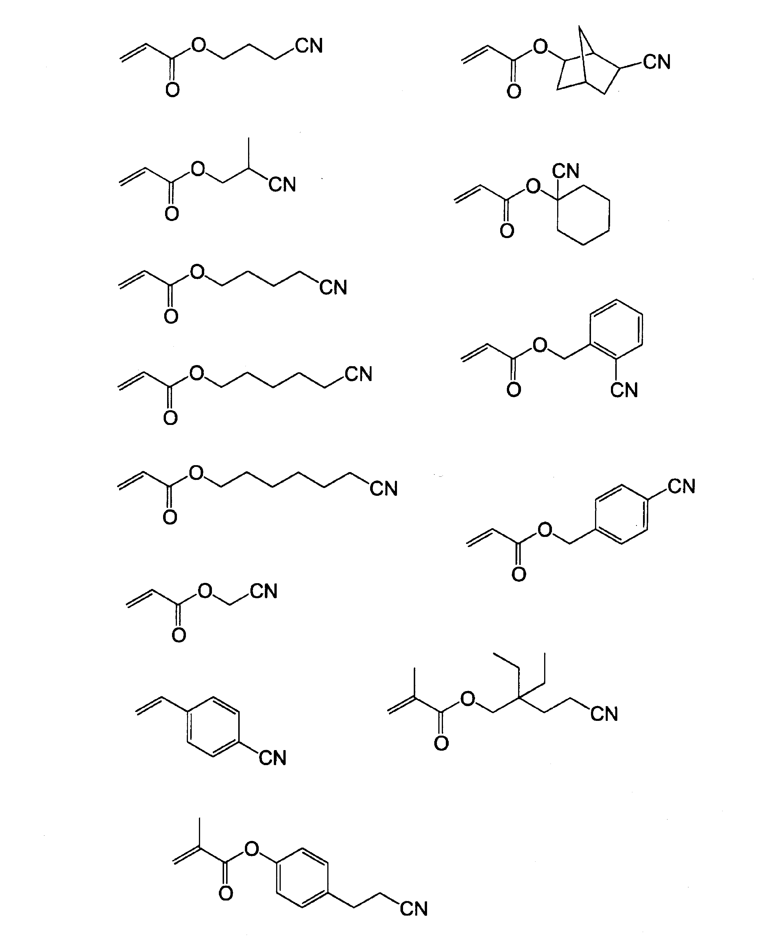
重合性基及び相互作用性基を有する化合物(マクロモノマー、オリゴマー、ポリマー等)において、相互作用性基を有するモノマーに由来するユニットは、めっき触媒又はその前駆体との相互作用形成性の観点から、重合性基及び相互作用性基を有する重合性化合物中に、40~95モル%の範囲で含有されることが好ましく、50~80モル%の範囲で含有されることがより好ましい。
また、重合性基及び相互作用性基を有するポリマーを得る際には、吸水性を低下させるため、また、疎水性を向上させるために、上記相互作用性基を有するモノマー以外に他のモノマーを用いてもよい。他のモノマーとしては、一般的な重合性モノマーを用いてよく、ジエン系モノマー、アクリル系モノマー等が挙げられる。中でも、無置換アルキルのアクリル系モノマーが好ましい。具体的には、ターシャリーブチルアクリレート、2-エチルヘキシルアクリレート、ブチルアクリレート、シクロヘキシルアクリレート、ベンジルメタクリレートなどが好ましく使用できる。
このような重合性基及び相互作用性基を有するポリマーは、以下のように合成できる。
合成方法としては、i)相互作用性基を有するモノマーと重合性基を有するモノマーとを共重合する方法、ii)相互作用性基を有するモノマーと二重結合前駆体を有するモノマーとを共重合させ、次に塩基などの処理により二重結合を導入する方法、iii)相互作用性基を有するポリマーと重合性基を有するモノマーとを反応させ、二重結合を導入(重合性基を導入する)方法が挙げられる。好ましいのは、合成適性の観点から、ii)相互作用性基を有するモノマーと二重結合前駆体を有するモノマーとを共重合させ、次に塩基などの処理により二重結合を導入する方法、iii)相互作用性基を有するポリマーと重合性基を有するモノマーとを反応させ、重合性基を導入する方法である。
合成方法としては、i)相互作用性基を有するモノマーと重合性基を有するモノマーとを共重合する方法、ii)相互作用性基を有するモノマーと二重結合前駆体を有するモノマーとを共重合させ、次に塩基などの処理により二重結合を導入する方法、iii)相互作用性基を有するポリマーと重合性基を有するモノマーとを反応させ、二重結合を導入(重合性基を導入する)方法が挙げられる。好ましいのは、合成適性の観点から、ii)相互作用性基を有するモノマーと二重結合前駆体を有するモノマーとを共重合させ、次に塩基などの処理により二重結合を導入する方法、iii)相互作用性基を有するポリマーと重合性基を有するモノマーとを反応させ、重合性基を導入する方法である。
重合性基及び相互作用性基を有するポリマーの合成に用いられる、相互作用性基を有するモノマーとしては、上記の相互作用性基を有するモノマーと同様のモノマーを用いることができる。モノマーは、一種単独で用いてもよいし、2種以上を併用してもよい。
相互作用性基を有するモノマーと共重合させる重合性基を有するモノマーとしては、アリル(メタ)アクリレート、2-アリルオキシエチルメタクリレートなどが挙げられる。
また、二重結合前駆体を有するモノマーとしては2-(3-クロロ-1-オキソプロポキシ)エチルメタクリレー卜、2-(3-ブロモ-1-オキソプロポキシ)エチルメタクリレート、などが挙げられる。
また、二重結合前駆体を有するモノマーとしては2-(3-クロロ-1-オキソプロポキシ)エチルメタクリレー卜、2-(3-ブロモ-1-オキソプロポキシ)エチルメタクリレート、などが挙げられる。
更に、相互作用性基を有するポリマー中の、カルボキシル基、アミノ基若しくはそれらの塩、水酸基、及びエポキシ基などの官能基との反応を利用して不飽和基を導入するために用いられる重合性基を有するモノマーとしては、(メタ)アクリル酸、グリシジル(メタ)アクリレート、アリルグリシジルエーテル、2-イソシアナトエチル(メタ)アクリレートなどがある。
以下、本発明において好適に用いられる重合性基及び相互作用性基を有するポリマーの具体例を示すが、本発明はこれに限定されるものではない。
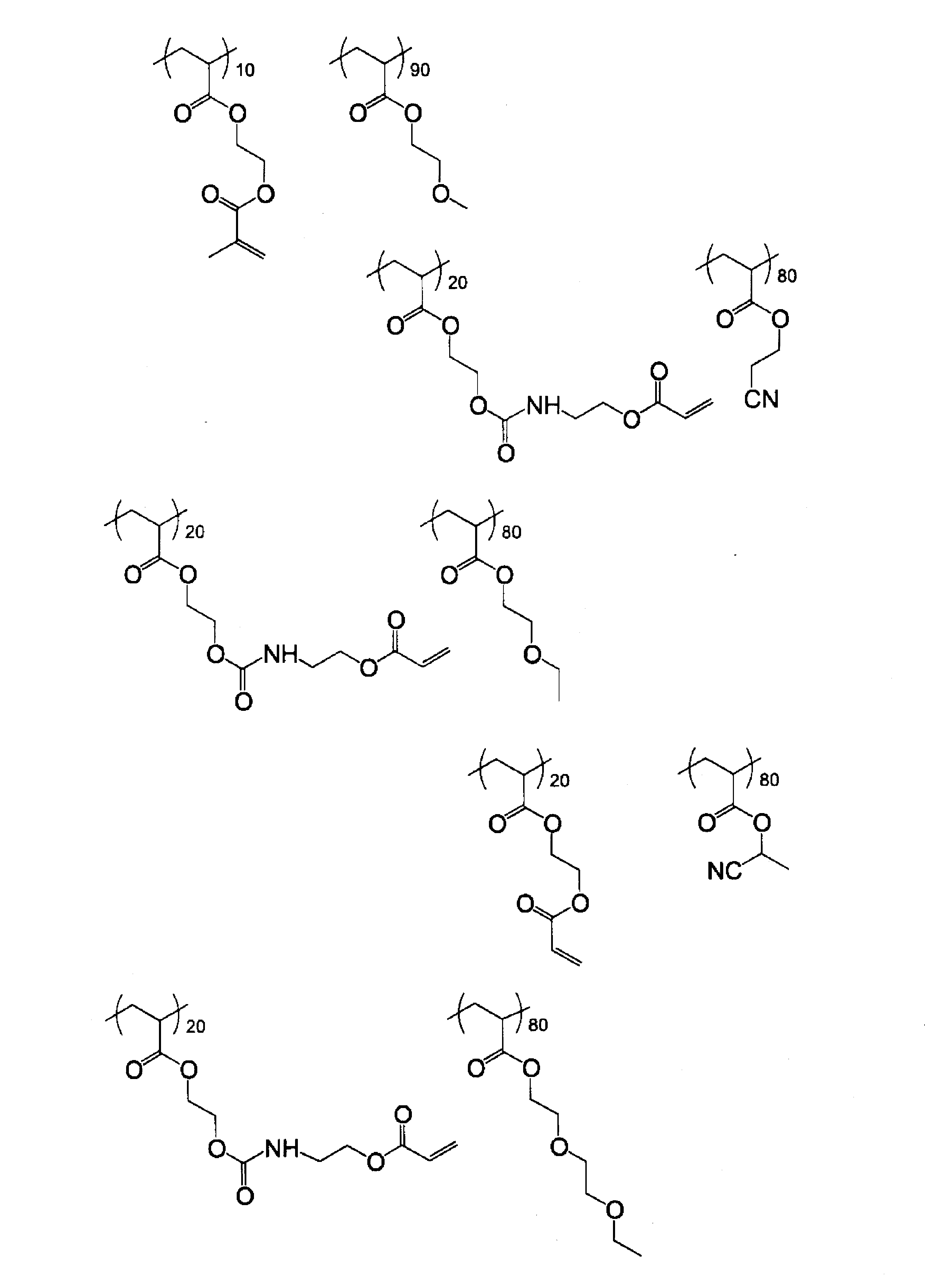
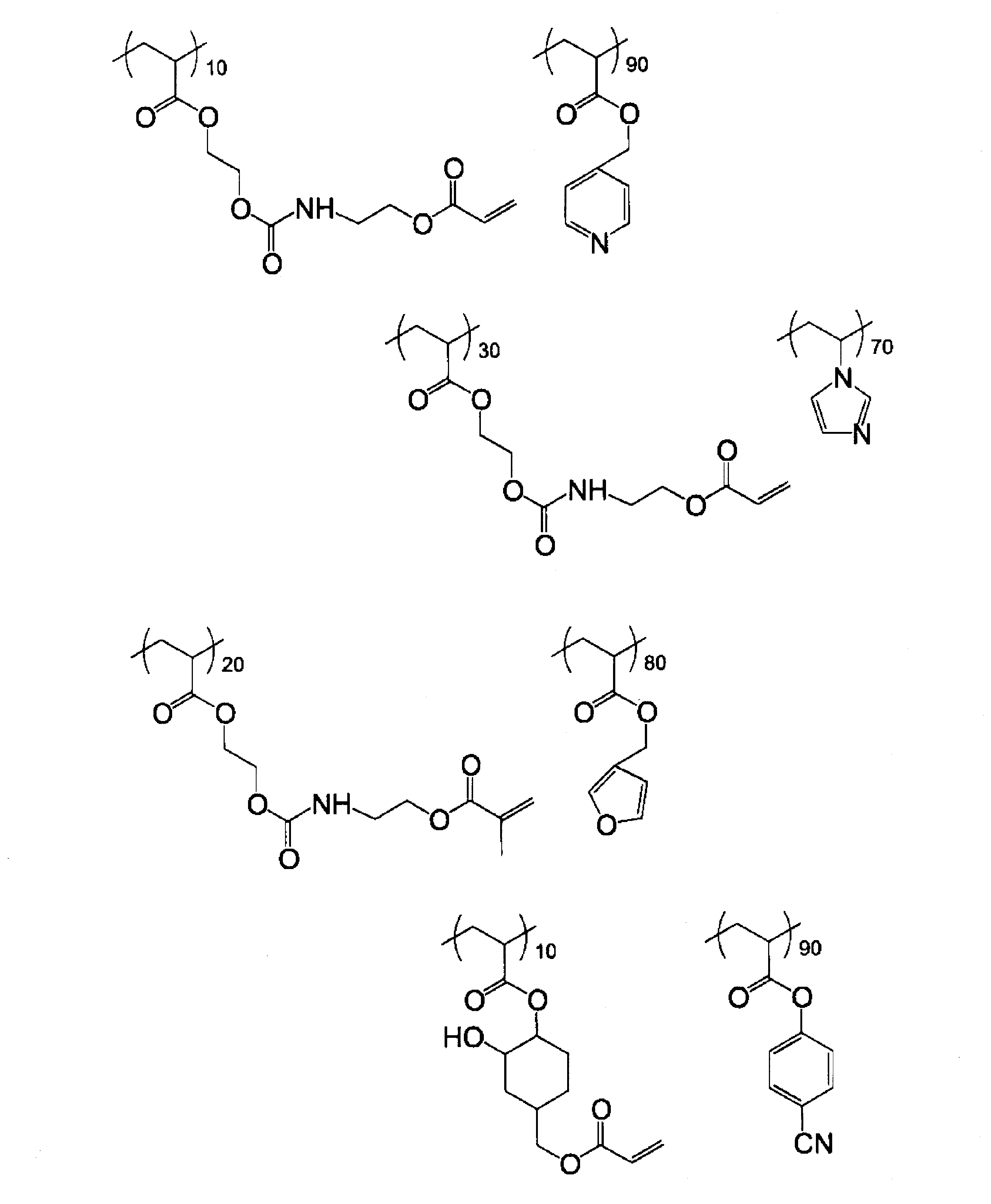
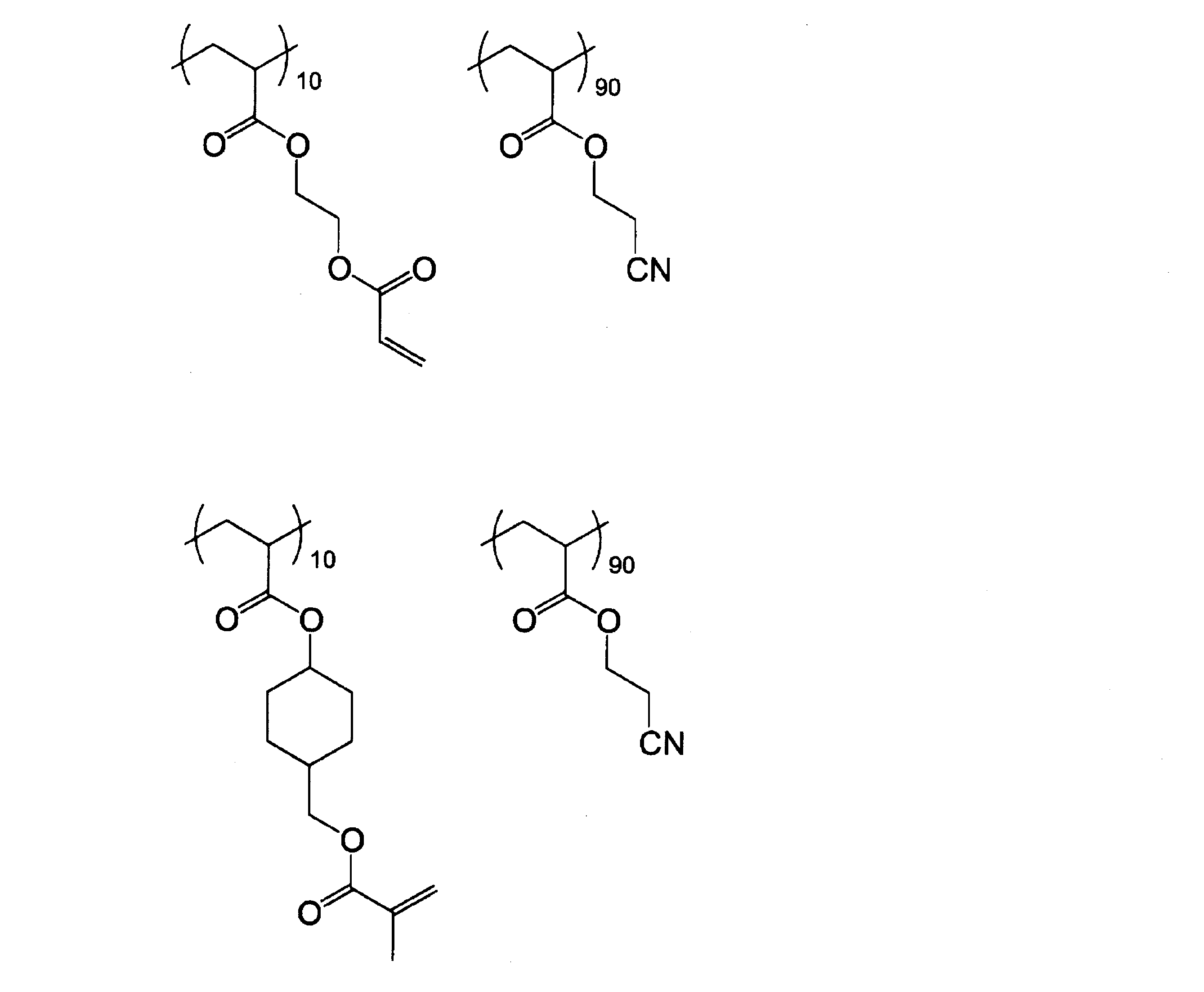
本発明において、重合性基及び相互作用性基を有するポリマーとしては、相互作用性基としてシアノ基を有するポリマー(以下、「シアノ基含有重合性ポリマー」と称する。)が好ましい。
本発明におけるシアノ基含有重合性ポリマーは、例えば、下記式(1)で表されるユニット、及び、下記式(2)で表されるユニットを含む共重合体であることが好ましい。
本発明におけるシアノ基含有重合性ポリマーは、例えば、下記式(1)で表されるユニット、及び、下記式(2)で表されるユニットを含む共重合体であることが好ましい。

上記式(1)及び式(2)中、R1~R5は、夫々独立して、水素原子、又は置換若しくは無置換のアルキル基を表し、X、Y及びZは、夫々独立して、単結合、置換若しく無置換の二価の有機基、エステル基、アミド基、又はエーテル基を表し、L1及びL2は、夫々独立して、置換若しくは無置換の二価の有機基を表す。
R1~R5が、置換若しくは無置換のアルキル基である場合、無置換のアルキル基としては、メチル基、エチル基、プロピル基、ブチル基が挙げられ、また、置換アルキル基としては、メトキシ基、ヒドロキシ基、塩素原子、臭素原子、フッ素原子等で置換された、メチル基、エチル基、プロピル基、ブチル基が挙げられる。
なお、R1としては、水素原子、メチル基、或いは、ヒドロキシ基又は臭素原子で置換されたメチル基が好ましい。
R2としては、水素原子、メチル基、或いは、ヒドロキシ基又は臭素原子で置換されたメチル基が好ましい。
R3としては、水素原子が好ましい。
R4としては、水素原子が好ましい。
R5としては、水素原子、メチル基、或いは、ヒドロキシ基又は臭素原子で置換されたメチル基が好ましい。
なお、R1としては、水素原子、メチル基、或いは、ヒドロキシ基又は臭素原子で置換されたメチル基が好ましい。
R2としては、水素原子、メチル基、或いは、ヒドロキシ基又は臭素原子で置換されたメチル基が好ましい。
R3としては、水素原子が好ましい。
R4としては、水素原子が好ましい。
R5としては、水素原子、メチル基、或いは、ヒドロキシ基又は臭素原子で置換されたメチル基が好ましい。
X、Y及びZが、置換若しくは無置換の二価の有機基の場合、該二価の有機基としては、置換若しくは無置換の脂肪族炭化水素基、置換若しくは無置換の芳香族炭化水素基が挙げられる。
置換若しくは無置換の脂肪族炭化水素基としては、メチレン基、エチレン基、プロピレン基、ブチレン基、又はこれらの基が、メトキシ基、ヒドロキシ基、塩素原子、臭素原子、フッ素原子等で置換されたものが好ましい。
置換若しくは無置換の芳香族炭化水素基としては、無置換のフェニル基、若しくは、メトキシ基、ヒドロキシ基、塩素原子、臭素原子、フッ素原子等で置換されたフェニル基が好ましい。
中でも、-(CH2)n-(nは1~3の整数)が好ましく、更に好ましくは-CH2-である。
置換若しくは無置換の脂肪族炭化水素基としては、メチレン基、エチレン基、プロピレン基、ブチレン基、又はこれらの基が、メトキシ基、ヒドロキシ基、塩素原子、臭素原子、フッ素原子等で置換されたものが好ましい。
置換若しくは無置換の芳香族炭化水素基としては、無置換のフェニル基、若しくは、メトキシ基、ヒドロキシ基、塩素原子、臭素原子、フッ素原子等で置換されたフェニル基が好ましい。
中でも、-(CH2)n-(nは1~3の整数)が好ましく、更に好ましくは-CH2-である。
L1は、ウレタン結合又はウレア結合を有する二価の有機基が好ましく、ウレタン結合を有する二価の有機基がより好ましく、中でも、総炭素数1~9であるものが好ましい。なお、ここで、L1の総炭素数とは、L1で表される置換若しくは無置換の二価の有機基に含まれる総炭素原子数を意味する。
L1の構造として、より具体的には、下記式(1-1)、又は、式(1-2)で表される構造であることが好ましい。
L1の構造として、より具体的には、下記式(1-1)、又は、式(1-2)で表される構造であることが好ましい。

上記式(1-1)及び式(1-2)中、Ra及びRbは、夫々独立して、炭素原子、水素原子、及び酸素原子からなる群より選択される2つ以上の原子を用いて形成される2価の有機基であり、好ましくは、置換若しくは無置換の、メチレン基、エチレン基、プロピレン基、又はブチレン基、エチレンオキシド基、ジエチレンオキシド基、トリエチレンオキシド基、テトラエチレンオキシド基、ジプロピレンオキシド基、トリプロピレンオキシド基、テトラプロピレンオキシド基が挙げられる。
また、L2は、直鎖、分岐、若しくは環状のアルキレン基、芳香族基、又はこれらを組み合わせた基であることが好ましい。該アルキレン基と芳香族基とを組み合わせた基は、更に、エーテル基、エステル基、アミド基、ウレタン基、ウレア基を介していてもよい。中でも、L2は総炭素数が1~15であることが好ましく、特に無置換であることが好ましい。なお、ここで、L2の総炭素数とは、L2で表される置換若しくは無置換の二価の有機基に含まれる総炭素原子数を意味する。
具体的には、メチレン基、エチレン基、プロピレン基、ブチレン基、フェニレン基、及びこれらの基が、メトキシ基、ヒドロキシ基、塩素原子、臭素原子、フッ素原子等で置換されたもの、更には、これらを組み合わせた基が挙げられる。
具体的には、メチレン基、エチレン基、プロピレン基、ブチレン基、フェニレン基、及びこれらの基が、メトキシ基、ヒドロキシ基、塩素原子、臭素原子、フッ素原子等で置換されたもの、更には、これらを組み合わせた基が挙げられる。
本発明におけるシアノ基含有重合性ポリマーとしては、前記式(1)で表されるユニットが、下記式(3)で表されるユニットであることが好ましい。

上記式(3)中、R1及びR2は、夫々独立して、水素原子、又は置換若しく無置換のアルキル基を表し、Zは、単結合、置換若しくは無置換の二価の有機基、エステル基、アミド基、又はエーテル基を表し、Wは、酸素原子、又はNR(Rは、水素原子、又はアルキル基を表し、好ましくは、水素原子、又は炭素数1~5の無置換のアルキル基である。)を表し、L1は、置換若しくは無置換の二価の有機基を表す。
式(3)におけるR1及びR2は、前記式(1)におけるR1及びR2と同義であり、好ましい例も同様である。
式(3)におけるZは、前記式(1)におけるZと同義であり、好ましい例も同様である。
また、式(3)におけるL1も、前記式(1)におけるL1と同義であり、好ましい例も同様である。
また、式(3)におけるL1も、前記式(1)におけるL1と同義であり、好ましい例も同様である。
本発明におけるシアノ基含有重合性ポリマーとしては、前記式(3)で表されるユニットが、下記式(4)で表されるユニットであることが好ましい。
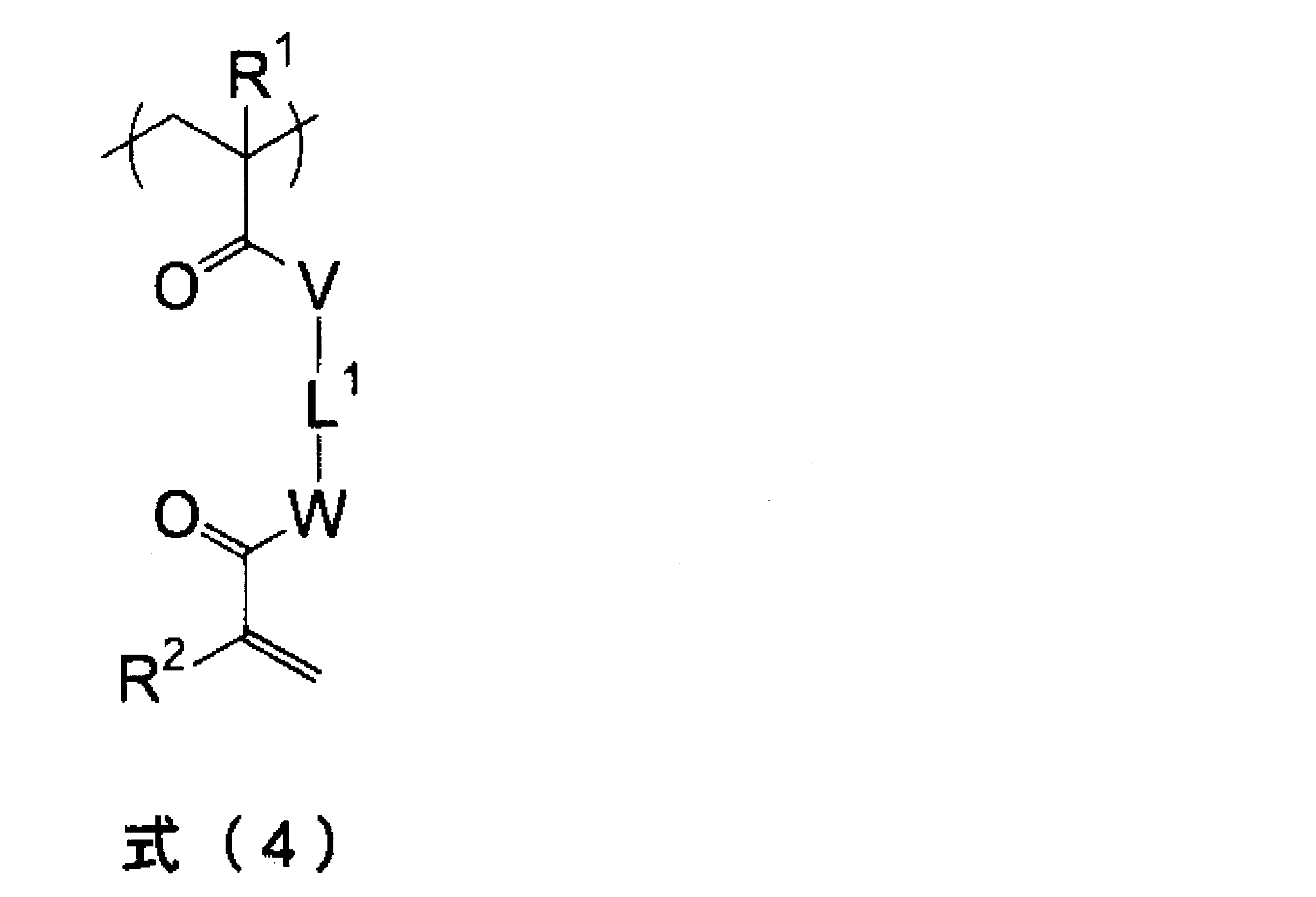
式(4)中、R1及びR2は、夫々独立して、水素原子、又は置換若しく無置換のアルキル基を表し、V及びWは、夫々独立して、酸素原子、又はNR(Rは、水素原子、又はアルキル基を表し、好ましくは、水素原子、又は炭素数1~5の無置換のアルキル基である。)を表し、L1は、置換若しくは無置換の二価の有機基を表す。
式(4)におけるR1及びR2は、前記式(1)におけるR1及びR2と同義であり、好ましい例も同様である。
式(4)におけるL1は、前記式(1)におけるL1と同義であり、好ましい例も同様である。
式(4)におけるL1は、前記式(1)におけるL1と同義であり、好ましい例も同様である。
前記式(3)及び式(4)において、Wは、酸素原子であることが好ましい。
また、前記式(3)及び式(4)において、L1は、無置換のアルキレン基、或いは、ウレタン結合又はウレア結合を有する二価の有機基が好ましく、ウレタン結合を有する二価の有機基がより好ましく、これら中でも、総炭素数1~9であるものが特に好ましい。
また、前記式(3)及び式(4)において、L1は、無置換のアルキレン基、或いは、ウレタン結合又はウレア結合を有する二価の有機基が好ましく、ウレタン結合を有する二価の有機基がより好ましく、これら中でも、総炭素数1~9であるものが特に好ましい。
また、本発明におけるシアノ基含有重合性ポリマーとしては、前記式(2)で表されるユニットが、下記式(5)で表されるユニットであることが好ましい。
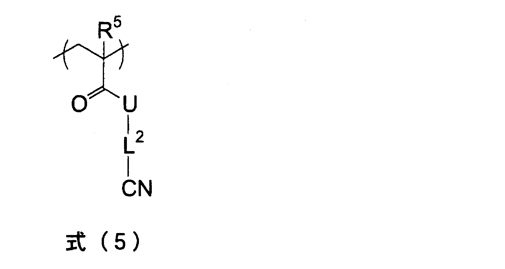
上記式(5)中、R5は、水素原子、又は置換若しく無置換のアルキル基を表し、Uは、酸素原子、又はNR’(R’は、水素原子、又はアルキル基を表し、好ましくは、水素原子、又は炭素数1~5の無置換のアルキル基である。)を表し、L2は、置換若しくは無置換の二価の有機基を表す。
式(5)におけるR5は、前記式(1)におけるR1及びR2と同義であり、水素原子であることが好ましい。
また、式(5)におけるL2は、前記式(1)におけるL2と同義であり、直鎖、分岐、若しくは環状のアルキレン基、芳香族基、又はこれらを組み合わせた基であることが好ましい。
特に、式(5)においては、L2中のシアノ基との連結部位が、直鎖、分岐、若しくは環状のアルキレン基を有する二価の有機基であることが好ましく、中でも、この二価の有機基が総炭素数1~10であることが好ましい。
また、別の好ましい態様としては、式(5)におけるL2中のシアノ基との連結部位が、芳香族基を有する二価の有機基であることが好ましく、中でも、該二価の有機基が、総炭素数6~15であることが好ましい。
特に、式(5)においては、L2中のシアノ基との連結部位が、直鎖、分岐、若しくは環状のアルキレン基を有する二価の有機基であることが好ましく、中でも、この二価の有機基が総炭素数1~10であることが好ましい。
また、別の好ましい態様としては、式(5)におけるL2中のシアノ基との連結部位が、芳香族基を有する二価の有機基であることが好ましく、中でも、該二価の有機基が、総炭素数6~15であることが好ましい。
本発明におけるシアノ基含有重合性ポリマーは、前記式(1)~式(5)で表されるユニットを含んで構成されるものであり、重合性基とシアノ基とを側鎖に有するポリマーである。
このシアノ基含有重合性ポリマーは、例えば、以下のように合成することができる。
このシアノ基含有重合性ポリマーは、例えば、以下のように合成することができる。
本発明におけるシアノ基含有重合性ポリマーを合成する際の重合反応の種類としては、ラジカル重合、カチオン重合、アニオン重合が挙げられる。反応制御の観点から、ラジカル重合、カチオン重合を用いることが好ましい。
本発明におけるシアノ基含有重合性ポリマーは、1)ポリマー主鎖を形成する重合形態と側鎖に導入される重合性基の重合形態とが異なる場合と、2)ポリマー主鎖を形成する重合形態と側鎖に導入される重合性基の重合形態とが同一の場合と、でその合成方法が異なる。
本発明におけるシアノ基含有重合性ポリマーは、1)ポリマー主鎖を形成する重合形態と側鎖に導入される重合性基の重合形態とが異なる場合と、2)ポリマー主鎖を形成する重合形態と側鎖に導入される重合性基の重合形態とが同一の場合と、でその合成方法が異なる。
1)ポリマー主鎖を形成する重合形態と側鎖に導入される重合性基の重合形態が異なる場合
ポリマー主鎖を形成する重合形態と側鎖に導入される重合性基の重合形態が異なる場合は、1-1)ポリマー主鎖形成がカチオン重合で行われ、側鎖に導入される重合性基の重合形態がラジカル重合である態様と、1-2)ポリマー主鎖形成がラジカル重合で行われ、側鎖に導入される重合性基の重合形態がカチオン重合である態様と、がある。
ポリマー主鎖を形成する重合形態と側鎖に導入される重合性基の重合形態が異なる場合は、1-1)ポリマー主鎖形成がカチオン重合で行われ、側鎖に導入される重合性基の重合形態がラジカル重合である態様と、1-2)ポリマー主鎖形成がラジカル重合で行われ、側鎖に導入される重合性基の重合形態がカチオン重合である態様と、がある。
1-1)ポリマー主鎖形成がカチオン重合で行われ、側鎖に導入される重合性基の重合形態がラジカル重合である態様
本発明において、ポリマー主鎖形成がカチオン重合で行われ、側鎖に導入される重合性基の重合形態がラジカル重合である態様で用いられるモノマーとしては、以下の化合物が挙げられる。
本発明において、ポリマー主鎖形成がカチオン重合で行われ、側鎖に導入される重合性基の重合形態がラジカル重合である態様で用いられるモノマーとしては、以下の化合物が挙げられる。
・重合性基含有ユニットを形成するために用いられるモノマー
本態様に用いられる重合性基含有ユニットを形成するために用いられるモノマーとしては、ビニル(メタ)アクリレート、アリル(メタ)アクリレート、4-(メタ)アクリロイルブタンビニルエーテル、2-(メタ)アクリロイルエタンビニルエーテル、3-(メタ)アクリロイルプロパンビニルエーテル、(メタ)アクリロイロキシジエチレングリコールビニルエーテル、(メタ)アクリロイロキシトリエチレングリコールビニルエーテル、(メタ)アクリロイル1stテルピオネール、1-(メタ)アクリロイロキシ-2-メチル-2-プロペン、1-(メタ)アクリロイロキシ-3-メチル-3-ブテン、3-メチレン-2-(メタ)アクリロイロキシ-ノルボルナン、4,4’-エチリデンジフェノールジ(メタ)アクリレート、メタクロレインジ(メタ)アクリロイルアセタール、p-((メタ)アクリロイルメチル)スチレン、アリル(メタ)アクリレート、2-(ブロモメチル)アクリル酸ビニル、2-(ヒドロキシメチル)アクリル酸アリル等が挙げられる。
本態様に用いられる重合性基含有ユニットを形成するために用いられるモノマーとしては、ビニル(メタ)アクリレート、アリル(メタ)アクリレート、4-(メタ)アクリロイルブタンビニルエーテル、2-(メタ)アクリロイルエタンビニルエーテル、3-(メタ)アクリロイルプロパンビニルエーテル、(メタ)アクリロイロキシジエチレングリコールビニルエーテル、(メタ)アクリロイロキシトリエチレングリコールビニルエーテル、(メタ)アクリロイル1stテルピオネール、1-(メタ)アクリロイロキシ-2-メチル-2-プロペン、1-(メタ)アクリロイロキシ-3-メチル-3-ブテン、3-メチレン-2-(メタ)アクリロイロキシ-ノルボルナン、4,4’-エチリデンジフェノールジ(メタ)アクリレート、メタクロレインジ(メタ)アクリロイルアセタール、p-((メタ)アクリロイルメチル)スチレン、アリル(メタ)アクリレート、2-(ブロモメチル)アクリル酸ビニル、2-(ヒドロキシメチル)アクリル酸アリル等が挙げられる。
・シアノ基含有ユニット形成するために用いられるモノマー
本態様に用いられるシアノ基含有ユニット形成するために用いられるモノマーとしては、2-シアノエチルビニルエーテル、シアノメチルビニルエーテル、3-シアノプロピルビニルエーテル、4-シアノブチルビニルエーテル、1-(p-シアノフェノキシ)-2-ビニロキシ-エタン、1-(o-シアノフェノキシ)-2-ビニロキシ-エタン、1-(m-シアノフェノキシ)-2-ビニロキシ-エタン、1-(p-シアノフェノキシ)-3-ビニロキシ-プロパン、1-(p-シアノフェノキシ)-4-ビニロキシ-ブタン、o-シアノベンジルビニルエーテル、m―シアノベンジルビニルエーテル、p―シアノベンジルビニルエーテル、アリルシアニド、アリルシアノ酢酸や、以下の化合物等が挙げられる。
本態様に用いられるシアノ基含有ユニット形成するために用いられるモノマーとしては、2-シアノエチルビニルエーテル、シアノメチルビニルエーテル、3-シアノプロピルビニルエーテル、4-シアノブチルビニルエーテル、1-(p-シアノフェノキシ)-2-ビニロキシ-エタン、1-(o-シアノフェノキシ)-2-ビニロキシ-エタン、1-(m-シアノフェノキシ)-2-ビニロキシ-エタン、1-(p-シアノフェノキシ)-3-ビニロキシ-プロパン、1-(p-シアノフェノキシ)-4-ビニロキシ-ブタン、o-シアノベンジルビニルエーテル、m―シアノベンジルビニルエーテル、p―シアノベンジルビニルエーテル、アリルシアニド、アリルシアノ酢酸や、以下の化合物等が挙げられる。
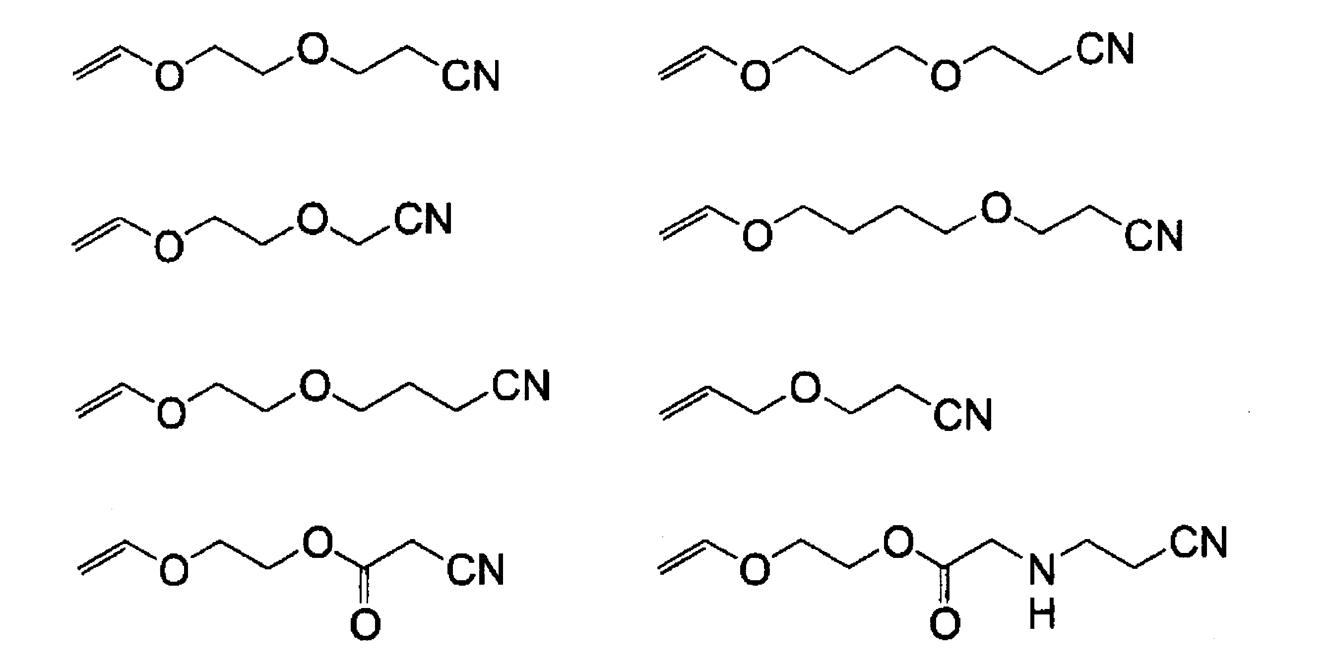
重合方法は、実験化学講座「高分子化学」2章-4(p74)に記載の方法や、「高分子合成の実験方法」大津隆行著 7章(p195)に記載の一般的なカチオン重合法が使用できる。なお、カチオン重合には、プロトン酸、ハロゲン化金属、有機金属化合物、有機塩、金属酸化物及び固体酸、ハロゲンが開始剤として用いることができるが、この中で、活性が大きく高分子量が合成可能な開始剤として、ハロゲン化金属と有機金属化合物の使用が好ましい。
具体的には、3フッ化ホウ素、3塩化ホウ素、塩化アルミ、臭化アルミ、四塩化チタン、四塩化スズ、臭化スズ、5フッ化リン、塩化アンチモン、塩化モリブデン、塩化タングステン、塩化鉄、ジクロロエチルアルミニウム、クロロジエチルアルミニウム、ジクロロメチルアルミニウム、クロロジメチルアルミニウム、トリメチルアルミニウム、トリメチル亜鉛、メチルグリニャールが挙げられる。
具体的には、3フッ化ホウ素、3塩化ホウ素、塩化アルミ、臭化アルミ、四塩化チタン、四塩化スズ、臭化スズ、5フッ化リン、塩化アンチモン、塩化モリブデン、塩化タングステン、塩化鉄、ジクロロエチルアルミニウム、クロロジエチルアルミニウム、ジクロロメチルアルミニウム、クロロジメチルアルミニウム、トリメチルアルミニウム、トリメチル亜鉛、メチルグリニャールが挙げられる。
1-2)ポリマー主鎖形成がラジカル重合で行われ、側鎖に導入される重合性基の重合形態がカチオン重合である態様
本発明において、ポリマー主鎖形成がラジカル重合で行われ、側鎖に導入される重合性基の重合形態がカチオン重合である態様用いられるモノマーとしては、以下の化合物が挙げられる。
本発明において、ポリマー主鎖形成がラジカル重合で行われ、側鎖に導入される重合性基の重合形態がカチオン重合である態様用いられるモノマーとしては、以下の化合物が挙げられる。
・重合性基含有ユニット形成するために用いられるモノマー
上記1-1)の態様で挙げた重合性基含有ユニット形成するために用いられるモノマーと同じものを用いることができる。
上記1-1)の態様で挙げた重合性基含有ユニット形成するために用いられるモノマーと同じものを用いることができる。
・シアノ基含有ユニット形成するために用いられるモノマー
本態様に用いられるシアノ基含有ユニット形成するために用いられるモノマーとしては、シアノメチル(メタ)アクリレート、2-シアノエチル(メタ)アクリレート、3-シアノプロピル(メタ)アクリレート、2-シアノプロピル(メタ)アクリレート、1-シアノエチル(メタ)アクリレート、4-シアノブチル(メタ)アクリレート、5-シアノペンチル(メタ)アクリレート、6-シアノヘキシル(メタ)アクリレート、7-シアノヘプチル(メタ)アクリレート、8-シアノオクチル(メタ)アクリレート、2-シアノエチル-(3-(ブロモメチル)アクリレート)、2-シアノエチル-(3-(ヒドロキシメチル)アクリルレート)、p-シアノフェニル(メタ)アクリレート、o-シアノフェニル(メタ)アクリレート、m-シアノフェニル(メタ)アクリレート、5-(メタ)アクリロイル-2-カルボニトリロ-ノルボルネン、6-(メタ)アクリロイル-2-カルボニトリロ-ノルボルネン、1-シアノ-1-(メタ)アクリロイル-シクロヘキサン、1,1-ジメチル-1-シアノ-メチル(メタ)アクリレート、1-メチル-1-エチル-1-シアノ-メチル(メタ)アクリレート、o-シアノベンジル(メタ)アクリレート、m-シアノベンジル(メタ)アクリレート、p-シアノベンジル(メタ)アクリレート、1―シアノシクロヘプチルアクリレート、2―シアノフェニルアクリレート、3―シアノフェニルアクリレート、シアノ酢酸ビニル、1―シアノ-1―シクロプロパンカルボン酸ビニル、シアノ酢酸アリル、1―シアノ-1―シクロプロパンカルボン酸アリル、N,N―ジシアノメチル(メタ)アクリルアミド、N-シアノフェニル(メタ)アクリルアミド、アリルシアノメチルエーテル、アリル-o―シアノエチルエーテル、アリル-m―シアノベンジルエーテル、アリル-p―シアノベンジルエーテルなどが挙げられる。
また、上記モノマーの水素の一部を、ヒドロキシル基、アルコキシ基、ハロゲン、シアノ基などで置換した構造を持つモノマーも使用可能である。
重合方法は、実験化学講座「高分子化学」2章-2(p34)に記載の方法や、「高分子合成の実験方法」大津隆行著 5章(p125)に記載の一般的なラジカル重合法が使用できる。なお、ラジカル重合の開始剤には、100℃以上の加熱が必要な高温開始剤、40~100℃の加熱で開始する通常開始剤、極低温で開始するレドックス開始剤などが知られているが、開始剤の安定性、重合反応のハンドリングのし易さから、通常開始剤が好ましい。
通常開始剤としては、過酸化ベンゾイル、過酸化ラウロイル、ペルオキソ2硫酸塩、アゾビスイソブチロニトリル、アゾビル-2,4-ジメチルバレロニトリルが挙げられる。
通常開始剤としては、過酸化ベンゾイル、過酸化ラウロイル、ペルオキソ2硫酸塩、アゾビスイソブチロニトリル、アゾビル-2,4-ジメチルバレロニトリルが挙げられる。
2)ポリマー主鎖を形成する重合形態と側鎖に導入される重合性基の重合形態とが同一の場合
ポリマー主鎖を形成する重合形態と側鎖に導入される重合性基の重合形態とが同一の場合は、2-1)両者がカチオン重合の態様と、2-2)両者がラジカル重合である態様と、がある。
ポリマー主鎖を形成する重合形態と側鎖に導入される重合性基の重合形態とが同一の場合は、2-1)両者がカチオン重合の態様と、2-2)両者がラジカル重合である態様と、がある。
2-1)両者がカチオン重合の態様
両者がカチオン重合の態様には、シアノ基を有するモノマーとして、前記1-1)の態様で挙げたシアノ基含有ユニット形成するために用いられるモノマーと同じものを用いることができる。
なお、重合中のゲル化を防止する観点から、シアノ基を有するポリマーを予め合成した後、該ポリマーと、カチオン重合性の重合性基を有する化合物(以下、適宜、「反応性化合物」と称する。)と、を反応させ、側鎖にカチオン重合性の重合性基を導入する方法を用いることが好ましい。
両者がカチオン重合の態様には、シアノ基を有するモノマーとして、前記1-1)の態様で挙げたシアノ基含有ユニット形成するために用いられるモノマーと同じものを用いることができる。
なお、重合中のゲル化を防止する観点から、シアノ基を有するポリマーを予め合成した後、該ポリマーと、カチオン重合性の重合性基を有する化合物(以下、適宜、「反応性化合物」と称する。)と、を反応させ、側鎖にカチオン重合性の重合性基を導入する方法を用いることが好ましい。
なお、シアノ基を有するポリマーは、反応性化合物との反応のために、下記に示すような反応性基を有することが好ましい。
また、シアノ基を有するポリマーと反応性化合物とは、以下のような官能基の組み合わせとなるように、適宜、選択されることが好ましい。
具体的な組み合わせとしては、(ポリマーの反応性基、反応性化合物の官能基)=(カルボキシル基、カルボキシル基)、(カルボキシル基、エポキシ基)、(カルボキシル基、イソシアネート基)、(カルボキシル基、ハロゲン化ベンジル)、(水酸基、カルボキシル基)、(水酸基、エポキシ基)、(水酸基、イソシアネート基)、(水酸基、ハロゲン化ベンジル)(イソシアネート基、水酸基)、(イソシアネート基、カルボキシル基)等を挙げることができる。
また、シアノ基を有するポリマーと反応性化合物とは、以下のような官能基の組み合わせとなるように、適宜、選択されることが好ましい。
具体的な組み合わせとしては、(ポリマーの反応性基、反応性化合物の官能基)=(カルボキシル基、カルボキシル基)、(カルボキシル基、エポキシ基)、(カルボキシル基、イソシアネート基)、(カルボキシル基、ハロゲン化ベンジル)、(水酸基、カルボキシル基)、(水酸基、エポキシ基)、(水酸基、イソシアネート基)、(水酸基、ハロゲン化ベンジル)(イソシアネート基、水酸基)、(イソシアネート基、カルボキシル基)等を挙げることができる。
ここで、反応性化合物として、具体的には、以下に示す化合物を用いることができる。
即ち、アリルアルコール、4-ヒドロキシブタンビニルエーテル、2-ヒドロキシエタンビニルエーテル、3-ヒドロキシプロパンビニルエーテル、ヒドロキシトリエチレングリコールビニルエーテル、1stテルピオネール、2-メチル-2-プロペノール、3-メチル-3-ブテノール、3-メチレン-2-ヒドロキシ-ノルボルナン、p-(クロロメチル)スチレンである。
即ち、アリルアルコール、4-ヒドロキシブタンビニルエーテル、2-ヒドロキシエタンビニルエーテル、3-ヒドロキシプロパンビニルエーテル、ヒドロキシトリエチレングリコールビニルエーテル、1stテルピオネール、2-メチル-2-プロペノール、3-メチル-3-ブテノール、3-メチレン-2-ヒドロキシ-ノルボルナン、p-(クロロメチル)スチレンである。
2-2)両者がラジカル重合である態様
両者がラジカル重合である態様では、合成方法としては、i)シアノ基を有するモノマーと重合性基を有するモノマーとを共重合する方法、ii)シアノ基を有するモノマーと二重結合前駆体を有するモノマーとを共重合させ、次に塩基などの処理により二重結合を導入する方法、iii)シアノ基を有するポリマーと重合性基を有するモノマーとを反応させ、二重結合を導入(重合性基を導入する)方法が挙げられる。好ましいのは、合成適性の観点から、ii)シアノ基を有するモノマーと二重結合前駆体を有するモノマーとを共重合させ、次に塩基などの処理により二重結合を導入する方法、iii)シアノ基を有するポリマーと重合性基を有するモノマーとを反応させ、重合性基を導入する方法である。
両者がラジカル重合である態様では、合成方法としては、i)シアノ基を有するモノマーと重合性基を有するモノマーとを共重合する方法、ii)シアノ基を有するモノマーと二重結合前駆体を有するモノマーとを共重合させ、次に塩基などの処理により二重結合を導入する方法、iii)シアノ基を有するポリマーと重合性基を有するモノマーとを反応させ、二重結合を導入(重合性基を導入する)方法が挙げられる。好ましいのは、合成適性の観点から、ii)シアノ基を有するモノマーと二重結合前駆体を有するモノマーとを共重合させ、次に塩基などの処理により二重結合を導入する方法、iii)シアノ基を有するポリマーと重合性基を有するモノマーとを反応させ、重合性基を導入する方法である。
前記i)の合成方法で用いられる重合性基を有するモノマーとしては、アリル(メタ)アクリレートや、以下の化合物などが挙げられる。
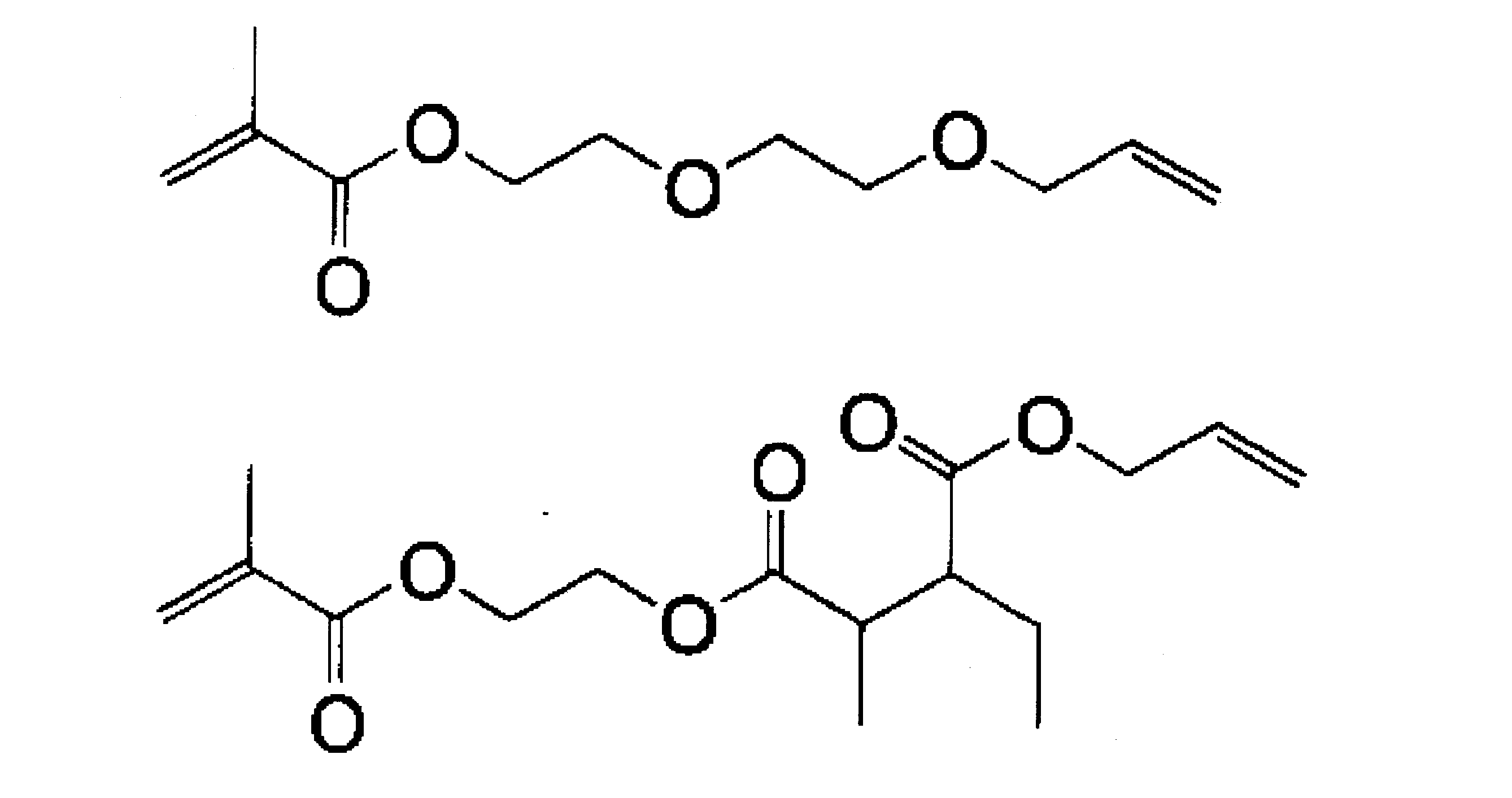
前記ii)の合成方法で用いられる二重結合前駆体を有するモノマーとしては、下記式(a)で表される化合物などが挙げられる。

上記式(a)中、Aは重合性基を有する有機団、R1~R3は、夫々独立して、水素原子又は1価の有機基、B及びCは脱離反応により除去される脱離基であり、ここでいう脱離反応とは、塩基の作用によりCが引き抜かれ、Bが脱離するものである。Bはアニオンとして、Cはカチオンとして脱離するものが好ましい。
式(a)で表される化合物としては、具体的には以下の化合物を挙げることができる。
式(a)で表される化合物としては、具体的には以下の化合物を挙げることができる。
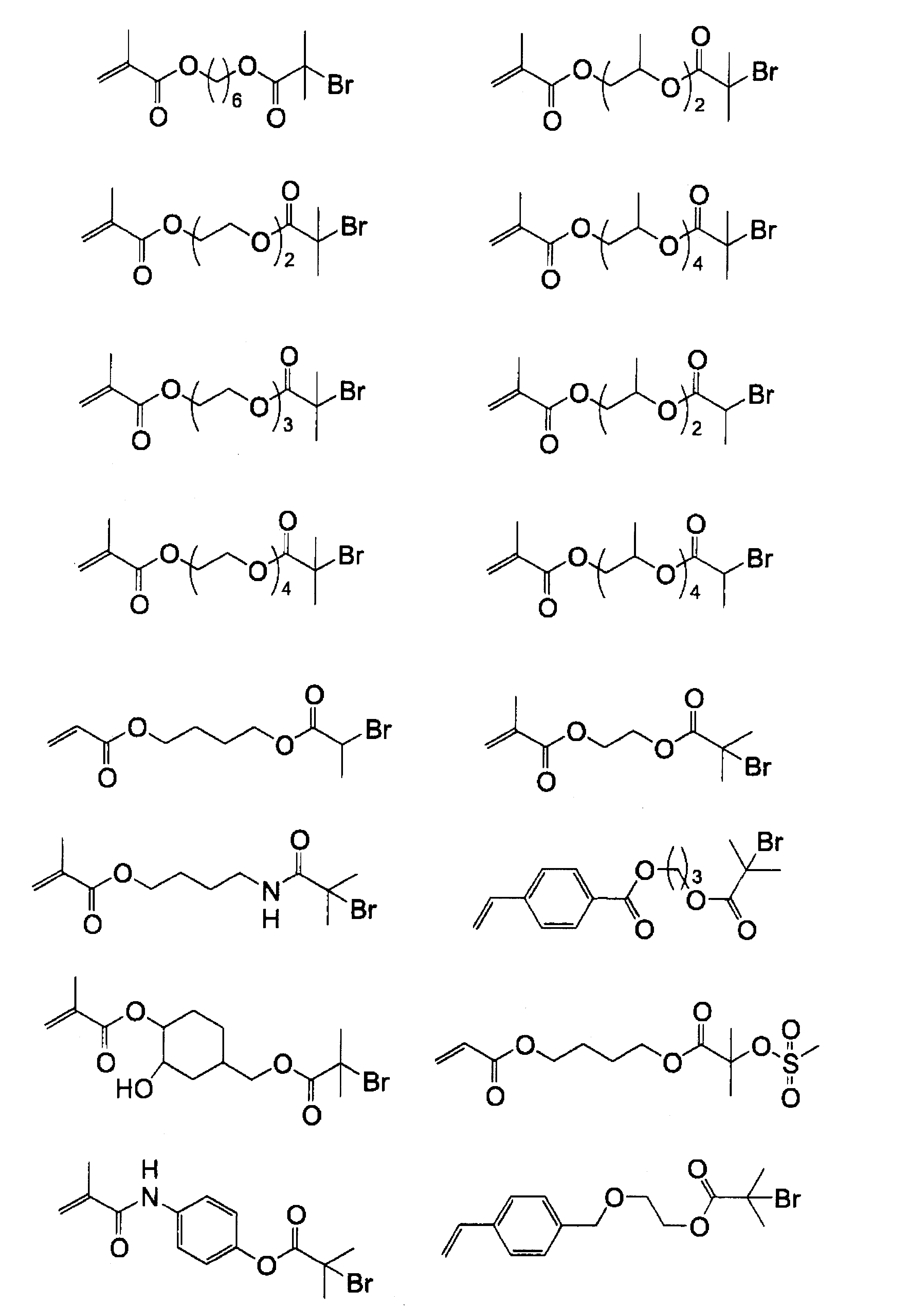

また、前記ii)の合成方法において、二重結合前駆体を二重結合に変換するには、下記に示すように、B、Cで表される脱離基を脱離反応により除去する方法、つまり、塩基の作用によりCを引き抜き、Bが脱離する反応を使用する。

上記の脱離反応において用いられる塩基としては、アルカリ金属類の水素化物、水酸化物又は炭酸塩、有機アミン化合物、金属アルコキシド化合物が好ましい例として挙げられる。アルカリ金属類の水素化物、水酸化物、又は炭酸塩の好ましい例としては、水素化ナトリウム、水素化カルシウム、水素化カリウム、水酸化ナトリウム、水酸化カリウム、水酸化カルシウム、炭酸カリウム、炭酸ナトリウム、炭酸水素カリウム、炭酸水素ナトリウムなどが挙げられる。有機アミン化合物の好ましい例としては、トリメチルアミン、トリエチルアミン、ジエチルメチルアミン、トリブチルアミン、トリイソブチルアミン、トリヘキシルアミン、トリオクチルアミン、N,N-ジメチルシクロヘキシルアミン、N,N-ジエチルシクロヘキシルアミン、N-メチルジシクロヘキシルアミン、N-エチルジシクロヘキシルアミン、ピロリジン、1-メチルピロリジン、2,5-ジメチルピロリジン、ピペリジン、1-メチルピペリジン、2,2,6,6-テトラメチルピペリジン、ピペラジン、1,4-ジメチルピペラジン、キヌクリジン、1,4-ジアザビシクロ[2,2,2]-オクタン、ヘキサメチレンテトラミン、モルホリン、4-メチルモルホリン、ピリジン、ピコリン、4-ジメチルアミノピリジン、ルチジン、1,8-ジアザビシクロ〔5,4,0〕-7-ウンデセン(DBU)、N,N’-ジシクロヘキシルカルボジイミド(DCC)、ジイソプロピルエチルアミン、Schiff塩基などが挙げられる。金属アルコキシド化合物の好ましい例としては、ナトリウムメトキシド、ナトリウムエトキシド、カリウムt-ブトキシドなどが挙げられる。これらの塩基は、1種或いは2種以上の混合であってもよい。
また、前記脱離反応において、塩基を付与(添加)する際に用いられる溶媒としては、例えば、エチレンジクロリド、シクロヘキサノン、メチルエチルケトン、アセトン、メタノール、エタノール、プロパノール、ブタノール、エチレングリコールモノメチルエーテル、エチレングリコールモノエチルエーテル、2-メトキシエチルアセテート、1-メトキシ-2-プロパノール、1-メトキシ-2-プロピルアセテート、N,N-ジメチルホルムアミド、N,N-ジメチルアセトアミド、ジメチルスルホキシド、トルエン、酢酸エチル、乳酸メチル、乳酸エチル、水などが挙げられる。これらの溶媒は単独或いは2種以上混合してもよい。
使用される塩基の量は、化合物中の特定官能基(B、Cで表される脱離基)の量に対して、当量以下であってもよく、また、当量以上であってもよい。また、過剰の塩基を使用した場合、脱離反応後、余剰の塩基を除去する目的で酸などを添加することも好ましい形態である。
前記iii)の合成方法において用いられるシアノ基を有するポリマーは、上記1-2)の態様で挙げたシアノ基含有ユニット形成するために用いられるモノマーと、二重結合導入のための反応性基を有するモノマーと、をラジカル重合することにより合成される。
二重結合導入のための反応性基を有するモノマーとしては、反応性基としてカルボキシル基、水酸基、エポキシ基、又はイソシアネート基を有するモノマーが挙げられる。
二重結合導入のための反応性基を有するモノマーとしては、反応性基としてカルボキシル基、水酸基、エポキシ基、又はイソシアネート基を有するモノマーが挙げられる。
カルボキシル基含有のモノマーとしては、(メタ)アクリル酸、イタコン酸、安息香酸ビニル、東亞合成製のアロニクスM-5300、M-5400、M-5600、三菱レーション製のアクリルエステルPA、HH、共栄社化学製のライトアクリレート HOA-HH、中村化学製のNKエステルSA、A-SAなどが挙げられる。
水酸基含有のモノマーとしては、2-ヒドロキシエチル(メタ)アクリレート、4-ヒドロキシブチル(メタ)アクリレート、2-ヒドロキシプロピル(メタ)アクリレート、2-ヒドロキシブチル(メタ)アクリレート、1-(メタ)アクリロイル-3-ヒドロキシ-アダマンタン、ヒドロキシメチル(メタ)アクリルアミド、(2-ヒドロキシエチル)-(メタ)アクリレート、3-クロロ-2-ヒドロキシプロピル(メタ)アクリレート、3,5-ジヒドロキシペンチル(メタ)アクリレート、1-ヒドロキシメチル-4-(メタ)アクリロイルメチル-シクロヘキサン、2-ヒドロキシ-3-フェノキシプロピル(メタ)アクリレート、1-メチル-2-アクリロイロキシプロピルフタル酸、2-アクリロイロキシエチル-2-ヒドロキシエチルフタル酸、1-メチル-2-アクリロイロキシエチル-2-ヒドロキシプロピルフタル酸、2-アクリロイロキシエチル-2-ヒドロキシ-3-クロロプロピルフタル酸、東亞合成(株)製のアロニクスM-554、M-154、M-555、M-155、M-158、日本油脂(株)製のブレンマーPE-200、PE-350、PP-500、PP-800、PP-1000、70PEP-350B、55PET800、以下の構造を有するラクトン変性アクリレートが使用できる。
CH2=CRCOOCH2CH2[OC(=O)C5H10]nOH
(R=H又はMe、n=1~5)
エポキシ基を有するモノマーとしては、グリシジル(メタ)アクリレート、ダイセル化学製のサイクロマーA、Mなどが使用できる。
イソシアネート基を有するモノマーとしては、昭和電工製のカレンズAOI、MOIが使用できる。
なお、iii)の合成方法において用いられるシアノ基を有するポリマーは、更に第3の共重合成分を含んでいてもよい。
イソシアネート基を有するモノマーとしては、昭和電工製のカレンズAOI、MOIが使用できる。
なお、iii)の合成方法において用いられるシアノ基を有するポリマーは、更に第3の共重合成分を含んでいてもよい。
前記iii)の合成方法において、シアノ基を有するポリマーと反応させる重合性基を有するモノマーとしては、シアノ基を有するポリマー中の反応性基の種類によって異なるが、以下の組合せの官能基を有するモノマーを使用することができる。
即ち、(ポリマーの反応性基、モノマーの官能基)=(カルボキシル基、カルボキシル基)、(カルボキシル基、エポキシ基)、(カルボキシル基、イソシアネート基)、(カルボキシル基、ハロゲン化ベンジル)、(水酸基、カルボキシル基)、(水酸基、エポキシ基)、(水酸基、イソシアネート基)、(水酸基、ハロゲン化ベンジル)(イソシアネート基、水酸基)、(イソシアネート基、カルボキシル基)、(エポキシ基、カルボキシル基)等を挙げることができる。
具体的には以下のモノマーを使用することができる。
即ち、(ポリマーの反応性基、モノマーの官能基)=(カルボキシル基、カルボキシル基)、(カルボキシル基、エポキシ基)、(カルボキシル基、イソシアネート基)、(カルボキシル基、ハロゲン化ベンジル)、(水酸基、カルボキシル基)、(水酸基、エポキシ基)、(水酸基、イソシアネート基)、(水酸基、ハロゲン化ベンジル)(イソシアネート基、水酸基)、(イソシアネート基、カルボキシル基)、(エポキシ基、カルボキシル基)等を挙げることができる。
具体的には以下のモノマーを使用することができる。

本発明におけるシアノ基含有重合性ポリマーにおいて、前記式(1)、式(3)、又は式(4)におけるL1がウレタン結合を有する二価の有機基である構造の場合には、下記の合成方法(以下、合成方法Aと称する。)で合成することが好ましい。
即ち、本発明における合成方法Aは、少なくとも溶媒中で、側鎖にヒドロキシル基を有するポリマー、及び、イソシアネート基と重合性基とを有する化合物を用い、該ヒドロキシル基に該イソシアネート基を付加させることによりL1中のウレタン結合を形成することを特徴とする。
即ち、本発明における合成方法Aは、少なくとも溶媒中で、側鎖にヒドロキシル基を有するポリマー、及び、イソシアネート基と重合性基とを有する化合物を用い、該ヒドロキシル基に該イソシアネート基を付加させることによりL1中のウレタン結合を形成することを特徴とする。
ここで、合成方法Aに用いられる側鎖にヒドロキシル基を有するポリマーとしては、上記1-2)の態様で挙げたシアノ基含有ユニットを形成するために用いられるモノマーと、以下に示す挙げるヒドロキシル基含有(メタ)アクリレートと、の共重合体が好ましい。 ヒドロキシル基含有(メタ)アクリレートとしては、前記水酸基含有のモノマーとして例示した(メタ)アクリレートを挙げることができる。
なお、合成方法Aに用いられる側鎖にヒドロキシル基を有するポリマーは、更に第3の共重合成分を含んでいてもよい。
なお、合成方法Aに用いられる側鎖にヒドロキシル基を有するポリマーは、更に第3の共重合成分を含んでいてもよい。
上述のような側鎖にヒドロキシル基を有するポリマーの中でも、高分子量のポリマーを合成する観点から、原料として、ヒドロキシ基含有(メタ)アクリレートを合成する際に副生する2官能アクリレートを除去した原料を用いて合成したポリマーを使用することもできる。ヒドロキシ基含有(メタ)アクリレートの精製方法としては、蒸留、カラム精製が好ましい。更に好ましくは、下記(I)~(IV)の工程を順次経ることで得られたヒドロキシル基含有(メタ)アクリレートを用いて合成されたものであることが好ましい。
(I)ヒドロキシル基含有(メタ)アクリレートと、該ヒドロキシル基含有(メタ)アクリレートを合成する際に副生する2官能アクリレートと、を含む混合物を、水に溶解する工程
(II)得られた水溶液に、水と分離する第1の有機溶剤を加えた後、該第1の有機溶剤と前記2官能アクリレートとを含む層を水層から分離する工程
(III)前記水層に、前記ヒドロキシル基含有(メタ)アクリレートよりも水溶解性の高い化合物を溶解する工程
(IV)前記水層に第2の有機溶剤を加えて、前記ヒドロキシル基含有(メタ)アクリレートを抽出した後、濃縮する工程
(I)ヒドロキシル基含有(メタ)アクリレートと、該ヒドロキシル基含有(メタ)アクリレートを合成する際に副生する2官能アクリレートと、を含む混合物を、水に溶解する工程
(II)得られた水溶液に、水と分離する第1の有機溶剤を加えた後、該第1の有機溶剤と前記2官能アクリレートとを含む層を水層から分離する工程
(III)前記水層に、前記ヒドロキシル基含有(メタ)アクリレートよりも水溶解性の高い化合物を溶解する工程
(IV)前記水層に第2の有機溶剤を加えて、前記ヒドロキシル基含有(メタ)アクリレートを抽出した後、濃縮する工程
前記(I)の工程において用いられる混合物は、ヒドロキシル基含有(メタ)アクリレートと、該ヒドロキシル基含有(メタ)アクリレートを合成する際に副生する不純物である2官能アクリレートと、を含んでおり、ヒドロキシル基含有(メタ)アクリレートの一般的な市販品に相当する。
前記(I)の工程では、この市販品(混合物)を水に溶解して、水溶液を得る。
前記(I)の工程では、この市販品(混合物)を水に溶解して、水溶液を得る。
前記(II)の工程では、(I)の工程で得られた水溶液に対し、水と分離する第1の有機溶剤を加える。ここで用いられる、第1の有機溶剤としては、酢酸エチル、ジエチルエーテル、ベンゼン、トルエン等が挙げられる。
その後、水溶液(水層)から、この第1の有機溶剤と2官能アクリレートとを含む層(油層)を分離する。
その後、水溶液(水層)から、この第1の有機溶剤と2官能アクリレートとを含む層(油層)を分離する。
前記(III)の工程では、(II)の工程で油層と分離された水層に、ヒドロキシル基含有(メタ)アクリレートよりも水溶解性の高い化合物を溶解する。
ここで用いられるヒドロキシル基含有(メタ)アクリレートよりも水溶解性の高い化合物としては、塩化ナトリウム、塩化カリウムなどのアルカリ金属塩、硫酸マグネシウム、硫酸カルシウムなどのアルカリ土類金属塩などの無機塩等が用いられる。
ここで用いられるヒドロキシル基含有(メタ)アクリレートよりも水溶解性の高い化合物としては、塩化ナトリウム、塩化カリウムなどのアルカリ金属塩、硫酸マグネシウム、硫酸カルシウムなどのアルカリ土類金属塩などの無機塩等が用いられる。
前記(IV)の工程では、水層に第2の有機溶剤を加えて、ヒドロキシル基含有(メタ)アクリレートを抽出した後、濃縮する。
ここで用いられる第2の有機溶剤としては、酢酸エチル、ジエチルエーテル、ベンゼン、トルエン等が挙げられる。この第2の有機溶剤は、前述の第1の有機溶剤と同じであってもよいし、異なっていてもよい。
(IV)の工程における濃縮には、無水硫酸マグネシウムによる乾燥や、減圧留去等が用いられる。
ここで用いられる第2の有機溶剤としては、酢酸エチル、ジエチルエーテル、ベンゼン、トルエン等が挙げられる。この第2の有機溶剤は、前述の第1の有機溶剤と同じであってもよいし、異なっていてもよい。
(IV)の工程における濃縮には、無水硫酸マグネシウムによる乾燥や、減圧留去等が用いられる。
前記(I)~(IV)の工程を順次経ることで得られたヒドロキシル基含有(メタ)アクリレートを含む単離物は、その全質量中に2官能アクリレートを0.1質量%以下の範囲で含むことが好ましい。つまり、前記(I)~(IV)の工程を経ることで、混合物から不純物である2官能アクリレートが除去され、ヒドロキシル基含有(メタ)アクリレートが精製される。
2官能アクリレートの含有量のより好ましい範囲は、単離物の全質量中に0.05質量%以下であり、少なければ少ないほどよい。
このように精製されたヒドロキシル基含有(メタ)アクリレートを用いることで、不純物である2官能アクリレートが重合反応に影響を及ぼし難くなるため、重量平均分子量が20000以上のニトリル基含有重合性ポリマーを合成することができる。
2官能アクリレートの含有量のより好ましい範囲は、単離物の全質量中に0.05質量%以下であり、少なければ少ないほどよい。
このように精製されたヒドロキシル基含有(メタ)アクリレートを用いることで、不純物である2官能アクリレートが重合反応に影響を及ぼし難くなるため、重量平均分子量が20000以上のニトリル基含有重合性ポリマーを合成することができる。
前記(I)の工程において用いられるヒドロキシ基含有(メタ)アクリレートとしては、前述の合成方法Aに用いられる側鎖にヒドロキシル基を有するポリマーを合成する際に用いられるヒドロキシル基含有(メタ)アクリレートとして挙げられたものを用いることができる。中でも、イソシアネートへの反応性の観点から、第1級水酸基を有するモノマーが好ましく、更には、ポリマーの単位重量当たりの重合性基比率を高める観点から、分子量が100~250のヒドロキシ基含有(メタ)アクリレートが好ましい。
また、合成方法Aに用いられるイソシアネート基と重合性基とを有する化合物としては、2-アクリロイルオキシエチルイソシアネート(カレンズAOI、昭和電工(株)製)、2-メタクリルオキシイソシアネート(カレンズMOI、昭和電工(株)製)等が挙げられる。
また、合成方法Aに用いられる溶媒としては、SP値(沖津法により算出)が20~23MPa1/2であるものが好ましく、具体的には、エチレングリコールジアセテート、ジエチレングリコールジアセテート、プロピレングリコールジアセテート、アセト酢酸メチル、アセト酢酸エチル、1,2,3-トリアセトキシ-プロパン、シクロヘキサノン、2-(1-シクロヘキセニル)シクロヘキサノン、プロピオニトリル、N-メチルピロリドン、ジメチルアセトアミド、アセチルアセトン、アセトフェノン、トリアセチン、1,4-ジオキサン、ジメチルカーボネート等が挙げられる。
中でも、高分子量体を合成する観点から、エステル系溶媒であることがより好ましく、特に、エチレングリコールジアセテート、ジエチレングリコールジアセテート等のジアセテート系溶媒や、ジメチルカーボネートが更に好ましい。
ここで、本発明における溶媒のSP値は、沖津法(沖津俊直著「日本接着学会誌」29(3)(1993))によって算出したものである。具体的には、SP値は以下の式で計算されるものである。なお、ΔFは文献記載の値である。
SP値(δ)=ΣΔF(Molar Attraction Constants)/V(モル容積)
中でも、高分子量体を合成する観点から、エステル系溶媒であることがより好ましく、特に、エチレングリコールジアセテート、ジエチレングリコールジアセテート等のジアセテート系溶媒や、ジメチルカーボネートが更に好ましい。
ここで、本発明における溶媒のSP値は、沖津法(沖津俊直著「日本接着学会誌」29(3)(1993))によって算出したものである。具体的には、SP値は以下の式で計算されるものである。なお、ΔFは文献記載の値である。
SP値(δ)=ΣΔF(Molar Attraction Constants)/V(モル容積)
以上のようにして合成された本発明におけるシアノ基含有重合性ポリマーは、共重合成分全体に対し、重合性基含有ユニット、シアノ基含有ユニットの割合が以下の範囲であることが好ましい。
即ち、重合性基含有ユニットが、共重合成分全体に対し5~50mol%で含まれることが好ましく、更に好ましくは5~40mol%である。5mol%未満では反応性(硬化性、重合性)が落ち、50mol%より大きいと合成の際にゲル化しやすく合成しにくい。
また、シアノ基含有ユニットは、めっき触媒に対する吸着性の観点から、共重合成分全体に対し5~95mol%で含まれることが好ましく、更に好ましくは10~95mol%である。
即ち、重合性基含有ユニットが、共重合成分全体に対し5~50mol%で含まれることが好ましく、更に好ましくは5~40mol%である。5mol%未満では反応性(硬化性、重合性)が落ち、50mol%より大きいと合成の際にゲル化しやすく合成しにくい。
また、シアノ基含有ユニットは、めっき触媒に対する吸着性の観点から、共重合成分全体に対し5~95mol%で含まれることが好ましく、更に好ましくは10~95mol%である。
なお、本発明におけるシアノ基含有重合性ポリマーは、シアノ基含有ユニット、重合性基含有ユニット以外に、他のユニットを含んでいてもよい。この他のユニットを形成するために用いられるモノマーとしては、本発明の効果を損なわないものであれば、いかなるモノマーも使用することができる。
他のユニットを形成するために用いられるモノマーとしては、具体的には、アクリル樹脂骨格、スチレン樹脂骨格、フェノール樹脂(フェノール-ホルムアルデヒド樹脂)骨格、メラミン樹脂(メラミンとホルムアルデヒドの重縮合体)骨格、ユリア樹脂(尿素とホルムアルデヒドの重縮合体)骨格、ポリエステル樹脂骨格、ポリウレタン骨格、ポリイミド骨格、ポリオレフィン骨格、ポリシクロオレフィン骨格、ポリスチレン骨格、ポリアクリル骨格、ABS樹脂(アクリロニトリル、ブタジエン、スチレンの重合体)骨格、ポリアミド骨格、ポリアセタール骨格、ポリカーボネート骨格、ポリフェニレンエーテル骨格、ポリフェニレンスルファイド骨格、ポリスルホン骨格、ポリエーテルスルホン骨格、ポリアリール骨格、ポリエーテルエーテルケトン骨格、ポリアミドイミド骨格などの主鎖骨格を形成しうるモノマーが挙げられる。
また、これらの主鎖骨格は、シアノ基含有ユニットや、重合性基含有ユニットの主鎖骨格であってもよい。
ただし、前述のように重合性基をポリマーに反応させて導入する場合は、100%導入することが困難な際には少量の反応性部分が残ってしまうことから、これが第3のユニットとなる可能性もある。
具体的には、ラジカル重合でポリマー主鎖を形成する場合は、エチル(メタ)アクリレート、ブチル(メタ)アクリレート、ヘキシル(メタ)アクリレート、2-エチルヘキシル(メタ)アクリレート、シクロヘキシル(メタ)アクリレート、ベンジル(メタ)アクリレート、ステアリル(メタ)アクリレートなどの無置換(メタ)アクリル酸エステル類、2,2,2-トリフルオロエチル(メタ)アクリレート、3,3,3-トリフルオロプロピル(メタ)アクリレート、2-クロロエチル(メタ)アクリレートなどのハロゲン置換(メタ)アクリル酸エステル類、2-(メタ)アクリロイロキシエチルトリメチルアンモニウムクロライドなどのアンモニウム基置換(メタ)アクリル酸エステル類、ブチル(メタ)アクリルアミド、イソプロピル(メタ)アクリルアミド、オクチル(メタ)アクリルアミド、ジメチル(メタ)アクリルアミドなどの(メタ)アクリルアミド類、スチレン、ビニル安息香酸、p-ビニルベンジルアンモニウムクロライドなどのスチレン類、N-ビニルカルバゾール、酢酸ビニル、N-ビニルアセトアミド、N-ビニルカプロラクタムなどのビニル化合物類や、その他にジメチルアミノエチル(メタ)アクリレート、ジエチルアミノエチル(メタ)アクリレート、2-エチルチオ-エチル(メタ)アクリレート、(メタ)アクリル酸、2-ヒドロキシエチル(メタ)アクリレートなどが使用できる。
また、上記記載のモノマーを用いて得られたマクロモノマーも使用できる。
カチオン重合でポリマー主鎖を形成する場合は、エチルビニルエーテル、ブチルビニルエーテル、イソブチルビニルエーテル、シクロヘキシルビニルエーテル、エチレングリコールビニルエーテル、ジ(エチレングリコール)ビニルエーテル、1,4-ブタンジオールビニルエーテル、2-クロロエチルビニルエーテル、2-エチルヘキシルビニルエーテル、酢酸ビニル、2-ビニルオキシテトラヒドロピラン、ビニルベンゾエート、ビニルブチレートなどのビニルエーテル類、スチレン、p-クロロスチレン、p-メトキシスチレンなどのスチレン類、アリルアルコール、4-ヒドロキシ-1-ブテンなどの末端エチレン類を使用することができる。
本発明におけるシアノ基含有重合性ポリマーの重量平均分子量は、1000以上70万以下が好ましく、更に好ましくは2000以上20万以下である。特に、重合感度の観点から、本発明におけるシアノ基含有重合性ポリマーの重量平均分子量は、20000以上であることが好ましい。
また、本発明におけるシアノ基含有重合性ポリマーの重合度としては、10量体以上のものを使用することが好ましく、更に好ましくは20量体以上のものである。また、7000量体以下が好ましく、3000量体以下がより好ましく、2000量体以下が更に好ましく、1000量体以下が特に好ましい。
ここに記載されている分子量及び重合度の好ましい範囲は、本発明において用いられるシアノ基含有重合性ポリマー以外の重合性基及び相互作用性基を有するポリマーに関しても好適な範囲である。
また、本発明におけるシアノ基含有重合性ポリマーの重合度としては、10量体以上のものを使用することが好ましく、更に好ましくは20量体以上のものである。また、7000量体以下が好ましく、3000量体以下がより好ましく、2000量体以下が更に好ましく、1000量体以下が特に好ましい。
ここに記載されている分子量及び重合度の好ましい範囲は、本発明において用いられるシアノ基含有重合性ポリマー以外の重合性基及び相互作用性基を有するポリマーに関しても好適な範囲である。
本発明におけるシアノ基含有重合性ポリマーの具体例を以下に示すが、これらに限定されるものではない。
なお、これらの具体例の重量平均分子量は、いずれも、3000~100000の範囲である。
なお、これらの具体例の重量平均分子量は、いずれも、3000~100000の範囲である。

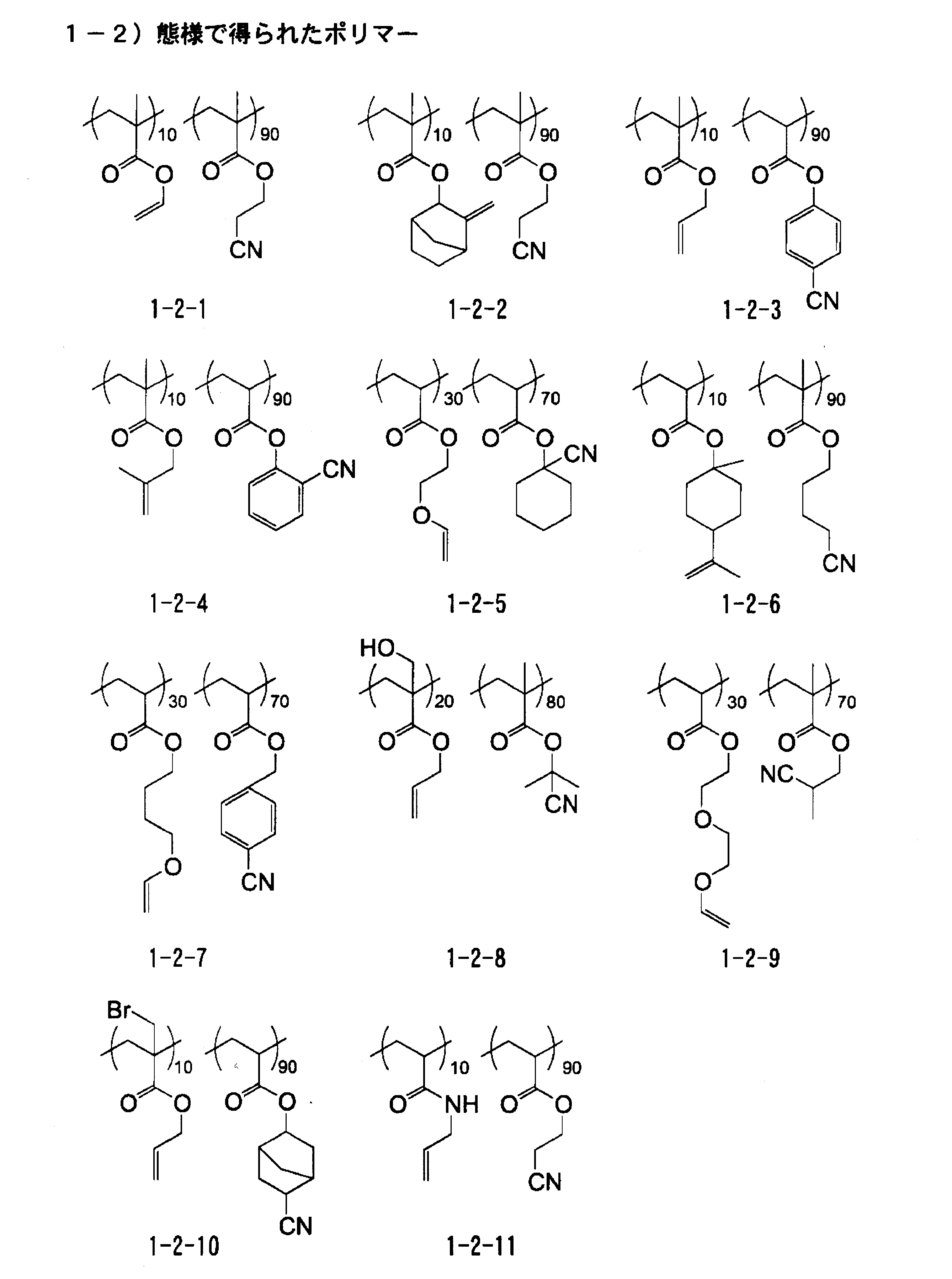


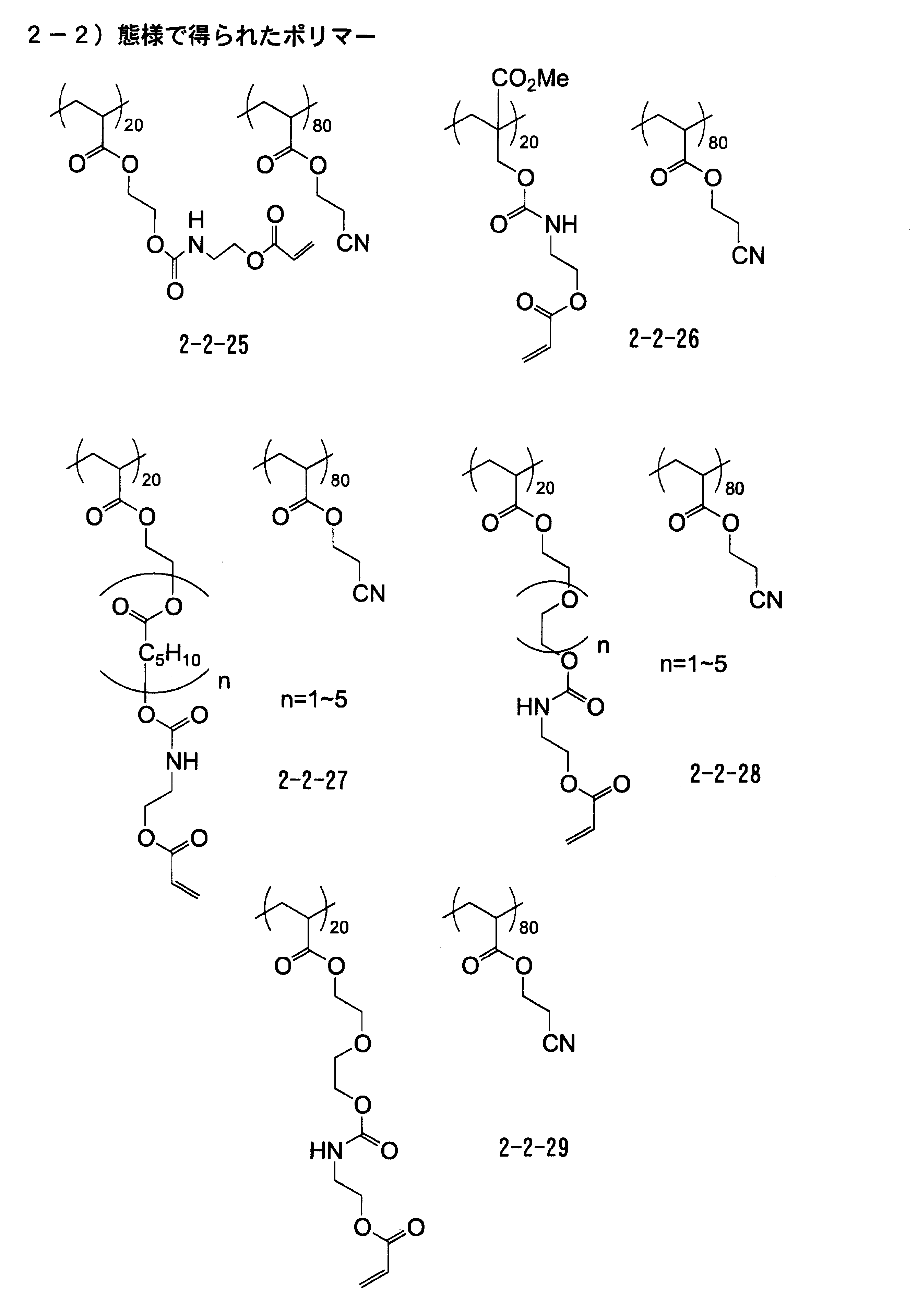
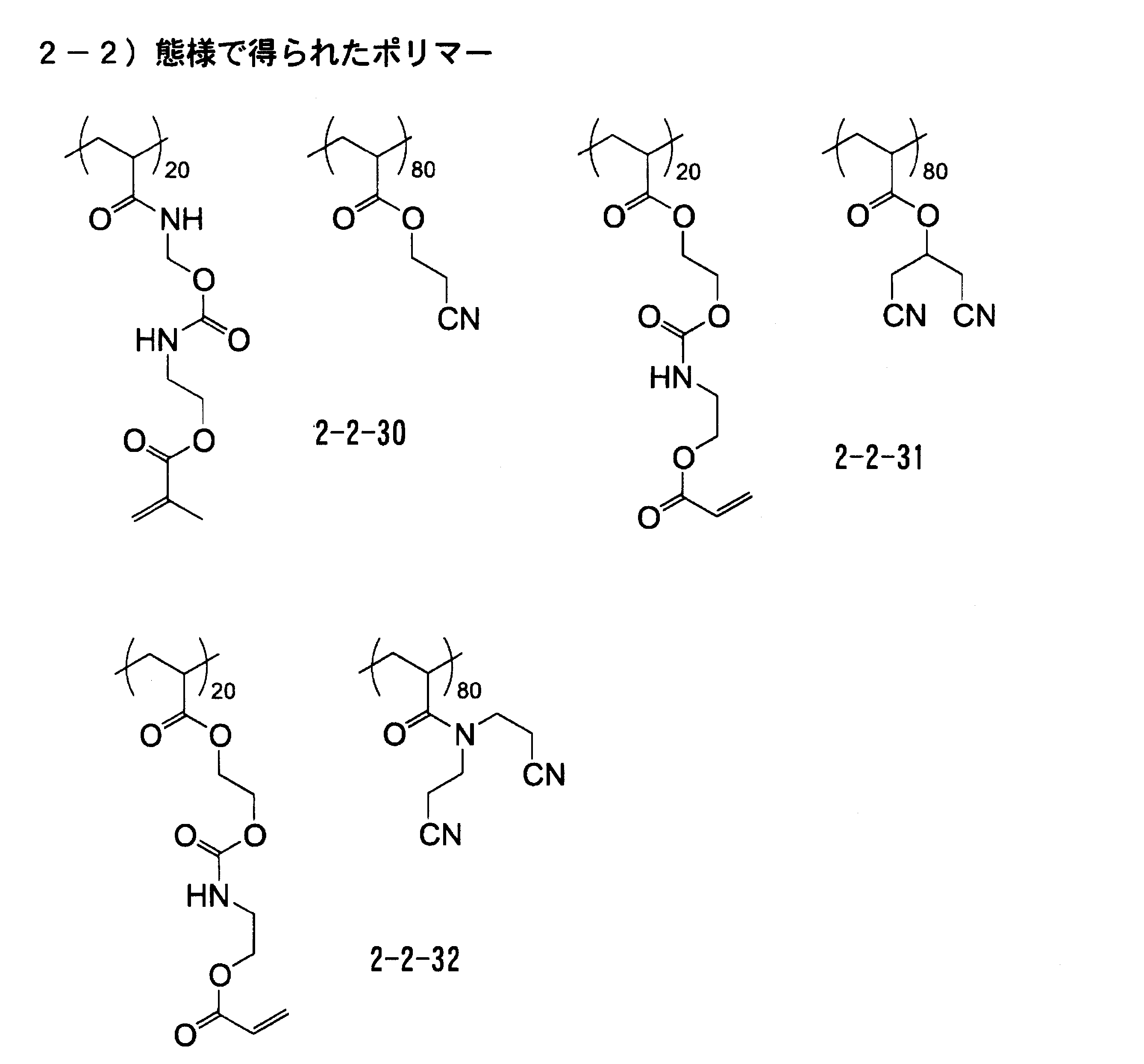
ここで、例えば、前記具体例の化合物2-2-11は、アクリル酸と2-シアノエチルアクリレートを、例えば、N-メチルピロリドンに溶解させ、重合開始剤として、例えば、アゾイソブチロニトリル(AIBN)を用いてラジカル重合を行い、その後、グリシジルメタクリレートをベンジルトリエチルアンモニウムクロライドのような触媒を用い、ターシャリーブチルハイドロキノンのような重合禁止剤を添加した状態で付加反応することで合成することができる。
また、例えば、前記具体例の化合物2-2-19は、以下のモノマーと、p-シアノベンジルアクリレートを、N、N-ジメチルアクリルアミドのような溶媒に溶解させ、アゾイソ酪酸ジメチルのような重合開始剤を用いてラジカル重合を行い、その後、トリエチルアミンのような塩基を用いて脱塩酸を行うことで合成することができる。
また、例えば、前記具体例の化合物2-2-19は、以下のモノマーと、p-シアノベンジルアクリレートを、N、N-ジメチルアクリルアミドのような溶媒に溶解させ、アゾイソ酪酸ジメチルのような重合開始剤を用いてラジカル重合を行い、その後、トリエチルアミンのような塩基を用いて脱塩酸を行うことで合成することができる。
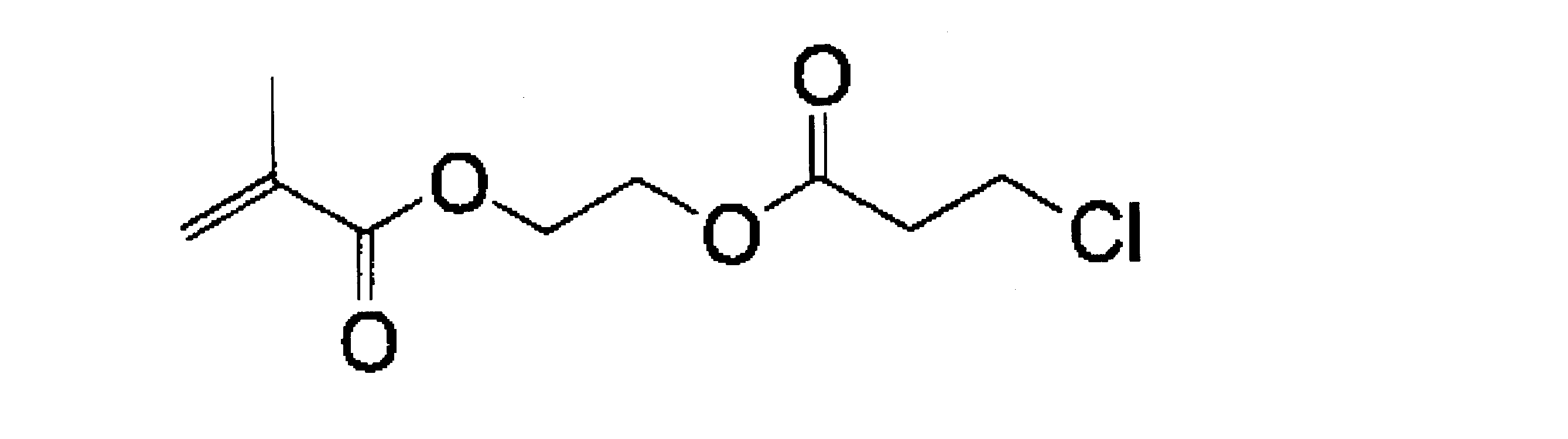
本発明におけるシアノ基含有重合性ポリマー等の重合性基及び相互作用性基を有する化合物は、重合性基と相互作用性基の他に、形成されためっき触媒又はその前駆体を受容しうる表面疎水性硬化物層が後述する条件1及び条件2を満たす範囲であれば、極性基を有していてもよい。
極性基を有していることによって、後述の工程により金属膜が形成された後、例えば、保護層を設ける場合には、ポリマー層と保護層との接触領域において密着力を向上させることができる。
極性基を有していることによって、後述の工程により金属膜が形成された後、例えば、保護層を設ける場合には、ポリマー層と保護層との接触領域において密着力を向上させることができる。
前述のように、本発明における表面疎水性硬化物層を形成するためには、重合性基及び相互作用性基を有するポリマー等の重合性基及び相互作用性基を有する化合物を含有する感光性樹脂組成物、即ち、重合性基及び相互作用性基を有する化合物と、これらの化合物を溶解しうる溶剤と、を含有する組成物(好ましくは、シアノ基又は-O-(CH2)n-O-(nは1~5の整数)で表される構造、及び重合性基を有するポリマーと、これら化合物を溶解しうる溶剤と、を含有する感光性樹脂組成物)を用いることが好ましい。
前記特定重合性化合物がポリマーである場合の重量平均分子量としては、1000以上70万以下が好ましく、更に好ましくは2000以上30万以下である。特に、重合感度の観点から、重量平均分子量は、20000以上であることが好ましい。また、重合度としては、10量体以上のものを使用することが好ましく、更に好ましくは20量体以上のものである。また、7000量体以下が好ましく、3000量体以下がより好ましく、2000量体以下が更に好ましく、1000量体以下が特に好ましい。
特定重合性化合物(例えば、シアノ基含有重合性化合物)の含有量は、感光性樹脂組成物に対して、固形分換算で2質量%~50質量%であることが好ましく、更に好ましくは 5質量%~20質量%の範囲である。
特定重合性化合物(例えば、シアノ基含有重合性化合物)の含有量は、感光性樹脂組成物に対して、固形分換算で2質量%~50質量%であることが好ましく、更に好ましくは 5質量%~20質量%の範囲である。
<溶剤>
感光性樹脂組成物には、前記特定重合性化合物に加え、溶剤を用いることができる。
本発明に使用しうる溶剤は、組成物の主成分である、重合性基及び相互作用性基を有する化合物が溶解可能ならば特に制限はない。溶剤には、更に界面活性剤を添加してもよい。
使用できる溶剤としては、例えば、メタノール、エタノール、プロパノール、エチレングリコール、グリセリン、プロピレングリコールモノメチルエーテル、エチレングリコールジメチルエーテルの如きアルコール系溶剤、酢酸の如き酸、アセトン、メチルエチルケトン、シクロヘキサノンの如きケトン系溶剤、ホルムアミド、ジメチルアセトアミド、N-メチルピロリドンの如きアミド系溶剤、アセトニトリル、プロピロニトリルの如きニトリル系溶剤、酢酸メチル、酢酸エチルの如きエステル系溶剤、ジメチルカーボネート、ジエチルカーボネートの如きカーボネート系溶剤などが挙げられる。
この中でも、特定重合性化合物として、シアノ基含有重合性ポリマーを用いる場合には、アミド系、ケトン系、ニトリル系溶剤、カーボネート系溶剤が好ましく、具体的には、アセトン、ジメチルアセトアミド、メチルエチルケトン、シクロヘキサノン、アセトニトリル、プロピオニトリル、N-メチルピロリドン、ジメチルカーボネートが好ましい。
また、シアノ基含有重合性ポリマーを含有する組成物を塗布する場合は、取り扱い容易性の観点から、沸点が50~150℃の溶剤が好ましい。なお、これらの溶剤は単一で使用してもよいし、混合して使用してもよい。
また、シアノ基含有重合性ポリマーを含有する組成物を塗布する場合は、取り扱い容易性の観点から、沸点が50~150℃の溶剤が好ましい。なお、これらの溶剤は単一で使用してもよいし、混合して使用してもよい。
本発明の感光性樹脂組成物を、基板上に塗布する場合、基板又はその上に設けられる密着補助層の溶媒吸収率が5~25%となる溶剤を選択することができる。この溶媒吸収率は、基板や、密着補助層を形成した基材を溶剤中に浸漬し、1000分後に引き上げた場合の質量の変化から求めることができる。
また、感光性樹脂組成物を、基板上に塗布する場合、基板の膨潤率が10~45%となる溶剤を選択してもよい。この膨潤率は、基板や、密着補助層を形成した基材を溶剤中に浸漬し、1000分後に引き上げた場合の厚さの変化から求めることができる。
なお、感光性樹脂組成物を溶剤で希釈し、塗布による膜形成を行う場合、塗布液中の固形分の含有量(重量%)によって形成した膜厚を制御することが可能である。好適な濃度としては、前記特定重合性化合物およびその他固形分添加物の総量で1~50重量%の範囲にて溶剤に希釈するのが好ましく、特に1μm以下の薄膜を形成する場合は1~20重量%の範囲にて溶剤に希釈して膜形成を行うことが好ましい。
必要に応じて溶剤に添加することのできる界面活性剤は、溶剤に溶解するものであればよく、そのような界面活性剤としては、例えば、n-ドデシルベンゼンスルホン酸ナトリウムの如きアニオン性界面活性剤や、n-ドデシルトリメチルアンモニウムクロライドの如きカチオン性界面活性剤、ポリオキシエチレンノニルフェノールエーテル(市販品としては、例えば、エマルゲン910、花王(株)製など)、ポリオキシエチレンソルビタンモノラウレート(市販品としては、例えば、商品名「ツイーン20」など)、ポリオキシエチレンラウリルエーテルの如き非イオン性界面活性剤等が挙げられる。
また、感光性樹脂組成物には、必要に応じて可塑剤を添加することもできる。使用できる可塑剤としては、一般的な可塑剤が使用でき、フタル酸エステル類(ジメチルフタレート、ジエチルフタレート、ジブチルフタレート、ジ-2-エチルヘキシルフタレート、ジノルマルオクチルフタレート、ジイソノニルフタレート、ジノニルフタレート、ジイソデシルフタレート、ブチルベンジルフタレート)、アジピン酸エステル類(ジオクチルアジペート、ジイソノニルアジペート)、アゼラインサンジオクチル、セバシンサンエステル類(ジブチルセバケート、ジオクチルセバケート)リン酸トリクレシル、アセチルクエン酸トリブチル、エポキシ化大豆油、トリメリット酸トリオクチル、塩素化パラフィンやジメチルアセトアミド、N-メチルピロリドンのような高沸点溶媒も使用することができる。
さらに、感光性樹脂組成物には、必要に応じて、重合禁止剤を添加することもできる。使用できる重合禁止剤としては、ハイドロキノン、ジターシャリーブチルハイドロキノン、2,5-ビス(1,1,3,3-テトラメチルブチル)ハイドロキノンなどのハイドロキノン類、p-メトキシフェノール、フェノールなどのフェノール類、ベンゾキノン類、TEMPO(2,2,6,6-テトラメチル-1-ピペリジニロキシ フリーラジカル)、4-ヒドロキシTEMPOなどのフリーラジカル類、フェノチアジン類、N-ニトロソフェニルヒドロキシアミン、そのアルミニウム塩などのニトロソアミン類、カテコール類を使用することができる。
さらに、ゴム成分(例えば、CTBNやNBRなど)、難燃化剤(例えば、りん系難燃化剤)、希釈剤やチキソトロピー化剤、顔料、消泡剤、レベリング剤、カップリング剤などを添加してもよい。
これら特定重合性化合物と各種の添加剤とを適宜混合した組成物を用いることで、形成されるめっき触媒又はその前駆体を受容性しうる表面疎水硬化物層の物性、例えば、熱膨張係数、ガラス転移温度、ヤング率、ポアソン比、破断応力、降伏応力、熱分解温度などを最適に設定することができる。特に、破断応力、降伏応力、熱分解温度については、より高い方が好ましい。
得られた硬化物層は、温度サイクル試験や熱経時試験、リフロー試験などで耐熱性を測定することができ、例えば、熱分解に関しては、200℃環境に1時間曝した場合の質量減少が20%以下であると、十分に耐熱性を有していると評価できる。
得られた硬化物層は、温度サイクル試験や熱経時試験、リフロー試験などで耐熱性を測定することができ、例えば、熱分解に関しては、200℃環境に1時間曝した場合の質量減少が20%以下であると、十分に耐熱性を有していると評価できる。
本発明の方法における第1の工程では、このような感光性樹脂組成物に含まれる前記各成分を適切な溶媒に溶解して調整し、適切な基板表面に塗布して感光性樹脂組成物塗膜を形成する。
基板上に感光性樹脂組成物を塗布する場合の塗布量は、めっき触媒又はその前駆体との充分な相互作用形成性の観点からは、固形分換算で、0.1~20g/m2が好ましく、特に1~6g/m2が好ましい。
基板上に、該感光性樹脂組成物を含有する塗布液を塗布し、乾燥させて、感光性樹脂組成物層を形成する場合、塗布と乾燥との間に、20~40℃で0.5~2時間放置させて、塗膜中に残存する溶剤を除去する工程を実施してもよい。
基板上に感光性樹脂組成物を塗布する場合の塗布量は、めっき触媒又はその前駆体との充分な相互作用形成性の観点からは、固形分換算で、0.1~20g/m2が好ましく、特に1~6g/m2が好ましい。
基板上に、該感光性樹脂組成物を含有する塗布液を塗布し、乾燥させて、感光性樹脂組成物層を形成する場合、塗布と乾燥との間に、20~40℃で0.5~2時間放置させて、塗膜中に残存する溶剤を除去する工程を実施してもよい。
<(2)パターン状に露光し、感光性樹脂組成物を硬化させて露光領域に表面疎水性硬化物層を形成する工程>
引き続き行われる第2工程では、該感光性樹脂組成物塗膜をパターン状に露光して、露光領域を硬化させ、表面疎水性硬化物層を形成する。
この露光工程により、露光領域において、基板表面に特定重合性化合物が直接化学結合し、めっき触媒又はその前駆体受容領域が形成される。
引き続き行われる第2工程では、該感光性樹脂組成物塗膜をパターン状に露光して、露光領域を硬化させ、表面疎水性硬化物層を形成する。
この露光工程により、露光領域において、基板表面に特定重合性化合物が直接化学結合し、めっき触媒又はその前駆体受容領域が形成される。
(表面グラフト)
基板上におけるめっき触媒受容性の表面疎水性硬化物層、一般的な表面グラフト重合と呼ばれる手段を用いて形成できる。グラフト重合とは、高分子化合物鎖上に活性種を与え、これによって重合を開始する別の単量体を更に重合させ、グラフト(接ぎ木)重合体を合成する方法である。特に、活性種を与える高分子化合物が固体表面を形成する時には、表面グラフト重合と呼ばれる。
基板上におけるめっき触媒受容性の表面疎水性硬化物層、一般的な表面グラフト重合と呼ばれる手段を用いて形成できる。グラフト重合とは、高分子化合物鎖上に活性種を与え、これによって重合を開始する別の単量体を更に重合させ、グラフト(接ぎ木)重合体を合成する方法である。特に、活性種を与える高分子化合物が固体表面を形成する時には、表面グラフト重合と呼ばれる。
本発明に適用される表面グラフト重合法としては、文献記載の公知の方法をいずれも使用することができる。例えば、新高分子実験学10、高分子学会編、1994年、共立出版(株)発行、p135には表面グラフト重合法として光グラフト重合法、プラズマ照射グラフト重合法が記載されている。また、吸着技術便覧、NTS(株)、竹内監修、1999.2発行、p203、p695には、γ線、電子線などの放射線照射グラフト重合法が記載されている。
光グラフト重合法の具体的方法としては、特開昭63-92658号公報、特開平10-296895号公報及び特開平11-119413号公報に記載の方法を使用することができる。
光グラフト重合法の具体的方法としては、特開昭63-92658号公報、特開平10-296895号公報及び特開平11-119413号公報に記載の方法を使用することができる。
本発明における表面疎水性硬化物層(めっき触媒受容性の硬化物層)を形成する際には、上記の表面グラフト法以外にも、高分子化合物鎖の末端に、トリアルコキシシリル基、イソシアネート基、アミノ基、水酸基、カルボキシル基などの反応性官能基を付与し、これと基板表面に存在する官能基とのカップリング反応により結合させる方法を適用することもできる。
これらの方法の中でも、より多くのグラフトポリマーを生成する観点からは、光グラフト重合法、特に、UV光による光グラフト重合法を用いて前記特定の相互作用性基を有するポリマーが基板に化学結合してなる表面疎水性硬化物層を形成することが好ましい。
これらの方法の中でも、より多くのグラフトポリマーを生成する観点からは、光グラフト重合法、特に、UV光による光グラフト重合法を用いて前記特定の相互作用性基を有するポリマーが基板に化学結合してなる表面疎水性硬化物層を形成することが好ましい。
〔基板〕
本発明における「基板」とは、その表面が、めっき触媒又はその前駆体と相互作用を形成する官能基を有する重合性化合物が直接化学結合した状態を形成しうる機能を有するものであり、基板を構成する基材自体がこのような表面特性を有するものであってもよく、また、該基材上に別途中間層を設け、該中間層がこのような特性を有するものであってもよい。
本発明における「基板」とは、その表面が、めっき触媒又はその前駆体と相互作用を形成する官能基を有する重合性化合物が直接化学結合した状態を形成しうる機能を有するものであり、基板を構成する基材自体がこのような表面特性を有するものであってもよく、また、該基材上に別途中間層を設け、該中間層がこのような特性を有するものであってもよい。
(基材、基板)
本発明に使用される基材は、特開2007-154369[0062]に記載の基材を使用することができる。これらの基材は寸法安定性や物理特性を向上させる観点でシリカなどの無機充填物を混合したものであっても良く、なかでもエポキシ樹脂、又はポリイミド樹脂、又は液晶ポリマー樹脂からなる樹脂を含む基材が好ましい。これらの基材は寸法安定性や物理特性を向上させる観点で無機充填物が混在してものであっても良い。
本発明における基板として、特開2005-281350号公報の段落番号[0028]~[0088]に記載の重合開始部位を骨格中に有するポリイミドを含む基材を用いることもできる。
本発明に使用される基材は、特開2007-154369[0062]に記載の基材を使用することができる。これらの基材は寸法安定性や物理特性を向上させる観点でシリカなどの無機充填物を混合したものであっても良く、なかでもエポキシ樹脂、又はポリイミド樹脂、又は液晶ポリマー樹脂からなる樹脂を含む基材が好ましい。これらの基材は寸法安定性や物理特性を向上させる観点で無機充填物が混在してものであっても良い。
本発明における基板として、特開2005-281350号公報の段落番号[0028]~[0088]に記載の重合開始部位を骨格中に有するポリイミドを含む基材を用いることもできる。
また、本発明の金属層付き基板の製造方法により得られた金属層付き基板は、半導体パッケージ、各種電気配線基板等に適用することができる。このような用途に用いる場合は、以下に示す、絶縁性樹脂を含んだ基板、具体的には、絶縁性樹脂からなる基板、又は、絶縁性樹脂からなる層を基材上に有する基板を用いることが好ましい。
絶縁性樹脂からなる基板、絶縁性樹脂からなる層を得る場合には、公知の絶縁性樹脂組成物が用いられる。この絶縁性樹脂組成物には、主たる樹脂に加え、目的に応じて種々の添加物を併用することができる。例えば、絶縁層の強度を高める目的で、多官能のアクリレートモノマーを添加することや、絶縁体層の強度を高め、電気特性を改良する目的で、無機、若しくは有機の粒子を添加する、などの手段をとることもできる。
なお、本発明における「絶縁性樹脂」とは、公知の絶縁膜や絶縁層に使用しうる程度の絶縁性を有する樹脂を意味するものである。即ち、完全な絶縁体でないものであっても、目的に応じた絶縁性を有する樹脂であれば、本発明に適用しうる。
なお、本発明における「絶縁性樹脂」とは、公知の絶縁膜や絶縁層に使用しうる程度の絶縁性を有する樹脂を意味するものである。即ち、完全な絶縁体でないものであっても、目的に応じた絶縁性を有する樹脂であれば、本発明に適用しうる。
絶縁性樹脂の具体例としては、例えば、熱硬化性樹脂でも熱可塑性樹脂でもまたそれらの混合物でもよく、例えば、特開2007-144820[0014]~[0019]に記載されているエポキシ樹脂、フェノール樹脂、ポリイミド樹脂、ポリエステル樹脂、ビスマレイミド樹脂、ポリオレフィン系樹脂、イソシアネート系樹脂、フェノキシ樹脂、ポリエーテルスルフォン、ポリスルフォン、ポリフェニレンスルフォン、ポリフェニレンサルファイド、ポリフェニルエーテル、ポリエーテルイミドなどを使用することができる。
絶縁性樹脂組成物には、架橋を進めるために重合性の二重結合を有する化合物のようなもの、具体的には、アクリレート、メタクリレート化合物を含有していてもよく、特に多官能のものが好ましい。そのほか、重合性の二重結合を有する化合物として、熱硬化性樹脂、若しくは熱可塑性樹脂、例えば、エポキシ樹脂、フェノール樹脂、ポリイミド樹脂、ポリオレフィン樹脂、フッ素樹脂等に、メタクリル酸やアクリル酸等を用い、樹脂の一部を(メタ)アクリル化反応させた樹脂を用いてもよい。
本発明における絶縁性樹脂組成物には、樹脂被膜の機械強度、耐熱性、耐候性、難燃性、耐水性、電気特性などの特性を強化するために、樹脂と他の成分とのコンポジット(複合素材)も使用することができる。複合化するのに使用される材料としては、紙、ガラス繊維、シリカ粒子、フェノール樹脂、ポリイミド樹脂、ビスマレイミドトリアジン樹脂、フッ素樹脂、ポリフェニレンオキサイド樹脂などを挙げることができる。
更に、この絶縁性樹脂組成物には必要に応じて一般の配線板用樹脂材料に用いられる充填剤、例えば、シリカ、アルミナ、クレー、タルク、水酸化アルミニウム、炭酸カルシウムなどの無機フィラー、硬化エポキシ樹脂、架橋ベンゾグアナミン樹脂、架橋アクリルポリマーなどの有機フィラーを一種又は二種以上配合してもよい。中でも、充填材としてはシリカを用いることが好ましい。
また、更に、この絶縁性樹脂組成物には、必要に応じて着色剤、難燃剤、接着性付与剤、シランカップリング剤、酸化防止剤、紫外線吸収剤、などの各種添加剤を一種又は二種以上添加してもよい。
また、更に、この絶縁性樹脂組成物には、必要に応じて着色剤、難燃剤、接着性付与剤、シランカップリング剤、酸化防止剤、紫外線吸収剤、などの各種添加剤を一種又は二種以上添加してもよい。
これらの材料を絶縁性樹脂組成物に添加する場合は、いずれも、樹脂に対して、1~200質量%の範囲で添加されることが好ましく、より好ましくは10~80質量%の範囲で添加される。この添加量が、1質量%未満である場合は、上記の特性を強化する効果がなく、また、200質量%を超えると場合には、樹脂特有の強度などの特性が低下する。
このような用途に用いる場合の基板として、具体的には、1GHzにおける誘電率(比誘電率)が3.5以下である絶縁性樹脂からなる基板であるか、又は、該絶縁性樹脂からなる層を基材上に有する基板であることが好ましい。また、1GHzにおける誘電正接が0.01以下である絶縁性樹脂からなる基板であるか、又は、該絶縁性樹脂からなる層を基材上に有する基板であることが好ましい。
絶縁性樹脂の誘電率及び誘電正接は、常法により測定することができる。例えば、「第18回エレクトロニクス実装学会学術講演大会要旨集」、2004年、p189、に記載の方法に基づき、空洞共振器摂動法(例えば、極薄シート用εr、tanδ測定器、キーコム株式会社製)を用いて測定することができる。
このように、本発明においては誘電率や誘電正接の観点から絶縁樹脂材料を選択することも有用である。誘電率が3.5以下であり、誘電正接が0.01以下の絶縁性樹脂としては、液晶ポリマー、ポリイミド樹脂、フッ素樹脂、ポリフェニレンエーテル樹脂、シアネートエステル樹脂、ビス(ビスフェニレン)エタン樹脂などが挙げられ、更にそれらの変性樹脂も含まれる。
本発明に用いられる基板は、半導体パッケージ、各種電気配線基板等への用途を考慮すると、表面凹凸が500nm以下であることが好ましく、より好ましくは100nm以下、更に好ましくは50nm以下、最も好ましくは20nm以下である。表面凹凸の値は、算術平均粗さRa(JISB0633-2001)により求められる。この基板の表面凹凸(中間層や重合開始層が設けられている場合はその層の表面凹凸)が小さくなるほど、得られた金属パターン材料を配線等に適用した場合に、高周波送電時の電気損失が少なくなり好ましい。
なお、基板の両面に本発明に用いられる感光性樹脂組成物を塗布し、両面にめっき触媒を吸着させ、その後、めっきを行って両面にパターン状の金属層を形成することも可能である。
なお、基板の両面に本発明に用いられる感光性樹脂組成物を塗布し、両面にめっき触媒を吸着させ、その後、めっきを行って両面にパターン状の金属層を形成することも可能である。
なお、基板表面に表面疎水性硬化物層と基板との密着性を向上させる目的で以下に示すような密着補助層を形成することもできる。
(密着補助層)
密着補助層としては、基板との密着性が良好な樹脂組成物、及び、感光性樹脂組成物により形成される樹脂膜と相互作用を形成し得る活性点を発生させる活性種(化合物)を用いて形成されることが好ましい。なお、樹脂組成物を構成する樹脂が、めっき触媒吸着能を有する樹脂膜と相互作用を形成し得る活性点を発生させる部位を有する場合には、活性種(化合物)を別途添加する必要はない。
(密着補助層)
密着補助層としては、基板との密着性が良好な樹脂組成物、及び、感光性樹脂組成物により形成される樹脂膜と相互作用を形成し得る活性点を発生させる活性種(化合物)を用いて形成されることが好ましい。なお、樹脂組成物を構成する樹脂が、めっき触媒吸着能を有する樹脂膜と相互作用を形成し得る活性点を発生させる部位を有する場合には、活性種(化合物)を別途添加する必要はない。
本発明における密着補助層としては、例えば、基材が、多層積層板、ビルドアップ基板、若しくはフレキシブル基板の材料として用いられてきた公知の絶縁樹脂からなる場合には、該基材との密着性の観点から、密着補助層を形成する際に用いられる樹脂組成物としても、絶縁樹脂組成物が用いられることが好ましい。
以下、基材が絶縁樹脂からなり、密着補助層が絶縁樹脂組成物から形成される態様について説明する。
以下、基材が絶縁樹脂からなり、密着補助層が絶縁樹脂組成物から形成される態様について説明する。
密着補助層を形成する際に用いられる絶縁樹脂組成物は、基材を構成する電気的絶縁性の樹脂と同じものを含んでいてもよく、異なっていてもよいが、ガラス転移点や弾性率、線膨張係数といった熱物性が近いものを使用することが好ましい。具体的には、例えば、基材を構成する絶縁樹脂と同じ種類の絶縁樹脂を使用することが密着の点で好ましい。
また、これ以外の成分として、密着補助層の強度を高める、また、電気特性を改良するために、無機若しくは有機の粒子を添加してもよい。
また、これ以外の成分として、密着補助層の強度を高める、また、電気特性を改良するために、無機若しくは有機の粒子を添加してもよい。
なお、本発明の密着補助層に使用される絶縁樹脂とは、公知の絶縁膜に使用しうる程度の絶縁性を有する樹脂を意味するものであり、完全な絶縁体でないものであっても、目的に応じた絶縁性を有する樹脂であれば、本発明に適用しうる。
絶縁樹脂の具体例としては、例えば、熱硬化性樹脂でも熱可塑性樹脂でもまたそれらの混合物でもよく、例えば、熱硬化性樹脂としては、エポキシ樹脂、フェノール樹脂、ポリイミド樹脂、ポリエステル樹脂、ビスマレイミド樹脂、ポリオレフィン系樹脂、シソシアネート系樹脂等が挙げられる。熱可塑性樹脂としては、例えば、フェノキシ樹脂、ポリエーテルスルフォン、ポリスルフォン、ポリフェニレンスルフォン、ポリフェニレンサルファイド、ポリフェニルエーテル、ポリエーテルイミド等が挙げられる。
熱可塑性樹脂と熱硬化性樹脂とは、それぞれ単独で用いてもよいし、2種以上併用してもよい。
絶縁樹脂の具体例としては、例えば、熱硬化性樹脂でも熱可塑性樹脂でもまたそれらの混合物でもよく、例えば、熱硬化性樹脂としては、エポキシ樹脂、フェノール樹脂、ポリイミド樹脂、ポリエステル樹脂、ビスマレイミド樹脂、ポリオレフィン系樹脂、シソシアネート系樹脂等が挙げられる。熱可塑性樹脂としては、例えば、フェノキシ樹脂、ポリエーテルスルフォン、ポリスルフォン、ポリフェニレンスルフォン、ポリフェニレンサルファイド、ポリフェニルエーテル、ポリエーテルイミド等が挙げられる。
熱可塑性樹脂と熱硬化性樹脂とは、それぞれ単独で用いてもよいし、2種以上併用してもよい。
また、密着補助層に用いられる絶縁樹脂としては、めっき触媒受容性の感光性樹脂組成物と相互作用を形成し得る活性点を発生させる骨格を有する樹脂を用いることもできる。例えば、特開2005-307140号公報の段落番号〔0018〕~〔0078〕に記載の重合開始部位を骨格中に有するポリイミドが用いられる。
更に、密着補助層には、層内での架橋を進めるために重合性の二重結合を有する化合物、具体的には、アクリレート、メタクリレート化合物を含有していてもよく、特に、多官能のものを用いることが好ましい。その他、重合性の二重結合を有する化合物として、熱硬化性樹脂、若しくは熱可塑性樹脂、例えば、エポキシ樹脂、フェノール樹脂、ポリイミド樹脂、ポリオレフィン樹脂、フッ素樹脂等に対し、その一部を、メタクリル酸やアクリル酸等を用いて、(メタ)アクリル化反応させた樹脂を用いてもよい。
本発明における密着補助層は、本発明の効果を損なわない限りにおいて、目的に応じて、種々の化合物を添加することができる。
具体的には、例えば、加熱時に応力を緩和させることができる、ゴム、SBRラテックスのような物質、膜性改良のためのバインダー、可塑剤、界面活性剤、粘度調整剤などが挙げられる。
具体的には、例えば、加熱時に応力を緩和させることができる、ゴム、SBRラテックスのような物質、膜性改良のためのバインダー、可塑剤、界面活性剤、粘度調整剤などが挙げられる。
また、本発明における密着補助層には、樹脂被膜の機械強度、耐熱性、耐候性、難燃性、耐水性、電気特性などの特性を強化するために、樹脂と他の成分とのコンポジット(複合素材)も使用することができる。複合化するのに使用される材料としては、紙、ガラス繊維、シリカ粒子、フェノール樹脂、ポリイミド樹脂、ビスマレイミドトリアジン樹脂、フッ素樹脂、ポリフェニレンオキサイド樹脂などを挙げることができる。
更に、この密着補助層には、必要に応じて、一般の配線板用樹脂材料に用いられる充填剤、例えば、シリカ、アルミナ、クレー、タルク、水酸化アルミニウム、炭酸カルシウムなどの無機フィラー、硬化エポキシ樹脂、架橋ベンゾグアナミン樹脂、架橋アクリルポリマーなどの有機フィラーを一種又は二種以上配合してもよい。
また、更にこの密着補助層には、必要に応じて、着色剤、難燃剤、接着性付与剤、シランカップリング剤、酸化防止剤、紫外線吸収剤などの各種添加剤を、一種又は二種以上添加してもよい。
また、更にこの密着補助層には、必要に応じて、着色剤、難燃剤、接着性付与剤、シランカップリング剤、酸化防止剤、紫外線吸収剤などの各種添加剤を、一種又は二種以上添加してもよい。
これらの材料を添加する場合は、いずれも、主成分となる樹脂に対して、0~200質量%の範囲で添加されることが好ましく、より好ましくは0~80質量%の範囲で添加される。密着補助層と隣接する基材とが、熱や電気に対して同じ若しくは近い物性値を示す場合には、これら添加物は必ずしも添加する必要はない。添加物を、樹脂に対して200質量%を超える範囲で用いる場合には、樹脂自体が本来有する強度などの特性が低下する懸念がある。
密着補助層には、前述のように、前記感光性樹脂組成物と相互作用を形成し得る活性点を発生させる活性種(化合物)が用いられることが好ましい。この活性点を発生させるためには、何らかのエネルギーを付与すればよく、好ましくは、光(紫外線、可視光線、X線など)、プラズマ(酸素、窒素、二酸化炭素、アルゴンなど)、熱、電気、等が用いられる。更に、酸化性の液体(過マンガン酸カリウム溶液)などによって表面を化学的に分解することで活性点を発生させてもよい。
活性種の例としては、前述した樹脂フィルム(基材)中に添加される熱重合開始剤、光重合開始剤が挙げられる。ここで、密着補助層に含有させる重合開始剤の量は、固形分で0.1~50質量%であることが好ましく、1.0~30質量%であることがより好ましい。
活性種の例としては、前述した樹脂フィルム(基材)中に添加される熱重合開始剤、光重合開始剤が挙げられる。ここで、密着補助層に含有させる重合開始剤の量は、固形分で0.1~50質量%であることが好ましく、1.0~30質量%であることがより好ましい。
本発明における密着補助層の厚みは、一般に、0.1μm~10μmの範囲であり、0.2μm~5μmの範囲であることが好ましい。密着補助層を設ける場合、厚みが上記一般的な範囲であれば、隣接する基材や金属イオン吸着能を有する樹脂膜との十分な密着強度が得られ、また、一般の接着剤を用いるのに比較して薄層でありながら、その接着剤による層と同様の密着性が達成される。その結果、全体の厚みが薄く、且つ、密着性に優れた両面金属膜付きフィルムを得ることができる。
また、本発明における密着補助層の表面は、形成されるめっき金属膜の物性を向上させる観点から、JIS B 0601(1994年)、10点平均高さ法で測定した表面粗さRzが3μm以下であるものが好ましく、Rzが1μm以下であることがより好ましい。密着補助層の表面平滑性が上記値の範囲内、即ち、平滑性が高い状態であれば、回路が極めて微細な(例えば、ライン/スペースの値が25/25μm以下の回路パターン)プリント配線板を製造する際に、好適に用いられる。
密着補助層は樹脂フィルム(基材)の片面(感光性樹脂組成物塗膜が形成される面)に、塗布法、転写法、印刷法などの公知の層形成方法を適用して形成される。
また、密着補助層は基板上に形成後、何らかのエネルギーを与えて硬化処理工程をおこなってもよい。与えるエネルギーとしては、光、熱、圧力、電子線などが挙げられるが、本実施形態においては熱又は光が一般的であり、熱の場合は、100℃~300℃の熱を5分~120分加えることが好ましい。また、加熱硬化の条件は、樹脂フィルム(基材)の材料の種類、密着補助層を構成する樹脂組成物の種類等で異なり、これらの素材の硬化温度にもよるが、120~220℃で20分~120分の範囲で選択されることが好ましい。
この硬化処理工程は密着補助層の形成後すぐにおこなってもよく、密着補助層形成後に5~10分程度の予備硬化処理を行っておけば、密着補助層形成後に行われる他のすべてのそれぞれの工程を行ったあとに実施してもよい。
この硬化処理工程は密着補助層の形成後すぐにおこなってもよく、密着補助層形成後に5~10分程度の予備硬化処理を行っておけば、密着補助層形成後に行われる他のすべてのそれぞれの工程を行ったあとに実施してもよい。
密着補助層の形成後、その表面に形成される感光性樹脂組成物により形成される表面疎水性硬化物層との密着性向上の目的で、乾式及び/又は湿式法により表面を粗化してもよい。乾式粗化法としては、バフ、サンドブラスト、等の機械的研磨やプラズマエッチング等が挙げられる。一方、湿式粗化法としては、過マンガン酸塩、重クロム酸塩、オゾン、過酸化水素/硫酸、硝酸、等の酸化剤や、強塩基や樹脂膨潤溶剤を用いる方法等の化学薬品処理が挙げられる。
(露光)
パターン状の露光手段としては、一般にマスクを介したパターン状の露光手段が用いられるが、各種レーザなどによる走査露光を用いることもできる。
露光光源としては、例えば、UVランプ、可視光線などがあり、水銀灯、メタルハライドランプ、キセノンランプ、ケミカルランプ、カーボンアーク灯、等が挙げられる。放射線としては、電子線、X線、イオンビーム、遠赤外線などがある。また、g線、i線、Deep-UV光、高密度エネルギービーム(レーザービーム)も使用される。
一般的に用いられる具体的な態様としては、赤外線レーザーによる走査露光、マスクを介して行われるキセノン放電灯などの高照度フラッシュ露光や赤外線ランプ露光などが好適に挙げられる。
露光に要する時間としては、目的とする特定ポリマーと基板のとの結合性、結合量及び光源の光強度により異なるが、通常、5秒~1時間の間である。
露光パワーは、表面グラフト重合を容易に進行させる、生成されたグラフトポリマーの分解を抑制する、などの特性を考慮して選択すれば、10mJ/cm2~5000mJ/cm2の範囲であることが好ましく、より好ましくは、50mJ/cm2~3000mJ/cm2の範囲である。
なお、このとき、重合性基及び相互作用性基を有するポリマーとして、平均分子量2万以上、重合度200量体以上のポリマーを使用すると、低エネルギーの露光でグラフト重合が容易に進行するため、生成したグラフトポリマーの分解を更に抑制することができる。
感光性樹脂組成物を硬化させて形成しためっき触媒受容性の表面疎水性硬化物層は、露光して硬化させた後は、塗布ムラによる表面凹凸が解消し、硬膜後の樹脂表面が極めて平滑となる。このような平滑面を有するめっき触媒受容性の硬化物層であっても、相互作用性基の機能により、めっき触媒と配位結合性の強固、且つ、不可逆的な相互作用が形成されるため、ここに吸着されるめっき触媒等を基点とするめっきを行って形成された金属膜との良好な密着性も達成できる。
<(3)現像液により該感光性樹脂組成物の未硬化物を除去してパターン状の表面疎水性硬化物層を形成する工程>
本発明の第3の工程では、第2の工程で形成されためっき触媒受容性の表面疎水性硬化物層を未形成部部分(未露光部)における硬化していない感光性樹脂組成物を除去する工程である。
未硬化領域を現像で除去することでパターン状のめっき触媒受容性表面疎水性硬化物層の形成が完了する。
本発明の第3の工程では、第2の工程で形成されためっき触媒受容性の表面疎水性硬化物層を未形成部部分(未露光部)における硬化していない感光性樹脂組成物を除去する工程である。
未硬化領域を現像で除去することでパターン状のめっき触媒受容性表面疎水性硬化物層の形成が完了する。
現像は、得られた表面疎水性硬化物層が、例えば、pH12のアルカリ性溶液に添加し、1時間攪拌したときの重合性基部位の分解が50%以下である場合は、高アルカリ性溶液を現像液として用いることができる。
高アルカリ性現像液を用いる場合には、浸漬時間(現像時間)は1分~30分程度である。
また、他の現像方法として、重合性基及び相互作用性基(シアノ基)を有する化合物などのめっき触媒受容性の硬化物層を形成するために用いられる材料を溶解しうる溶剤(例えばアセトニトリル、アセトン、ジメチルカーボネート)を現像液とし、それに浸漬する方法が挙げられる。溶剤を用いる場合の浸漬時間は1分~30分が好ましい。
高アルカリ性現像液を用いる場合には、浸漬時間(現像時間)は1分~30分程度である。
また、他の現像方法として、重合性基及び相互作用性基(シアノ基)を有する化合物などのめっき触媒受容性の硬化物層を形成するために用いられる材料を溶解しうる溶剤(例えばアセトニトリル、アセトン、ジメチルカーボネート)を現像液とし、それに浸漬する方法が挙げられる。溶剤を用いる場合の浸漬時間は1分~30分が好ましい。
この特定ポリマーの好ましい態様として挙げたシアノ基を有するポリマーからなる表面疎水性硬化物層を形成する場合でも重合性基及び相互作用性基を有する化合物として、重合性基及びシアノ基を有する化合物を用いる以外は同様の方法が用いられ、また、好ましい態様も同様である。
本発明の方法において、第1工程から第3工程を経て得られたパターン状のめっき触媒受容性の表面疎水性硬化物層を構成する化合物は、めっき触媒又はその前駆体と相互作用を形成する官能基として、好ましくはシアノ基を有する。このシアノ基は、前述の通り、極性が高く、めっき触媒等とのあいだで配位結合性の相互作用を形成するため、これらの吸着能が高いが、解離性の極性基(親水性基)のように高い吸水性、親水性を有するものではなく、このシアノ基を有する特定ポリマーからなるめっき触媒受容性の硬化物層は、吸水性が低く、且つ、疎水性が高いものとなる。
このため、当該表面疎水性硬化物層は、以下の2つの条件を満たす疎水性を発現することになる。
条件1:25℃-50%相対湿度環境下における飽和吸水率が0.01~10質量%
条件2:25℃-95%相対湿度環境下における飽和吸水率が0.05~20質量%
このため、当該表面疎水性硬化物層は、以下の2つの条件を満たす疎水性を発現することになる。
条件1:25℃-50%相対湿度環境下における飽和吸水率が0.01~10質量%
条件2:25℃-95%相対湿度環境下における飽和吸水率が0.05~20質量%
以下、上記1~2の各条件について説明する。
条件1、条件2における飽和吸水率及び吸水率は、以下の方法にて測定することができる。
まず、基板を減圧乾燥機内に放置し、基板内に含まれる水分を除去した後、所望の温度及び湿度に設定された恒温恒湿槽内に放置し、質量変化の測定によって吸水率を測定する。ここで、条件1、2における飽和吸水率は、質量が24時間経過後も変化しなくなった時の吸水率を示している。別途、この飽和吸水率を測定した基板の上に前記表面疎水性硬化物層を形成した積層体についても、同様の操作により積層体の飽和吸水率を測定することにより、基板の飽和吸水率と積層体の飽和吸水率との差分により表面疎水性硬化物層の飽和吸水率を測定することができる。基板が密着補助層を有する場合も密着補助層を有しない場合も同様の方法で飽和吸水率を測定することができる。また、表面疎水性硬化物層を基板上に付与せずに、シャーレなどを用いて、表面疎水性硬化物層を構成する感光性樹脂組成物の単独膜を作製し、得られたポリマー単独膜を、上記の方法によって直接飽和吸水率を測定してもよい。
<(4)パターン状の表面疎水性硬化物層を形成した基板に、めっき触媒又はその前駆体と有機溶剤とを含有する水性めっき触媒液を接触させる工程>
本発明の第4の工程では、前記のようにして得られたパターン状の表面疎水性硬化物層を形成した基板をめっき触媒又はその前駆体及び有機溶剤を含有する水性めっき液に浸漬して、パターン状にめっき触媒又はその前駆体を吸着させる。
本工程においては、表面疎水性硬化物層を構成する表面グラフトポリマーが有する相互作用性基(シアノ基)が、その機能に応じて、付与されためっき触媒又はその前駆体を付着(吸着)する。
付与されるめっき触媒又はその前駆体としては、後述する(5)めっき工程における、めっきの触媒や電極として機能するものが挙げられる。そのため、めっき触媒又はその前駆体は、(5)めっき工程におけるめっきの種類により決定される。
通常は、本工程において用いられるめっき触媒又はその前駆体は、無電解めっき触媒又はその前駆体であることが好ましいが、本発明の係る表面疎水性硬化物層が十分なめっき触媒を吸着させうることから、これら吸着しためっき触媒を還元工程により金属化し、その金属からなる金属層を通電層として電気めっきを行うことも可能である。
〔めっき触媒液〕
本工程に好適に用いられる本発明の水性めっき触媒液は、めっき工程に適して選択されためっき触媒又はその前駆体と有機溶剤とを含有する。
まず、めっき触媒について述べる。
本工程に好適に用いられる本発明の水性めっき触媒液は、めっき工程に適して選択されためっき触媒又はその前駆体と有機溶剤とを含有する。
まず、めっき触媒について述べる。
((a)無電解めっき触媒)
本発明において用いられる無電解めっき触媒は、無電解めっき時の活性核となるものであれば、如何なるものも用いることができ、具体的には、自己触媒還元反応の触媒能を有する金属(NiまたはNiよりイオン化傾向の低い無電解めっきできる金属として知られるもの)などが挙げられ、具体的には、Pd、Ag、Cu、Ni、Al、Fe、Coなどが挙げられる。中でも、多座配位可能なものが好ましく、特に、配位可能な官能基の種類数、触媒能の高さから、Pdが特に好ましい。
この無電解めっき触媒は、通常金属コロイドとして用いられる。一般に、金属コロイドは、荷電を持った界面活性剤又は荷電を持った保護剤が存在する溶液中において、金属イオンを還元することにより作製することができる。金属コロイドの荷電は、ここで使用される界面活性剤又は保護剤により調節することができる。
((b)無電解めっき触媒前駆体)
本工程において用いられる無電解めっき触媒前駆体とは、化学反応により無電解めっき触媒となりうるものであれば、特に制限なく使用することができる。主には、上記無電解めっき触媒として挙げた金属の金属イオンが用いられる。無電解めっき触媒前駆体である金属イオンは、還元反応により無電解めっき触媒である0価金属になる。無電解めっき触媒前駆体である金属イオンは、ポリマー層へ付与した後、無電解めっき浴への浸漬前に、別途還元反応により0価金属に変化させて無電解めっき触媒としてもよいし、無電解めっき触媒前駆体のまま無電解めっき浴に浸漬し、無電解めっき浴中の還元剤により金属(無電解めっき触媒)に変化させてもよい。金属錯体の形で用いられても良い。
本工程において用いられる無電解めっき触媒前駆体とは、化学反応により無電解めっき触媒となりうるものであれば、特に制限なく使用することができる。主には、上記無電解めっき触媒として挙げた金属の金属イオンが用いられる。無電解めっき触媒前駆体である金属イオンは、還元反応により無電解めっき触媒である0価金属になる。無電解めっき触媒前駆体である金属イオンは、ポリマー層へ付与した後、無電解めっき浴への浸漬前に、別途還元反応により0価金属に変化させて無電解めっき触媒としてもよいし、無電解めっき触媒前駆体のまま無電解めっき浴に浸漬し、無電解めっき浴中の還元剤により金属(無電解めっき触媒)に変化させてもよい。金属錯体の形で用いられても良い。
実際には、無電解めっき前駆体である金属イオンは、金属塩を用いてめっき触媒受容性の硬化物層上に付与する。使用される金属塩としては、適切な溶媒に溶解して金属イオンと塩基(陰イオン)とに解離されるものであれば特に制限はなく、M(NO3)n、MCln、M2/n(SO4)、M3/n(PO4)(Mは、n価の金属原子を表す)などが挙げられる。金属イオンとしては、上記の金属塩が解離したものを好適に用いることができる。具体例としては、例えば、Agイオン、Cuイオン、Alイオン、Niイオン、Coイオン、Feイオン、Pdイオンが挙げられ、中でも、多座配位可能なものが好ましく、特に、配位可能な官能基の種類数、及び触媒能の点で、Pdイオンが好ましい。
((c)その他の触媒)
本発明において、後述する(5)めっき工程において、めっき触媒を密に付与して導電性を持たせためっき触媒受容性の硬化物層に対して、無電解めっきを行わず直接電気めっきを行うために用いられる触媒としては、0価金属を使用することができる。この0価金属としては、Pd、Ag、Cu、Ni、Al、Fe、Coなどが挙げられ、中でも、多座配位可能なものが好ましく、特に、特に、相互作用性基(シアノ基)に対する吸着(付着)性、触媒能の高さから、Pd、Ag、Cuが好ましい。
本発明において、後述する(5)めっき工程において、めっき触媒を密に付与して導電性を持たせためっき触媒受容性の硬化物層に対して、無電解めっきを行わず直接電気めっきを行うために用いられる触媒としては、0価金属を使用することができる。この0価金属としては、Pd、Ag、Cu、Ni、Al、Fe、Coなどが挙げられ、中でも、多座配位可能なものが好ましく、特に、特に、相互作用性基(シアノ基)に対する吸着(付着)性、触媒能の高さから、Pd、Ag、Cuが好ましい。
めっき触媒液へのめっき触媒又はその前駆体の添加量は、目的に応じて適宜、決定されるが、一般的には、0.01~10質量%の範囲であることが好ましく、0.1~5質量%の範囲であることがより好ましく、0.5~2質量%の範囲であることが最も好ましい。添加量が上記範囲において、所望のめっき触媒受容性領域への十分なめっき触媒又はその前駆体の吸着性と、基材露出領域への表層付着抑制がバランスし、優れた選択的めっき触媒吸着が達成されるため、その後のめっき工程により形成される金属層パターンとして高精細のパターン形成が可能となる。
(有機溶剤)
本発明の水性めっき触媒液には、有機溶剤を含有する。この有機溶剤を含有することで、前記疎水性硬化物層に対する浸透性が向上し、硬化物層が有する相互作用性基に効率よくめっき触媒又はその前駆体を吸着させることができる。
本工程でめっき触媒液の調製に用いられる溶剤としては、前記感光性樹脂組成物により形成された硬化物層に浸透しうる溶剤であれば特に制限は無いが、めっき触媒液の主たる溶媒(分散媒)として一般に水が用いられることから、水溶性の有機溶剤、即ち、水と任意の比率で均一に溶解しうる有機溶剤であることが好ましい。但し、一般的に「非水性」の有機溶剤であっても、水を主成分とする限りは後述する溶剤含有量範囲で溶解する場合は、水溶性の有機溶剤だけに限定されず、「非水性」の有機溶剤も使用することができる。
実施形態においては、具体的には、アセト酢酸メチル、アセト酢酸エチル,エチレングリコールジアセテート,シクロヘキサノン,アセチルアセトン,アセトフェノン,2-(1-シクロヘキセニル),プロピレングリコールジアセテート,トリアセチン,ジエチレングリコールジアセテート,ジオキサン,N-メチルピロリドン,ジメチルカーボネート、ジメチルセロソルブなどを用いることができる。特に前記めっき触媒またはその前駆体、および前記疎水性硬化物層との相溶性の観点ではアセトン、ジメチルカーボネート、ジメチルセロソルブが好ましい。
また、その他の併用可能な溶剤としては、ダイアセトンアルコール、γブチロラクトン、メタノール、エタノール、イソプロピルアルコール、ノルマルプロピルアルコール、プロピレングリコールモノメチルエーテル、メチルセロソルブ、エチルセロソルブ、エチレングリコールターシャリーブチルエーテル、テトラヒドロフラン、1,4-ジオキサン、n-メチル-2-ピロリドンなどが挙げられる。なお、上記した例示溶媒に含まれる「非水性」の溶剤については、水への溶解限界までの混入であれば許容される。例えば、ジメチルカーボネートの場合は12.5%まで、トリアセチンの場合は7.2%まで、シクロヘキサノンの場合は9%まで水との混合が可能である。
また、その他の併用可能な溶剤としては、ダイアセトンアルコール、γブチロラクトン、メタノール、エタノール、イソプロピルアルコール、ノルマルプロピルアルコール、プロピレングリコールモノメチルエーテル、メチルセロソルブ、エチルセロソルブ、エチレングリコールターシャリーブチルエーテル、テトラヒドロフラン、1,4-ジオキサン、n-メチル-2-ピロリドンなどが挙げられる。なお、上記した例示溶媒に含まれる「非水性」の溶剤については、水への溶解限界までの混入であれば許容される。例えば、ジメチルカーボネートの場合は12.5%まで、トリアセチンの場合は7.2%まで、シクロヘキサノンの場合は9%まで水との混合が可能である。
溶剤の含有量は、めっき触媒液全量に対して0.5~40質量%が好ましく、5~30質量%であることがより好ましく、5~20質量%の範囲であることが特に好ましい。溶剤の含有量が、上記範囲において、露出した基板領域(硬化物層未形成領域)へのめっき触媒の浸透や、基板に対する所望されない溶解、侵食が抑制されるにもかかわらず、触媒受容性を有する表面疎水性硬化物層への触媒液の内部への浸透性および吸着性は維持され、表層のみならず、硬化物層の表層付近の内部に至るまでめっき金属が析出するために、基材と金属界面の密着性が良好に維持される。
本発明に用いられる水性めっき触媒液には、前記必須成分及び主たる溶剤である水に加え、本発明の効果を損なわない範囲において、目的に応じて他の添加剤を含有することができる。
他の添加剤としては、以下に示すものが挙げられる。
例えば、膨潤剤(ケトン、アルデヒド、エーテル、エステル類等の有機化合物など)や、界面活性剤(アニオン性、カチオン性、双性、ノニオン性および低分子性または高分子性など)などが挙げられる。
他の添加剤としては、以下に示すものが挙げられる。
例えば、膨潤剤(ケトン、アルデヒド、エーテル、エステル類等の有機化合物など)や、界面活性剤(アニオン性、カチオン性、双性、ノニオン性および低分子性または高分子性など)などが挙げられる。
本発明に用いられる水性めっき触媒液の必須成分であり、主たる溶剤である水としては、不純物を含まないことが好ましく、そのような観点からは、RO水や脱イオン水、蒸留水、精製水などを用いるのが好ましく、脱イオン水や蒸留水を用いるのが特に好ましい。
めっき触媒である金属、或いは、めっき触媒前駆体である金属塩を前記表面疎水性硬化物層に吸着させるには、本発明の水性めっき触媒液を調製し、それをめっき触媒受容性の表面疎水性硬化物層を形成してなる基板表面に塗布するか、或いは、触媒液中に該基板を浸漬すればよい。
なお、所望により基板の両面にめっき触媒受容性の表面疎水性硬化物層が形成されている場合には、その両面に存在するパターン状の硬化物層に対して同時にめっき触媒又はその前駆体を接触させるために、上記の浸漬法を用いることが好ましい。
上記のように前記基板に水性めっき触媒液を接触させることで、表面疎水性硬化物層中の相互作用性基(シアノ基)に、ファンデルワールス力のような分子間力による相互作用や孤立電子対による配位結合による相互作用を利用して、めっき触媒又はその前駆体を吸着させることができる。
このような吸着を充分に行なわせるという観点からは、触媒液中の金属濃度、又は触媒溶液中の金属イオン濃度、及び、有機溶剤濃度は前記した範囲であることが好ましい。また、接触時間としては、30秒~24時間程度であることが好ましく、1分~1時間程度であることがより好ましい。
このような吸着を充分に行なわせるという観点からは、触媒液中の金属濃度、又は触媒溶液中の金属イオン濃度、及び、有機溶剤濃度は前記した範囲であることが好ましい。また、接触時間としては、30秒~24時間程度であることが好ましく、1分~1時間程度であることがより好ましい。
(洗浄)
このようにして、パターン状の表面疎水性硬化物層における相互作用性基に、めっき触媒又はその前駆体を吸着させた後、表面疎水性硬化物層や露出した基板表面に付着した余分なめっき触媒又はその前駆体を除去するため、めっき触媒液との接触後、基板表面を洗浄することが好ましい。
触媒吸着後の洗浄は、基板表面に付着し、特に相互作用などで吸着していない余分なめっき触媒又はその前駆体を除去するためものであるため、その表面を水など、基板表面に残存してその後の工程に影響を及ぼさない限りにおいて、任意の液体で洗浄すればよいが、付着金属微粒子や金属イオンの除去効率向上の観点からは、前記した水性めっき触媒液においてめっき触媒又はその前駆体を含まない液、即ち、有機溶剤を含有し水を主成分とする洗浄液を用いることが好ましく、水性めっき触媒液の調製に用いた水溶性有機溶剤を0.5~40質量%含有する洗浄水を用いることがより好ましい。
基板露出部(表面疎水性硬化物層未形成領域)に浸み込んだめっき触媒を効果的に溶出除去しうるという観点からは、第4の工程で用いた水性めっき触媒液と同じ比率で水および有機溶剤が含まれる洗浄液で洗浄することが特に好ましい。
洗浄により、余分なめっき触媒を除去された基板は、パターン状に形成された表面疎水性硬化物層にめっき触媒又はその前駆体が付着し、未形成領域、即ち、基板表面が露出した領域にはめっき触媒又はその前駆体の吸着は実質的に見られず、以下のような条件が達成されたパターン状のめっき触媒又はその前駆体吸着層が形成される。
表面疎水性硬化物層の形成領域と未形成領域との吸着量の差は、本発明の<1>の態様では、パラジウムをめっき触媒として含むめっき触媒液(パラジウムを含む試験液)を用いて測定した場合の値によって規定され、定量的には下記の条件式(A)と(B)によって規定される。
具体的には、硝酸パラジウム(触媒の前駆体化合物)を0.5質量%、及び、有機溶剤(アセトン)を20質量%含む水性めっき触媒液を、パターン状の表面疎水性硬化物層を形成した基板に接触させたときの、表面疎水性硬化物層形成領域におけるパラジウムの吸着量をAmg/m2、表面疎水性硬化物層未形成領域におけるパラジウムの吸着量をBmg/m2としたとき、表面疎水性硬化物層の形成領域と未形成領域との吸着量の差は、以下の関係式(A)、(B)によって規定される。
式(A):10mg/m2≦A≦150mg/m2
式(B):0mg/m2≦B≦5mg/m2
<パラジウム吸着量の測定>
めっき触媒吸着量の指標となるパラジウム吸着量は、ある一定面積の基材に触媒を吸着させ、質量分析装置(ICP-MS)によってパラジウム濃度を定量化し、当該面積における吸着量を面積で除することにより、ミリグラム/平方メートル(mg/m2)に換算することで測定することができ、本発明の<1>の態様における数値もその測定値を採用している。
パラジウムの吸着量は、めっきを速やかに進行させ、且つめっきに寄与しない余分なパラジウムを表面疎水性硬化物層に残存させないために、10mg/m2~100mg/m2の範囲で吸着させる事がより好ましく、表面疎水性硬化物層とめっき金属との強固な密着を発現する上では、吸着量は10mg/m2~80mg/m2の範囲にあることが特に好ましい。
<めっき触媒液の吸収量の測定>
本発明の<3>の態様におけるめっき触媒液の吸収量については、前記したように、パラジウムをめっき触媒として含むめっき触媒液(パラジウムを含む試験液)の溶媒が、表面疎水性硬化物層の重量に対して3%以上50%未満の吸収率を有し、且つ、表面疎水性硬化物層未形成領域の重量に対して0.1%以上2.0%未満の吸収率を有していることを要する。パラジウムを含む試験液としては、硝酸パラジウムをめっき触媒として0.5%及び、有機溶剤(アセトン)を5~20質量%含む水性メッキ触媒液が用いられる。
めっき触媒液の溶媒の表面疎水性硬化物層の重量に対する吸収率をC(質量%)、表面疎水性硬化物層未形成領域の重量に対する吸収率をD(質量%)としたとき、以下の関係式(C)を満たすことが好ましい。
式(C):0.002<(D/C)<0.67
ここで、めっき触媒液の吸収量は、テフロン(登録商標)などの剥離性を有する基材表面の全面に厚み0.2mmの表面疎水性硬化物層を形成した後に剥離させて得られる表面疎水性硬化物層のみの3cm×3cmのサイズのサンプルと、テフロン(登録商標)などの剥離性を有する基板表面の全面に厚み0.2mmの密着補助層を形成した後に剥離させて得られる、密着補助層のみの3cm×3cmのサイズのサンプルを準備し、具体的に使用するめっき触媒液と同じ溶媒に浸漬を行い、重量変化によって吸収量を測定し、重量が24時間経過しても変化しないことを確認した時点で吸収量と定義した。また、表面疎水性硬化物層の未形成領域に密着補助層を有しない態様においては、基板自体を3cm×3cmのサイズに切断したものをサンプルとして、密着補助層のサンプルと同様の測定を行えばよい。各サンプルの表面付着成分はウエス(waste cloth)で拭き取り、測定誤差を小さくするために、10枚の試験片の平均値を採用する。
なお、吸収率の算出は、前記密着補助層を有する基板、及び、表面疎水性硬化物層を形成した基板の重量を測定し、基板重量との差分により密着補助層、表面疎水性硬化物層の重量を算出し、それを基準として計算すればよい。
なお、吸収率の算出は、前記密着補助層を有する基板、及び、表面疎水性硬化物層を形成した基板の重量を測定し、基板重量との差分により密着補助層、表面疎水性硬化物層の重量を算出し、それを基準として計算すればよい。
このようにして測定した表面疎水性硬化物層の重量に対して、めっき触媒液の溶媒の吸収量は、本発明の<3>の態様では3.0質量%以上50質量%以下であることを要し、3.0質量%以上30質量%以下であることが好ましく、3.0質量%以上20質量%以下であることが特に好ましい。吸収量(浸透量)が上記範囲において、溶媒の吸収が過剰となって表面疎水硬化物層が膨潤してクラックの発生により層構造が維持できなくなるといった懸念がなく、且つ、めっき触媒或いはその前駆体が十分に吸着する程度に内部まで浸透が達成され、従って、その後のめっき工程においても、めっき金属の析出が良好であり、硬化物層とめっき金属との強い密着力が得られる。
また、表面疎水性硬化物層未形成領域、例えば、ここに密着補助層が形成される場合には、その密着補助層の重量に対する溶媒の吸収量は、0.1質量%以上2.0質量%未満であることを要し、0.1質量%以上1.5質量%以下であることが好ましく、0.1質量%以上1.0質量%以下であることが特に好ましい。溶媒の吸収量が多すぎると硬化物層の未形成領域に溶媒とともにめっき触媒等が浸透してしまい、めっき処理後に得られる金属のパターン形成を損ねる場合がある。
また、表面疎水性硬化物層未形成領域、例えば、ここに密着補助層が形成される場合には、その密着補助層の重量に対する溶媒の吸収量は、0.1質量%以上2.0質量%未満であることを要し、0.1質量%以上1.5質量%以下であることが好ましく、0.1質量%以上1.0質量%以下であることが特に好ましい。溶媒の吸収量が多すぎると硬化物層の未形成領域に溶媒とともにめっき触媒等が浸透してしまい、めっき処理後に得られる金属のパターン形成を損ねる場合がある。
<金属層付き基板の製造方法>
前記本発明の触媒吸着方法により形成された、パターン状にめっき触媒又はその前駆体が吸着した領域を有する基板にさらにめっきを行うことで、パターン状金属層付き基板を得ることができる。
<(5)めっきを行う工程>
本発明の金属層付き基板の製造方法においては、前記第1の工程から、第4の工程を有する本発明の触媒吸着方法を実施した後、それに続き、(5)めっきを行う工程(めっき工程)を実施する。無電解めっき触媒又はその前駆体が付与されためっき触媒受容性の硬化物層に対し、めっきを行うことで、めっき膜(金属層)が形成され、金属層付き基板が得られる。形成されためっき膜は、優れた導電性、基板との密着性を有する。
本工程において行われるめっきの種類は、無電解めっき、電気めっき等が挙げられ、前記触媒吸着方法において、めっき触媒受容性の表面疎水性硬化物層との間に配位結合性の相互作用を形成しためっき触媒又はその前駆体の機能によって、選択することができる。
つまり、本工程では、めっき触媒又はその前駆体が付与された硬化物層に対し、電気めっきを行ってもよいし、無電解めっきを行ってもよい。
中でも、本発明においては、ポリマー層中に発現するハイブリッド構造の形成性及び密着性向上の点から、無電解めっきを行うことが好ましい。また、所望の膜厚のめっき層を得るために、無電解めっきの後に、更に電気めっきを行うことがより好ましい態様である。
以下、本工程において好適に行われるめっきについて説明する。
(無電解めっき)
無電解めっきとは、めっきとして析出させたい金属イオンを溶かした溶液を用いて、化学反応によって金属を析出させる操作のことをいう。
本工程における無電解めっきは、例えば、無電解めっき触媒が付与された基板を、水洗して余分な無電解めっき触媒(金属)を除去した後、無電解めっき浴に浸漬して行なう。使用される無電解めっき浴としては一般的に知られている無電解めっき浴を使用することができる。
また、無電解めっき触媒前駆体が付与された基板を、無電解めっき触媒前駆体がポリマー層に吸着又は含浸した状態で無電解めっき浴に浸漬する場合には、基板を水洗して余分な前駆体(金属塩など)を除去した後、無電解めっき浴中へ浸漬される。この場合には、無電解めっき浴中において、めっき触媒前駆体の還元とこれに引き続き無電解めっきが行われる。ここで使用される無電解めっき浴としても、上記同様、一般的に知られている無電解めっき浴を使用することができる。
なお、無電解めっき触媒前駆体の還元は、上記のような無電解めっき液を用いる態様とは別に、触媒活性化液(還元液)を準備し、無電解めっき前の別工程として行うことも可能である。触媒活性化液は、無電解めっき触媒前駆体(主に金属イオン)を0価金属に還元できる還元剤を溶解した液で、還元剤の量は0.1質量%~50質量%、好ましくは1質量%~30質量%がよい。還元剤としては、水素化ホウ素ナトリウム、ジメチルアミンボランのようなホウ素系還元剤、ホルムアルデヒド、次亜リン酸などの還元剤を使用することが可能である。
一般的な無電解めっき浴の組成としては、溶剤の他に、1.めっき用の金属イオン、2.還元剤、3.金属イオンの安定性を向上させる添加剤(安定剤)が主に含まれている。このめっき浴には、これらに加えて、めっき浴の安定剤など公知の添加物が含まれていてもよい。
このめっき浴に用いられる溶剤には、吸水性が低く、疎水性の高いポリマー層(前記条件1、条件2を満たすポリマー層)に対して、親和性の高い有機溶剤を含有させることが好ましい。有機溶剤の種類や含有量は、表面疎水性硬化物層の物性に応じて選択・調整すればよい。特に、硬化物層の条件1における飽和吸水率が大きければ大きいほど、有機溶剤の含有率を小さくすることが好ましい。具体的には、以下の通りである。
即ち、条件1における同飽和吸水率が0.5質量%を超え、5質量%以下の場合、めっき浴の全溶剤中の有機溶剤の含有量は10~80%であることが好ましく、条件1における飽和吸水率が0.01~0.5質量%の場合ならば、めっき浴の全溶剤中の有機溶剤の含有量は20~80%がより好ましい。
めっき浴に用いられる有機溶剤としては、水に可能な溶媒である必要があり、その点から、アセトンなどのケトン類、メタノール、エタノール、イソプロパノールなどのアルコール類が好ましく用いられる。
即ち、条件1における同飽和吸水率が0.5質量%を超え、5質量%以下の場合、めっき浴の全溶剤中の有機溶剤の含有量は10~80%であることが好ましく、条件1における飽和吸水率が0.01~0.5質量%の場合ならば、めっき浴の全溶剤中の有機溶剤の含有量は20~80%がより好ましい。
めっき浴に用いられる有機溶剤としては、水に可能な溶媒である必要があり、その点から、アセトンなどのケトン類、メタノール、エタノール、イソプロパノールなどのアルコール類が好ましく用いられる。
無電解めっき浴に用いられる金属の種類としては、銅、すず、鉛、ニッケル、金、パラジウム、ロジウムが知られており、中でも、導電性の観点からは、銅、金が特に好ましい。
また、上記金属に合わせて最適な還元剤、添加物がある。例えば、銅の無電解めっきの浴は、銅塩としてCuSO4、還元剤としてHCOH、添加剤として銅イオンの安定剤であるEDTAやロッシェル塩などのキレート剤、トリアルカノールアミンなどが含まれている。また、CoNiPの無電解めっきに使用されるめっき浴には、その金属塩として硫酸コバルト、硫酸ニッケル、還元剤として次亜リン酸ナトリウム、錯化剤としてマロン酸ナトリウム、りんご酸ナトリウム、こはく酸ナトリウムが含まれている。また、パラジウムの無電解めっき浴は、金属イオンとして(Pd(NH3)4)Cl2、還元剤としてNH3、H2NNH2、安定化剤としてEDTAが含まれている。これらのめっき浴には、上記成分以外の成分が入っていてもよい。
めっき液は、市販品を用いてもよく、例えば、上村工業(株)製:スルカップPGT、奥野製薬(株)製:ATSアドカッパーIW、などが挙げられる。
このようにして形成される無電解めっきによるめっき膜の膜厚は、めっき浴の金属イオン濃度、めっき浴への浸漬時間、或いは、めっき浴の温度などにより制御することができるが、導電性の観点からは、0.5μm以上であることが好ましく、3μm以上であることがより好ましい。但し、無電解めっきによるめっき膜を導通層として更に電気めっきを行う場合は、少なくとも0.1μm以上の膜が均一に付与されていれば良い。
また、めっき浴への浸漬時間としては、1分~6時間程度であることが好ましく、1分~3時間程度であることがより好ましい。
また、めっき浴への浸漬時間としては、1分~6時間程度であることが好ましく、1分~3時間程度であることがより好ましい。
以上のようにして得られた無電解めっきによるめっき膜は、SEMによる断面観察により、表面疎水性硬化物層中、特にその表面近傍において無電解めっき触媒やめっき金属からなる微粒子がぎっしりと分散しており、更に該硬化物層上にめっき金属が析出していることが確認された。基板とめっき膜との界面は、ポリマーと微粒子とのハイブリッド状態であるため、基板上の有機層(硬化物層)と無機物(触媒金属又はめっき金属)との界面が平滑(例えば、本発明に係る硬化物層では、1mm2の領域でRaが0.1μm以下)であっても、形成された硬化物層と金属層との密着性が良好となる。
(電気めっき)
本工程おいては、第4の工程において付与されためっき触媒又はその前駆体が電極としての機能を有する場合、その触媒又はその前駆体が付与されたパターン状の表面疎水性硬化物層に対して、電気めっきを行うことができる。
また、前述の無電解めっきの後、形成されためっき膜を電極とし、更に、電気めっきを行ってもよい。これにより基板との密着性に優れた無電解めっき膜をベースとして、そこに新たに任意の厚みをもつ金属膜を電気めっきにより容易に形成することができる。このように、無電解めっきの後に、電気めっきを行うことで、金属膜を目的に応じた厚みに形成しうるため、本発明の金属膜を種々の応用に適用するのに好適である。
本工程おいては、第4の工程において付与されためっき触媒又はその前駆体が電極としての機能を有する場合、その触媒又はその前駆体が付与されたパターン状の表面疎水性硬化物層に対して、電気めっきを行うことができる。
また、前述の無電解めっきの後、形成されためっき膜を電極とし、更に、電気めっきを行ってもよい。これにより基板との密着性に優れた無電解めっき膜をベースとして、そこに新たに任意の厚みをもつ金属膜を電気めっきにより容易に形成することができる。このように、無電解めっきの後に、電気めっきを行うことで、金属膜を目的に応じた厚みに形成しうるため、本発明の金属膜を種々の応用に適用するのに好適である。
本発明における電気めっきの方法としては、従来公知の方法を用いることができる。なお、本工程の電気めっきに用いられる金属としては、銅、クロム、鉛、ニッケル、金、銀、すず、亜鉛などが挙げられ、導電性の観点から、銅、金、銀が好ましく、銅がより好ましい。
また、電気めっきにより得られる金属膜の膜厚については、用途に応じて異なるものであり、めっき浴中に含まれる金属濃度、或いは、電流密度などを調整することでコントロールすることができる。なお、一般的な電気配線などに用いる場合の膜厚は、導電性の観点から、0.5μm以上であることが好ましく、3μm以上であることがより好ましい。
本発明において、前述のめっき触媒、めっき触媒前駆体に由来する金属や金属塩、及び/又は、無電解めっきにより、めっき触媒受容性の硬化物層中に析出した金属が、該層中でフラクタル状の(fractal)微細構造体として形成されていることによって、金属膜とめっき触媒受容性の硬化物層との密着性を更に向上させることができる。
めっき触媒受容性の硬化物層中に存在する金属量は、基板断面を金属顕微鏡にて写真撮影したとき、めっき触媒受容性の硬化物層の最表面から深さ0.5μmまでの領域に占める金属の割合が例えば5~50面積%であり、めっき触媒受容性の硬化物層と金属界面の算術平均粗さRa(JIS B0633-2001)が例えば0.05μm~0.5μmであるような平滑な界面であっても、基板と金属層との強い密着力が発現される。
めっき触媒受容性の硬化物層中に存在する金属量は、基板断面を金属顕微鏡にて写真撮影したとき、めっき触媒受容性の硬化物層の最表面から深さ0.5μmまでの領域に占める金属の割合が例えば5~50面積%であり、めっき触媒受容性の硬化物層と金属界面の算術平均粗さRa(JIS B0633-2001)が例えば0.05μm~0.5μmであるような平滑な界面であっても、基板と金属層との強い密着力が発現される。
本発明の金属層付き基板の製造方法の前記各工程を経ることで、金属層付き基板を得ることができる。なお、これらの工程を基板の両面に施すことで、両面に金属層が形成された金属層付き基板を得ることができる。
本発明の金属層付き基板の製造方法により得られた金属層付き基板は、基板表面に形成された有機層である表面疎水性硬化物層の平滑性に優れ、且つ、金属層の密着力も良好であることから、例えば、電磁波防止膜、コーティング膜、2層CCL(Copper Clad Laminate)材料、電気配線用材料等の種々の用途に適用することができ、特に、金属層と有機層との界面における平滑性が改良されたことから、高周伝送を確保する必要がある用途に使用してその効果が著しいといえる。
本発明の金属層付き基板の製造方法により得られた金属層付き基板は、極めて平滑な有機層であるめっき触媒受容性の硬化物層表面に形成された金属層の密着性に優れ、少ないエネルギー付与で容易に製造しうるといった効果を有する。
本発明の金属層付き基板の製造方法により、パターン状の金属層を有する基板を得ることができる。
本発明の製造方法により得られる金属層付き基板は、表面の凹凸が500nm以下(より好ましくは100nm以下)の基板上の全面又は局所的に、金属膜(めっき膜)を設けたものであることが好ましい。また、基板と金属パターンとの密着性が0.2kN/m以上であることが好ましい。即ち、本発明の製造方法は、基板、さらには、そこに形成される有機層であるめっき触媒受容性の硬化物層の表面が平滑でありながら、基板と金属層(金属パターン)との密着性に優れる材料を容易に製造しうることを特徴とする。
本発明の製造方法により得られる金属層付き基板は、表面の凹凸が500nm以下(より好ましくは100nm以下)の基板上の全面又は局所的に、金属膜(めっき膜)を設けたものであることが好ましい。また、基板と金属パターンとの密着性が0.2kN/m以上であることが好ましい。即ち、本発明の製造方法は、基板、さらには、そこに形成される有機層であるめっき触媒受容性の硬化物層の表面が平滑でありながら、基板と金属層(金属パターン)との密着性に優れる材料を容易に製造しうることを特徴とする。
なお、基板表面の凹凸は、基板を基板表面に対して垂直に切断し、その断面をSEMにより観察することにより測定した値であり、JIS B0633-2001に準じて算術平均粗さRaを測定した。
本発明の金属層付き基板の製造方法によれば、選択的に効率よくめっき触媒又はその前駆体が付着した高精細のパターンが形成されることで、高精細で基板との密着性に優れた金属層パターンを有する基板を得ることができる。
このため、半導体チップ、電磁波シールド膜、各種電気配線板、フレキシブルプリント配線基板(FPC)、COF、TAB、アンテナ、多層配線基板、マザーボード等の製造に有用である。
本発明の金属層付き基板の製造方法によれば、選択的に効率よくめっき触媒又はその前駆体が付着した高精細のパターンが形成されることで、高精細で基板との密着性に優れた金属層パターンを有する基板を得ることができる。
このため、半導体チップ、電磁波シールド膜、各種電気配線板、フレキシブルプリント配線基板(FPC)、COF、TAB、アンテナ、多層配線基板、マザーボード等の製造に有用である。
以下、実施例により、本発明を詳細に説明するが、本発明はこれらに限定されるものではない。なお、特に断りのない限り、「%」「部」は質量基準である。
〔実施例1〕
[基板の作製]
基材は125μm厚のポリイミド(カプトン500H:東レ・デュポン(株))を用いた。この基材の25℃-50%相対湿度下での飽和吸水率は、1.0質量%であった。
この基材上に、下記組成の絶縁性組成物を厚さ3ミクロンになるようにスピンコート法で塗布し、30℃にて1時間放置して溶剤を除去した後、170℃で60分乾燥して絶縁性層(密着補助層1)を形成した。
[基板の作製]
基材は125μm厚のポリイミド(カプトン500H:東レ・デュポン(株))を用いた。この基材の25℃-50%相対湿度下での飽和吸水率は、1.0質量%であった。
この基材上に、下記組成の絶縁性組成物を厚さ3ミクロンになるようにスピンコート法で塗布し、30℃にて1時間放置して溶剤を除去した後、170℃で60分乾燥して絶縁性層(密着補助層1)を形成した。
(密着補助層1の形成)
ビスフェノールA型エポキシ樹脂(エポキシ当量185、油化シェルエポキシ(株)製エピコート828)20質量部、クレゾールノボラック型エポキシ樹脂(エポキシ当量215、大日本インキ化学工業(株)製エピクロンN-673)45質量部、フェノールノボラック樹脂(フェノール性水酸基当量105、大日本インキ化学工業(株)製フェノライト)30質量部を、エチルジグリコールアセテート20部、及びソルベントナフサ20部に、攪拌しながら加熱溶解させ室温まで冷却した後、そこへ前記エピコート828とビスフェノールSとからなるフェノキシ樹脂のシクロヘキサノンワニス(油化シェルエポキシ(株)製YL6747H30、不揮発分30質量%、重量平均分子量47000)30質量部、2-フェニル-4,5-ビス(ヒドロキシメチル)イミダゾール0.8質量部、微粉砕シリカ2質量部、シリコン系消泡剤0.5質量部を添加し絶縁性組成物を得た。
上記のようにして絶縁性組成物からなる密着補助層1を形成した後、180℃で30分間硬化処理を実施した。これにより、基板A1を得た。この基板A1の表面凹凸(Ra)は0.12μmであった。
[表面疎水性硬化物層の形成]
(重合性基及び相互作用性基を有するポリマーAの合成)
まず、下記のようにして、重合性基及び相互作用性基を有するポリマーAを合成した。
500mLの3つ口フラスコにエチレングリコールジアセテートを20mL、ヒドロキシエチルアクリレート7.43g、シアノエチルアクリレート32.03gを入れ、80℃に昇温し、その中に、V-601:0.737g、及びエチレングリコールジアセテート20mLの混合液を4時間かけて滴下した。滴下終了後、3時間反応させた。
上記の反応溶液に、ジターシャリーブチルハイドロキノン0.32g、U-600(日東化成製)1.04g、カレンズAOI(昭和電工(株)製)21.87g、及びエチレングリコールジアセテート22gを加え、55℃、6時間反応を行った。その後、反応液にメタノールを4.1g加え、更に1.5時間反応を行った。反応終了後、水で再沈を行い、固形物を取り出し、相互作用性基としてニトリル基を有する特定ポリマーであるポリマーAを35g得た。重合性基含有ユニット:ニトリル基含有ユニット=22:78(mol比)であった。また、分子量はポリスチレン換算でMw=8.2万(Mw/Mn=3.4)であることが分かった。
(塗布溶液の調製)
前記特定ポリマーA(10質量部)とアセトニトリル(90質量部)とを混合し、混合攪拌し、固形分10%の塗布溶液を調製した。
前記特定ポリマーA(10質量部)とアセトニトリル(90質量部)とを混合し、混合攪拌し、固形分10%の塗布溶液を調製した。
(めっき触媒受容性の硬化物層の硬化)
調製された塗布溶液を、前記基板A1の樹脂層上に、厚さ1μmになるように、スピンコート法により塗布し、80℃にて30分乾燥した後、三永電機製のUV露光機(型番:UVF-502S、ランプ:UXM-501MD)を用い、1.5mW/cm2の照射パワー(ウシオ電機製紫外線積算光量計UIT150-受光センサーUVD-S254で照射パワー測定)にて、光透過部は石英製であり、マスク部(非露光部)はクロムによって蒸着されたマスクを介して、660秒間照射させて、ライン/スペース=12.5/12.5μmのパターン状の露光を行い、基板A1の絶縁樹脂層に、パターン状に特定ポリマーにより形成された表面疎水性硬化物層を形成した。ここで、積算露光量は500mJ/cm2であった。
調製された塗布溶液を、前記基板A1の樹脂層上に、厚さ1μmになるように、スピンコート法により塗布し、80℃にて30分乾燥した後、三永電機製のUV露光機(型番:UVF-502S、ランプ:UXM-501MD)を用い、1.5mW/cm2の照射パワー(ウシオ電機製紫外線積算光量計UIT150-受光センサーUVD-S254で照射パワー測定)にて、光透過部は石英製であり、マスク部(非露光部)はクロムによって蒸着されたマスクを介して、660秒間照射させて、ライン/スペース=12.5/12.5μmのパターン状の露光を行い、基板A1の絶縁樹脂層に、パターン状に特定ポリマーにより形成された表面疎水性硬化物層を形成した。ここで、積算露光量は500mJ/cm2であった。
その後、攪拌した状態のアセトン中に表面疎水性硬化物層が形成された基板を5分間浸漬し、続いて、蒸留水にて洗浄した。
これにより、パターン状の表面疎水性硬化物層を有する基板A2を得た。
これにより、パターン状の表面疎水性硬化物層を有する基板A2を得た。
(表面疎水性硬化物層の物性測定)
得られたパターン状の表面疎水性硬化物層の物性について前述の方法で測定した。結果は以下の通りである。
・25℃-50%相対湿度環境下における飽和吸水率:1.2質量%
・25℃-95%相対湿度環境下における飽和吸水率:3.4質量%
得られたパターン状の表面疎水性硬化物層の物性について前述の方法で測定した。結果は以下の通りである。
・25℃-50%相対湿度環境下における飽和吸水率:1.2質量%
・25℃-95%相対湿度環境下における飽和吸水率:3.4質量%
[水性めっき触媒液によるめっき触媒の付与]
水に対し、水性有機溶剤(溶剤名:アセトン)20質量%、硝酸パラジウム(触媒前駆体)0.5質量%相当量を添加し、26℃にて30分攪拌した後、未溶解物をミクロフィルター(ADVANTEC社製DISMIC-25HP、ポアサイズ0.45μm)にて濾過し、水性めっき触媒液を得た。この水性めっき触媒液に、パターン状の表面疎水性硬化物層を有する基板A2を30分間浸漬した後、水に対し、アセトン20質量%を含有する洗浄液に浸漬して洗浄した。続いて、水で洗浄を行った。
ここで、表面疎水性硬化物層形成領域におけるパラジウムの吸着量及び表面疎水性硬化物層未形成領域(基板表面)におけるパラジウムの吸着量を、前記手段により測定した。その結果、それぞれ、80mg/m2、及び、2.4mg/m2であり、以下の関係式(A)、(B)を満たすことが確認された。
式(A):10mg/m2≦A≦150mg/m2
式(B):0mg/m2≦B≦5mg/m2
<無電解めっき>
上記のようにして、めっき触媒が付与されためっき触媒受容性の硬化物層を有する基板A2に対し、上村工業(株)製スルカップPGTを用い、下記組成の無電解めっき浴を用い、無電解めっき温度26℃で30分間、無電解めっきを行った。得られた無電解銅めっき膜の厚みは0.5μmであった。
無電解めっき液の調液順序及び原料は以下の通りである。
蒸留水 約60容量%
PGT-A 9.0容量%
PGT-B 6.0容量%
PGT-C 3.5容量%
ホルマリン液* 2.3容量%
最後に、全量が100容量%となるように蒸留水にて液面調整した。
*ここで用いたホルマリンは、和光純薬のホルムアルデヒド液(特級)である。
上記のようにして、めっき触媒が付与されためっき触媒受容性の硬化物層を有する基板A2に対し、上村工業(株)製スルカップPGTを用い、下記組成の無電解めっき浴を用い、無電解めっき温度26℃で30分間、無電解めっきを行った。得られた無電解銅めっき膜の厚みは0.5μmであった。
無電解めっき液の調液順序及び原料は以下の通りである。
蒸留水 約60容量%
PGT-A 9.0容量%
PGT-B 6.0容量%
PGT-C 3.5容量%
ホルマリン液* 2.3容量%
最後に、全量が100容量%となるように蒸留水にて液面調整した。
*ここで用いたホルマリンは、和光純薬のホルムアルデヒド液(特級)である。
得られたパターンを光学顕微鏡(形成された微細配線を、カラー3Dレーザー顕微鏡VK-9700(キーエンス株式会社製)で観察したところ、ライン/スペース=13/12μmの銅パターンが欠陥なく形成できていることを確認した。
(表面粗さ評価)
めっき触媒受容性の硬化物層と金属層(めっき膜)界面を断面のSEM写真(倍率10000)を用い、JIS B0633-2001に準拠して、界面の算術平均粗さRaを測定したところ、0.120μmであった。
(密着性評価)
密着性評価は、マスクを介したパターン露光をせずに、全面を露光する事以外を実施例1と同様に無電解めっきまで行い、以下の方法で電気めっきを行った。
[電気めっき]
続いて、無電解銅めっき膜を給電層として、下記組成の電気銅めっき浴を用い、3A/dm2の条件で、電気めっきを20分間行った。得られた電気銅めっき膜の厚みは12.0μmであった。
めっき触媒受容性の硬化物層と金属層(めっき膜)界面を断面のSEM写真(倍率10000)を用い、JIS B0633-2001に準拠して、界面の算術平均粗さRaを測定したところ、0.120μmであった。
(密着性評価)
密着性評価は、マスクを介したパターン露光をせずに、全面を露光する事以外を実施例1と同様に無電解めっきまで行い、以下の方法で電気めっきを行った。
[電気めっき]
続いて、無電解銅めっき膜を給電層として、下記組成の電気銅めっき浴を用い、3A/dm2の条件で、電気めっきを20分間行った。得られた電気銅めっき膜の厚みは12.0μmであった。
(電気めっき浴の組成)
・硫酸銅 38g
・硫酸 95g
・塩酸 1mL
・カッパーグリームPCM(メルテックス(株)製) 3mL
・水 500g
得られた銅めっき付きのポリイミド基板は、170℃にて1時間加熱処理した。
得られためっき膜を、((株)エー・アンド・デー製、RTM-100)を用いて、5mm幅について、引張強度10mm/minにて、90°ピール強度の測定を行ったところ、0.73kN/mmであった。密着性(密着強度)としては、0.7kN/mm以上であれば良好であると評価される。
この結果より、本発明の触媒吸着方法、金属層付き基板の製造方法により得られた金属膜付き基板は、所望のめっき触媒受容性表面疎水性硬化物層のみに選択的にめっき触媒が吸着し、硬化物層が形成されていない基板表面ではめっき触媒の付着が抑制され、高精細の金属層パターンが形成されており、表面疎水性硬化物層と金属層との界面の平滑性、基板と金属層との密着性のいずれも良好であることがわかる。
〔実施例2〕
実施例1において形成した密着補助層1を、以下に示す方法で形成された密着補助層2に代えた他は、同様にして、基板B1を得た。基板B1を用いた他は実施例1と同様にしてパターン状の表面疎水性硬化物層を形成し、表面疎水性硬化物層パターンを有する基板B2を得た。
(密着補助層2の形成)
jER806(ビスフェノールF型エポキシ樹脂:ジャパンエポキシレジン製)11.9質量部、LA7052(フェノライト、硬化剤:大日本インキ化学工業)4.7質量部、YP50-35EK(フェノキシ樹脂、東都化成製)21.7質量部、シクロヘキサノン61.6質量部、及び2-エチル-4-メチルイミダゾール(硬化促進剤)0.1質量部を混合した混合溶液を、ろ布(メッシュ#200)にて濾過し、塗布液を調製した。
この塗布液を、実施例1と同じ基材面上にスピンコータ(300rpmで5秒回転後、1500rpmで25秒回転)にて塗布し、その後、170℃で60分間乾燥して硬化させた。硬化した密着補助層2の厚みは1.3μmであった。この密着補助層2が形成された基板を基板B1とした。この基板B1の密着補助層の表面凹凸(Ra)は0.12μmであった。
(表面疎水性硬化物層の物性測定)
得られたパターン状の表面疎水性硬化物層の物性について前述の方法で測定した。結果は以下の通りである。
・25℃-50%相対湿度環境下における飽和吸水率:1.2質量%
・25℃-95%相対湿度環境下における飽和吸水率:3.4質量%
得られたパターン状の表面疎水性硬化物層の物性について前述の方法で測定した。結果は以下の通りである。
・25℃-50%相対湿度環境下における飽和吸水率:1.2質量%
・25℃-95%相対湿度環境下における飽和吸水率:3.4質量%
得られたパターン状のめっき受容性硬化物層を有する基板B2を、実施例1と同様にして水性めっき液に浸漬し、めっき触媒を吸着させた。
ここで、表面疎水性硬化物層形成領域におけるパラジウムの吸着量及び表面疎水性硬化物層未形成領域(基板表面)におけるパラジウムの吸着量を、前記手段により測定した。その結果、それぞれ、80mg/m2、及び、2.2mg/m2であり、以下の関係式(A)、(B)を満たすことが確認された。
式(A):10mg/m2≦A≦150mg/m2
式(B):0mg/m2≦B≦5mg/m2
ここで、表面疎水性硬化物層形成領域におけるパラジウムの吸着量及び表面疎水性硬化物層未形成領域(基板表面)におけるパラジウムの吸着量を、前記手段により測定した。その結果、それぞれ、80mg/m2、及び、2.2mg/m2であり、以下の関係式(A)、(B)を満たすことが確認された。
式(A):10mg/m2≦A≦150mg/m2
式(B):0mg/m2≦B≦5mg/m2
上記のようにして、めっき触媒が付与されためっき触媒受容性の硬化物層を有する基板B2に対し、実施例1と同様にして、無電解めっきを行ってパターン状の金属層付き基板を得て、密着性に関して全面露光を行い、無電解めっきの後に電気めっきを行うことで全面に銅層が付与された基板を得て、実施例1と同様に評価した。
その結果、パターン形成性は実施例1と同等のものが得られた。
表面粗さ評価による表面疎水性硬化物層と金属層(めっき膜)界面のRaは0.12μmであり、密着性は、90°ピール強度で0.75kN/mmであった。
表面粗さ評価による表面疎水性硬化物層と金属層(めっき膜)界面のRaは0.12μmであり、密着性は、90°ピール強度で0.75kN/mmであった。
〔実施例3~4〕
実施例1において、めっき液の溶媒比率を下記表1に記載のように代えた他は、実施例1と同様にして銅膜を有する基板を得て、実施例1と同様に評価した。結果を下記表1に記載する。
〔比較例1~3〕
実施例1において、めっき液の溶媒比率を下記表1に記載のように代えた他は、実施例1と同様にして銅膜を有する基板を得て、実施例1と同様に評価した。結果を下記表1に記載する。
実施例1において、めっき液の溶媒比率を下記表1に記載のように代えた他は、実施例1と同様にして銅膜を有する基板を得て、実施例1と同様に評価した。結果を下記表1に記載する。
〔比較例1~3〕
実施例1において、めっき液の溶媒比率を下記表1に記載のように代えた他は、実施例1と同様にして銅膜を有する基板を得て、実施例1と同様に評価した。結果を下記表1に記載する。
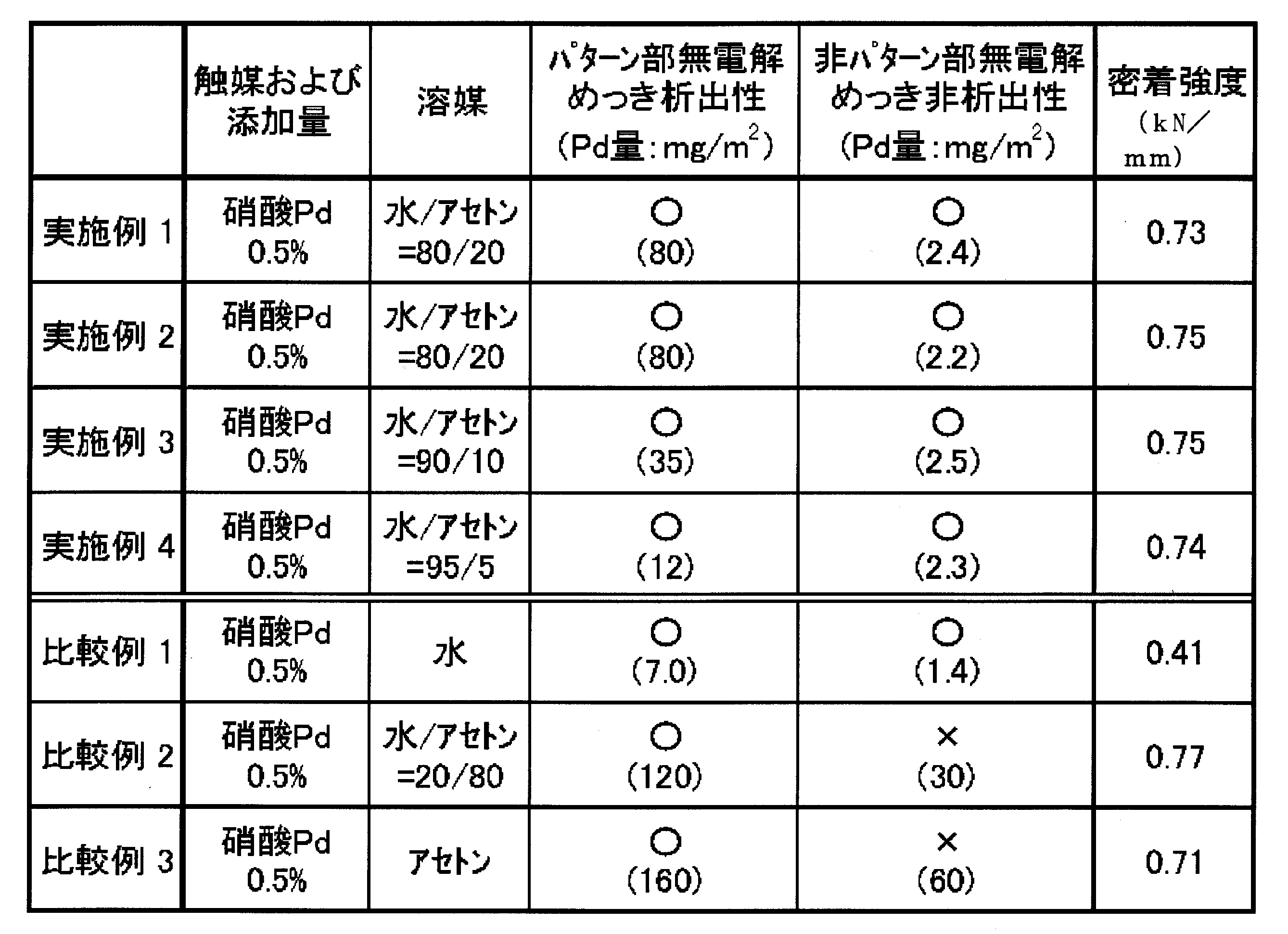
表1の結果より、本発明の触媒吸着方法により得られたパターン状金属層付き基板は、溶媒比率や基板表面の密着補助層を換えた場合でも、所望のめっき触媒受容性表面疎水性硬化物層に選択的且つ優先的にめっき触媒が吸着し、硬化物層が形成されていない基板表面ではめっき触媒の付着が抑制され、高精細の金属層パターンが形成されており、表面疎水性硬化物層と金属層との界面の平滑性、基板と金属層との密着性のいずれも良好であることがわかる。表1の非パターン部無電解めっき非析出性の評価として、Pd吸着量が5mg/m2以下の場合を○と表記し、5mg/m2を超える場合をxと表記した。
他方、比較例では、金属膜の密着性とパターン形成性とのいずれかが劣り、これらを両立し得ないことがわかる。
他方、比較例では、金属膜の密着性とパターン形成性とのいずれかが劣り、これらを両立し得ないことがわかる。
<めっき触媒液中の溶媒吸収量評価>
上記実施例1で用いためっき受容性硬化物層を有する基板について、実施例1、3及び4が、めっき触媒液の溶剤を変えたものであることから、これらの試料についてめっき液の溶媒吸収量を測定した。また、比較例1~3についても同様の評価を行った。
上記実施例1で用いためっき受容性硬化物層を有する基板について、実施例1、3及び4が、めっき触媒液の溶剤を変えたものであることから、これらの試料についてめっき液の溶媒吸収量を測定した。また、比較例1~3についても同様の評価を行った。
ここで、めっき触媒液における溶媒の吸収量は、基材表面の全面に実施例1で用いたのと同様の材料により厚み0.2mmの表面疎水性硬化物層を形成したサンプルと、厚み0.2mmの密着補助層1の3cm×3cmのサイズのサンプルを準備し、実施例1,3及び4で使用しためっき触媒液と同じ溶媒に浸漬を行い、重量変化によって吸収量を測定し、重量が24時間経過しても変化しない事を確認した時点で吸収量と定義した。表面付着成分はウエスで拭き取り、測定誤差を小さくするために、10枚の試験片の平均値を実施例のデータとした。
結果を下記表2に示す。
結果を下記表2に示す。
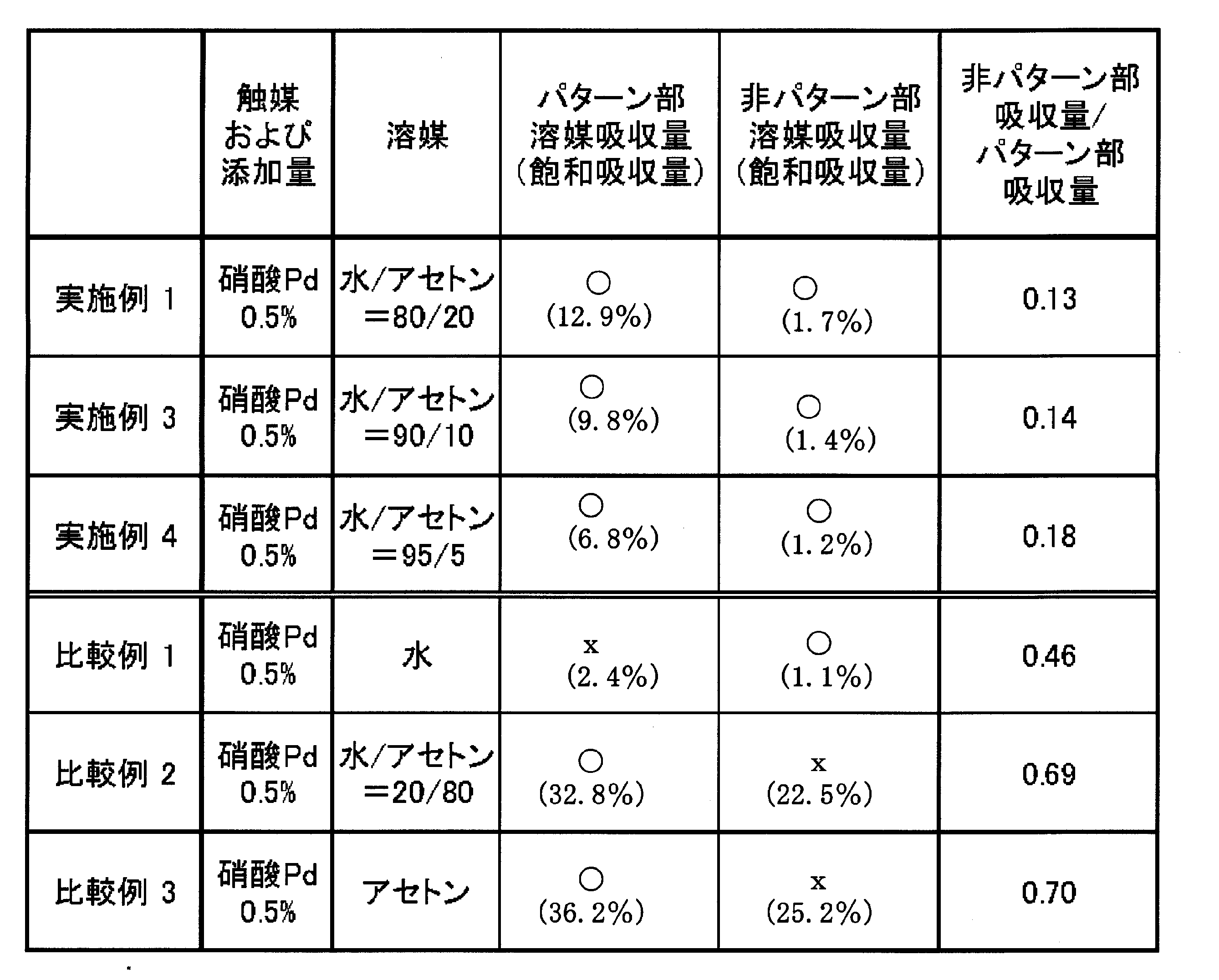
上記のように、本発明の実施例では、表面疎水性硬化物層と密着補助層1に対する溶媒の吸着量は本発明の範囲内であり、めっき触媒液の溶媒吸収もパターン状に選択的に行われている。この結果、及び、前記表1に記載の評価結果より、このような物性を満たす実施例では、選択的な金属パターンの形成性と硬化物層と金属膜との高い密着性を達成していることが裏付けられた。
他方、表面疎水性硬化物層の溶媒吸収量が低い比較例1や、溶媒吸収量に優れていても、表面疎水性硬化物層の未形成領域の溶媒吸収量も高い比較例2、3では、本発明の効果が得られず、溶媒の選択的且つ適切な吸収量の達成が本発明の効果に有効であることがわかる。
日本出願2007-338035と日本出願2008-108577の開示はその全体が参照により本明細書に取り込まれる。
本明細書に記載された全ての文献、特許出願、および技術規格は、個々の文献、特許出願、および技術規格が参照により取り込まれることが具体的かつ個々に記された場合と同程度に、本明細書中に参照により取り込まれる。
他方、表面疎水性硬化物層の溶媒吸収量が低い比較例1や、溶媒吸収量に優れていても、表面疎水性硬化物層の未形成領域の溶媒吸収量も高い比較例2、3では、本発明の効果が得られず、溶媒の選択的且つ適切な吸収量の達成が本発明の効果に有効であることがわかる。
日本出願2007-338035と日本出願2008-108577の開示はその全体が参照により本明細書に取り込まれる。
本明細書に記載された全ての文献、特許出願、および技術規格は、個々の文献、特許出願、および技術規格が参照により取り込まれることが具体的かつ個々に記された場合と同程度に、本明細書中に参照により取り込まれる。
Claims (15)
- めっき触媒又はその前駆体と相互作用を形成する官能基と、重合性基とを有する化合物を含有し、光硬化によって下記条件1及び条件2を満たす表面疎水性硬化物を形成する光硬化性組成物を基板上に塗布する工程、
パターン状に露光し、該光硬化性組成物を硬化させて露光領域に表面疎水性硬化物層を形成する工程、
現像液により該光硬化性組成物の未硬化物を除去してパターン状の表面疎水性硬化物層を形成する工程、
及び、該パターン状の表面疎水性硬化物層を形成した基板に、めっき触媒又はその前駆体と有機溶剤とを含有する水性めっき触媒液を接触させる工程、を含み、
パラジウムを含む試験液を該パターン状の表面疎水性硬化物層を形成した基板に接触させたときの、表面疎水性硬化物層形成領域におけるパラジウムの吸着量をAmg/m2、表面疎水性硬化物層未形成領域におけるパラジウムの吸着量をBmg/m2としたとき、以下の関係式(A)、(B)を満たす触媒吸着方法。
式(A):10mg/m2≦A≦150mg/m2
式(B):0mg/m2≦B≦5mg/m2
条件1:25℃-50%相対湿度環境下における飽和吸水率が0.01~5質量%
条件2:25℃-95%相対湿度環境下における飽和吸水率が0.05~10質量% - 前記めっき触媒又はその前駆体がパラジウム、銀、銅、ニッケル、アルミニウム、鉄、若しくはコバルト、又はこれらの前駆体である請求項1に記載の触媒吸着方法。
- めっき触媒又はその前駆体と相互作用を形成する官能基と、重合性基とを有する化合物を含有し、光硬化によって下記条件1及び条件2を満たす表面疎水性硬化物を形成する光硬化性組成物を基板上に塗布する工程、
パターン状に露光し、該光硬化性組成物を硬化させて露光領域に表面疎水性硬化物層を形成する工程、
現像液により該感光性樹脂組成物の未硬化物を除去してパターン状の表面疎水性硬化物層を形成する工程、
及び、該パターン状の表面疎水性硬化物層を形成した基板に、めっき触媒又はその前駆体と有機溶剤とを含有する水性めっき触媒液を接触させる工程、を含み、
パラジウムを含む試験液の溶媒が、表面疎水性硬化物層の質量に対して3%以上50%以下の吸収率を有し、且つ、表面疎水性硬化物層未形成領域の質量に対して0.1%以上2.0%未満の吸収率を有している触媒吸着方法。
条件1:25℃-50%相対湿度環境下における飽和吸水率が0.01~5質量%
条件2:25℃-95%相対湿度環境下における飽和吸水率が0.05~10質量% - 前記めっき触媒又はその前駆体がパラジウム、銀、銅、ニッケル、アルミニウム、鉄、若しくはコバルト、又はこれらの前駆体である請求項3に記載の触媒吸着方法。
- 前記パターン状の表面疎水性硬化物層を形成した基板に、めっき触媒又はその前駆体と有機溶剤とを含有する水性めっき触媒液を接触させる工程において、パラジウムをめっき触媒の表面疎水性硬化物層の質量に対する吸収率をC(質量%)、パラジウムをめっき触媒の表面疎水性硬化物層未形成領域の質量に対する吸収率をD(質量%)としたとき、以下の関係式(C)を満たす請求項3又は4に記載の触媒吸着方法。
式(C):0.002<(D/C)<0.67 - 前記光硬化性組成物を基板上に塗布する工程に先立ち、前記光硬化性組成物により形成される膜と相互作用を形成し得る活性点を発生させる活性種を含有する密着補助層を、基板上に形成する工程を有する請求項1から請求項5のいずれか1項に記載の触媒吸着方法。
- 前記有機溶剤が水溶性であり、且つ、水性めっき触媒液全量に対する含有量が0.5~40質量%である請求項1から請求項6のいずれか1項に記載の触媒吸着方法。
- 前記重合性基とめっき触媒又はその前駆体と相互作用を形成する官能基を有する化合物が、重合性基とめっき触媒又はその前駆体と相互作用を形成する官能基を有するポリマーであることを特徴とする請求項1から請求項7のいずれか1項に記載の触媒吸着方法
- めっき触媒又はその前駆体と相互作用を形成する官能基が、含窒素官能基、含酸素官能基、または含硫黄官能基であることを特徴とする請求項1から請求項8のいずれか1項に記載の触媒吸着方法。
- めっき触媒又はその前駆体と相互作用を形成する官能基が、エーテル基またはシアノ基であることを特徴とする請求項1から請求項8のいずれか1項に記載の触媒吸着方法。
- めっき触媒又はその前駆体と相互作用を形成する官能基が、シアノ基であることを特徴とする請求項1から請求項8のいずれか1項に記載の触媒吸着方法。
- 前記重合性基とめっき触媒又はその前駆体と相互作用を形成する官能基を有するポリマーが、下記式(1)で表されるユニット及び下記式(2)で表されるユニットを含む共重合体であることを特徴とする請求項8に記載の触媒吸着方法。
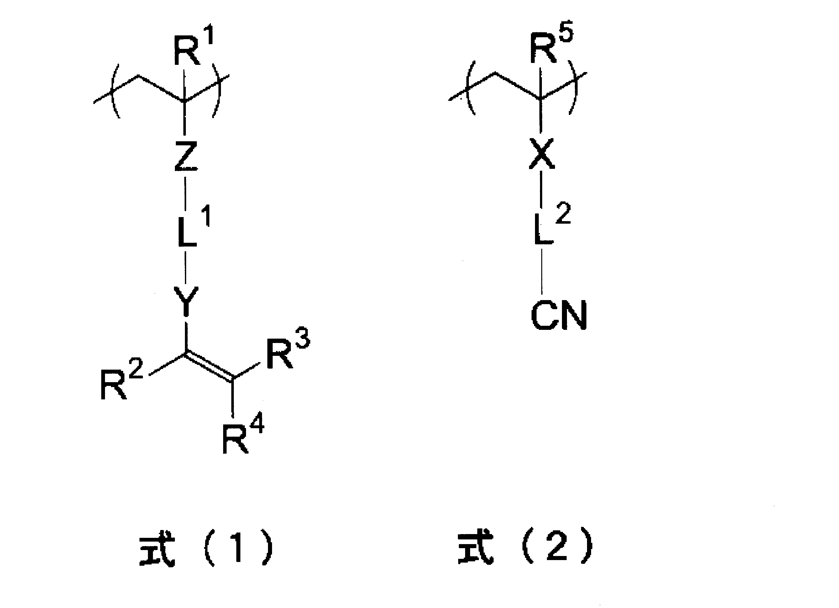
- 請求項1から請求項12のいずれか1項に記載の触媒吸着方法により得られた、パターン状の表面疎水性硬化物層にめっき触媒又はその前駆体が吸着してなる基板を、無電解めっきする工程を含む、パターン状金属層付き基板の製造方法。
- さらに、電気めっきを行う請求項13に記載のパターン状金属層付き基板の製造方法。
- 請求項1から請求項12のいずれか1項に記載の触媒吸着方法に用いられ、めっき触媒と水溶性有機溶剤とを含有することを特徴とする水性めっき触媒液。
Priority Applications (3)
| Application Number | Priority Date | Filing Date | Title |
|---|---|---|---|
| US12/810,806 US20100279012A1 (en) | 2007-12-27 | 2008-12-05 | Method for adsorbing plating catalyst, method for preparing substrate provided with metal layer, and plating catalyst solution used in the same |
| EP08868090.5A EP2236647B1 (en) | 2007-12-27 | 2008-12-05 | Process for adsorbing plating catalysts, process for production of substrates provided with metal layers and plating catalyst containing fluid for use in both processes |
| CN2008801230643A CN101910462B (zh) | 2007-12-27 | 2008-12-05 | 镀催化剂的吸附方法、覆有金属层的基板的制造方法 |
Applications Claiming Priority (4)
| Application Number | Priority Date | Filing Date | Title |
|---|---|---|---|
| JP2007-338035 | 2007-12-27 | ||
| JP2007338035 | 2007-12-27 | ||
| JP2008-108577 | 2008-04-18 | ||
| JP2008108577A JP2009174041A (ja) | 2007-12-27 | 2008-04-18 | めっき触媒吸着方法、金属層付き基板の製造方法及びそれらに用いるめっき触媒液 |
Publications (1)
| Publication Number | Publication Date |
|---|---|
| WO2009084371A1 true WO2009084371A1 (ja) | 2009-07-09 |
Family
ID=40824092
Family Applications (1)
| Application Number | Title | Priority Date | Filing Date |
|---|---|---|---|
| PCT/JP2008/072115 WO2009084371A1 (ja) | 2007-12-27 | 2008-12-05 | めっき触媒吸着方法、金属層付き基板の製造方法及びそれらに用いるめっき触媒液 |
Country Status (5)
| Country | Link |
|---|---|
| US (1) | US20100279012A1 (ja) |
| EP (1) | EP2236647B1 (ja) |
| JP (1) | JP2009174041A (ja) |
| CN (1) | CN101910462B (ja) |
| WO (1) | WO2009084371A1 (ja) |
Cited By (1)
| Publication number | Priority date | Publication date | Assignee | Title |
|---|---|---|---|---|
| WO2017170012A1 (ja) * | 2016-03-30 | 2017-10-05 | 富士フイルム株式会社 | 金属配線含有積層体の製造方法、金属配線含有積層体、被めっき層付き基板 |
Families Citing this family (12)
| Publication number | Priority date | Publication date | Assignee | Title |
|---|---|---|---|---|
| US9822088B2 (en) | 2011-03-30 | 2017-11-21 | The United States Of America As Represented By The Administrator Of Nasa | Anisotropic copoly(imide oxetane) coatings and articles of manufacture, copoly(imide oxetane)s containing pendant fluorocarbon moieties, oligomers and processes therefor |
| US9278374B2 (en) | 2012-06-08 | 2016-03-08 | The United States Of America As Represented By The Administrator Of The National Aeronautics And Space Administration | Modified surface having low adhesion properties to mitigate insect residue adhesion |
| JP5725073B2 (ja) * | 2012-10-30 | 2015-05-27 | 三菱電機株式会社 | 半導体素子の製造方法、半導体素子 |
| US9451707B2 (en) * | 2012-12-13 | 2016-09-20 | Dow Global Technologies Llc | Stabilized silver catalysts and methods |
| JP6318895B2 (ja) * | 2014-06-17 | 2018-05-09 | 日立化成株式会社 | 配線板及びその製造方法 |
| CN107637184B (zh) * | 2015-06-04 | 2020-07-17 | 住友电气工业株式会社 | 印刷线路板用基板和印刷线路板 |
| CN109126912B (zh) * | 2017-06-15 | 2021-02-02 | 上海微创医疗器械(集团)有限公司 | 生物芯片及其制备方法 |
| CN109134801B (zh) * | 2017-06-15 | 2021-01-12 | 狄超 | 一种用生产二甲氨基乙基丙烯酸酯的精馏残渣制备聚氨酯催化剂的方法 |
| CN109518171B (zh) * | 2018-12-24 | 2020-10-27 | 广州传福化学技术有限公司 | 一种化学镀镍液 |
| CN113084185B (zh) * | 2021-03-26 | 2022-05-20 | 华中科技大学 | 一种Pd1-CoSe2纳米带及其制备方法与应用 |
| CN113304738B (zh) * | 2021-04-28 | 2023-03-17 | 郑州师范学院 | 一种催化基板及其制备方法 |
| WO2023084961A1 (ja) * | 2021-11-10 | 2023-05-19 | 日産化学株式会社 | 薬液耐性保護膜 |
Citations (12)
| Publication number | Priority date | Publication date | Assignee | Title |
|---|---|---|---|---|
| JPS6392658A (ja) | 1986-10-07 | 1988-04-23 | Bio Material Yunibaasu:Kk | 高分子表面改質のための空気酸素溶存下におけるラジカル重合法 |
| JPH0685433A (ja) | 1992-09-01 | 1994-03-25 | Ibiden Co Ltd | プリント配線板の製造方法 |
| JPH09307216A (ja) | 1996-05-13 | 1997-11-28 | Ngk Spark Plug Co Ltd | 配線基板の製造方法及び配線基板 |
| JPH10296895A (ja) | 1997-04-23 | 1998-11-10 | Kawamura Inst Of Chem Res | 表面親水性成形物、その製造方法、印刷原版及び画像形成方法 |
| JPH11119413A (ja) | 1997-10-09 | 1999-04-30 | Mitsubishi Chemical Corp | ダイレクト感光性平版印刷版 |
| JPH11350149A (ja) | 1998-06-15 | 1999-12-21 | Okuno Chem Ind Co Ltd | 無電解部分めっき方法 |
| JP2003166068A (ja) | 2001-09-21 | 2003-06-13 | Toshiba Corp | 複合部材の製造方法及び複合部材形成用多孔質基材並びに複合部材形成用感光性化合物及び複合部材形成用組成物 |
| JP2004353027A (ja) * | 2003-05-28 | 2004-12-16 | Taiyo Ink Mfg Ltd | 無電解めっきパターン形成用組成物、無電解めっきパターン及びその形成方法 |
| JP2005281350A (ja) | 2004-03-26 | 2005-10-13 | Fuji Photo Film Co Ltd | パターン形成方法、グラフトパターン材料、導電性パターン形成方法、及び導電性パターン材料 |
| JP2005307140A (ja) | 2004-03-24 | 2005-11-04 | Fuji Photo Film Co Ltd | 表面グラフト形成方法、導電性膜の形成方法、金属パターン形成方法、多層配線板の形成方法、表面グラフト材料、及び導電性材料 |
| JP2007144820A (ja) | 2005-11-28 | 2007-06-14 | Fujifilm Corp | プリント配線板用積層体、及び、それを用いたプリント配線板の作製方法 |
| JP2007154369A (ja) | 2005-12-06 | 2007-06-21 | Hokuetsu Paper Mills Ltd | 耐油紙及びその製造方法 |
Family Cites Families (7)
| Publication number | Priority date | Publication date | Assignee | Title |
|---|---|---|---|---|
| US4162337A (en) * | 1977-11-14 | 1979-07-24 | Bell Telephone Laboratories, Incorporated | Process for fabricating III-V semiconducting devices with electroless gold plating |
| KR100560268B1 (ko) * | 2002-04-23 | 2006-03-10 | 가부시키 가이샤 닛코 마테리알즈 | 무전해 도금방법 및 금속도금층이 형성된 반도체 웨이퍼 |
| JP4684632B2 (ja) * | 2003-11-27 | 2011-05-18 | 富士フイルム株式会社 | 金属パターン形成方法、金属パターン及びプリント配線板 |
| EP1581031B1 (en) * | 2004-03-25 | 2010-10-06 | FUJIFILM Corporation | Methods of forming a pattern and a conductive pattern |
| JP2005347423A (ja) * | 2004-06-01 | 2005-12-15 | Fuji Photo Film Co Ltd | 金属パターン形成方法、及び導電性パターン材料 |
| DE602005024595D1 (de) * | 2004-08-26 | 2010-12-16 | Fujifilm Corp | Verfahren zur herstellung eines elektrisch leitfähigen strukturmaterials |
| JP2007270216A (ja) * | 2006-03-30 | 2007-10-18 | Fujifilm Corp | 金属膜形成方法、それを用いた金属膜、金属膜形成用基板、金属パターン形成方法、及びそれを用いた金属パターン、金属パターン形成用基板、ポリマー前駆体層形成用塗布液組成物 |
-
2008
- 2008-04-18 JP JP2008108577A patent/JP2009174041A/ja not_active Abandoned
- 2008-12-05 WO PCT/JP2008/072115 patent/WO2009084371A1/ja active Application Filing
- 2008-12-05 US US12/810,806 patent/US20100279012A1/en not_active Abandoned
- 2008-12-05 EP EP08868090.5A patent/EP2236647B1/en active Active
- 2008-12-05 CN CN2008801230643A patent/CN101910462B/zh active Active
Patent Citations (12)
| Publication number | Priority date | Publication date | Assignee | Title |
|---|---|---|---|---|
| JPS6392658A (ja) | 1986-10-07 | 1988-04-23 | Bio Material Yunibaasu:Kk | 高分子表面改質のための空気酸素溶存下におけるラジカル重合法 |
| JPH0685433A (ja) | 1992-09-01 | 1994-03-25 | Ibiden Co Ltd | プリント配線板の製造方法 |
| JPH09307216A (ja) | 1996-05-13 | 1997-11-28 | Ngk Spark Plug Co Ltd | 配線基板の製造方法及び配線基板 |
| JPH10296895A (ja) | 1997-04-23 | 1998-11-10 | Kawamura Inst Of Chem Res | 表面親水性成形物、その製造方法、印刷原版及び画像形成方法 |
| JPH11119413A (ja) | 1997-10-09 | 1999-04-30 | Mitsubishi Chemical Corp | ダイレクト感光性平版印刷版 |
| JPH11350149A (ja) | 1998-06-15 | 1999-12-21 | Okuno Chem Ind Co Ltd | 無電解部分めっき方法 |
| JP2003166068A (ja) | 2001-09-21 | 2003-06-13 | Toshiba Corp | 複合部材の製造方法及び複合部材形成用多孔質基材並びに複合部材形成用感光性化合物及び複合部材形成用組成物 |
| JP2004353027A (ja) * | 2003-05-28 | 2004-12-16 | Taiyo Ink Mfg Ltd | 無電解めっきパターン形成用組成物、無電解めっきパターン及びその形成方法 |
| JP2005307140A (ja) | 2004-03-24 | 2005-11-04 | Fuji Photo Film Co Ltd | 表面グラフト形成方法、導電性膜の形成方法、金属パターン形成方法、多層配線板の形成方法、表面グラフト材料、及び導電性材料 |
| JP2005281350A (ja) | 2004-03-26 | 2005-10-13 | Fuji Photo Film Co Ltd | パターン形成方法、グラフトパターン材料、導電性パターン形成方法、及び導電性パターン材料 |
| JP2007144820A (ja) | 2005-11-28 | 2007-06-14 | Fujifilm Corp | プリント配線板用積層体、及び、それを用いたプリント配線板の作製方法 |
| JP2007154369A (ja) | 2005-12-06 | 2007-06-21 | Hokuetsu Paper Mills Ltd | 耐油紙及びその製造方法 |
Cited By (2)
| Publication number | Priority date | Publication date | Assignee | Title |
|---|---|---|---|---|
| WO2017170012A1 (ja) * | 2016-03-30 | 2017-10-05 | 富士フイルム株式会社 | 金属配線含有積層体の製造方法、金属配線含有積層体、被めっき層付き基板 |
| JPWO2017170012A1 (ja) * | 2016-03-30 | 2018-08-23 | 富士フイルム株式会社 | 金属配線含有積層体の製造方法、金属配線含有積層体、被めっき層付き基板 |
Also Published As
| Publication number | Publication date |
|---|---|
| CN101910462A (zh) | 2010-12-08 |
| EP2236647A4 (en) | 2016-12-14 |
| EP2236647A1 (en) | 2010-10-06 |
| US20100279012A1 (en) | 2010-11-04 |
| CN101910462B (zh) | 2012-09-26 |
| EP2236647B1 (en) | 2018-02-21 |
| JP2009174041A (ja) | 2009-08-06 |
Similar Documents
| Publication | Publication Date | Title |
|---|---|---|
| EP2236647B1 (en) | Process for adsorbing plating catalysts, process for production of substrates provided with metal layers and plating catalyst containing fluid for use in both processes | |
| JP5448524B2 (ja) | めっき用積層フィルム、表面金属膜材料の作製方法及び表面金属膜材料 | |
| US8084564B2 (en) | Metal-film-coated material and process for producing the same, metallic-pattern-bearing material and process for producing the same, composition for polymer layer formation, nitrile group-containing polymer and method of synthesizing the same, composition containing nitrile group-containing polymer, and laminate | |
| JP5258283B2 (ja) | 金属箔付基板、及びその作製方法 | |
| JP5419441B2 (ja) | 多層配線基板の形成方法 | |
| JP5334777B2 (ja) | 被めっき層形成用組成物、金属パターン材料の作製方法、及び、新規ポリマー | |
| JP2009164575A (ja) | 表面金属膜材料の作製方法、表面金属膜材料、金属パターン材料の作製方法、金属パターン材料、及びポリマー層形成用組成物 | |
| JP5258489B2 (ja) | 金属膜形成方法 | |
| JP2010185128A (ja) | めっき用感光性樹脂組成物、積層体、それを用いた表面金属膜材料の作製方法、表面金属膜材料、金属パターン材料の作製方法、金属パターン材料、及び配線基板 | |
| JP2008135685A (ja) | 配線基板の製造方法及び配線基板、並びに、多層配線基板の製造方法及び多層配線基板 | |
| JP2010254971A (ja) | 新規共重合ポリマー、新規共重合ポリマーを含有する組成物、積層体、表面金属膜材料の作製方法、表面金属膜材料、金属パターン材料の作製方法、及び金属パターン材料 | |
| US20100272902A1 (en) | Plating method, method for forming metal thin film, and plating catalyst liquid | |
| JP2010077322A (ja) | 被めっき層形成用組成物、金属パターン材料の作製方法及びそれにより得られた金属パターン材料、表面金属膜材料の作製方法及びそれにより得られた表面金属膜材料 | |
| JP2009161857A (ja) | めっき用感光性樹脂組成物、及び、それを用いた金属層付き基板の製造方法 | |
| JP5106025B2 (ja) | 表面金属膜材料の作製方法、表面金属膜材料、金属パターン材料の作製方法、金属パターン材料、及びポリマー層形成用組成物 | |
| JP2010077509A (ja) | めっき方法、金属薄膜形成方法 | |
| JP2009006698A (ja) | 両面金属膜付きフィルムの製造方法、及び両面金属膜付きフィルム | |
| JP2009256777A (ja) | 表面金属膜材料の作製方法及びそれにより得られる表面金属膜材料 | |
| JP2009158855A (ja) | プリント配線板の製造方法及びそれに用いる洗浄液 | |
| JP2011111602A (ja) | 絶縁性樹脂、絶縁性樹脂層形成用組成物、積層体、表面金属膜材料の作製方法、金属パターン材料の作製方法、配線基板の作製方法、電子部品、及び、半導体素子 | |
| WO2012032905A1 (ja) | 被めっき層形成用組成物、金属パターン材料の製造方法、および、新規ポリマー |
Legal Events
| Date | Code | Title | Description |
|---|---|---|---|
| WWE | Wipo information: entry into national phase |
Ref document number: 200880123064.3 Country of ref document: CN |
|
| 121 | Ep: the epo has been informed by wipo that ep was designated in this application |
Ref document number: 08868090 Country of ref document: EP Kind code of ref document: A1 |
|
| WWE | Wipo information: entry into national phase |
Ref document number: 12810806 Country of ref document: US |
|
| NENP | Non-entry into the national phase |
Ref country code: DE |
|
| WWE | Wipo information: entry into national phase |
Ref document number: 2008868090 Country of ref document: EP |