WO2004074014A1 - タイヤ/ホイール組立体 - Google Patents
タイヤ/ホイール組立体 Download PDFInfo
- Publication number
- WO2004074014A1 WO2004074014A1 PCT/JP2004/001911 JP2004001911W WO2004074014A1 WO 2004074014 A1 WO2004074014 A1 WO 2004074014A1 JP 2004001911 W JP2004001911 W JP 2004001911W WO 2004074014 A1 WO2004074014 A1 WO 2004074014A1
- Authority
- WO
- WIPO (PCT)
- Prior art keywords
- tire
- wheel
- wheel assembly
- layer
- belt layer
- Prior art date
- Legal status (The legal status is an assumption and is not a legal conclusion. Google has not performed a legal analysis and makes no representation as to the accuracy of the status listed.)
- Ceased
Links
Classifications
-
- B—PERFORMING OPERATIONS; TRANSPORTING
- B60—VEHICLES IN GENERAL
- B60B—VEHICLE WHEELS; CASTORS; AXLES FOR WHEELS OR CASTORS; INCREASING WHEEL ADHESION
- B60B21/00—Rims
- B60B21/02—Rims characterised by transverse section
- B60B21/028—Rims characterised by transverse section the shape of hump
-
- B—PERFORMING OPERATIONS; TRANSPORTING
- B60—VEHICLES IN GENERAL
- B60B—VEHICLE WHEELS; CASTORS; AXLES FOR WHEELS OR CASTORS; INCREASING WHEEL ADHESION
- B60B3/00—Disc wheels, i.e. wheels with load-supporting disc body
-
- B—PERFORMING OPERATIONS; TRANSPORTING
- B60—VEHICLES IN GENERAL
- B60C—VEHICLE TYRES; TYRE INFLATION; TYRE CHANGING; CONNECTING VALVES TO INFLATABLE ELASTIC BODIES IN GENERAL; DEVICES OR ARRANGEMENTS RELATED TO TYRES
- B60C9/00—Reinforcements or ply arrangement of pneumatic tyres
- B60C9/18—Structure or arrangement of belts or breakers, crown-reinforcing or cushioning layers
- B60C9/20—Structure or arrangement of belts or breakers, crown-reinforcing or cushioning layers built-up from rubberised plies each having all cords arranged substantially parallel
- B60C9/22—Structure or arrangement of belts or breakers, crown-reinforcing or cushioning layers built-up from rubberised plies each having all cords arranged substantially parallel the plies being arranged with all cords disposed along the circumference of the tyre
-
- Y—GENERAL TAGGING OF NEW TECHNOLOGICAL DEVELOPMENTS; GENERAL TAGGING OF CROSS-SECTIONAL TECHNOLOGIES SPANNING OVER SEVERAL SECTIONS OF THE IPC; TECHNICAL SUBJECTS COVERED BY FORMER USPC CROSS-REFERENCE ART COLLECTIONS [XRACs] AND DIGESTS
- Y10—TECHNICAL SUBJECTS COVERED BY FORMER USPC
- Y10T—TECHNICAL SUBJECTS COVERED BY FORMER US CLASSIFICATION
- Y10T152/00—Resilient tires and wheels
- Y10T152/10—Tires, resilient
- Y10T152/10495—Pneumatic tire or inner tube
- Y10T152/10765—Characterized by belt or breaker structure
-
- Y—GENERAL TAGGING OF NEW TECHNOLOGICAL DEVELOPMENTS; GENERAL TAGGING OF CROSS-SECTIONAL TECHNOLOGIES SPANNING OVER SEVERAL SECTIONS OF THE IPC; TECHNICAL SUBJECTS COVERED BY FORMER USPC CROSS-REFERENCE ART COLLECTIONS [XRACs] AND DIGESTS
- Y10—TECHNICAL SUBJECTS COVERED BY FORMER USPC
- Y10T—TECHNICAL SUBJECTS COVERED BY FORMER US CLASSIFICATION
- Y10T152/00—Resilient tires and wheels
- Y10T152/10—Tires, resilient
- Y10T152/10495—Pneumatic tire or inner tube
- Y10T152/10765—Characterized by belt or breaker structure
- Y10T152/10783—Reinforcing plies made up from wound narrow ribbons
-
- Y—GENERAL TAGGING OF NEW TECHNOLOGICAL DEVELOPMENTS; GENERAL TAGGING OF CROSS-SECTIONAL TECHNOLOGIES SPANNING OVER SEVERAL SECTIONS OF THE IPC; TECHNICAL SUBJECTS COVERED BY FORMER USPC CROSS-REFERENCE ART COLLECTIONS [XRACs] AND DIGESTS
- Y10—TECHNICAL SUBJECTS COVERED BY FORMER USPC
- Y10T—TECHNICAL SUBJECTS COVERED BY FORMER US CLASSIFICATION
- Y10T152/00—Resilient tires and wheels
- Y10T152/10—Tires, resilient
- Y10T152/10495—Pneumatic tire or inner tube
- Y10T152/10765—Characterized by belt or breaker structure
- Y10T152/1081—Breaker or belt characterized by the chemical composition or physical properties of elastomer or the like
Definitions
- the present invention relates to a tire / wheel assembly, and more particularly, to a tire / wheel assembly capable of reducing a load noise while using a light metal wheel.
- Reducing the unsprung mass of a passenger car has the effect of improving ride comfort and reducing fuel consumption.
- the most common means for reducing the weight of panel lower mass is to use a light metal wheel for the wheel, as disclosed in Japanese Patent Application Laid-Open No. 2002-27411. You can do it.
- An object of the present invention is to provide a tire / wheel assembly capable of reducing road noise while reducing the weight under a panel by a light metal wheel.
- the tire / wheel assembly of the present invention that achieves the above object has a stiffness index ⁇
- the wheel stiffness When light metal wheels are lightened to a stiffness index less than 65 (1 / rad), the wheel stiffness also decreases. The natural frequency of the wheel also decreases due to the decrease in the rigidity of the wheel. Get closer. Therefore, the light metal wheel resonates with vibration near 300 Hz generated by the running pneumatic tire, and the vibration generated by this resonance propagates through the axle into the vehicle interior, and By generating resonance, road noise around 300 Hz is generated.
- the rigidity of a part of the shoulder is increased by arranging the reinforcing layer at the end of the belt layer of the pneumatic tire mounted on the light metal wheel.
- the natural frequency of the shoulder partial region increases, and the light metal wheel can be shifted from the natural frequency. Therefore, the light metal wheel does not resonate in response to the vibration of the pneumatic tire, and the vibration near 300 Hz does not propagate to the vehicle interior, so that road noise due to the resonance of the vehicle interior can be eliminated.
- FIG. 1 is a meridian half sectional view showing a main part of a tire / wheel assembly according to an embodiment of the present invention.
- FIG. 2 is a meridian half sectional view showing a main part of a tire / wheel assembly according to another embodiment of the present invention.
- FIG. 3 is an explanatory diagram illustrating a method of measuring the wheel rigidity index ⁇ .
- FIG. 4 is an explanatory view of a durability test apparatus for a single-piece assembly, a best mode for carrying out the invention.
- the tire / wheel assembly of the present invention uses a light metal wheel for the wheel.
- the light metal wheel has a rigidity index ⁇ of 35 to 65 (1 / rad), preferably 40 to 50 (1 / rad). is there.
- the wheel stiffness has been significantly reduced so that the stiffness index a is in the range of 35 to 65 (1 / rad), so that the ride comfort is significantly improved compared to conventional steel wheels, and Fuel efficiency is also reduced. If the wheel stiffness index ⁇ is greater than 65 (1 / rad), the improvement in ride comfort as described above cannot be obtained. If the stiffness index ⁇ of the wheel is smaller than 35 (1 / rad), the durability of the wheel decreases and it becomes difficult to put the wheel into practical use.
- the light metal constituting the wheel is not particularly limited as long as it satisfies the range of the rigidity index ⁇ .
- aluminum or an alloy thereof is preferably used. 7
- light metals other than luminium, magnesium, titanium, or alloys thereof can be used.
- the rigidity index ⁇ defining the rigidity of the wheel in the present invention refers to a characteristic value measured as follows.
- the inner flange portion 1f of the light metal wheel 1 is fixed to the fixing seat 30 with the fastener 31 and the load arm 32 is mounted on the disk 1d of the wheel 1 Fixed so that they match. Then, a weight F (kN) is applied to the rear end of the load arm 32 by suspending the weight 33 at a distance S from the disk surface, and the displacement ⁇ generated at that time is obtained.
- the inner flange portion 1f means the flange portion facing the vehicle when the wheel is mounted on the vehicle.
- the force F (kN) is the maximum value (according to the rules of the Japan Automobile Tire Association) of the load corresponding to the maximum load capacity of the passenger car tire applied to the wheel. However, when targeting a limited number of vehicles, the maximum value of the stationary wheel reaction forces of those vehicles is used.
- the applied moment (kN. M) is given by F x S, and the displacement angle (r a d) is given by 5 / S.
- the light metal material of the wheel is an alloy of alloy No. 5000 specified in JISH400 "Aluminum and aluminum alloy plate and strip", and the content of magnesium If it is less than 3%, it shall be 1.8, and if it is a forged aluminum alloy, it shall be 1.0.
- r (m) is the maximum value of the static load radius of the tire for passenger cars applied to the wheel (according to the regulations of the Japan Automobile Tire Association Standard). However, in the case of limited use, it shall be the maximum value of the static load radius of the tires for passenger cars specified for those vehicles.
- D (m) is the distance between the wheel mounting surface of the wheel and the rim center line.
- a pneumatic tire mounted on the tire / wheel assembly of the present invention For this, a carcass layer having a reinforcing layer disposed at the end of a belt layer provided along the tire circumferential direction on the outer periphery is used.
- the rigidity of a part of the shoulder is increased by arranging the reinforcing layer at the end of the belt layer, and the natural frequency of the tire is increased due to the increase in the rigidity. Has also increased.
- the light metal wheel has reduced rigidity due to weight reduction, and as a result, the natural frequency of the light metal wheel is usually higher than the natural frequency of a pneumatically driven structure (around 300 Hz). ) Is approaching.
- the pneumatic tire has a general normal structure, road noise at a frequency of around 300 Hz is generated in the vehicle cabin during driving.
- the pneumatic tire applied in the present invention is shifted from the natural frequency of the light metal wheel because the natural frequency is higher than that of the tire having the normal structure as described above. Therefore, the light metal wheel does not resonate with the tire vibration and does not generate road noise near the frequency of 300 Hz in the vehicle interior.
- the reinforcing layer used for the pneumatic tire may be any one of the inside, outside, and between layers of the belt layer as long as it is disposed at the end of the belt layer. However, it is preferable to arrange it inside the belt layer so as to be sandwiched between the belt and the force layer.
- the reinforcing layer need not overlap the entire width of the belt layer, and may partially extend to the outside of the maximum width belt layer (the inner diameter side belt layer). It is preferable to extend from the end of the belt layer having the maximum width as a starting point, within a range of 5 mm inward from the starting point and 1 O mm outward from the starting point.
- the structure of the reinforcing layer is not particularly limited, but preferably includes a reinforcing cord and a coat rubber covering the reinforcing cord.
- the reinforcing cord cords such as nylon fiber, polyester fiber, polyvinyl alcohol fiber, and aramide fiber can be used. Of these, especially high ammunition Aramid fiber cords with a high modulus are preferred.
- the coated rubber preferably has a high elastic modulus, and particularly preferably has a tan ⁇ in the range of 0.15 to 0.25.
- tan 5 refers to a value measured at a temperature of 60 ° (: initial strain of 10%, amplitude of ⁇ 2%, and frequency of 20 Hz).
- the wrapping angle of the reinforcing cord may be arbitrary.However, in the case of low elastic modulus cords such as nylon, polyester and polyvinyl alcohol, the cord can be spirally wound at an angle of approximately 0 ° to the tire circumferential direction. preferable. Further, in the case of the high elastic modulus cord, it is preferable that the cord is spirally wound in a range of more than 0 ° and 15 ° or less with respect to the tire circumferential direction.
- FIG. 1 is a meridian sectional view showing a main part of a tire / wheel assembly (wheel) according to an embodiment of the present invention.
- the tire / wheel assembly is configured by mounting a pneumatic tire on the rim 1 r of the wheel 1.
- the wheel 1 is made of a light metal such as an aluminum alloy, has a rigidity index ⁇ in the range of 35 to 65 (1 / rad), and has a significantly reduced weight.
- the low rigidity of the wheel 1 greatly improves ride comfort.
- the pneumatic tire 2 has a carcass layer 3 in which force cascodes are arranged at a cord angle of about 90 ° with respect to the tire circumferential direction.
- the force layer 3 extends from the tread 4 to the bead portions 6 and 6 via the right and left side wall portions 5 and 5, and both ends are turned around the bead cores 7 and 7 from the inside of the evening to the outside. It is formed to be.
- two belt layers 8 made of a steel code are arranged so that the cords cross each other between the layers.
- Reinforcing layers 9 are provided at both ends of the belt layer 8 so as to be sandwiched between the belt layer 8 and the force layer 4.
- the rigidity of a part of the shoulder is increased, and the natural frequency is increased by the rigidity of the part of the shoulder.
- the natural frequency of the pneumatic tire is largely out of the natural frequency of the light metal wheel 1, and the light metal wheel 1 does not resonate with the vibration generated by the pneumatic tire 2 picking up from the road surface. Therefore, the vibration is not transmitted to the passenger compartment via the wheel 1 and the axle, and the road noise around 300 Hz is not generated in the passenger compartment.
- the reinforcing layer 9 is arranged inside the innermost inner side of the belt layer 8 so as to be sandwiched between the carcass layer 3 and the reinforcing layer 9 as in the embodiment of FIG. Alternatively, it may be arranged on the outer peripheral side of the end of the belt layer 8.
- two c may be inserted between the belt layer 8 is specifically described below of the present invention through examples, the following examples are for example shown It is for illustration purposes only and should not be used to limit the invention.
- the tire size is 195/60 R15
- the carcass layer is made of polyester code
- the belt layer is made of steel cord.
- the outer periphery of both ends of the belt layer is as shown in Fig. 2.
- a pneumatic tire ⁇ in which a woven fiber cord is spirally wound at approximately 0 ° in the circumferential direction of the tire and provided with a reinforcing layer coated with a coat rubber having a ta ⁇ of 0.18.
- a pneumatic tire B with no installation was manufactured.
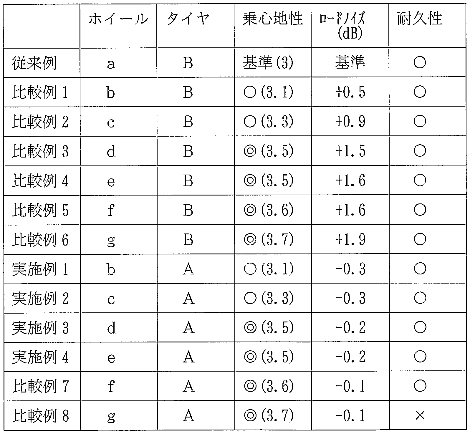
- test wheels (tire / wheel assembly) are filled with air pressure of 200 kPa-Displacement 2.5 Attached to a passenger car equipped with a 2.5-liter engine, and one test driver 5
- the ride comfort on a test run of the 5 km test course was evaluated by feeling.
- the evaluation points were set as a standard with three points in the conventional example, and expressed as a difference from this standard.
- a load W 13.7 kN is applied to the axle 41, and the tire / wheel assembly is pressed against the drive drum 40, and the drive drum 4 is pressed.
- the durability was evaluated based on whether or not wheel breakage occurred during that time.
- Example 5 In the tire / wheel assembly of Example 3, except that the position of the reinforcing layer of the nylon fiber cord was changed to the pneumatic tire C in which the position was changed between the belt layer on the inner diameter side and the carcass layer as shown in FIG. Tie with the same configuration as in Example 3 (Example 5).
- Example 7 Similarly, in the tire / wheel assembly of Example 3, except that the nylon fiber cord of the reinforcing layer was changed to an aramide fiber cord, and the coat rubber was changed to a pneumatic tire D whose tan 5 was changed to 0.15 rubber. Is a tire / wheel assembly having the same configuration as in Example 3 (Example 6). The nylon fiber cord of the reinforcing layer is changed to an aramide fiber cord, and the coated rubber is pneumatic with a tan 5 of 0.25. A tire / wheel assembly (Example 7) having the same configuration as that of Example 3 except that the tire E was used was manufactured.
- Table 3 shows the results of measuring ride comfort, road noise, and durability of these three types of tire / wheel assemblies using the same measurement method as described above.
Landscapes
- Engineering & Computer Science (AREA)
- Mechanical Engineering (AREA)
- Tires In General (AREA)
Abstract
Description


Claims
Priority Applications (4)
| Application Number | Priority Date | Filing Date | Title |
|---|---|---|---|
| DE112004000289.3T DE112004000289B4 (de) | 2003-02-24 | 2004-02-19 | Reifen-/Rad-Anordnungskörper |
| US10/542,034 US7614437B2 (en) | 2003-02-24 | 2004-02-19 | Tire/wheel assembly body |
| JP2005500659A JP4353534B2 (ja) | 2003-02-24 | 2004-02-19 | タイヤ/ホイール組立体 |
| CN200480005027.4A CN1753795B (zh) | 2003-02-24 | 2004-02-19 | 轮胎/车轮组装体 |
Applications Claiming Priority (2)
| Application Number | Priority Date | Filing Date | Title |
|---|---|---|---|
| JP2003046288 | 2003-02-24 | ||
| JP2003-046288 | 2003-02-24 |
Publications (1)
| Publication Number | Publication Date |
|---|---|
| WO2004074014A1 true WO2004074014A1 (ja) | 2004-09-02 |
Family
ID=32905546
Family Applications (1)
| Application Number | Title | Priority Date | Filing Date |
|---|---|---|---|
| PCT/JP2004/001911 Ceased WO2004074014A1 (ja) | 2003-02-24 | 2004-02-19 | タイヤ/ホイール組立体 |
Country Status (5)
| Country | Link |
|---|---|
| US (1) | US7614437B2 (ja) |
| JP (1) | JP4353534B2 (ja) |
| CN (1) | CN1753795B (ja) |
| DE (1) | DE112004000289B4 (ja) |
| WO (1) | WO2004074014A1 (ja) |
Families Citing this family (4)
| Publication number | Priority date | Publication date | Assignee | Title |
|---|---|---|---|---|
| JP4188029B2 (ja) * | 2002-08-23 | 2008-11-26 | 横浜ゴム株式会社 | タイヤ用ホイール |
| JP5283694B2 (ja) * | 2007-06-22 | 2013-09-04 | ピレリ・タイヤ・ソチエタ・ペル・アツィオーニ | 重荷重車両用タイヤ |
| CN102029862A (zh) * | 2010-12-02 | 2011-04-27 | 中橡集团曙光橡胶工业研究设计院 | 一种子午线航空轮胎缠绕包边带束层结构 |
| JP6928494B2 (ja) * | 2017-06-19 | 2021-09-01 | 株式会社ブリヂストン | 空気入りタイヤ |
Citations (7)
| Publication number | Priority date | Publication date | Assignee | Title |
|---|---|---|---|---|
| JPH05238205A (ja) * | 1992-02-26 | 1993-09-17 | Bridgestone Corp | 空気入りタイヤ |
| JPH06212025A (ja) * | 1993-01-19 | 1994-08-02 | Tokai Carbon Co Ltd | ゴム組成物 |
| WO1998011161A1 (en) * | 1996-09-11 | 1998-03-19 | The Yokohama Rubber Co., Ltd. | Polysiloxane-containing tire rubber composition |
| JP2001180220A (ja) * | 1999-12-24 | 2001-07-03 | Yokohama Rubber Co Ltd:The | 空気入りラジアルタイヤ |
| JP2002079806A (ja) * | 2000-09-06 | 2002-03-19 | Bridgestone Corp | 空気入りタイヤ |
| JP2002274103A (ja) * | 2001-03-16 | 2002-09-25 | Sumitomo Rubber Ind Ltd | 車両用アルミホイール |
| JP2002356103A (ja) * | 2001-05-31 | 2002-12-10 | Yokohama Rubber Co Ltd:The | 空気入りラジアルタイヤ |
Family Cites Families (8)
| Publication number | Priority date | Publication date | Assignee | Title |
|---|---|---|---|---|
| AU647984B2 (en) * | 1992-01-29 | 1994-03-31 | Bridgestone Corporation | Pneumatic radial tires |
| CN2174354Y (zh) * | 1993-11-12 | 1994-08-17 | 潍坊市日用机械化学工司摩托车配件厂 | 摩托车铝合金车轮 |
| FR2750924B1 (fr) * | 1996-07-15 | 1998-09-11 | Michelin & Cie | Roue acoustiquement amortissante |
| PT928702E (pt) * | 1997-12-30 | 2004-02-27 | Pirelli | Um pneu para rodas de veiculo |
| JP2000158902A (ja) * | 1998-11-24 | 2000-06-13 | Toyota Motor Corp | タイヤ用ホイール |
| DE60106236T2 (de) * | 2000-05-30 | 2006-03-02 | Pirelli Pneumatici S.P.A. | Kraftfahrzeugreifen mit einem niedrigen Rollwiderstand |
| JP2002187402A (ja) * | 2000-12-18 | 2002-07-02 | Sumitomo Metal Ind Ltd | 自動車用ホイ−ル |
| US7086440B2 (en) * | 2003-11-14 | 2006-08-08 | The Goodyear Tire & Rubber Company | Pneumatic tire with annular reinforcing strip layer |
-
2004
- 2004-02-19 JP JP2005500659A patent/JP4353534B2/ja not_active Expired - Fee Related
- 2004-02-19 US US10/542,034 patent/US7614437B2/en not_active Expired - Fee Related
- 2004-02-19 WO PCT/JP2004/001911 patent/WO2004074014A1/ja not_active Ceased
- 2004-02-19 CN CN200480005027.4A patent/CN1753795B/zh not_active Expired - Fee Related
- 2004-02-19 DE DE112004000289.3T patent/DE112004000289B4/de not_active Expired - Fee Related
Patent Citations (7)
| Publication number | Priority date | Publication date | Assignee | Title |
|---|---|---|---|---|
| JPH05238205A (ja) * | 1992-02-26 | 1993-09-17 | Bridgestone Corp | 空気入りタイヤ |
| JPH06212025A (ja) * | 1993-01-19 | 1994-08-02 | Tokai Carbon Co Ltd | ゴム組成物 |
| WO1998011161A1 (en) * | 1996-09-11 | 1998-03-19 | The Yokohama Rubber Co., Ltd. | Polysiloxane-containing tire rubber composition |
| JP2001180220A (ja) * | 1999-12-24 | 2001-07-03 | Yokohama Rubber Co Ltd:The | 空気入りラジアルタイヤ |
| JP2002079806A (ja) * | 2000-09-06 | 2002-03-19 | Bridgestone Corp | 空気入りタイヤ |
| JP2002274103A (ja) * | 2001-03-16 | 2002-09-25 | Sumitomo Rubber Ind Ltd | 車両用アルミホイール |
| JP2002356103A (ja) * | 2001-05-31 | 2002-12-10 | Yokohama Rubber Co Ltd:The | 空気入りラジアルタイヤ |
Also Published As
| Publication number | Publication date |
|---|---|
| US20060124220A1 (en) | 2006-06-15 |
| CN1753795B (zh) | 2011-05-11 |
| US7614437B2 (en) | 2009-11-10 |
| CN1753795A (zh) | 2006-03-29 |
| JPWO2004074014A1 (ja) | 2006-06-01 |
| DE112004000289T5 (de) | 2006-10-19 |
| DE112004000289B4 (de) | 2016-11-24 |
| JP4353534B2 (ja) | 2009-10-28 |
Similar Documents
| Publication | Publication Date | Title |
|---|---|---|
| JPH05112110A (ja) | 空気入り安全タイヤ | |
| JPS6137121B2 (ja) | ||
| JP2003285607A (ja) | 空気入りタイヤ | |
| JP5294396B2 (ja) | 空気入りラジアルタイヤ | |
| JP3242700B2 (ja) | 乗用車用空気入りラジアルタイヤ | |
| JP2001191722A (ja) | 空気入りタイヤ | |
| JP4603154B2 (ja) | ラジアルタイヤ | |
| JPH11227424A (ja) | 空気入り安全タイヤ | |
| JP4353534B2 (ja) | タイヤ/ホイール組立体 | |
| JPH11227427A (ja) | 空気入り安全タイヤ | |
| JP4870388B2 (ja) | 乗用車用空気入りタイヤ | |
| JP4645283B2 (ja) | 空気入りタイヤ | |
| JP4315647B2 (ja) | 空気入りタイヤ | |
| JP4506477B2 (ja) | 空気入りタイヤの装着方法 | |
| CN100475560C (zh) | 充气轮胎 | |
| JP4096999B2 (ja) | 空気入りラジアルタイヤ | |
| JP4969714B2 (ja) | 空気入りラジアルタイヤ | |
| JP2000043518A (ja) | 空気入りラジアルタイヤ | |
| JP4894212B2 (ja) | 車両とタイヤの組合せ体及び空気入りタイヤの装着方法 | |
| JP3455693B2 (ja) | 空気入りタイヤ | |
| JP5038766B2 (ja) | 空気入りタイヤ | |
| JP7529974B2 (ja) | 空気入りタイヤ | |
| JP2002205515A (ja) | 空気入りタイヤ | |
| JP2022012311A (ja) | 空気入りタイヤ | |
| JPH08156530A (ja) | 空気入りラジアルタイヤ |
Legal Events
| Date | Code | Title | Description |
|---|---|---|---|
| AK | Designated states |
Kind code of ref document: A1 Designated state(s): AE AG AL AM AT AU AZ BA BB BG BR BW BY BZ CA CH CN CO CR CU CZ DE DK DM DZ EC EE EG ES FI GB GD GE GH GM HR HU ID IL IN IS JP KE KG KP KR KZ LC LK LR LS LT LU LV MA MD MG MK MN MW MX MZ NA NI NO NZ OM PG PH PL PT RO RU SC SD SE SG SK SL SY TJ TM TN TR TT TZ UA UG US UZ VC VN YU ZA ZM ZW |
|
| AL | Designated countries for regional patents |
Kind code of ref document: A1 Designated state(s): BW GH GM KE LS MW MZ SD SL SZ TZ UG ZM ZW AM AZ BY KG KZ MD RU TJ TM AT BE BG CH CY CZ DE DK EE ES FI FR GB GR HU IE IT LU MC NL PT RO SE SI SK TR BF BJ CF CG CI CM GA GN GQ GW ML MR NE SN TD TG |
|
| WWE | Wipo information: entry into national phase |
Ref document number: 2005500659 Country of ref document: JP |
|
| 121 | Ep: the epo has been informed by wipo that ep was designated in this application | ||
| ENP | Entry into the national phase |
Ref document number: 2006124220 Country of ref document: US Kind code of ref document: A1 |
|
| WWE | Wipo information: entry into national phase |
Ref document number: 10542034 Country of ref document: US |
|
| WWE | Wipo information: entry into national phase |
Ref document number: 20048050274 Country of ref document: CN |
|
| 122 | Ep: pct application non-entry in european phase | ||
| WWP | Wipo information: published in national office |
Ref document number: 10542034 Country of ref document: US |