WO1992020471A1 - Laminoir a six etages - Google Patents
Laminoir a six etages Download PDFInfo
- Publication number
- WO1992020471A1 WO1992020471A1 PCT/JP1992/000639 JP9200639W WO9220471A1 WO 1992020471 A1 WO1992020471 A1 WO 1992020471A1 JP 9200639 W JP9200639 W JP 9200639W WO 9220471 A1 WO9220471 A1 WO 9220471A1
- Authority
- WO
- WIPO (PCT)
- Prior art keywords
- roll
- rolling mill
- crown
- barrel
- rolls
- Prior art date
Links
Classifications
-
- B—PERFORMING OPERATIONS; TRANSPORTING
- B21—MECHANICAL METAL-WORKING WITHOUT ESSENTIALLY REMOVING MATERIAL; PUNCHING METAL
- B21B—ROLLING OF METAL
- B21B13/00—Metal-rolling stands, i.e. an assembly composed of a stand frame, rolls, and accessories
- B21B13/14—Metal-rolling stands, i.e. an assembly composed of a stand frame, rolls, and accessories having counter-pressure devices acting on rolls to inhibit deflection of same under load; Back-up rolls
- B21B13/142—Metal-rolling stands, i.e. an assembly composed of a stand frame, rolls, and accessories having counter-pressure devices acting on rolls to inhibit deflection of same under load; Back-up rolls by axially shifting the rolls, e.g. rolls with tapered ends or with a curved contour for continuously-variable crown CVC
-
- B—PERFORMING OPERATIONS; TRANSPORTING
- B21—MECHANICAL METAL-WORKING WITHOUT ESSENTIALLY REMOVING MATERIAL; PUNCHING METAL
- B21B—ROLLING OF METAL
- B21B13/00—Metal-rolling stands, i.e. an assembly composed of a stand frame, rolls, and accessories
- B21B13/02—Metal-rolling stands, i.e. an assembly composed of a stand frame, rolls, and accessories with axes of rolls arranged horizontally
- B21B2013/028—Sixto, six-high stands
-
- B—PERFORMING OPERATIONS; TRANSPORTING
- B21—MECHANICAL METAL-WORKING WITHOUT ESSENTIALLY REMOVING MATERIAL; PUNCHING METAL
- B21B—ROLLING OF METAL
- B21B27/00—Rolls, roll alloys or roll fabrication; Lubricating, cooling or heating rolls while in use
- B21B27/02—Shape or construction of rolls
- B21B27/021—Rolls for sheets or strips
- B21B2027/022—Rolls having tapered ends
-
- B—PERFORMING OPERATIONS; TRANSPORTING
- B21—MECHANICAL METAL-WORKING WITHOUT ESSENTIALLY REMOVING MATERIAL; PUNCHING METAL
- B21B—ROLLING OF METAL
- B21B27/00—Rolls, roll alloys or roll fabrication; Lubricating, cooling or heating rolls while in use
- B21B27/06—Lubricating, cooling or heating rolls
- B21B27/10—Lubricating, cooling or heating rolls externally
- B21B2027/103—Lubricating, cooling or heating rolls externally cooling externally
-
- B—PERFORMING OPERATIONS; TRANSPORTING
- B21—MECHANICAL METAL-WORKING WITHOUT ESSENTIALLY REMOVING MATERIAL; PUNCHING METAL
- B21B—ROLLING OF METAL
- B21B2267/00—Roll parameters
- B21B2267/18—Roll crown; roll profile
-
- B—PERFORMING OPERATIONS; TRANSPORTING
- B21—MECHANICAL METAL-WORKING WITHOUT ESSENTIALLY REMOVING MATERIAL; PUNCHING METAL
- B21B—ROLLING OF METAL
- B21B2269/00—Roll bending or shifting
- B21B2269/02—Roll bending; vertical bending of rolls
- B21B2269/04—Work roll bending
-
- B—PERFORMING OPERATIONS; TRANSPORTING
- B21—MECHANICAL METAL-WORKING WITHOUT ESSENTIALLY REMOVING MATERIAL; PUNCHING METAL
- B21B—ROLLING OF METAL
- B21B2269/00—Roll bending or shifting
- B21B2269/02—Roll bending; vertical bending of rolls
- B21B2269/06—Intermediate roll bending
-
- B—PERFORMING OPERATIONS; TRANSPORTING
- B21—MECHANICAL METAL-WORKING WITHOUT ESSENTIALLY REMOVING MATERIAL; PUNCHING METAL
- B21B—ROLLING OF METAL
- B21B2269/00—Roll bending or shifting
- B21B2269/12—Axial shifting the rolls
- B21B2269/14—Work rolls
-
- B—PERFORMING OPERATIONS; TRANSPORTING
- B21—MECHANICAL METAL-WORKING WITHOUT ESSENTIALLY REMOVING MATERIAL; PUNCHING METAL
- B21B—ROLLING OF METAL
- B21B2269/00—Roll bending or shifting
- B21B2269/12—Axial shifting the rolls
- B21B2269/16—Intermediate rolls
-
- B—PERFORMING OPERATIONS; TRANSPORTING
- B21—MECHANICAL METAL-WORKING WITHOUT ESSENTIALLY REMOVING MATERIAL; PUNCHING METAL
- B21B—ROLLING OF METAL
- B21B27/00—Rolls, roll alloys or roll fabrication; Lubricating, cooling or heating rolls while in use
- B21B27/06—Lubricating, cooling or heating rolls
- B21B27/10—Lubricating, cooling or heating rolls externally
Definitions
- the present invention relates to a hot rolling mill, particularly a hot finishing rolling mill for rolling a sheet bar rolled by a rough rolling mill to a product thickness, or a cold rolling mill for rolling a coil obtained by the hot finishing rolling.
- a hot rolling mill particularly a hot finishing rolling mill for rolling a sheet bar rolled by a rough rolling mill to a product thickness
- a cold rolling mill for rolling a coil obtained by the hot finishing rolling.
- the kuran which is defined as the thickness difference between the center part of the plate width and the part near the edge, is controlled with high precision, and the thickness at the plate edge is extremely high. This is also to reduce edge drop, which is extremely thin.
- Japanese Patent Publication No. 62-107272 discloses that a roll is provided between a knock-up roll and a work roll.
- a 6-high rolling mill with an intermediate roller consisting of so-called flat rolls with a uniform diameter over the entire length of the rolls, and capable of shifting both intermediate rolls in their axial direction in opposite directions to each other
- a rolling mill train with improved crown control ability by installing a mill in a subsequent stand is disclosed.
- Japanese Patent Application Laid-Open No. 57-91807 discloses that an S-shaped crown is provided to any of a work roll, an intermediate roll or a backup roll, and the S-shaped crown is provided.
- a rolling mill has been proposed in which the crown control ability is enhanced by shifting the roll in the axial direction.
- the length of the intermediate roll is approximately the same as the length of each of the backup roll and the work roll.
- the intermediate roll is shifted to reduce the sheet crown
- the knock-up roll and the work opening decreases, the longitudinal rigidity of the rolling mill decreases, and the rolling load changes due to temperature deviation of the sheet bar and other factors.
- the roll gap of the work rolls changes greatly, and there is a problem that the predetermined thickness accuracy cannot be obtained.
- the center of the width of the sheet is deviated from the center of the rolling mill due to bending of the sheet bar, etc.
- the meandering caused by the difference in rigidity between the right and left sides of the rolling mill occurred, and there was a problem that rolling became impossible due to reduction.
- a curved mouthpiece on the intermediate roll or backup roll In order to obtain a large crown control amount when controlling the plate profile by adding a crown, it is necessary to increase the roll crown.However, a relatively narrow plate width and a small rolling load on a sheet bar In this case, a non-contact portion is generated between the intermediate roll and the back-up roll or between the work roll and the back-up roll, so that the longitudinal rigidity of the rolling mill is reduced and the thickness accuracy is also reduced. In addition, the occurrence of non-contact portions leads to a difference in rigidity in the direction of the roll axis of the rolling mill, which may cause * S rows and squeezing of the plate, which may make it impossible to roll.
- Japanese Patent Application Laid-Open No. 55-77930 describes that the shift amount of a work roll having a tapered end is controlled. Despite the reduction, profile control over the entire width is not possible.
- the present invention solves all of the problems of the prior art, and enables the control of the sheet crown and the reduction of edge drop, and in particular, the reduction in rigidity of a rolling mill caused by a large shift of an intermediate roll.
- Another object of the present invention is to provide a six-high rolling mill that prevents meandering of the rolled material and achieves a longer roll life.
- this mash has a pair of upper and lower work rolls, an intermediate roll, and a backup roll.
- At least the intermediate roll is a 6-high rolling mill capable of shifting in the axial direction, and each of the intermediate rolls has a backup roll at the barrel end even in the maximum and minimum shift positions.
- 6-high rolling which has a barrel length longer than the barrel length of the knock-up roll and which can protrude outside the barrel end of Machine.
- the barrel length of the intermediate roll should be 1.2 to 2.5 times the barrel length of the knock-up roll, and the barrel length of the work roll should be larger than the barrel length of the intermediate roll.
- a longer, preferably 1.4 to 2.5 times, barrel length of the backup roll is advantageous for implementation.
- the roll crown of the intermediate roll can be selected from an S-shape, a tapered shape having a gradually decreasing diameter toward one end of the barrel, and a double tapering shape having a gradually decreasing diameter toward both ends of the barrel. Either one fits advantageously.
- an S-shaped roll crown is one obtained by extracting one pitch from a higher-order function curve of third or higher order, one that is obtained by extracting one pitch from a sine function curve, or an approximation to those curves.
- Roll crown consisting of any of the following curves:
- the work rolls are progressively smaller toward one end of the barrel.
- a single tapered shape having a diameter or a double tapered roll crown having a gradually decreasing diameter toward both ends of the barrel is provided, and the work roll and an intermediate roll provided with any one of the above-mentioned roll crowns are appropriately combined,
- a 6-high rolling mill can be configured.
- the six-high rolling mill of the present invention by applying a roll crown to the intermediate roll, the load acting between the rolls, in particular, between the end of the intermediate roll and the end of the work roll is reduced. Controllability can be improved.
- the S-shaped roll crown effectively reduces the rolling load acting on the side edges of the plate, which causes the respective intermediate rolls to shift point-symmetrically in opposite directions. In this case, it becomes more remarkable, and it is expected that the controllability of the cloud will be greatly improved.
- the intermediate roll is given a barrel length longer than the barrel length of the backup roll. Therefore, even if the shift amount of the intermediate roll is increased, it is always and surely provided along the entire length of the backup roll. Since the intermediate roll comes into contact with the roll, it is possible to extremely effectively prevent a reduction in the vertical rigidity of the rolling mill due to the profile control, and therefore, the thickness accuracy is not affected by fluctuations in the width of the rolled plate. In addition, even if there is a bend in the rolled plate, the occurrence of meandering can be effectively reduced by reducing the bend almost uniformly over the entire width.
- the required crown control amount can be obtained by adjusting the maximum and minimum of the intermediate opening provided with the roll crown. It is necessary to increase the diameter difference. Then, since the linear pressure between the rolls increases, there is a possibility that the occurrence of sporting and the shortening of the roll life may be caused. In addition, if the rolled sheet is relatively narrow and the rolling load is small, a non-contact area is created between the intermediate roll and the backup roll or the work roll barrel, thus reducing the vertical rigidity. A problem that predetermined thickness accuracy cannot be obtained may occur. Therefore, it is preferable to set the barrel length of the intermediate roll to 1.2 to 2.5 times the barrel length of the backup roll in order to eliminate these concerns.
- the barrel length of the work roll longer than the barrel length of the intermediate roll, and preferably 1.4 to 2.5 times the backup roll, regardless of the shift amount of the intermediate roll, Since the roll is always and surely in contact with the intermediate roll over its entire length, the longitudinal stiffness of the rolling mill can be further increased, and the meandering can be particularly reduced. In addition, since the contact area between the rolls is wide and the linear pressure between the rolls can be suppressed, it is effective for extending the life of the rolls.
- FIG. 1 is a front view showing a rolling mill of the present invention
- FIG. 2 is a diagram showing a roll crown of an intermediate roll
- FIG. 3 is a diagram showing a shift state of the intermediate roll
- Fig. 4 shows the control system diagram of the rolling mill
- Fig. 5 is a graph showing the linear pressure between the rolls and the sheet crown.
- Fig. 6 is a graph showing the ratio of the intermediate roll and the back-up roll and the maximum linear pressure between the mouths.
- FIG. 7 is a graph showing the state of contact between rolls with respect to the ratio of the intermediate roll and the backup roll
- FIG. 8 is a view for explaining the bending of the intermediate roll
- FIG. 9 is a graph showing the relationship between the ratio of the intermediate roll and the backup roll and the amount of deflection of the intermediate roll
- Fig. 10 is a graph showing the distribution of sheet crowns with respect to the number of rolls.
- Fig. II is a schematic diagram illustrating the method of supplying lubricating oil
- Fig. 12 is a schematic diagram illustrating the method of supplying lubricating oil
- Fig. 13 is the relationship between the work roll diameter and the crown control amount.
- FIG. 14 is a front view showing a rolling mill
- Fig. 15 is a graph showing the distribution of plate crane against the number of rolls. rough
- Figure 16 is a graph showing the amount of edge drop
- FIG. 17 is a front view showing a rolling mill
- FIG. 18 is a schematic diagram showing a contour shape of a tapered portion of a roll
- FIG. 19 is a diagram showing a shift state of an intermediate roll
- FIG. 20 is a graph showing a linear pressure distribution between rolls
- Fig. 21 is a graph showing the distribution of the crown with respect to the number of rolls.
- FIG. 22 is a front view showing a rolling mill
- Fig. 23 is a graph showing the distribution of strip crown with respect to the number of rolls.
- FIG. 24 is a front view showing a rolling mill
- FIG. 25 is a schematic diagram showing a contour shape of a tapered portion of a roll
- FIG. 26 is a diagram showing a shift state of an intermediate roll
- Fig. 27 is a graph showing the distribution of the crown against the number of rolls.
- FIG. 28 is a front view showing a rolling mill
- Fig. 29 is a graph showing the distribution of the crown against the number of rolls.
- FIG. 30 is a front view showing a rolling mill
- FIG. 31 is a diagram showing a shift state of a work roll
- -1 o- Figure 32 is a graph showing the change in edge drop
- Fig. 33 is a graph showing the distribution of plate crane against the number of rolls.
- Fig. 34 is a graph showing the amount of edge drop
- FIG. 35 is a front view showing a rolling mill
- Fig. 36 is a graph showing the distribution of the crown against the number of rolls.
- FIG. 37 is a front view showing a rolling mill
- Fig. 38 is a graph showing the distribution of the crown against the number of rolls.
- Fig. 39 is a front view showing the rolling mill
- FIG. 40 is a graph showing a distribution state of the sheet crown with respect to the number of rolls
- FIG. 41 is a front view showing a rolling mill
- FIG. 42 is a graph showing a distribution state of the sheet crown with respect to the number of rolls.
- FIG. 43 is a front view showing a rolling mill
- Fig. 44 is a graph showing the distribution of the crown against the number of rolls.
- Fig. 45 is a front view showing the rolling mill
- Fig. 46 is a graph showing the distribution of strip crown with respect to the number of rolls. rough
- FIG. 47 is a front view showing a rolling mill
- Fig. 48 is a graph showing the distribution of plate crane against the number of rolls.
- Fig. 49 is a front view showing the rolling mill
- Fig. 50 is a graph showing the distribution of strip crown with respect to the number of rolls.
- FIG. 51 is a front view showing a rolling mill
- Fig. 52 is a graph showing the distribution of sheet crowns with respect to the number of rolls.
- FIG. 53 is a front view showing a rolling mill
- Fig. 54 is a graph showing the distribution of the crown with respect to the number of rolls.
- FIG. 55 is a front view showing the rolling mill
- Fig. 56 is a graph showing the distribution of sheet crowns with respect to the number of rolls.
- FIG. 1 shows a six-high rolling mill according to the present invention.
- the housing 1 is paired up and down, respectively.
- intermediate roll 3 and backup roll 4 are provided respectively, and both work rolls 2 can be shifted in the direction of each axis by using their respective shift devices 5,
- the two intermediate rolls 3 can also be shifted by the other respective shift devices 6 in directions opposite to each other in the respective axial directions.
- the backup roll 4 is a so-called flat roll having a uniform diameter across the entire length, while the intermediate roll 3 has a barrel length longer than the barrel length of the backup roll 4, as shown in Fig. 2.
- a roll crown having an S-shape is provided.
- the formation curve of the S-shaped roll crown is obtained by extracting one pitch from a tertiary or higher order function curve, extracting one pitch from a sine function curve, or You can select any of the curves that approximate those curves.
- the S-shaped roll crown provided to the intermediate roll preferably has a difference between the maximum and minimum diameters of the mouth of not more than 1 ridge.
- the respective intermediate rolls 3 having such roll crowns are arranged in the opposite directions to each other, and based on the operation of the shift device 6, FIGS. 3 (a) and 3 (b). Are shifted in opposite directions to the minimum shift position and the maximum shift position, respectively. Then, the minimum shift position shown in Fig. 3 (a) In FIG.
- one barrel end 3a of the intermediate roll 3 is just aligned with one barrel end 4a of the knock-up pipe 4 while the barrel 3 is at the maximum shift position shown in FIG. 3 (b).
- the other barrel end 3 of the intermediate roll 3 is just aligned with the other barrel end 4 b of the knock-up roll 4.
- the work roll 2 is a flat roll having a uniform diameter and a barrel length substantially equal to that of the knock-up roll 4, as is apparent from FIGS. 1 and 3.
- each work roll 2, 3, and 4 is configured as described above, and each work roll 2 is attached to the motor 9 via the spindle 7 and the pinion stand 8 in order.
- the shift position of the work roll 2 by the shift device 5 connected to the work roll 2 via the pinion stand 8 and the spindle 7 is, for example, a position detecting device 11 using a magnescal.
- the shift position of the intermediate roll 3 by the shift device 6 connected to the intermediate roll 3 is also detected by another position detection device 12 using, for example, a magnescale.
- FIG. 4 is a control system diagram of the above rolling mill.
- reference numeral 21 denotes an arithmetic unit.
- the arithmetic unit 21 has one cycle of rolling conditions, for example, the shape and dimensions of the tapered portion of the work roll 2, the crown shape and dimensions of the intermediate roll 3, the sheet width, and the width of each stand.
- the rolling reduction, finish plate thickness, target plate crown, target plate shape, etc. are input in advance, and the arithmetic unit 21 calculates the information and the cyclic shift amount of the work roll 2. Based on this, calculate the shift amount of the intermediate opening 3 and the set value of the bending force of each roll bender 14, 15 to obtain the target plate crown and plate shape.
- the shift control device 22 and the vendor control device 23 control the operation of the shift device 6 and the roll benders 14 and 15 respectively, and the shift amount of the intermediate roll 3 is controlled. And set the roll bending force to the set values, and wait for the start of rolling in such a state.
- the arithmetic unit 21 determines the target plate shape and the target plate.
- the shift amount of the intermediate roll 3 and the correction value of the bending force of each roll are calculated, and the shift control device 22 and the bender control device 23 are calculated. , That Based on the corrected value, the shift amount of the intermediate roll 3 and the bending force of the roll benders 14 and 15 are adjusted.
- the rolling load received from the work roll at the side end of the sheet bar can be extremely effectively reduced, particularly under the action of the roll crown of the intermediate roll 3, so that the roll Combined with the actions of vendors 14 and 15, the sheet crown can be controlled with high precision, and the control range can be made sufficiently wide by shifting the middle roll 3.
- the composite roll crown CR formed by the upper and lower intermediate rolls can be expressed by the following equation (4), with the mill center set to zero (0).
- the minimum crown amount should be the time when the composite crown of the upper and lower intermediate rolls is zero, but if the minimum composite crown needs to be larger or smaller than zero.
- the barrel length of the intermediate roll is backed up.
- the difference between the maximum and minimum diameters of the intermediate roll can be reduced, that is, the amount of grinding required to form an S-shaped roll crown on the intermediate roll can be reduced, and the life of the intermediate roll can be extended.
- the roll grinding which contributes to is realized.
- L 1.5 LB
- the barrel length to flex 1.5 L B (solid line) in workload le along the intermediate roll barrel length 1.1 L B - than (point dashed line) and the plate crown is small KuNatsu ing.
- the maximum line pressure as shown in Table 1 the maximum line pressure in the case of the barrel length is 1.5 L B is clear that smaller, it can be seen that may contribute to improving the roll life.
- the barrel length of the work roll 2300 ram and the diameter: 680 mm
- the barrel length of the back-up roll 2300 mm and the diameter: 1330 concealment
- the third roll coefficient a of the above equation (8) is 0.833.
- the barrel length was changed variously, and the plate width was 1500 mra, and the plate thickness at the stand entry side was 5.2 mm.
- ratio (LZL B) is 1.2 Since the linear pressure gradually decreases when the length is more than twice, it is understood that it is advantageous to make the barrel length of the intermediate roll longer than the barrel length of the backup roll, preferably 1.2 times or more.
- FIG. 7 shows the contact state of the intermediate roll and the backup roll with respect to the ratio of the barrel length under the conditions for obtaining the same sheet crown. From the figure, it can be seen that setting the ratio to 1.2 or more can prevent the non-contact area from occurring, which is effective for improving the thickness accuracy, meandering, and suppressing the drawing.
- the horizontal deflection t increases as the barrel length ratio increases. If the amount of horizontal deflection increases, the gap between the upper and lower work rolls changes.If the amount of horizontal deflection differs between the upper and lower intermediate ports, the roll gap in the axial direction of the upper and lower work rolls changes. And the shape of the sheet changes during rolling. Therefore, it is preferable that the length of the intermediate hole is short in order to reduce the barrel length ratio. However, up to a horizontal deflection of about 0.45 mm, there is little effect on the sheet crown and the sheet shape. In addition, since the above-mentioned gap is usually controlled to 3 mm or less, it is possible to roll if the barrel length of the intermediate roll is 2.5 times or less the barrel length of the backup roll. O
- a sheet bar having a width of 900 to 1,600 mm and a thickness of 40 is referred to as a finishing thickness.
- a finishing thickness was rolled into a 1.6-3.2 thin, low-carbon steel plate. The plate crown at a position 25 mm from the edge was measured for every five coils in this treatment.
- the diameter difference between the maximum diameter and the minimum diameter of the intermediate roll is set assuming that the barrel length of the work roll is 2300 mm, the barrel length of the intermediate roll is 3000 mm, and the barrel length of the knock-up roll is 2300 mm. In addition to 0.8 nun, the intermediate roll was shifted from 0 ram to 700 mm.
- a 6-high rolling mill with flat rolls and a work roll with a barrel length of 2300 mm, a middle roll, and a backup roll is provided on the three subsequent stands including the final stand.
- hot rolling was performed in the same manner as in the case of the inventive rolling mill, and the sheet crown was measured in the same manner.
- inventive rolling mill when the above-described inventive rolling mill and the conventional rolling mill were used to roll 100,000 tons in a thin cycle, the number of times of drawing, the thickness accuracy, and the average value of the sheet crown were as shown in Table 2. According to this table, the inventive rolling mill was far superior to the conventional rolling mill in both the thickness accuracy and the threadability (reduction in drawing).
- lubricating nozzles 26 for supplying lubricating oil are arranged between the backup roll 4 and the intermediate roll 3 and between the intermediate roll 3 and the work roll 2.
- the lubricating oil is pumped from the lubricating oil tank 27 by a pump 28, and the lubricating oil is further led to a lubricating nozzle 26 through a supply pipe 29.
- cooling water guided from a cooling water pump 30 through a supply pipe 31 is supplied from a cooling nozzle 32 to the intermediate roll 3 and the work roll 2.
- a high-concentration emulsion containing an extreme pressure agent in the base oil is preferable.
- a low-concentration emulsion may be used.
- the lubrication nozzles 26 are installed at intervals near the large-diameter portion of the intermediate roll 3 in order to increase the amount of lubricating oil supplied than near the small-diameter portion. It is preferable to reduce The same effect can be expected even if the concentration of the lubricating oil is changed in the roll axis direction without increasing the supply amount of the lubricating oil.
- the linear pressure distribution between the rolls changes depending on the size of the roll crown, and as a result, the deflection of the axis of the workpiece ⁇ -roll changes.
- the crown control amount does not change depending on the magnitude of the rolling load. Therefore, when the diameter of the work roll is small, the change in the amount of deflection of the shaft center increases, and the amount of crown control by the shift of the intermediate roll also increases. On the other hand, when the diameter of the work roll is large, the change in the amount of deflection of the shaft center becomes small, and the amount of crown control by the shift of the intermediate roll also becomes small.
- FIG. 13 shows the results of a study on a rolled plate having a width of 1500 mm with respect to the work roll diameter and the crown control amount. From the figure, it can be seen that when the diameter of the work roll is small, preferably 700 mm or less, the crown control amount increases. On the other hand, if the diameter of the work orifice is less than 400 mm, the horizontal deflection of the work roll increases, the plate shape deteriorates, the driving of the work roll becomes difficult, and the bending effect of the work roll is reduced. Therefore, it is desirable to secure a diameter of 400 mm or more.
- the barrel length of the work opening 2 must be longer than the barrel length of the intermediate roll 3 in the 6-high rolling mill shown in Fig. 1.
- the contact area between the work roll and the intermediate roll is also long, and even if the rolling load changes, the linear pressure between the rolls is smaller than when the contact area is short. Because of the small size, the longitudinal stiffness of the rolling mill naturally increases.
- the preferred range of the barrel length of the work roll is 1.4 to 2.5 times the barrel length of the knock-up roll, but the reason for restricting to the lower limit is described above. It is almost the same as the case of the intermediate roll.
- a 6-high rolling mill with the configuration shown in Fig.
- the rolls were arranged in three stands and rolled under the same conditions as the processing in Example 1 above.
- the plate crown at 25fflffl from the edge was measured for every 5 coils in this process.
- the difference between the maximum diameter and the minimum diameter of the intermediate roll is calculated.
- Figure 15 shows the crown measurement results. According to the drawing, it is clear that when the rolling mill of the present invention is used, even if the target crown is changed, it is possible to perform highly accurate sheet rolling that is very close to it.
- the 6-high rolling mill shown in Fig. 1 is placed on the 1st-stand of a row of cold rolling mills consisting of 4 stands, and coils with a width of 900 to 1100 mm and a thickness of 2 to 3 Rolled into a thin low carbon steel sheet with a finish thickness of 0.5.
- the plate thickness deviation at a position of 100 mm from the edge of the plate subjected to this treatment was examined.
- the barrel length of the work roll is 2000 mm
- the barrel length of the middle port is 2700 mm
- the barrel length of the knock-up port is 20 OIM.
- the diameter of the roll was 0.8 nun
- the intermediate roll was shifted from 0 nun to 700 mm.
- a 6-high rolling mill which consists of flat rolls and has a barrel length of 2,000 mm and is equipped with a work roll, an intermediate roll, and a backup roll, is used to shift the intermediate roll. While using the invention rolling mill The same cold rolling was performed, and the thickness deviation was measured in the same manner.
- Fig. 16 shows the measurement results of the thickness deviation. According to the figure, it is clear that the occurrence of edge drop is reduced when the rolling mill of the present invention is used.
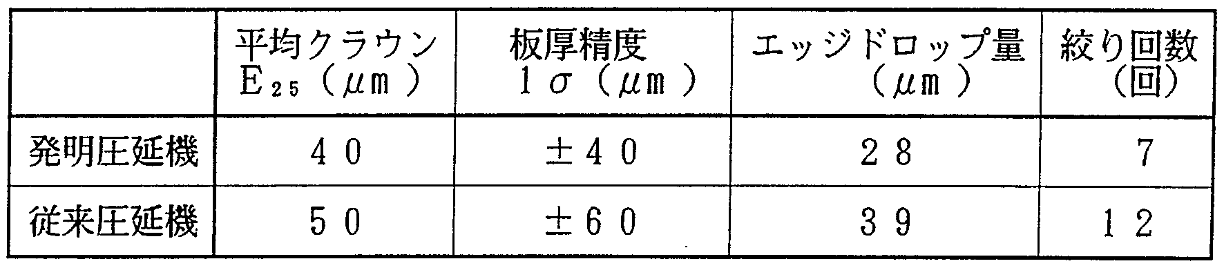
- the inventive rolling mill and the conventional rolling mill were further rolled to 100,000 tons, the number of times of drawing and the amount of edge drop were as shown in Table 4, and according to this table.
- the inventive rolling mill was far superior to the conventional rolling mill in both thickness accuracy and threadability (reduction in drawing).
- the edge drop amount was defined as the thickness deviation at 100 mm and 7.5 mm from the edge.
- the rolling mill of the present invention in applying the rolling mill of the present invention to cold rolling. Particularly in the case of performing edge drop control, the deformation in the strip width direction becomes smaller as the rolled sheet shifts to the post-stage of the cold rolling. Must be placed in the first stand, and It is preferable to extend the scope of application to columns. Moreover, tension is applied between the stands of the cold rolling mill, and the meandering of the sheet is restricted.However, if the hot rolled sheet has a large camber wedge, the narrowing caused by these will occur. May be. However, in this rolling mill, the barrel length of the intermediate roll is lengthened to ensure longitudinal rigidity, so that it is possible to avoid the occurrence of drawing.
- each intermediate roll 3 has a tapered portion 3a at the barrel end portion opposite to each other and a uniform diameter portion 3b which is adjacent to the tapered portion 3a and occupies most of the roll length. It consists of existing rolls.
- Each of the intermediate rolls 3 has such a length that it can contact the knock-up roll 4 over its entire length in its maximum shift position.
- the tapered portion 3a has an extended area extending beyond the barrel end of the back-up roll 4 to the roll end side when the shift amount is zero.
- the tapered portion 3a is applied to at least the backup roll 4, and usually to both the work roll 2 and the back-up roll 4 even when the work roll 2 is shifted, when a rolling load is applied. In contact, it functions to effectively reduce the contact linear pressure between those rolls. Therefore, by appropriately selecting the contact position of the tapered portion 3a with the work roll 2 and the backup roll 4 by the shift of the intermediate roll 3, the plate crane can be controlled as required. .
- the contour of the tapered portion 3a in the cross section including the axis is a tapered shape as shown in Fig. 17 according to the required sheet crown, the maximum shift amount of the intermediate roll, and the like.
- the shape may be a sine or cosine curve as shown in Fig. 18 (a) or a higher-order function curve of second, fourth or sixth order or more as shown in Fig. 18 (b). it can.
- FIG. 20 is a graph showing the linear pressure distribution between the upper roll 1 and the intermediate roll 3.
- the intermediate roll 3 acts on the lower crawl 2.
- the pressure at the portion of the work roll 2 that contacts the tapered portion 3a decreases as the diameter of the work roll 2 decreases, corresponding to the tapered shape of the tapered portion 3a. It is the smallest value at the barrel end of roll 2. Therefore, the work roll 2 is curved in a convex shape as a whole, and the plate crown of the plate 13 is effectively reduced as compared with the case where the intermediate roll 3 is not shifted. .
- the intermediate roll 3 has a longer length than the backup roll 4, and even if the intermediate roll 3 is shifted, the intermediate roll 3 3, the contact length between the knock-up roll 4 and the work roll 2 does not change, and the vertical stiffness of the rolling mill does not change.Thus, the thickness accuracy of hot finish rolling is greatly improved. Moreover, even when the sheet bar is off-center with respect to the center of the rolling mill, the change in linear pressure on the left and right sides of the rolling mill is smaller than in the conventional technology, and the change in the flatness between the rolls, and consequently, Since the plate edge becomes smaller, the bending of the plate can be effectively reduced. (Concrete example)
- a sheet bar with a width of 900 to 1600 mm and a thickness of 40 mm is used, and a finished thickness of 1.6 to 3.
- a barrel length of their respective work roll and backup roll and 2300 mm, in the barrel of the intermediate rolls was a 3000 mm, the tapered portion of the intermediate rolls, 1. 6 X 10 one 3 ( 0.32mm / 200mm diameter) and the roll was shifted from 0mm to 700mm.
- FIG. 22 shows a rolling mill in which the barrel length of the work roll 2 is longer than the barrel length of the intermediate roll 3 in the six-high rolling mill shown in FIG.
- this rolling mill as well, a comparison was made between the case where this rolling mill was used and the case where a conventional rolling mill was used, with respect to the distribution of plate crowns with respect to the number of rolling rolls.
- a six-high rolling mill having the configuration shown in FIG. 22 was arranged in the third stage after the hot finishing rolling mill row, and was rolled under the same conditions as in the processing in Example 4 above. For every 5 coils in this process, the plate crown was measured at a position 25 nm from the edge.
- the tapered mouth of the intermediate roll is the same as in Example 4. Lute paper was applied, and the intermediate roll was shifted from 0 nun to 700 mm.
- the specifications of the conventional rolling mill to be compared are the same as in the case of the fourth embodiment.
- Figure 23 shows the measurement results of the sheet crown. According to the drawing, it is clear that when the rolling mill of the present invention is used, even if the target crown is changed, it is possible to perform highly accurate sheet rolling that is very close to it.
- the rolling mill shown in Fig. 24 is an example in which the intermediate roll 3 is provided with a double-tapered roll crown whose diameter gradually decreases from the center of the barrel toward each of the barrel ends. It is the same as the rolling mill shown in (1). That is, each of the intermediate rolls 3 has a tapered portion 3a that tapers at the barrel end portion opposite to each other, and is adjacent to this portion 3a, and is gradually inclined to the other end of the roll. It is configured by a roll having a tapered portion 3b that is tapered, that is, a roll having an asymmetric roll crown in middle and high. Each of such intermediate rolls 3 has a length capable of contacting the backup roll 4 over its entire length even in the maximum shift posture.
- the tapered portion 3a is slightly reduced when a rolling load is applied.
- At least the backup roll 4 usually, even if the work roll 2 is shifted, contacts both the work roll 2 and the backup roll 4 to effectively reduce the contact linear pressure between the rolls. Function. Therefore, by appropriately selecting the position of the boundary between the tapered portions 3a and 3b by the shift of the intermediate roll 3, the sheet crown can be controlled as required.
- the contour shape of the intermediate roll in the cross section including the axis is determined according to the required sheet crown, the maximum shift amount of the intermediate roll, and the like, in addition to the double taper shape shown in FIG.
- the shape can be a sine or cosine curve as shown in Fig. (A), or a higher-order function curve of second, fourth, sixth or higher order as shown in Fig. (B). Note that the contour shapes of both tapered portions may be the same or different.
- the linear pressure distribution between the upper work roll 2 and the intermediate roll 3 is the same as that shown in FIG. 20, that is, the pressure acting on the work roll 2 from the intermediate roll 3 is expressed as follows.
- the diameter decreases as the diameter of the crawl portion decreases, corresponding to the tapered shape of the tapered portion.
- the work roll 2 is curved as a whole to have a downwardly convex shape, and the plate crown of the plate 13 is effectively reduced as compared with the case where the intermediate roll 3 is not shifted. It is.
- a sheet bar with a width of 900 to 1600 mm and a thickness of 40 mm was used, and a finished thickness of 1.6 to 3.2 mm. This was rolled into a thin low-carbon pan plate.
- the ⁇ crown was measured at a position 25 mm from the edge for every 5 coils in this process.
- the barrel length of each of the work roll and the hack-up roll was 2300 ram
- the barrel length of the intermediate roll was 3000
- the tapered portion 3a of the intermediate roll was 1.6 xl0- 3 (0.32 Jo / 200 mm per diameter) of Te one path shape and the tapered Ri moiety 3 b, with a 0. 1 X 10_ 3 (0. 02mm ⁇ 200 ⁇ per diameter) of tape path shape
- the intermediate roll was shifted from 0 mm to 700 mffl.
- inventive rolling mill when the above-described inventive rolling mill and the conventional rolling mill were further rolled by 100,000 tons, the number of times of drawing, the thickness accuracy, and the average value of the sheet crown were as shown in Table 7. According to the present invention, the inventive rolling mill was far superior to the conventional rolling mill in both thickness accuracy and threadability (reduction in drawing).
- FIG. 28 shows a rolling mill in which the barrel length of the work roll 2 is longer than the barrel length of the intermediate roll 3 in the six-high rolling mill shown in FIG.
- a six-high rolling mill having the configuration shown in FIG. 28 was arranged in the third stand after the hot finishing rolling mill row, and was rolled under the same conditions as the processing in Example 1 above. For every 5 coils in this treatment, the plate crown at a position 25 mm from the edge was measured.
- the barrel length of one crawl is 3400 mm
- the barrel length of the middle roll is 3000 mm nmi
- the barrel length of the knock-up roll is 2300 mm.
- the intermediate roll was shifted from 0 mm to 700 mm.
- the specifications of the conventional rolling mill to be compared are the same as those in the sixth embodiment.
- Fig. 29 shows the measurement results of the sheet crown. According to the drawing, it is clear that when the rolling mill of the present invention is used, even if the target crown is changed, it is possible to perform highly accurate sheet rolling that is very close to it.
- the six-high rolling mill shown in FIG. 30 is an example in which an S-shaped roll crown is provided on the intermediate roll 3 and a single tapered roll crown is provided on the work roll 2.
- the work roll 2 is shifted from the arrangement shown in FIG. 31 (a) as shown in FIG. Since the roll gap between the upper and lower work rolls 2 is directly widened at the side end of 13, the edge drop can be further reduced. Also, as shown in FIG. 32, by shifting work roll 2, By adjusting the distance EL (see Fig. 31) from the starting point of the narrowed portion 2a to the plate edge, the edge drop can be changed, and if the target edge drop amount is given, the work roll shift Thus, edge drop control becomes possible.
- a sheet bar having a width of 900 to 1600 mm and a thickness of 40 mni was obtained, and a finished thickness of 1.6 to 3 .
- each of the work roll and the backup roll is 2300 mm
- the barrel length of the intermediate roll is 3000 mm. with imparting Jo of roll crown, the tapered portion 2 a of the Wa crawling, and Te one path Fushimi of 0. 8 X 10- 3 (0. 1 6mm / 200mm diameter per), the intermediate rolls from 0 mm 700 mm The range was shifted.
- Conventional rolling mill
- a six-high rolling mill is provided in the three subsequent stands including the final stand, each of which consists of flat rolls and has a work roll, an intermediate roll and a backup roll, each of which has a 2300 mm length.
- the final stand each of which consists of flat rolls and has a work roll, an intermediate roll and a backup roll, each of which has a 2300 mm length.
- the same rolling as in the case of the inventive rolling mill was performed, and the same sheet crown measurement was performed as in that case.
- Table 9 shows the number of times of drawing, the amount of edge drop, the thickness accuracy, and the average value of the plate crown when the above-mentioned inventive rolling mill and the conventional rolling mill were further rolled to 100,000 tons. According to this table, the inventive rolling mill was far superior to the conventional rolling mill in both the thickness accuracy and the threadability (reduction of drawing). However, the edge drop amount was the difference between the thickness of the edge of 100 mm and the thickness of 25 mm. Table 9
- the 6-high rolling mill shown in Fig. 30 was placed on the i-th stand of a row of cold rolling mills consisting of 4 stands, and a coil with a width of 900 to 1100 and a thickness of 2 to 3 mm was formed. Rolling to a thin low carbon steel sheet having a finished thickness of 0.5 mm was performed. The plate thickness deviation at the position of 100 film from the edge of the plate subjected to this treatment was examined.
- the diameter difference between the maximum and minimum diameter of the intermediate roll is assuming that the barrel length of the work roll is 2000 mm, the resole length of the intermediate roll is 2700 ram, and the barrel length of the knock-up roll is 20000 mm.
- a 6-high rolling mill consisting of flat rolls, each with a barrel length of 2000 l ⁇ , each of which has a barrel length of 2000 l ⁇ , and an intermediate roll and a backup roll, is installed. Then, while shifting the intermediate roll, cold rolling was performed in the same manner as in the case of the inventive rolling mill, and the thickness deviation was measured in the same manner.
- Figure 34 shows the measurement results of the thickness deviation. According to the figure, it is clear that the use of the rolling mill of the present invention has greatly reduced the occurrence of edge drop.
- FIG. 35 shows a rolling mill in which the work roll 2 is provided with a double-tapered roll crown in the six-high rolling mill shown in FIG.
- this rolling mill as well, a comparison was made between the case where this rolling mill was used and the case where a conventional rolling mill was used, regarding the sheet crown distribution with respect to the number of rolls.
- a six-high rolling mill having the configuration shown in FIG. 35 was placed in the third stage after the hot finishing rolling mill row, and was rolled under the same conditions as the processing in Example 8 above.
- the plate crown was measured at 25ffliD from the edge for every 5 coils in this process.
- both the tapered portions 2a and 2b of the work roll are formed into a taper of 0.4 x lO " 3 (0.008mm / 200fflm diameter), and the intermediate roll is changed from Omni to 700 ⁇ .
- the specifications of the conventional rolling mill to be compared are the same as those in the eighth embodiment.
- FIG. 37 shows a rolling mill in which the barrel length of the work opening 2 is longer than the barrel length of the intermediate roll 3 in the six-high rolling mill shown in FIG.
- a six-high rolling mill having the configuration shown in FIG. 37 was arranged in the third stand after the hot finishing rolling mill row, and was rolled under the same conditions as the processing in Example 10 described above. For every 5 coils in this treatment, the plate crown at a position 25 mm from the edge was measured.
- the barrel length of the work roll is 3400 mm
- the dimensions and shape of the intermediate roll were the same as in Example 10, and the intermediate roll was shifted from 0 mm to 700 mm.
- the specifications of the conventional rolling mill to be compared are the same as in the case of Example 10.
- Fig. 38 shows the measurement results for the crown of the strip. According to the drawing, it is clear that when the rolling mill of the present invention is used, even if the target crown is changed, it is possible to perform high-precision rolling that is extremely close to that.
- FIG. 39 shows a rolling mill in which the work roll 2 is provided with a double tapered roll crown in the six-high rolling mill shown in FIG.
- a six-high rolling mill having the configuration shown in FIG. 39 was disposed in the third stand after the hot finishing rolling mill row, and was rolled under the same conditions as the processing in Example 11 above. For every 5 coils in this process, the crown of the plate was measured at a position 25 hidden from the edge.
- the size and shape of a roll was the same as in Example 11, the tapered portion 2 a of the work rolls 2 0.8 X 10- 3 (0.16 mra / 200 mm per diameter) and the 2 b a 0.01 X 10 "3 with the (0.02 mm / / 200mm per diameter) of Te one path shape, the intermediate roll was shifted in the range of 0 marrow of 700 Jour.
- the specifications of the conventional rolling mill to comparison example 11 Is the same as
- FIG. 40 shows the measurement results of the crown of the sheet. According to the figure, when the rolling mill of the present invention is used, the target crown It is clear that even if the power is changed, it is possible to perform highly accurate plate rolling that is very close to that.
- the six-high rolling mill shown in FIG. 41 is an example in which a single tapered roll crank is provided to the intermediate roll 3 and the work orifice 2.
- a 6-high rolling mill with the configuration shown in Fig. 41 is placed in the rear 3 stands In the rolling mill train, a sheet bar with a width of 900 to 1600 mm and a thickness of 40 mm was rolled into a thin low-carbon steel sheet with a finish thickness of 1.6 to 3.2 mm. The plate crown at a position 25 mm from the edge was measured for each of the five coils in this process.
- the barrel length of their respective work roll and backup roll and 2300 mm, in the barrel of the intermediate rolls was a 3000 mm, a tapered portion 3 a of the intermediate roll 1.6 X 10- 3 (0.32 with the Jour / 200 per diameter) of the tapered, the tapered portion 2 a of the work rolls, and 0.8 X 10- 3 (0.16 mm / 200 mm per diameter) of Te one path shape, the intermediate rolls from 0 mm 700
- the shift was made in the range of 1.
- a six-high rolling mill consisting of flat rolls, each with a work roll of 2300 mm in length and a middle roll and a backup roll, both of which are 2300 mm long.
- the same rolling was performed as with the invented rolling mill while shifting the intermediate roll, and the same sheet crown measurement was performed as with that case.
- the thickness rolling accuracy and threadability (reduction in drawing) of the inventive rolling mill were far superior to those of the conventional rolling mill.
- FIG. 43 shows a rolling mill of the six-high rolling mill shown in FIG. 41, which is obtained by adding a double-tapered roll crown to the single crawl 2.
- a six-high rolling mill having the configuration shown in FIG. 43 was disposed in the third stage after the hot finishing rolling mill row, and was rolled under the same conditions as in the processing in Example 12 above.
- the plate crown was measured at a position of 25 ⁇ from the edge for every 5 coils in this process.
- the specifications of the conventional rolling mill to be compared are the same as in the case of the thirteenth embodiment.
- Fig. 44 shows the measurement results for the crown of the strip. According to the drawing, it is clear that when the rolling mill of the present invention is used, even if the target crown is changed, it is possible to perform highly accurate sheet rolling that is very close to it.
- FIG. 45 shows a rolling mill in which the barrel length of the work roll 2 is longer than the barrel length of the intermediate roll 3 in the six-high rolling mill shown in FIG.
- a six-high rolling mill having the configuration shown in FIG. 45 was arranged in the third stand after the hot finishing rolling mill row, and was rolled under the same conditions as the processing in Example 1 above.
- the ram crown at 25 ram from the edge was measured for every 5 coils in this process.
- the barrel length of the work roll was 3400 mm
- the barrel length of the intermediate roll was 3000 mm
- the barrel length of the backup roll was 2300 mm.
- Figure 46 shows the measurement results for the plate crown. According to the drawing, it is clear that when the rolling mill of the present invention is used, even if the target crown is changed, it is possible to perform highly accurate sheet rolling that is very close to it.
- FIG. 47 shows a rolling mill in which both the taper of the work opening 2 is added to the work opening 2 in the 6-high rolling mill shown in FIG.
- a six-high rolling mill having the configuration shown in FIG. 47 was arranged in the third stand after the hot finishing rolling mill row, and was rolled under the same conditions as in the processing in Example 13 above. For every 5 coils in this treatment, the plate crown at a position 25 mm from the edge was measured.
- the size and shape of the rolls are the same as in Example 15, the tapered portion 2 a of the work roll, and 0, 8 X 10_ 3 (0. 16niffl / 200 mm per diameter) of Te one path shape, work the other tapered part 2 b of the rolls 2, with a 0. 1 X 10- 3 (0. 02 mm / 200 negation per diameter) of the tapered, was shifted in the range of 700ram the intermediate rolls from 0 mm .
- the specifications of the conventional rolling mill to be compared are the same as in the case of Example 13.
- Fig. 48 shows the measurement results of the sheet crown. The place shown in the figure According to the above, it is clear that when the rolling mill of the present invention is used, even if the target crown is changed, it is possible to perform highly accurate sheet rolling that is very close to that.
- the six-high rolling mill shown in FIG. 49 is an example in which the intermediate roll 3 is provided with a double-tapered crown while the work roll 2 is provided with a single-tapered crown.
- a sheet bar with a width of 900 to 1600nim and a thickness of 40mm, and a thin material with a finishing thickness of 1.6 to 3.2mni Rolling into low carbon steel sheet was performed.
- the plate crown at a position 25 mm from the edge was measured.
- the barrel length of each of the work roll and the backup roll is 2300 mm
- the barrel length of the intermediate roll is 3000 mm
- the tapered portion 3a of the intermediate roll is 1.6 ⁇ 10 ⁇ 3 (0.32
- the tapered portion 3b is tapered at 0.1 xl0 to 3 (0.02 mm per 200mm diameter)
- the tapered portion 2a of the work roll is 0.8 X 10 " 3 (0.16mm / 200mm diameter) and the middle opening was shifted from 0 band to 700mm.
- a six-high rolling mill which consists of flat rolls and has a barrel length of 2300nira and a work roll, an intermediate roll and a backup roll, is installed. While shifting the intermediate roll, the same rolling was performed as in the case of the inventive rolling mill, and the sheet crown measurement was performed in the same manner. Test results
- inventive rolling mill when the above-mentioned inventive rolling mill and the conventional rolling mill were further rolled to 100,000 tons, the number of times of drawing, sheet thickness accuracy, and sheet crown average value were as shown in Table 18. According to the results, the inventive rolling mill was far superior to the conventional rolling mill in both thickness accuracy and threadability (reduction in drawing).
- FIG. 51 shows a rolling mill in which the work opening 2 is provided with a double-tapered roll crown in the six-high rolling mill shown in FIG. 49.
- this rolling mill as well, a comparison was made between the case where this rolling mill was used and the case where a conventional rolling mill was used, with respect to the distribution of plate crowns with respect to the number of rolling rolls.
- a six-high rolling mill having the configuration shown in FIG. 51 was disposed in the third stand after the hot finishing rolling mill row, and was rolled under the same conditions as in the processing in Example 17 described above. For every 5 coils in this treatment, the plate crown at a position 25 mm from the edge was measured.
- the tapered portions 3a and 3b of the intermediate roll 3 and the tapered portion 2a of the work roll 2 have the same tapered shape as in Example 17, and the other tapered portion 2b of the work roll 2 is 0.4 xl
- the tapered shape was 0 " 3 (per 0.08mm / 200mm diameter) and the intermediate roll was shifted in the range of 0mm to 700mm. This is the same as in Example 17.
- Fig. 52 shows the measurement results of the sheet crown. According to the drawing, it is clear that when the rolling mill of the present invention is used, even if the target crown is changed, it is possible to perform highly accurate sheet rolling that is very close to it.
- FIG. 53 shows a rolling mill in which the barrel length of the work orifice 2 is longer than the barrel length of the intermediate roll 3 in the six-high rolling mill shown in FIG.
- the six-high rolling mill having the configuration shown in FIG. 53 was arranged in the three subsequent stands of the row of hot finishing rolling mills, and was rolled under the same conditions as the processing in Example 17 described above.
- the plate crown at a position 25 mm from the edge was measured for each of the five coils in this process.
- the intermediate roll has a double tapered roll similar to that of Example 17.
- the taper and the work roll were provided with the same tapered roll taper as in Example 17, and the intermediate roll was shifted from O mm to 700 mm.
- the specifications of the conventional rolling mill to be compared are the same as in the case of Example 17.
- Fig. 54 shows the measurement results of the sheet crown. According to the drawing, it is clear that when the rolling mill of the present invention is used, even if the target crown is changed, it is possible to perform highly accurate sheet rolling that is very close to it.
- FIG. 55 shows a rolling mill of the six-high rolling mill shown in FIG. 51, in which the work opening 2 is provided with a double tapered roll crown.
- a six-high rolling mill having the configuration shown in FIG. 55 was arranged in the third stage after the hot finishing rolling mill row, and was rolled under the same conditions as the processing in Example 17 described above.
- the plate crown at a position 25 mm from the edge was measured for each of the five coils in this process.
- the roll size and the shape of the intermediate roll are the same as in Example 19, and the tapered portion 2a of the work roll is taped to 0.8 ⁇ 10 ” 3 (0.16mm / 200mm diameter). 2b * The tapered shape was 0.1 x 10 to 3 (per 0.02 dragon Z200nim diameter), and the intermediate roll was shifted from 0 mm to 700 mm.
- the specifications of the conventional rolling mill to be compared are the same as in the case of Example 17.
- Fig. 56 shows the measurement results of the sheet crown. According to the drawing, it is clear that when the rolling mill of the present invention is used, even if the target crown is changed, it is possible to perform highly accurate sheet rolling that is very close to it.
- the present invention it is possible to obtain a rolled plate having a desired plate shape having a desired plate crown and edge drop with high accuracy, and to improve the yield in the next step and to always improve the yield. Stable rolling can be performed. Further, the life of the intermediate roll and the work roll can be extended.
Landscapes
- Engineering & Computer Science (AREA)
- Mechanical Engineering (AREA)
- Reduction Rolling/Reduction Stand/Operation Of Reduction Machine (AREA)
- Control Of Metal Rolling (AREA)
- Metal Rolling (AREA)
Description


Claims
Priority Applications (4)
| Application Number | Priority Date | Filing Date | Title |
|---|---|---|---|
| EP92910178A EP0543014B2 (en) | 1991-05-16 | 1992-05-18 | Six-stage rolling mill |
| DE69226690T DE69226690T3 (de) | 1991-05-16 | 1992-05-18 | Sechs-walzen-walzwerk |
| KR1019930700100A KR100216299B1 (ko) | 1991-05-16 | 1992-05-18 | 6단 압연기 |
| CA002087156A CA2087156C (en) | 1991-05-16 | 1992-05-18 | Six high rolling mill |
Applications Claiming Priority (16)
| Application Number | Priority Date | Filing Date | Title |
|---|---|---|---|
| JP3/139428 | 1991-05-16 | ||
| JP13943191 | 1991-05-16 | ||
| JP13942891 | 1991-05-16 | ||
| JP3/139431 | 1991-05-16 | ||
| JP14415291 | 1991-05-21 | ||
| JP3/144152 | 1991-05-21 | ||
| JP18946891 | 1991-07-04 | ||
| JP3/189469 | 1991-07-04 | ||
| JP18946991 | 1991-07-04 | ||
| JP3/189468 | 1991-07-04 | ||
| JP3/189470 | 1991-07-04 | ||
| JP18947091 | 1991-07-04 | ||
| JP18946791 | 1991-07-04 | ||
| JP3/189467 | 1991-07-04 | ||
| JP94292 | 1992-01-07 | ||
| JP4/942 | 1992-01-07 |
Publications (1)
| Publication Number | Publication Date |
|---|---|
| WO1992020471A1 true WO1992020471A1 (fr) | 1992-11-26 |
Family
ID=27571416
Family Applications (1)
| Application Number | Title | Priority Date | Filing Date |
|---|---|---|---|
| PCT/JP1992/000639 WO1992020471A1 (fr) | 1991-05-16 | 1992-05-18 | Laminoir a six etages |
Country Status (6)
| Country | Link |
|---|---|
| EP (1) | EP0543014B2 (ja) |
| JP (1) | JP2654313B2 (ja) |
| KR (1) | KR100216299B1 (ja) |
| CA (1) | CA2087156C (ja) |
| DE (1) | DE69226690T3 (ja) |
| WO (1) | WO1992020471A1 (ja) |
Families Citing this family (7)
| Publication number | Priority date | Publication date | Assignee | Title |
|---|---|---|---|---|
| DE102004020131A1 (de) * | 2003-12-19 | 2005-07-21 | Sms Demag Ag | Kombinierte Fahrweisen und Gerüsttypen in Kalttandemstraßen |
| DE102004020132A1 (de) | 2003-12-23 | 2005-07-28 | Sms Demag Ag | Verfahren und Walzgerüst zur mehrfachen Profilbeeinflussung |
| US7757531B2 (en) | 2004-09-14 | 2010-07-20 | Sms Siemag Aktiengesellschaft | Convex roll used for influencing the profile and flatness of a milled strip |
| JP4928653B1 (ja) * | 2011-09-20 | 2012-05-09 | 三菱日立製鉄機械株式会社 | 冷間圧延機、タンデム圧延設備、可逆圧延設備、圧延設備の改造方法および冷間圧延機の運転方法 |
| FR3006211B1 (fr) | 2013-05-28 | 2015-05-15 | Fives Dms | Procede de changement de configuration d'un laminoir et laminoir pour la mise en oeuvre du procede. |
| JP6470134B2 (ja) | 2015-07-08 | 2019-02-13 | Primetals Technologies Japan株式会社 | 圧延機および圧延方法 |
| JP7342831B2 (ja) * | 2020-09-29 | 2023-09-12 | Jfeスチール株式会社 | 熱間圧延機及び熱延鋼板の製造方法 |
Citations (4)
| Publication number | Priority date | Publication date | Assignee | Title |
|---|---|---|---|---|
| JPS5413442A (en) * | 1977-07-01 | 1979-01-31 | Hitachi Ltd | Rolling mill series for controlling sheet crown and shape |
| JPS58187207A (ja) * | 1982-04-10 | 1983-11-01 | エス・エム・エス・シユレ−マン−ジ−マ−ク・アクチエンゲゼルシヤフト | 軸方向に摺動可能なロ−ルを備えたロ−ルスタンド |
| JPS5956905A (ja) * | 1982-09-28 | 1984-04-02 | Kawasaki Steel Corp | 調質圧延用6段圧延機 |
| JPS62282717A (ja) * | 1986-05-30 | 1987-12-08 | Kawasaki Heavy Ind Ltd | 圧延方法 |
Family Cites Families (15)
| Publication number | Priority date | Publication date | Assignee | Title |
|---|---|---|---|---|
| JPS5220018B2 (ja) * | 1973-05-16 | 1977-06-01 | ||
| JPS5944125B2 (ja) * | 1978-08-03 | 1984-10-26 | 新日本製鐵株式会社 | 6段圧延機 |
| JPS55161512A (en) * | 1979-06-06 | 1980-12-16 | Hitachi Ltd | Roll shifter for rolling mill |
| JPS573401U (ja) * | 1980-06-09 | 1982-01-08 | ||
| JPS6018243B2 (ja) * | 1980-07-07 | 1985-05-09 | 株式会社日立製作所 | 圧延ロ−ル |
| DE3038865C1 (de) † | 1980-10-15 | 1982-12-23 | SMS Schloemann-Siemag AG, 4000 Düsseldorf | Walzgeruest mit axial verschiebbaren Walzen |
| DE3602698A1 (de) * | 1985-04-16 | 1986-10-16 | SMS Schloemann-Siemag AG, 4000 Düsseldorf | Walzgeruest mit axial verschiebbaren walzen |
| JPS62151203A (ja) * | 1985-12-25 | 1987-07-06 | Kawasaki Steel Corp | 板材の圧延方法 |
| JPS6316802A (ja) * | 1986-07-10 | 1988-01-23 | Kawasaki Heavy Ind Ltd | 圧延方法 |
| JPS6360006A (ja) * | 1986-08-29 | 1988-03-16 | Kawasaki Heavy Ind Ltd | 圧延スタンド |
| DE3638331C2 (de) * | 1986-11-10 | 1995-07-13 | Schloemann Siemag Ag | Walzgerüst zum Walzen von Flachmaterial mit einem Paar von axial verschiebbaren Arbeitswalzen |
| DE3712043C2 (de) † | 1987-04-09 | 1995-04-13 | Schloemann Siemag Ag | Walzgerüst mit axial verschiebbaren Walzen |
| JPH01118804U (ja) * | 1988-02-01 | 1989-08-11 | ||
| JPH0313220A (ja) * | 1989-06-09 | 1991-01-22 | Kawasaki Steel Corp | 圧延機 |
| JPH03294006A (ja) * | 1990-04-11 | 1991-12-25 | Kawasaki Steel Corp | 熱間仕上圧延機及び熱間仕上圧延機列 |
-
1992
- 1992-05-18 CA CA002087156A patent/CA2087156C/en not_active Expired - Fee Related
- 1992-05-18 JP JP4125081A patent/JP2654313B2/ja not_active Expired - Lifetime
- 1992-05-18 EP EP92910178A patent/EP0543014B2/en not_active Expired - Lifetime
- 1992-05-18 WO PCT/JP1992/000639 patent/WO1992020471A1/ja active IP Right Grant
- 1992-05-18 DE DE69226690T patent/DE69226690T3/de not_active Expired - Lifetime
- 1992-05-18 KR KR1019930700100A patent/KR100216299B1/ko not_active IP Right Cessation
Patent Citations (4)
| Publication number | Priority date | Publication date | Assignee | Title |
|---|---|---|---|---|
| JPS5413442A (en) * | 1977-07-01 | 1979-01-31 | Hitachi Ltd | Rolling mill series for controlling sheet crown and shape |
| JPS58187207A (ja) * | 1982-04-10 | 1983-11-01 | エス・エム・エス・シユレ−マン−ジ−マ−ク・アクチエンゲゼルシヤフト | 軸方向に摺動可能なロ−ルを備えたロ−ルスタンド |
| JPS5956905A (ja) * | 1982-09-28 | 1984-04-02 | Kawasaki Steel Corp | 調質圧延用6段圧延機 |
| JPS62282717A (ja) * | 1986-05-30 | 1987-12-08 | Kawasaki Heavy Ind Ltd | 圧延方法 |
Non-Patent Citations (1)
| Title |
|---|
| See also references of EP0543014A4 * |
Also Published As
| Publication number | Publication date |
|---|---|
| JPH05245506A (ja) | 1993-09-24 |
| KR930701244A (ko) | 1993-06-11 |
| KR100216299B1 (ko) | 1999-08-16 |
| EP0543014B1 (en) | 1998-08-19 |
| DE69226690D1 (de) | 1998-09-24 |
| EP0543014A1 (en) | 1993-05-26 |
| EP0543014A4 (ja) | 1995-05-24 |
| DE69226690T2 (de) | 1999-01-07 |
| DE69226690T3 (de) | 2005-02-10 |
| EP0543014B2 (en) | 2004-10-27 |
| CA2087156A1 (en) | 1992-11-17 |
| JP2654313B2 (ja) | 1997-09-17 |
| CA2087156C (en) | 2000-12-26 |
Similar Documents
| Publication | Publication Date | Title |
|---|---|---|
| CN102548678B (zh) | 轧钢机及轧钢机的调零方法 | |
| JP2009006397A (ja) | T形鋼の製造方法および圧延設備列 | |
| JP4847111B2 (ja) | 多段式圧延機及び多段式圧延機の制御方法 | |
| CN100358646C (zh) | 金属板材的轧制方法和轧制装置 | |
| US5622073A (en) | Six high rolling mill | |
| WO1992020471A1 (fr) | Laminoir a six etages | |
| CN114011884A (zh) | 冷轧宽幅板的板形控制方法 | |
| JP4238198B2 (ja) | スキンパス圧延機およびその圧延方法 | |
| JP3924276B2 (ja) | 薄手広幅厚板材の矯正方法 | |
| JP4623738B2 (ja) | 冷間圧延における形状制御方法 | |
| JP2008254026A (ja) | プレス成形性に優れた高張力金属ストリップの製造方法 | |
| JP3591477B2 (ja) | 圧延方法 | |
| JP4330134B2 (ja) | 冷間圧延における形状制御方法 | |
| JP2003048009A (ja) | 多段圧延機における形状制御方法 | |
| JP4568164B2 (ja) | 差厚鋼板の圧延矯正方法 | |
| JP2004090079A (ja) | 圧延機のエッジドロップ制御装置 | |
| JP2000079409A (ja) | 多重式圧延機を用いた板形状制御方法 | |
| JPH0351481B2 (ja) | ||
| JP3541973B2 (ja) | 冷間圧延におけるエッジドロップ制御方法 | |
| JP6673285B2 (ja) | 被圧延材の形状制御装置及び形状制御方法ならびに金属薄板の製造方法 | |
| JP2005152932A (ja) | ユニバーサルミル及びこれを用いた鋼板の製造方法 | |
| JP2009183969A (ja) | 冷間圧延における圧延荷重の予測方法 | |
| JPH01321007A (ja) | エツジドロツプ制御手段を含む板材の圧延方法 | |
| JPH10128420A (ja) | 板材の冷間圧延におけるエッジドロップ制御方法 | |
| JP3022222B2 (ja) | 金属板の冷間圧延機 |
Legal Events
| Date | Code | Title | Description |
|---|---|---|---|
| AK | Designated states |
Kind code of ref document: A1 Designated state(s): CA KR US |
|
| AL | Designated countries for regional patents |
Kind code of ref document: A1 Designated state(s): AT BE CH DE DK ES FR GB GR IT LU MC NL SE |
|
| WWE | Wipo information: entry into national phase |
Ref document number: 2087156 Country of ref document: CA Ref document number: 1992910178 Country of ref document: EP |
|
| WWE | Wipo information: entry into national phase |
Ref document number: 1019930700100 Country of ref document: KR |
|
| WWP | Wipo information: published in national office |
Ref document number: 1992910178 Country of ref document: EP |
|
| WWG | Wipo information: grant in national office |
Ref document number: 1992910178 Country of ref document: EP |