US9965686B2 - Image capture apparatus that identifies object, image capture control method, and storage medium - Google Patents
Image capture apparatus that identifies object, image capture control method, and storage medium Download PDFInfo
- Publication number
- US9965686B2 US9965686B2 US15/072,952 US201615072952A US9965686B2 US 9965686 B2 US9965686 B2 US 9965686B2 US 201615072952 A US201615072952 A US 201615072952A US 9965686 B2 US9965686 B2 US 9965686B2
- Authority
- US
- United States
- Prior art keywords
- image capture
- unit
- location
- information obtaining
- image
- Prior art date
- Legal status (The legal status is an assumption and is not a legal conclusion. Google has not performed a legal analysis and makes no representation as to the accuracy of the status listed.)
- Active
Links
- 238000000034 method Methods 0.000 title claims description 9
- 238000004891 communication Methods 0.000 claims description 21
- 230000001133 acceleration Effects 0.000 claims description 9
- 230000005358 geomagnetic field Effects 0.000 claims description 3
- 230000006870 function Effects 0.000 description 19
- 230000003287 optical effect Effects 0.000 description 9
- 230000004048 modification Effects 0.000 description 7
- 238000012986 modification Methods 0.000 description 7
- 238000006243 chemical reaction Methods 0.000 description 6
- 238000010586 diagram Methods 0.000 description 6
- 230000005693 optoelectronics Effects 0.000 description 5
- 230000008901 benefit Effects 0.000 description 3
- 230000010365 information processing Effects 0.000 description 2
- 239000004065 semiconductor Substances 0.000 description 2
- 230000008859 change Effects 0.000 description 1
- 230000000295 complement effect Effects 0.000 description 1
- 238000001514 detection method Methods 0.000 description 1
- 238000009434 installation Methods 0.000 description 1
- 229910044991 metal oxide Inorganic materials 0.000 description 1
- 150000004706 metal oxides Chemical class 0.000 description 1
- 230000002093 peripheral effect Effects 0.000 description 1
Images


Classifications
-
- G06K9/00771—
-
- H—ELECTRICITY
- H04—ELECTRIC COMMUNICATION TECHNIQUE
- H04N—PICTORIAL COMMUNICATION, e.g. TELEVISION
- H04N23/00—Cameras or camera modules comprising electronic image sensors; Control thereof
- H04N23/60—Control of cameras or camera modules
- H04N23/66—Remote control of cameras or camera parts, e.g. by remote control devices
-
- G—PHYSICS
- G06—COMPUTING; CALCULATING OR COUNTING
- G06T—IMAGE DATA PROCESSING OR GENERATION, IN GENERAL
- G06T7/00—Image analysis
- G06T7/70—Determining position or orientation of objects or cameras
-
- G—PHYSICS
- G06—COMPUTING; CALCULATING OR COUNTING
- G06V—IMAGE OR VIDEO RECOGNITION OR UNDERSTANDING
- G06V20/00—Scenes; Scene-specific elements
- G06V20/50—Context or environment of the image
- G06V20/52—Surveillance or monitoring of activities, e.g. for recognising suspicious objects
-
- H—ELECTRICITY
- H04—ELECTRIC COMMUNICATION TECHNIQUE
- H04N—PICTORIAL COMMUNICATION, e.g. TELEVISION
- H04N23/00—Cameras or camera modules comprising electronic image sensors; Control thereof
- H04N23/60—Control of cameras or camera modules
- H04N23/62—Control of parameters via user interfaces
-
- H—ELECTRICITY
- H04—ELECTRIC COMMUNICATION TECHNIQUE
- H04N—PICTORIAL COMMUNICATION, e.g. TELEVISION
- H04N23/00—Cameras or camera modules comprising electronic image sensors; Control thereof
- H04N23/60—Control of cameras or camera modules
- H04N23/66—Remote control of cameras or camera parts, e.g. by remote control devices
- H04N23/661—Transmitting camera control signals through networks, e.g. control via the Internet
-
- H—ELECTRICITY
- H04—ELECTRIC COMMUNICATION TECHNIQUE
- H04W—WIRELESS COMMUNICATION NETWORKS
- H04W4/00—Services specially adapted for wireless communication networks; Facilities therefor
- H04W4/02—Services making use of location information
-
- H—ELECTRICITY
- H04—ELECTRIC COMMUNICATION TECHNIQUE
- H04W—WIRELESS COMMUNICATION NETWORKS
- H04W64/00—Locating users or terminals or network equipment for network management purposes, e.g. mobility management
-
- G—PHYSICS
- G06—COMPUTING; CALCULATING OR COUNTING
- G06T—IMAGE DATA PROCESSING OR GENERATION, IN GENERAL
- G06T2207/00—Indexing scheme for image analysis or image enhancement
- G06T2207/30—Subject of image; Context of image processing
- G06T2207/30196—Human being; Person
Definitions
- the present invention relates to an image capture apparatus that identifies an object, an image capture control method, and a storage medium.
- Japanese Unexamined Patent Application Publication No. 2013-085200 discloses a method of identifying an individual by determining whether an object that matches characteristic information is present in an image being captured, the characteristic information being stored in association with an identifier detected in a range of an angle of view (capture location) of image capture.
- An aspect of an image capture apparatus comprises:
- a first information obtaining unit that obtains information on a location of the apparatus during image capture by the image capture unit
- a second information obtaining unit that obtains direction of an object in an image captured by the image capture unit
- a third information obtaining unit that obtains information on a location of a wireless device that is included by the object during image capture by the image capture unit;
- a fourth information obtaining unit that obtains a distance of the object in the image captured by the image capture unit from the apparatus
- a calculating unit that calculates a location of the object based on the information on the location of the apparatus obtained by the first information obtaining unit, the direction of the object in the image obtained by the second information obtaining unit, and the distance of the object from the apparatus obtained by the fourth information obtaining unit;
- an identifying unit that identifies the object as the object including the wireless device if the location of the object calculated by the calculating unit and the location of the wireless device obtained by the third information obtaining unit are within a predetermined range.
- An aspect of an image capture control method according to the present invention is the image capture control method performed in an image capture apparatus having an image capture unit, comprising:
- An aspect of a storage medium according to the present invention is a non-transitory computer readable storage medium storing a program that causes a computer to implement an image capture control function, the program being executed in the image capture apparatus having an image capture unit,
- storage medium causes the computer to perform:
- an identifying function of identifying the object as the object including the wireless device if the location of the object calculated by the calculating function and the location of the wireless device obtained by the third information obtaining function are within a predetermined range.
- FIG. 1 is a schematic view illustrating a system configuration of an image capture system according to an embodiment of the present invention
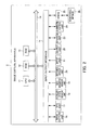
- FIG. 2 is a block diagram illustrating a hardware configuration of the image capture apparatus
- FIG. 3 is a block diagram showing a hardware configuration of a wireless device
- FIG. 4 is a functional block diagram showing a functional configuration for executing object identifying processing, among the functional configurations of the image capture apparatus;
- FIG. 5 is a schematic view showing a surface distance to the object
- FIG. 6 is a schematic view showing a state in which the object with the wireless device is captured in a captured image without being shielded;
- FIG. 7 is a schematic view showing a state in which the object with the wireless device is partially shielded in a captured image.
- FIG. 8 is a flowchart illustrating a flow of the object identifying processing executed by the image capture apparatus of FIG. 2 having the functional configuration of FIG. 4 .
- FIG. 1 is a schematic view illustrating a system configuration of an image capture system 1 according to an embodiment of the present invention
- the image capture system 1 is configured to include an image capture apparatus 2 and a wireless device 3 that are configured to be communicable with each other via radio communication (BLE (Bluetooth (registered trademark) Low Energy), iBeacon, etc.).
- BLE Bluetooth (registered trademark) Low Energy
- iBeacon iBeacon
- FIG. 2 is a block diagram illustrating a hardware configuration of the image capture apparatus 2 .
- the image capture apparatus 2 is configured as, for example, a digital camera.
- the image capture apparatus 2 includes a CPU (Central Processing Unit) 11 , ROM (Read Only Memory) 12 , RAM (Random Access Memory) 13 , a bus 14 , an input/output interface 15 , an image capture unit 16 , an GPS (Global Positioning System) unit 17 , an acceleration sensor unit 18 , a geomagnetic sensor unit 19 , a distance sensor unit 20 , an input unit 21 , an output unit 22 , a storing unit 23 , a communication unit 24 , and a drive 25 .
- CPU Central Processing Unit
- ROM Read Only Memory
- RAM Random Access Memory
- a bus 14 an input/output interface 15
- an image capture unit 16 includes a GPS (Global Positioning System) unit 17 , an acceleration sensor unit 18 , a geomagnetic sensor unit 19 , a distance sensor unit 20 , an input unit 21 , an output unit 22 , a storing unit 23 , a communication unit 24 , and a drive 25 .
- GPS Global Positioning System
- the CPU 11 executes various processing according to a program that is recorded in the ROM 12 , or a program that is loaded from the storing unit 23 to the RAM 13 .
- the RAM 13 also stores data and the like necessary for the CPU 11 to execute the various processing, as appropriate.
- the CPU 11 , the ROM 12 and the RAM 13 are connected to one another via the bus 14 .
- the input/output interface 15 is also connected to the bus 14 .
- the image capture unit 16 , the GPS unit 17 , the acceleration sensor unit 18 , the geomagnetic sensor unit 19 , the distance sensor unit 20 , the input unit 21 , the output unit 22 , the storing unit 23 , the communication unit 24 , and the drive 25 are connected.
- the image capture unit 16 includes an optical lens unit and an image sensor, which are not shown.
- the optical lens unit is configured by a lens such as a focus lens and a zoom lens for condensing light.
- the focus lens is a lens for forming an image of a subject on the light receiving surface of the image sensor.
- the zoom lens is a lens that causes the focal length to freely change in a certain range.
- the optical lens unit also includes peripheral circuits to adjust setting parameters such as focus, exposure, white balance, and the like, as necessary.
- the image sensor is configured by an optoelectronic conversion device, an AFE (Analog Front End), and the like.
- the optoelectronic conversion device is configured by a CMOS (Complementary Metal Oxide Semiconductor) type of optoelectronic conversion device and the like, for example.
- CMOS Complementary Metal Oxide Semiconductor
- Light incident through the optical lens unit forms an image of an object in the optoelectronic conversion device.
- the optoelectronic conversion device optoelectronically converts (i.e. captures) the image of the object, accumulates the resultant image signal for a predetermined time interval, and sequentially supplies the image signal as an analog signal to the AFE.
- the AFE executes a variety of signal processing such as A/D (Analog/Digital) conversion processing of the analog signal.
- the variety of signal processing generates a digital signal that is output as an output signal from the image capture unit 16 .
- Such the output signal of the image capture unit 16 is hereinafter referred to as “data of a captured image”. Data of the captured image is supplied to the CPU 11 , and the like as appropriate.
- the GPS unit 17 detects a location (latitude, longitude, altitude) of the image capture apparatus 2 and current time indicated by the GPS, based on a GPS signal received from a GPS satellite.
- the acceleration sensor unit 18 detects respective three-axis acceleration in the image capture apparatus 2 .
- the geomagnetic sensor unit 19 detects an orientation of geomagnetic field.
- the distance sensor unit 20 is configured with a range imagery sensor or a device such as a stereo camera, and detects a distance from the image capture apparatus 2 to an object.
- the distance sensor unit 20 detects distances to objects at a plurality of locations within an angle of view of the image capture apparatus 2 . It should be noted that, other than detection by the distance sensor unit 20 , the distance to the object can also be detected by using a ranging function for the AF (Auto Focus) control of the image capture unit 16 .
- the input unit 21 is configured by various buttons and the like, and inputs a variety of information in accordance with instruction operations by a user.
- the output unit 22 is configured by a display unit, a speaker, and the like, and outputs images and sound.
- the storing unit 23 is configured by a hard disk, DRAM (Dynamic Random Access Memory) or the like, and stores data of various images.
- DRAM Dynamic Random Access Memory
- the communication unit 24 controls communication with other devices (not illustrated) via networks including the Internet.
- the communication unit 24 controls communication with the wireless device 3 , by radio communication such as BLE and iBeacon.
- a removable medium 26 composed of a magnetic disk, an optical disk, a magneto-optical disk, semiconductor memory or the like is installed in the drive 25 , as appropriate. Programs that are read via the drive 25 from the removable medium 26 are installed in the storing unit 23 , as necessary. Similarly to the storing unit 23 , the removable medium 26 can also store a variety of data such as the image data stored in the storing unit 23 .
- FIG. 3 is a block diagram showing a hardware configuration of the wireless device 3 .
- the wireless device 3 is provided with a CPU 31 , ROM 31 , RAM 33 , a bus 34 , an input/output interface 35 , a GPS unit 36 , an input unit 37 , and a communication unit 38 .
- These functional units have similar configurations to the functional units of the image capture apparatus 2 illustrated in FIG. 2 .
- FIG. 4 is a functional block diagram showing a functional configuration for executing object identifying processing, among the functional configurations of the image capture apparatus 2 .
- the object identifying processing is processing of identifying a captured object based on the direction and distance of an object detected by the image capture apparatus 2 , and a location of the wireless device 3 submitted from the wireless device 3 .
- processing of obtaining the location of the wireless device 3 at the predetermined time interval (for example, every second) and processing of submitting the location thus obtained to the image capture apparatus 2 along with information indicating communication time are repeated in the wireless device 3 .
- a location obtaining unit 51 Upon performing the object identifying processing, as illustrated in FIG. 4 , a location obtaining unit 51 , a direction obtaining unit 52 , an attitude obtaining unit 53 , a distance obtaining unit 54 , an device information obtaining unit 55 , an object identifying unit 56 , a record controlling unit 57 , a capture controlling unit 58 , and an object location calculating unit 59 function in the CPU 11 .
- a region of the storing unit 23 is provided with an image storing unit 61 and a device information storing unit 62 .
- the image storing unit 61 stores data of captured images captured by the image capture apparatus 2 .
- the device information storing unit 62 stores information (ID, communication time, location information and the like of the wireless device 3 ) regarding the wireless device 3 with which the image capture apparatus 2 had radio communication.
- the location obtaining unit 51 as a first information obtaining unit obtains a location (latitude, longitude and altitude) of the image capture apparatus 2 detected by the GPS unit 17 .
- the direction obtaining unit 52 as a second information obtaining unit obtains a direction of the image capture apparatus 2 based on an orientation of geomagnetic field detected by the geomagnetic sensor unit 19 .
- the attitude obtaining unit 53 obtains attitude of the image capture apparatus 2 based on three-axis acceleration in the image capture apparatus 2 detected by the acceleration sensor unit 18 .
- the attitude obtaining unit 53 detects an elevation angle or a depression angle of the image capture device 2 based on a horizontal direction.
- the distance obtaining unit 54 as a fourth information obtaining unit obtains a distance on a land surface (a surface distance) to the object, based on a distance detected by the distance sensor unit 20 .
- FIG. 5 is a schematic view showing the surface distance to the object.
- the device information obtaining unit 55 as a third information obtaining unit obtains information regarding the wireless device 3 (ID, communication time, location information and the like of the wireless device 3 ) via the communication unit 24 .
- the object location calculating unit 59 as a calculating unit calculates the direction of the object based on: the location, an azimuth angle, and the elevation angle or the depression angle of the image capture apparatus 2 during image capture in the image capture apparatus 2 ; information on an angle of view of the image capture apparatus 2 (focal length of lens, etc.); and a location of the image of the object in the captured image, and calculates the location of the object based on: the direction thus calculated; and the distance (the surface distance) obtained by the distance obtaining unit 54 .
- the object identifying unit 56 as an identifying unit determines whether the location of the object calculated by the object location calculating unit 59 matches the information regarding the wireless device 3 (location of the wireless device 3 ) obtained by the device information obtaining unit 55 (specifically, it is determined whether the location of the object is included within a specified range from the location of the wireless device 3 ), and, if there is a match, identifies the object captured in the captured image as an object with the wireless device 3 (an owner of the wireless device 3 ).
- FIG. 6 is a schematic view showing a state in which the object with the wireless device 3 is captured in the captured image without being shielded.
- the direction of the object is calculated based on: the location, the azimuth angel, and the elevation angle or the depression angle of the image capture apparatus 2 during image capture; information on the angle of view of the image capture apparatus 2 (focal length of lens, etc.); and the location of the image of the object in the captured image, and the location of the object is calculated based on: the direction thus calculated; and the distance (the surface distance) obtained by the distance obtaining unit 54 .
- the location of the object thus calculated matches the information regarding the wireless device 3 (location of the wireless device 3 ), and, if there is a match, the object captured in the captured image is identified as the object with the wireless device 3 (the owner of the wireless device 3 ).
- the wireless device 3 the owner of the wireless device 3
- the user A and the user B are determined to be captured in the captured image.
- FIG. 7 is a schematic view showing a state in which the object with the wireless device 3 is partially shielded in a captured image.
- the direction of the object is calculated based on: the location, the azimuth angel, and the elevation angle or the depression angle of the image capture apparatus 2 during image capture; information on the angle of view of the image capture apparatus 2 (the focal length of lens, etc.); and the location of the image of the object in the captured image, and the location of the object is calculated based on: the direction thus calculated; and the distance (the surface distance) obtained by the distance obtaining unit 54 .
- the location of the object thus calculated matches the information regarding the wireless device 3 (the location of the wireless device 3 ), and, if there is a match, the object captured in the captured image is identified as the object with the wireless device 3 (the owner of the wireless device 3 ).
- the wireless device 3 the owner of the wireless device 3 .
- the user A is determined to be captured in the captured image.
- the distance obtaining unit 54 since the distance (the surface distances) to the object (shield) obtained by the distance obtaining unit 54 does not match the distance calculated from the location of the wireless device 3 and the location of the image capture apparatus 2 , the user B is determined not to be captured in the captured image.
- the record controlling unit 57 adds information regarding the wireless device 3 (for example, ID of wireless device 3 ) to data of the captured image captured by the image capture apparatus 2 , in a case in which the object with the wireless device 3 is identified by the object identifying unit 56 . This allows the user to know that the object with the wireless device 3 is captured in the captured image.
- the record controlling unit 57 can add the location in the angle of view and the information regarding the wireless device 3 in association with each other. In such a case, in addition to knowing that the object with the wireless device 3 is captured in the captured image, one can know the object at which location is the object with the wireless device 3 .
- the capture controlling unit 58 controls image capture in the image capture apparatus 2 according to user settings. For example, the capture controlling unit 58 controls interval photography according to a capture interval and capture duration specified by the user.
- FIG. 8 is a flowchart illustrating a flow of the object identifying processing executed by the image capture apparatus 2 of FIG. 2 having the functional configuration of FIG. 4 .
- the object identifying processing starts by the user's operation on the input unit 21 to start the object identifying processing. It should be noted that, in the present embodiment, the object identifying processing performed during interval photography is described as an example.
- Step S 1 the device information obtaining unit 55 obtains information regarding the wireless device 3 .
- the information regarding the wireless device 3 is received sequentially and stored in the device information storing unit 62 .
- Step S 2 the capture control unit 58 performs image capture.
- Step S 3 the capture control unit 58 stores the captured image, capture time, information on the angle of view, the location of the image capture apparatus 2 , the azimuth angle, and the elevation angle or the depression angle.
- Step S 4 the object location calculating unit 59 determines whether the capture time matches the communication time in the information regarding the wireless device 3 .
- Step S 4 determination in Step S 4 is YES and processing proceeds to Step S 5 .
- Step S 4 determination in Step S 4 is NO and processing proceeds to Step S 9 .
- Step S 5 the object location calculating unit 59 calculates the direction of the object based on: the location, the azimuth angle, and the elevation angle or the depression angle of the image capture apparatus 2 at the capture time matching the communication time; information on the angle of view of the image capture apparatus 2 (the focal length of lens, etc.); and the location of the image of the object in the captured image.
- Step S 6 the object location calculating unit 59 calculates the location of the object based on: the direction thus calculated; and the distance (the surface distance) obtained by the distance obtaining unit 54 .
- Step S 7 the object identifying unit 56 determines whether the location of the object thus calculated matches the information regarding the wireless device 3 (location of the wireless device 3 ).
- Step S 6 determination in Step S 6 is YES and the processing proceeds to Step S 8 .
- Step S 7 determination in Step S 7 is NO and the processing proceeds to Step S 9 .
- Step S 8 the object identifying unit 56 adds the information regarding the wireless device 3 (here, ID of the wireless device 3 ) to the captured image and stores to the image storing unit 61 .
- Step S 9 the capture control unit 58 determines whether or not completion of image capture has been instructed.
- Step S 9 determination in Step S 9 is NO and the processing proceeds to Step S 10 .
- Step S 9 determination in Step S 9 is YES and the object identifying processing terminates.
- Step S 10 the capture control unit 58 determines whether or not the capture interval (interval time) of the interval photography has elapsed.
- Step S 10 determines whether the capture interval of the interval photography has not elapsed. If the capture interval of the interval photography has not elapsed, determination in Step S 10 is NO and the processing of Step S 10 is repeated.
- Step S 10 determines whether the capture interval of the interval photography has elapsed. If the capture interval of the interval photography has elapsed, determination in Step S 10 is YES and the processing proceeds to Step S 2 .
- the above described processing calculates the direction of the object based on: the location, the azimuth angle, and the elevation angle or the depression angle of the image capture apparatus 2 during image capture; information on the angle of view of the image capture apparatus 2 (the focal length of lens, etc.); and the location of the image of the object in the captured image, and calculates the location of the object based on: the direction thus calculated; and the distance (the surface distance) obtained by the distance obtaining unit 54 . And then, it is determined whether the location of the object thus calculated matches the information regarding the wireless device 3 (location of the wireless device 3 ), and, if there is a match, the object captured in the captured image is identified as the object with the wireless device 3 (the owner of the wireless device 3 ).
- the object ID is thus added to the captured image, by specifying the ID of the wireless device 3 upon search in stored images, only images stored with the ID are returned. In other words, the user can select only images in which the user him/herself is captured.
- the object identifying processing in the object identifying unit 56 according to the above described embodiment can also be the following processing.
- the object location calculating unit 59 calculates the direction of the object based on: the location, the azimuth angle, and the elevation angle or the depression angle of the image capture apparatus 2 during image capture in the image capture apparatus 2 ; information on the angle of view of the image capture apparatus 2 (the focal length of lens, etc.); and the location of the image of the object in the captured image.
- the object location calculating unit 59 calculates the direction and distance from the image capture apparatus 2 to the wireless device 3 based on the location of the image capture apparatus 2 and the information regarding the wireless device 3 (the location of the wireless device 3 ).
- the object identifying unit 56 determines whether the direction of the object thus calculated and the distance obtained by the distance obtaining unit 54 match the direction and the distance from the image capture apparatus 2 to the wireless device 3 thus calculated, and, if there is a match, the object captured in the captured image is identified as the object with the wireless device 3 (the owner of the wireless device 3 ).
- This also allows determination of the state in which the object with the wireless device 3 is not captured in the captured image due to shielding by the shield or the like.
- determination can be made as to whether or not the direction of the object in the captured image matches the direction of the wireless device 3 obtained from the information regarding the wireless device 3 , to thereby determine whether the object is captured in the captured image.
- the ID of the wireless device 3 can be added to the captured image, and the object can be identified.
- the ID assigned to the user can be added to the captured image and can be stored.
- existence of the user at the location shielded by the shield or the like can be indicated by displaying a message (ID displaying in a balloon, etc.).
- the user can be associated with the captured image of the situation where the user was present, even if the user is not visually recognizable as the object.
- the image capture apparatus 2 thus configured includes: the image capture unit 16 (the image capture unit); the location obtaining unit 51 (the first information obtaining unit); the direction obtaining unit 52 (the second information obtaining unit); the device information obtaining unit 55 (the third information obtaining unit); the distance obtaining unit 54 (the fourth information obtaining unit); the object location calculating unit 59 ; and the object identifying unit 56 (the identifying unit).
- the location obtaining unit 51 (the first information obtaining unit) obtains information on the location of the image capture apparatus 2 during image capture by the image capture unit 16 .
- the direction obtaining unit 52 obtains direction of the image in the image captured by the image capture unit 16 (the image capture unit).
- the device information obtaining unit 55 (the third information obtaining unit) obtains information on the location of the wireless device 3 that is included by the object during image capture by the image capture unit 16 (the image capture unit).
- the distance obtaining unit 54 obtains the distance of the object in the image captured by the image capture unit 16 (the image capture unit) from the image capture apparatus 2 .
- the object location calculating unit 59 calculates the location of the object based on the information on the location of the image capture apparatus 2 obtained by the location obtaining unit 51 (the first information obtaining unit), the direction of the image in the image obtained by the direction obtaining unit 52 (the second information obtaining unit), and the distance of the object from the image capture apparatus 2 obtained by the distance obtaining unit 54 (the fourth information obtaining unit).
- the object identifying unit 56 (the identifying unit) identifies the object as the object including the wireless device 3 if the location of the object calculated by the object location calculating unit 59 (the calculating unit) and the location of the wireless device 3 obtained by the device information obtaining unit 55 (the third information obtaining unit) are within a predetermined range.
- the object being present in the angle of view can be identified, and it is easier to determine upon image capture whether or not the particular individual appears in the captured image.
- the image capture apparatus 2 further includes the attitude obtaining unit 53 .
- the attitude obtaining unit 53 obtains any one of the elevation angle and the depression angle of the image capture apparatus 2 .
- the direction obtaining unit 52 obtains the direction of the object.
- the direction of the object in the image is represented by the azimuth angle, and any one of the elevation angle and the depression angle.
- the object location calculating unit 59 calculates the location of the object based on the direction of the object in the image and the location of the image of the object in the image captured by the image capture unit 16 (the image capture unit).
- the wireless device 3 includes the identifying number being set that allows for identification of the wireless device 3 .
- the image capture apparatus 2 stores the captured image including the object thus identified along with the identifying number.
- the object identifying unit 56 (the identifying unit) identifies the object as the object shielded by the shield if the location of the object calculated by the object location calculating unit 59 (the calculating unit) and the location of the wireless device 3 obtained by the device information obtaining unit 55 (the third information obtaining unit) are out of the predetermined range.
- the user can be associated with the captured image of the situation where the user was present, even if the user is not visually recognizable as the object.
- the object identifying processing is described to be performed in the image capture apparatus 2 ; however, the present invention is not limited thereto.
- the object identifying processing can also be performed by an information processing apparatus and the like without the image capture function, by using the captured image and information obtained in the image capture apparatus 2 during image capture.
- the object identifying processing is described to be performed after capture of the image; however, the present invention is not limited thereto.
- the object identifying processing can also be performed during capture of the image, and, at the completion of the capture, the ID of the wireless device 3 of the object captured in the image can then be added to the captured image.
- the image capture device 2 to which the present invention is applied is the digital camera; however, the present invention is not particularly limited thereto.
- the present invention can be applied to any electronic apparatus in general with an information processing function. More specifically, for example, the present invention can be applied to a laptop personal computer, a printer, a television receiver, a video camera, a portable navigation device, a cell phone device, a smartphone, a portable gaming device, and the like.
- the processing sequence described above can be executed by hardware, and can also be executed by software.
- FIG. 4 the hardware configurations of FIG. 4 are merely illustrative examples, and the present invention is not particularly limited thereto. More specifically, the types of functional blocks employed to realize the above-described functions are not particularly limited to the examples shown in FIG. 4 , so long as the image capture apparatus 2 can be provided with the functions enabling the aforementioned processing sequence to be executed in its entirety.
- a single functional block may be configured by a single piece of hardware, a single installation of software, or any combination thereof.
- a program configuring the software is installed from a network or a storage medium into a computer or the like.
- the computer may be a computer embedded in dedicated hardware.
- the computer may be a computer capable of executing various functions by installing various programs, e.g., a general-purpose personal computer.
- the storage medium containing such a program can not only be constituted by the removable medium 31 of FIG. 1 distributed separately from the device main body for supplying the program to the user, but also can be constituted by a storage medium or the like supplied to the user in a state incorporated in the device main body in advance.
- the removable medium 26 is composed of, for example, a magnetic disk (including a floppy disk), an optical disk, a magnetic optical disk, or the like.
- the optical disk is composed of, for example, a CD-ROM (Compact Disk-Read Only Memory), a DVD (Digital Versatile Disk), Blu-ray (Registered Trademark) disk or the like.
- the magnetic optical disk is composed of an MD (Mini-Disk) or the like.
- the storage medium supplied to the user in a state incorporated in the device main body in advance may include, for example, the ROM 12 shown in FIG. 2 , a hard disk included in the storing unit 23 shown in FIG. 2 or the like, in which the program is recorded.
- the steps describing the program recorded in the storage medium include not only the processing executed in a time series following this order, but also processing executed in parallel or individually, which is not necessarily executed in the time series.
- a term system shall mean a general device configured from a plurality of devices, a plurality of circuits, and the like.
Landscapes
- Engineering & Computer Science (AREA)
- Signal Processing (AREA)
- Multimedia (AREA)
- Physics & Mathematics (AREA)
- General Physics & Mathematics (AREA)
- Theoretical Computer Science (AREA)
- Computer Networks & Wireless Communication (AREA)
- Computer Vision & Pattern Recognition (AREA)
- Human Computer Interaction (AREA)
- Studio Devices (AREA)
- Details Of Cameras Including Film Mechanisms (AREA)
- Camera Data Copying Or Recording (AREA)
Applications Claiming Priority (2)
| Application Number | Priority Date | Filing Date | Title |
|---|---|---|---|
| JP2015-115269 | 2015-06-05 | ||
| JP2015115269A JP6623568B2 (ja) | 2015-06-05 | 2015-06-05 | 撮像装置、撮像制御方法及びプログラム |
Publications (2)
| Publication Number | Publication Date |
|---|---|
| US20160358019A1 US20160358019A1 (en) | 2016-12-08 |
| US9965686B2 true US9965686B2 (en) | 2018-05-08 |
Family
ID=57452099
Family Applications (1)
| Application Number | Title | Priority Date | Filing Date |
|---|---|---|---|
| US15/072,952 Active US9965686B2 (en) | 2015-06-05 | 2016-03-17 | Image capture apparatus that identifies object, image capture control method, and storage medium |
Country Status (3)
| Country | Link |
|---|---|
| US (1) | US9965686B2 (ja) |
| JP (1) | JP6623568B2 (ja) |
| CN (1) | CN106254755B (ja) |
Families Citing this family (4)
| Publication number | Priority date | Publication date | Assignee | Title |
|---|---|---|---|---|
| TWI642002B (zh) * | 2017-04-14 | 2018-11-21 | 李雨暹 | 適地性空間物件可視範圍管理方法與系統 |
| JP2019086365A (ja) * | 2017-11-06 | 2019-06-06 | 株式会社日立製作所 | 位置推定システム |
| US20190180472A1 (en) * | 2017-12-08 | 2019-06-13 | Electronics And Telecommunications Research Institute | Method and apparatus for determining precise positioning |
| KR20210112800A (ko) * | 2020-03-06 | 2021-09-15 | 한국전자통신연구원 | 객체 추적 장치 및 방법 |
Citations (9)
| Publication number | Priority date | Publication date | Assignee | Title |
|---|---|---|---|---|
| JP2002314851A (ja) | 2001-04-10 | 2002-10-25 | Nikon Corp | 撮影装置 |
| JP2002344789A (ja) | 2001-05-16 | 2002-11-29 | Fuji Photo Film Co Ltd | 撮像装置および位置情報検出システム |
| US6724421B1 (en) * | 1994-11-22 | 2004-04-20 | Sensormatic Electronics Corporation | Video surveillance system with pilot and slave cameras |
| US6801637B2 (en) * | 1999-08-10 | 2004-10-05 | Cybernet Systems Corporation | Optical body tracker |
| JP2006195786A (ja) | 2005-01-14 | 2006-07-27 | Canon Inc | 画像データ検索方法・画像データ検索装置及びプログラム |
| US7830962B1 (en) * | 1998-03-19 | 2010-11-09 | Fernandez Dennis S | Monitoring remote patients |
| US8027577B2 (en) * | 2009-02-03 | 2011-09-27 | Hoya Corporation | Camera |
| JP2013085200A (ja) | 2011-10-12 | 2013-05-09 | Canon Inc | 画像処理装置、画像処理方法、及びプログラム |
| US20150206012A1 (en) * | 2014-01-18 | 2015-07-23 | Jigabot, Llc | System for automatically tracking a target |
Family Cites Families (11)
| Publication number | Priority date | Publication date | Assignee | Title |
|---|---|---|---|---|
| JP2004364044A (ja) * | 2003-06-05 | 2004-12-24 | Sony Corp | 画像記録装置 |
| JP4932400B2 (ja) * | 2006-09-19 | 2012-05-16 | 株式会社リコー | 撮像装置 |
| KR100843094B1 (ko) * | 2006-10-30 | 2008-07-02 | 삼성전자주식회사 | 이미지 파일 관리 장치 및 방법 |
| JP2011078008A (ja) * | 2009-10-01 | 2011-04-14 | Nippon Hoso Kyokai <Nhk> | コンテンツ共有装置、コンテンツ編集装置、コンテンツ共有プログラム、およびコンテンツ編集プログラム |
| JP5045776B2 (ja) * | 2010-03-23 | 2012-10-10 | カシオ計算機株式会社 | カメラ、カメラ制御プログラム及び撮影方法並びに被写体情報送受信システム |
| JP5549515B2 (ja) * | 2010-10-05 | 2014-07-16 | カシオ計算機株式会社 | 撮像装置及び方法、並びにプログラム |
| US8587672B2 (en) * | 2011-01-31 | 2013-11-19 | Home Box Office, Inc. | Real-time visible-talent tracking system |
| JP2013213903A (ja) * | 2012-04-02 | 2013-10-17 | Xacti Corp | 撮像装置 |
| JP5861667B2 (ja) * | 2013-05-31 | 2016-02-16 | カシオ計算機株式会社 | 情報処理装置、撮像システム、撮像装置、情報処理方法及びプログラム |
| JP6076852B2 (ja) * | 2013-07-11 | 2017-02-08 | 株式会社 日立産業制御ソリューションズ | カメラシステム、その制御方法およびその制御プログラム |
| JP2015055865A (ja) * | 2013-09-13 | 2015-03-23 | 株式会社リコー | 撮影システム及び撮影方法 |
-
2015
- 2015-06-05 JP JP2015115269A patent/JP6623568B2/ja active Active
-
2016
- 2016-03-17 US US15/072,952 patent/US9965686B2/en active Active
- 2016-03-18 CN CN201610157694.9A patent/CN106254755B/zh not_active Expired - Fee Related
Patent Citations (9)
| Publication number | Priority date | Publication date | Assignee | Title |
|---|---|---|---|---|
| US6724421B1 (en) * | 1994-11-22 | 2004-04-20 | Sensormatic Electronics Corporation | Video surveillance system with pilot and slave cameras |
| US7830962B1 (en) * | 1998-03-19 | 2010-11-09 | Fernandez Dennis S | Monitoring remote patients |
| US6801637B2 (en) * | 1999-08-10 | 2004-10-05 | Cybernet Systems Corporation | Optical body tracker |
| JP2002314851A (ja) | 2001-04-10 | 2002-10-25 | Nikon Corp | 撮影装置 |
| JP2002344789A (ja) | 2001-05-16 | 2002-11-29 | Fuji Photo Film Co Ltd | 撮像装置および位置情報検出システム |
| JP2006195786A (ja) | 2005-01-14 | 2006-07-27 | Canon Inc | 画像データ検索方法・画像データ検索装置及びプログラム |
| US8027577B2 (en) * | 2009-02-03 | 2011-09-27 | Hoya Corporation | Camera |
| JP2013085200A (ja) | 2011-10-12 | 2013-05-09 | Canon Inc | 画像処理装置、画像処理方法、及びプログラム |
| US20150206012A1 (en) * | 2014-01-18 | 2015-07-23 | Jigabot, Llc | System for automatically tracking a target |
Also Published As
| Publication number | Publication date |
|---|---|
| JP6623568B2 (ja) | 2019-12-25 |
| JP2017005395A (ja) | 2017-01-05 |
| CN106254755A (zh) | 2016-12-21 |
| US20160358019A1 (en) | 2016-12-08 |
| CN106254755B (zh) | 2019-06-07 |
Similar Documents
| Publication | Publication Date | Title |
|---|---|---|
| US9961214B2 (en) | Image shooting apparatus for adding information to image | |
| JP5109836B2 (ja) | 撮像装置 | |
| US9965686B2 (en) | Image capture apparatus that identifies object, image capture control method, and storage medium | |
| US10432853B2 (en) | Image processing for automatic detection of focus area | |
| JP6146464B2 (ja) | 撮影装置、情報取得装置、情報取得システム、送信制御方法、情報取得方法及びプログラム | |
| JP2017005395A5 (ja) | ||
| US10254410B2 (en) | Positioning control method, positioning device and storage medium | |
| EP3340210A1 (en) | Information processing device, move locus information output method and program | |
| WO2018079043A1 (ja) | 情報処理装置、撮像装置、情報処理システム、情報処理方法、およびプログラム | |
| US20220082706A1 (en) | Positioning control device | |
| JP2009111827A (ja) | 撮影装置及び画像ファイル提供システム | |
| CN116405774A (zh) | 视频处理方法与电子设备 | |
| JP2017199972A (ja) | 端末装置、情報取得システム、情報取得方法およびプログラム | |
| US20120113251A1 (en) | Method and apparatus for calculating position information of an image | |
| US20120246180A1 (en) | Portable device | |
| JP2014180036A (ja) | 撮影装置、その制御方法、及びプログラム | |
| JP2011199358A (ja) | 測位機能を有する撮像装置 | |
| JP5773753B2 (ja) | 撮像装置および制御方法 | |
| US20150089085A1 (en) | Input processing system, information storage device, information processing device, and input method | |
| JP6331562B2 (ja) | 特定装置、特定方法及びプログラム | |
| JP2011188265A (ja) | デジタルカメラ | |
| JP2018096746A (ja) | 位置特定装置、位置特定方法及びプログラム | |
| JP2005164805A (ja) | 撮影装置 | |
| JP2013207326A (ja) | 撮影装置、および位置情報処理方法 | |
| JP2016208119A (ja) | 情報処理装置、情報処理方法、コンピュータプログラム、及び記憶媒体 |
Legal Events
| Date | Code | Title | Description |
|---|---|---|---|
| AS | Assignment |
Owner name: CASIO COMPUTER CO., LTD., JAPAN Free format text: ASSIGNMENT OF ASSIGNORS INTEREST;ASSIGNORS:KATO, HIROYUKI;ODA, MASAHIRO;NAKANO, KANAKO;SIGNING DATES FROM 20160303 TO 20160305;REEL/FRAME:038015/0497 |
|
| STCF | Information on status: patent grant |
Free format text: PATENTED CASE |
|
| MAFP | Maintenance fee payment |
Free format text: PAYMENT OF MAINTENANCE FEE, 4TH YEAR, LARGE ENTITY (ORIGINAL EVENT CODE: M1551); ENTITY STATUS OF PATENT OWNER: LARGE ENTITY Year of fee payment: 4 |