US9623693B2 - Printer cover locking mechanism - Google Patents
Printer cover locking mechanism Download PDFInfo
- Publication number
- US9623693B2 US9623693B2 US14/780,139 US201314780139A US9623693B2 US 9623693 B2 US9623693 B2 US 9623693B2 US 201314780139 A US201314780139 A US 201314780139A US 9623693 B2 US9623693 B2 US 9623693B2
- Authority
- US
- United States
- Prior art keywords
- printer
- platen roller
- cover
- print head
- push
- Prior art date
- Legal status (The legal status is an assumption and is not a legal conclusion. Google has not performed a legal analysis and makes no representation as to the accuracy of the status listed.)
- Active
Links
Images


Classifications
-
- B—PERFORMING OPERATIONS; TRANSPORTING
- B41—PRINTING; LINING MACHINES; TYPEWRITERS; STAMPS
- B41J—TYPEWRITERS; SELECTIVE PRINTING MECHANISMS, i.e. MECHANISMS PRINTING OTHERWISE THAN FROM A FORME; CORRECTION OF TYPOGRAPHICAL ERRORS
- B41J29/00—Details of, or accessories for, typewriters or selective printing mechanisms not otherwise provided for
- B41J29/54—Locking devices applied to printing mechanisms
- B41J29/56—Locking devices applied to printing mechanisms and manually actuated
-
- B—PERFORMING OPERATIONS; TRANSPORTING
- B41—PRINTING; LINING MACHINES; TYPEWRITERS; STAMPS
- B41J—TYPEWRITERS; SELECTIVE PRINTING MECHANISMS, i.e. MECHANISMS PRINTING OTHERWISE THAN FROM A FORME; CORRECTION OF TYPOGRAPHICAL ERRORS
- B41J15/00—Devices or arrangements of selective printing mechanisms, e.g. ink-jet printers or thermal printers, specially adapted for supporting or handling copy material in continuous form, e.g. webs
- B41J15/04—Supporting, feeding, or guiding devices; Mountings for web rolls or spindles
- B41J15/042—Supporting, feeding, or guiding devices; Mountings for web rolls or spindles for loading rolled-up continuous copy material into printers, e.g. for replacing a used-up paper roll; Point-of-sale printers with openable casings allowing access to the rolled-up continuous copy material
-
- B—PERFORMING OPERATIONS; TRANSPORTING
- B41—PRINTING; LINING MACHINES; TYPEWRITERS; STAMPS
- B41J—TYPEWRITERS; SELECTIVE PRINTING MECHANISMS, i.e. MECHANISMS PRINTING OTHERWISE THAN FROM A FORME; CORRECTION OF TYPOGRAPHICAL ERRORS
- B41J29/00—Details of, or accessories for, typewriters or selective printing mechanisms not otherwise provided for
- B41J29/12—Guards, shields or dust excluders
- B41J29/13—Cases or covers
-
- E—FIXED CONSTRUCTIONS
- E05—LOCKS; KEYS; WINDOW OR DOOR FITTINGS; SAFES
- E05C—BOLTS OR FASTENING DEVICES FOR WINGS, SPECIALLY FOR DOORS OR WINDOWS
- E05C19/00—Other devices specially designed for securing wings, e.g. with suction cups
Definitions
- the present disclosure relates to a printer cover locking mechanism.
- the present disclosure relates to a printer locking mechanism capable of reducing a number of parts and conserving assembly space.
- a mechanism surrounding a print head in a printing part of a printer includes various complex parts such as a head-attaching member or a heat dissipation plate. Accordingly, a cost thereof is increased and an assembly space thereof is enlarged.
- the abovementioned mechanism surrounding the print head and the abovementioned mechanism surrounding the cover lock have both been in need of a more simplified configuration.
- Patent Literature 1 JP-UM-B-H7-046538
- a present disclosure has been conceived of in view of various conventional problems. As a result, a printer cover locking mechanism that is capable of reducing a number of parts and conserving assembly space is proposed.
- the present disclosure proposes a printer cover locking mechanism in which a mechanism surrounding a print head is further simplified.
- the present disclosure proposes a printer cover locking mechanism in which a mechanism surrounding a cover lock related to an opening and closing of an opening and closing cover is further simplified.
- the present disclosure proposes a printer cover locking mechanism in which a heat dissipation mechanism of a print head is further simplified.
- the printer cover locking mechanism includes: a printer housing; an opening and closing cover configured to open and close with respect to the printer housing; a print head attached to one of: the printer housing or the opening and closing cover, the print head capable of printing on print paper loaded into the printer housing; a platen roller attached to another of: the printer housing or the opening and closing cover, the platen roller capable of feeding the print paper by sandwiching and rotating the print paper between the print head and the platen roller; and a cover lock configured to cause the print head to contact with the platen roller by engaging with the platen roller and configured to cause the print head to separate from the platen roller by disengaging from the platen roller.
- the cover lock is attached to the print head, and allows dissipation of heat generated from the print head.
- a push-release button is operated to separate the platen roller from the print head may be further included.
- An abutting inclined plate that opposes the push-release button may be included, with the abutting inclined plate integrated with the cover lock.
- a platen roller lock engaging part may be formed on the cover lock, the platen roller lock engaging part configured to engage with the lock pin and disengage from the lock pin, with the lock pin attached to a printer shaft of the platen roller.
- a tapered surface may be formed on the cover lock, with the tapered surface abutting against the lock pin attached to the printer shaft of the platen roller.
- the abutting inclined plate of the cover lock may incline in a direction that approaches a rear surface side of the press-release button.
- the abutting inclined plate of the cover lock may be positioned in a vicinity of an ejection port that dispenses the print paper printed by the print head to outside of the printer housing.
- a spring-attaching protrusion may be formed on the cover lock, with the spring-attaching protrusion attached to a head-biasing spring biasing the print head in a direction toward the platen roller, and a recess that opposes the print head may be formed on an inner wall surface of the spring-attaching protrusion.
- a material of the cover lock may be an iron material having a plated surface.
- the print head may be attached to the printer housing, and the platen roller may be attached to the opening and closing cover.
- a printer cover locking mechanism has a heat dissipating function in a cover lock attached to a print head. As a result, it is not necessary to provide a conventionally required heat dissipation plate. Therefore, the number of parts may be reduced, the assembly space may be conserved, the cost may be decreased, and the printer may be miniaturized.
- FIG. 1 shows a perspective view of a portable printer 1 equipped with a cover locking mechanism 10 according to an embodiment of a present disclosure
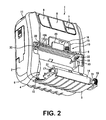
- FIG. 2 similarly, shows a perspective view of an opening and closing cover 3 of the portable printer 1 , in an opened condition with respect to a printer housing 2 ;
- FIG. 3 similarly, shows a cross-sectional view of a main part of a cover locking mechanism 10 (push-release button 20 );
- FIG. 4 similarly, shows a perspective view of a cover lock 27 ;
- FIG. 5 similarly, shows a perspective view indicating an integrated structure of a cover lock 27 and a thermal head 13 .
- a cover lock attached to a print head has a heat dissipating function.
- a printer cover locking mechanism allows for a reduction in number of parts, a conservation of assembly space, and a decrease in cost, and a miniaturization of the printer to be achieved.
- FIG. 1 shows a perspective view of the printer, e.g., a portable printer 1 .
- the portable printer 1 is a thermal printer.
- the portable printer 1 includes: a printer housing 2 ; and an opening and closing cover 3 .
- FIG. 2 shows a perspective view of an opening and closing cover 3 of the portable printer 1 , in an opened condition with respect to a printer housing 2 .
- the portable printer 1 further includes: a feeding part 5 of a roll-shaped continuous label body 4 (print paper); a printing part 6 ; an inputting part 7 ; a displaying part 8 ; a power switch 9 ; and a cover locking mechanism 10 .
- the printer housing 2 has an operator-portable size.
- a belt-hanging part 11 is included on an upper side, and the entire portable printer 1 is hangable from a shoulder of an operator by a shoulder-hanging belt (not shown).
- the entire portable printer 1 is also attachable to a waist of the operator.
- an opening and closing cover surrounding a cover shaft 12 positioned at a lower corner part may open and close. As a result, it is possible for storing the continuous label body 4 in the feeding part 5 and for loading into the portable printer 1 .
- the continuous label body 4 has a plurality of label pieces temporarily attached onto a strip-shaped mount or backing strip.
- the label piece is a so-called “thermal label.” It is possible to print by coating a thermosensitive color developing layer onto a surface of the label piece. It is possible for the feeding part 5 to store the continuous label body 4 in an inner part of the feeding part by winding the continuous label body 4 into a rolled shape, and to unwind the continuous label body 4 into a strip shape in a direction toward the printing part 6 .
- the printing part 6 includes: a thermal head 13 attached to the printer housing 2 ; a platen roller 14 attached to a side of the opening and closing cover 3 , and that allows for feed of the continuous label body 4 ; a head-biasing spring 15 configured to bias the thermal head 13 in a direction toward the platen roller 14 ; and a driving motor 16 .
- the platen roller gear 18 and the connecting gear 19 are mutually engaged by closing the printer housing 2 of the opening and closing cover 3 , and the platen roller 14 may be rotary driven by the driving motor 16 .
- thermal printing is applied to the continuous label body 4 (label piece) by sandwiching the continuous label body 4 between the thermal head 13 and the platen roller 14 , by rotary driving the platen roller 14 via the driving motor 16 , and by having the heating element 13 A of the thermal head 13 generate heat in response to print data fed into the thermal head 13 .
- the inputting part 7 is able to input a necessary data or command into the portable printer 1 .
- the displaying part 8 is able to display information input by the inputting part 7 and other required information.
- FIG. 3 shows a cross-sectional view of a main part of a cover locking mechanism 10 (push-release button 20 ).
- the push-release button 20 includes: a button body 21 ; a water-proof adhesive surface 22 formed around a whole circumference of a rim part of the button body 21 ; a button shaft 23 and a button-biasing spring 24 as an elastic member that are integrated with the button body 21 ; and a push-protrusion 25 projecting from a rear surface side of the button body 21 .
- the button body 21 is exposed on a surface side of the printer housing 2 , as shown in FIG. 1 .
- the button body 21 is pressed by an operator using the portable printer 1 towards an inner side of the printer housing 2 (from a right direction to a left direction in FIG. 3 ).
- the water-proof adhesive surface 22 is formed such that the water-proof adhesive surface 22 is sunken in relatively more on an inner side of the printer housing 2 than the button body 21 .
- the water-proof adhesive surface 22 may be positioned on an inner side of the printer housing 2 .
- the water-proof adhesive surface 22 is a flat surface region that is in close contact with an inner wall surface 2 A of the printer housing 2 .
- the water-proof adhesive surface 22 extends along a lengthwise direction of a thermal head 13 (width direction of continuous label body 4 ), so as to be longer than a peak.
- the water-proof adhesive surface 22 may cover the whole heating element 13 A (see, FIG. 2 ) of the thermal head 13 .
- a left and right button shaft 23 is attached to an inner bracket (not shown) of the printer housing 2 .
- the left and right button shaft 23 may rotate the whole push-release button 20 with respect to the printer housing 2 by pressing the button body 21 .
- a left and right button-biasing spring 24 is formed at a tip part of the push-release button 20 by winding along the same plane as the water-proof adhesive surface 22 (see, a broken line of FIG. 1 ). Moreover, the left and right button-biasing spring 24 is configured to raise an abutting shaft part 26 to each tip part thereof located at a region extending from the button body 21 past the left and right button shaft 23 . As shown in FIG.
- buttons-biasing spring 24 may be formed in winding manner.
- integrating the button-biasing spring 24 with the button body 21 has an advantage for the portable printer 1 in particular, because miniaturization is needed.
- the cover lock 27 may rotate around the head shaft 28 on a rear surface side (inner side of the printer housing 2 ) of the push-release button 20 .
- FIG. 4 shows a perspective view of the cover lock 27 .
- FIG. 5 shows a perspective view indicating an integrated structure of the cover lock 27 and the thermal head 13 .
- the thermal head 13 is attached and fixed to the cover lock 27 by an adhesive agent.
- the abutting inclined plate 29 is integrally formed in a region that faces towards the push-protrusion 25 ( FIG. 3 ) and is positioned at a center of an upper frame part of cover lock 27 .
- a left and right platen roller lock engaging part 30 having a section that is substantially semi-circular arc-shaped is formed on a side opposing the push-protrusion 25 via the thermal head 13 .
- the abutting inclined plate 29 of the cover lock 27 inclines in a direction that approaches a rear surface side of the push-release button 20 .
- the abutting inclined plate 29 of the cover lock 27 inclines towards an initial pressing direction (orthogonal direction that faces an inner side of the printer housing 2 ) of the push-release button 20 with respect to the printer housing 2 . Accordingly, a component of a force working in a rotating operation of the cover lock 27 surrounding the head shaft 28 may be made relatively large via an affect from the push-release button 20 (push-protrusion 25 ) on the abutting inclined plate 29 of the cover lock 27 . The force that is necessary to operate the push-release button 20 may be relatively small.
- the left and right platen roller lock engaging part 30 may be engaged with and disengaged from by the left and right lock pin 31 of the platen roller 14 .
- the platen roller 14 is able to abut against the thermal head 13 via application of a specified pressing force (printing pressure) while the left and right lock pin 31 are engaged with the left and right platen roller lock engaging part 30 .
- Printing may be accomplished with the continuous label body 4 sandwiched by the platen roller 14 and the thermal head 13 .
- the push-protrusion 25 located on a rear surface side of the button body 21 opposes the abutting inclined plate 29 of the cover lock 27 .
- the push-protrusion 25 presses the abutting inclined plate 29 via a rotation in a clockwise direction of the push-release button 20 surrounding the left and right button shaft 23 by resisting a biasing force of the left and right button-biasing spring 24 , as shown in FIG. 3 .
- the thermal head 13 and the cover lock 27 rotate surrounding the head shaft 28 by resisting the biasing force of the head-biasing spring 15 in a counter-clockwise direction, as shown in FIG. 3 .
- the left and right lock pin 31 of the platen roller 14 are separated from the left and right platen roller lock engaging part 30 , and the thermal head 13 is separated from the platen roller 14 , such that the continuous label body 4 may be loaded.
- the cover lock 27 may be separated from the platen roller 14 via the abutting inclined plate 29 by the rotation of the push-release button 20 .
- a tapered surface 32 is formed on an upper tip part of the left and right platen roller lock engaging part 30 .
- the cover lock 27 attached to the thermal head 13 causes the platen roller 14 to contact with the thermal head 13 by engaging with the platen roller 14 and causes the platen roller 14 to separate from the thermal head 13 by disengaging from the platen roller 14 resulting from closing and opening of the opening and closing cover 3 , respectively.
- the cover lock 27 may directly dissipate heat generated from the thermal head 13 .
- a material of the cover lock 27 is an iron material. Plate processing with such as zinc or chrome is applied to a surface of the iron material.
- the material of the cover lock 27 may dissipate the heat of the thermal head 13 and may have rigidity or mechanical strength, which may allow engagement with or disengagement from the left and right lock pin 31 of the platen roller 14 .
- the plate processing applied to the iron material may prevent from generating rust caused by rainwater, humidity, or the like, in the portable printer 1 that may be used in outdoor.
- the abutting inclined plate 29 of the cover lock 27 inclines in a direction that approaches towards the rear surface side of the push-release button 20 , and the abutting inclined plate 29 is positioned in a vicinity of an ejection port 33 that dispenses the continuous label body 4 printed by the thermal head 13 to an outside of the printer housing 2 . Accordingly, a heat dissipation effect is improved because the abutting inclined plate 29 is easily exposed to outside air.
- the left and right spring-attaching protrusion 34 (see, FIG. 3 ) which is attached to the head-biasing spring 15 that biases the thermal head 13 in the direction toward the platen roller 14 is formed on the cover lock 27 .
- the recess 35 (see, FIGS. 4 and 5 ) that opposes the thermal head 13 is formed on the inner wall surface of each of the left and right spring-attaching protrusion 34 . Consequently, a surface area of part of the left and right spring-attaching protrusion 34 may be increased, and a heat dissipation effect may be improved.
- a lower side tip part of the water-proof adhesive surface 22 of the push-release button 20 is a tip part 36 for cutting paper.
- the tip part for cutting paper 36 opposes the continuous label body 4 that is fed to the ejection port 33 from between the thermal head 13 and the platen roller 14 .
- the continuous label body 4 (mount and label piece) may be cut at a predetermined region thereof.
- the portable printer 1 is portable such that the thermal head 13 is positioned further above the platen roller 14 .
- the lower side tip part of the push-release button 20 (tip part for cutting paper 36 ) is positioned slightly more on an outer side than on an outer surface (see, space D shown in FIG. 3 ) of a tip part of the opening and closing cover 3 . Accordingly, air between the cover lock 27 and the ejection port 33 of a printed continuous label body 4 does not readily accumulate, and a heat dissipation effect may be smoothly achieved by the cover lock.
- the left and right lock pin 31 of the platen roller 14 abut against the tapered surface 32 of the cover lock 27 .
- the left and right lock pin 31 may engage with the left and right platen roller lock engaging part 30 , the opening and closing cover 3 may be closed, and the continuous label body 4 may be sandwiched between the thermal head 13 and the platen roller 14 .
- the thermal head 13 is directly attached to the cover lock 27 . Therefore, a number of parts is reduced, and heat generated from the thermal head 13 is directly received by the cover lock 27 via a heat conduction effect. As previously described, the cover lock 27 also has heat dissipating function of the heat dissipation plate. Thus, the assembly space may be conserved, and the portable printer 1 may be miniaturized.
- a cover locking mechanism according to the present disclosure may also be applied to a desktop printer or the other type of printer.
- the above embodiment describes a structure, in which a print head (thermal head 13 ) is attached to the printer housing 2 , the platen roller 14 is attached to the opening and closing cover 3 , and the push-release button 20 may rotate with respect to the printer housing 2 .
- a flexibility of design may be improved by selecting an arbitrary combination for each part or relative relationship therebetween.
- the print head (thermal head 13 ) may be attached to the opening and closing cover 3
- the platen roller 14 may be attached to the printer housing 2 .
- the push-release button 20 may rotate towards the opening and closing cover 3 .
Landscapes
- Engineering & Computer Science (AREA)
- Mechanical Engineering (AREA)
- Accessory Devices And Overall Control Thereof (AREA)
- Electronic Switches (AREA)
- Printers Characterized By Their Purpose (AREA)
- Handling Of Continuous Sheets Of Paper (AREA)
- Handling Of Sheets (AREA)
Applications Claiming Priority (3)
| Application Number | Priority Date | Filing Date | Title |
|---|---|---|---|
| JP2013063671A JP6216528B2 (ja) | 2013-03-26 | 2013-03-26 | プリンター |
| JP2013-063671 | 2013-03-26 | ||
| PCT/JP2013/079004 WO2014155800A1 (ja) | 2013-03-26 | 2013-10-25 | プリンターのカバーロック機構 |
Publications (2)
| Publication Number | Publication Date |
|---|---|
| US20160052319A1 US20160052319A1 (en) | 2016-02-25 |
| US9623693B2 true US9623693B2 (en) | 2017-04-18 |
Family
ID=51622838
Family Applications (1)
| Application Number | Title | Priority Date | Filing Date |
|---|---|---|---|
| US14/780,139 Active US9623693B2 (en) | 2013-03-26 | 2013-10-25 | Printer cover locking mechanism |
Country Status (5)
| Country | Link |
|---|---|
| US (1) | US9623693B2 (ja) |
| EP (2) | EP2979883B1 (ja) |
| JP (1) | JP6216528B2 (ja) |
| CN (2) | CN106274087B (ja) |
| WO (1) | WO2014155800A1 (ja) |
Cited By (1)
| Publication number | Priority date | Publication date | Assignee | Title |
|---|---|---|---|---|
| US20220242145A1 (en) * | 2019-10-24 | 2022-08-04 | Brother Kogyo Kabushiki Kaisha | Printing device including restriction member restricting movement of holder holding printing head or platen roller when cover is at position other than closed position |
Families Citing this family (14)
| Publication number | Priority date | Publication date | Assignee | Title |
|---|---|---|---|---|
| JP6422334B2 (ja) * | 2014-12-24 | 2018-11-14 | セイコーインスツル株式会社 | 印字ユニットおよびサーマルプリンタ |
| JP6389415B2 (ja) * | 2014-10-20 | 2018-09-12 | サトーホールディングス株式会社 | プリンタ |
| JP6497901B2 (ja) * | 2014-11-20 | 2019-04-10 | サトーホールディングス株式会社 | プリンタ |
| JP6544933B2 (ja) * | 2015-01-27 | 2019-07-17 | サトーホールディングス株式会社 | プリンタ |
| JP6447248B2 (ja) * | 2015-03-05 | 2019-01-09 | セイコーエプソン株式会社 | プリンター |
| CN104827768B (zh) * | 2015-04-08 | 2016-08-24 | 北京硕方电子科技有限公司 | 一种标签打印机及其机芯 |
| JP2017081129A (ja) * | 2015-10-30 | 2017-05-18 | 富士通コンポーネント株式会社 | プリンタ装置 |
| JP2017196876A (ja) * | 2016-04-28 | 2017-11-02 | 富士通コンポーネント株式会社 | プリンタ装置 |
| GB2559404A (en) | 2017-02-06 | 2018-08-08 | Dover Europe Sarl | A printing apparatus |
| JP7438659B2 (ja) * | 2018-10-30 | 2024-02-27 | セイコーインスツル株式会社 | 携帯型プリンタ |
| CN109677126A (zh) * | 2019-02-18 | 2019-04-26 | 无锡市朗珈同创软件有限公司 | 一种用于装订页的热转印打印机、打印机支架及打印方法 |
| CN110696495B (zh) * | 2019-11-11 | 2021-05-14 | 珠海浩盛标签打印机有限公司 | 一种移动式开盖的微型热敏打印机 |
| US11945236B2 (en) * | 2020-01-16 | 2024-04-02 | 4P Srl | Portable thermal printer of the clamshell type and handheld multifunction electronic device with said printer integrated therein |
| JP2022120256A (ja) * | 2021-02-05 | 2022-08-18 | 東芝テック株式会社 | ラベルプリンタ |
Citations (14)
| Publication number | Priority date | Publication date | Assignee | Title |
|---|---|---|---|---|
| US4498794A (en) * | 1984-05-21 | 1985-02-12 | Durango Systems, Inc. | Printer feeder |
| JPH0746538A (ja) | 1993-07-28 | 1995-02-14 | Nec Corp | 動画像再生方式 |
| JPH09290546A (ja) | 1996-02-26 | 1997-11-11 | Ricoh Co Ltd | 画像記録装置 |
| US20030076401A1 (en) | 2001-10-23 | 2003-04-24 | Fujitsu Component Limited | Thermal printer |
| JP2004195805A (ja) | 2002-12-18 | 2004-07-15 | Fujitsu Component Ltd | サーマルプリンタ |
| US20080003040A1 (en) * | 2006-06-29 | 2008-01-03 | Toshiba Tec Kabushiki Kaisha | Thermal printer and printing device |
| JP2008062597A (ja) | 2006-09-11 | 2008-03-21 | Sato Corp | プリンタ |
| JP2008093948A (ja) | 2006-10-11 | 2008-04-24 | Sato Corp | プリンタ |
| US20080111876A1 (en) | 2006-11-10 | 2008-05-15 | Tsuneyuki Sasaki | Thermal printer |
| US20090290010A1 (en) | 2008-05-21 | 2009-11-26 | Shinji Nureki | Thermal printer |
| US20100141728A1 (en) * | 2008-12-05 | 2010-06-10 | Fujitsu Component Limited | Printer module and electronic apparatus |
| US20110074903A1 (en) * | 2009-09-30 | 2011-03-31 | Masanori Takahashi | Thermal printer |
| US20110128341A1 (en) * | 2009-11-30 | 2011-06-02 | Masanori Takahashi | Thermal printer |
| US20110182647A1 (en) | 2010-01-22 | 2011-07-28 | Kouji Kawaguchi | Printer |
Family Cites Families (3)
| Publication number | Priority date | Publication date | Assignee | Title |
|---|---|---|---|---|
| JPH1199725A (ja) * | 1997-09-29 | 1999-04-13 | Toshiba Tec Corp | ラインサーマルプリンタ |
| JP4280852B2 (ja) * | 2006-06-29 | 2009-06-17 | 東芝テック株式会社 | サーマルプリンタ |
| JP5576138B2 (ja) * | 2010-02-10 | 2014-08-20 | シチズンホールディングス株式会社 | サーマルプリンタ |
-
2013
- 2013-03-26 JP JP2013063671A patent/JP6216528B2/ja active Active
- 2013-10-25 CN CN201610679824.5A patent/CN106274087B/zh active Active
- 2013-10-25 US US14/780,139 patent/US9623693B2/en active Active
- 2013-10-25 EP EP13879911.9A patent/EP2979883B1/en active Active
- 2013-10-25 WO PCT/JP2013/079004 patent/WO2014155800A1/ja active Application Filing
- 2013-10-25 EP EP17163235.9A patent/EP3225411A1/en not_active Withdrawn
- 2013-10-25 CN CN201380075020.9A patent/CN105050824B/zh active Active
Patent Citations (17)
| Publication number | Priority date | Publication date | Assignee | Title |
|---|---|---|---|---|
| US4498794A (en) * | 1984-05-21 | 1985-02-12 | Durango Systems, Inc. | Printer feeder |
| JPH0746538A (ja) | 1993-07-28 | 1995-02-14 | Nec Corp | 動画像再生方式 |
| JPH09290546A (ja) | 1996-02-26 | 1997-11-11 | Ricoh Co Ltd | 画像記録装置 |
| US20030076401A1 (en) | 2001-10-23 | 2003-04-24 | Fujitsu Component Limited | Thermal printer |
| JP2004195805A (ja) | 2002-12-18 | 2004-07-15 | Fujitsu Component Ltd | サーマルプリンタ |
| US20080003040A1 (en) * | 2006-06-29 | 2008-01-03 | Toshiba Tec Kabushiki Kaisha | Thermal printer and printing device |
| JP2008062597A (ja) | 2006-09-11 | 2008-03-21 | Sato Corp | プリンタ |
| JP2008093948A (ja) | 2006-10-11 | 2008-04-24 | Sato Corp | プリンタ |
| US20080111876A1 (en) | 2006-11-10 | 2008-05-15 | Tsuneyuki Sasaki | Thermal printer |
| JP2008119925A (ja) | 2006-11-10 | 2008-05-29 | Alps Electric Co Ltd | サーマルプリンタ |
| US20090290010A1 (en) | 2008-05-21 | 2009-11-26 | Shinji Nureki | Thermal printer |
| JP2009279810A (ja) | 2008-05-21 | 2009-12-03 | Seiko Instruments Inc | サーマルプリンタ |
| US20100141728A1 (en) * | 2008-12-05 | 2010-06-10 | Fujitsu Component Limited | Printer module and electronic apparatus |
| US20110074903A1 (en) * | 2009-09-30 | 2011-03-31 | Masanori Takahashi | Thermal printer |
| US20110128341A1 (en) * | 2009-11-30 | 2011-06-02 | Masanori Takahashi | Thermal printer |
| US20110182647A1 (en) | 2010-01-22 | 2011-07-28 | Kouji Kawaguchi | Printer |
| JP2011148240A (ja) | 2010-01-22 | 2011-08-04 | Seiko Instruments Inc | プリンタ |
Non-Patent Citations (1)
| Title |
|---|
| International Search Report dated Jan. 28, 2014 issued in corresponding International patent application No. PCT/JP2013/079004. |
Cited By (2)
| Publication number | Priority date | Publication date | Assignee | Title |
|---|---|---|---|---|
| US20220242145A1 (en) * | 2019-10-24 | 2022-08-04 | Brother Kogyo Kabushiki Kaisha | Printing device including restriction member restricting movement of holder holding printing head or platen roller when cover is at position other than closed position |
| US12053974B2 (en) * | 2019-10-24 | 2024-08-06 | Brother Kogyo Kabushiki Kaisha | Printing device including restriction member restricting movement of holder holding printing head or platen roller when cover is at position other than closed position |
Also Published As
| Publication number | Publication date |
|---|---|
| US20160052319A1 (en) | 2016-02-25 |
| CN105050824B (zh) | 2017-04-19 |
| CN106274087B (zh) | 2018-10-16 |
| EP2979883A1 (en) | 2016-02-03 |
| JP6216528B2 (ja) | 2017-10-18 |
| EP2979883B1 (en) | 2018-09-19 |
| CN106274087A (zh) | 2017-01-04 |
| CN105050824A (zh) | 2015-11-11 |
| EP2979883A4 (en) | 2016-10-12 |
| JP2014188703A (ja) | 2014-10-06 |
| WO2014155800A1 (ja) | 2014-10-02 |
| EP3225411A1 (en) | 2017-10-04 |
Similar Documents
| Publication | Publication Date | Title |
|---|---|---|
| US9623693B2 (en) | Printer cover locking mechanism | |
| KR101892486B1 (ko) | 테이프 카트리지 | |
| US7446790B2 (en) | Thermal printer | |
| EP2085231B1 (en) | Tape printer and cassette | |
| US7125181B2 (en) | Portable printer device having a plurality of paper rolls | |
| US20210023862A1 (en) | Ribbon cartridge and printing device | |
| JP6329729B2 (ja) | プリンター | |
| US11285743B2 (en) | Printer | |
| JP6185641B2 (ja) | プリンターのカバーロック機構 | |
| EP2052866B1 (en) | Printing apparatus | |
| JP6104663B2 (ja) | プリンター | |
| JP6355176B2 (ja) | プリンター | |
| JP6116309B2 (ja) | プリンタ | |
| CN107379779B (zh) | 热敏打印机和便携式终端 | |
| US9682572B2 (en) | Tape printing device and tape printing system | |
| JP6431590B2 (ja) | プリンター | |
| JP6257742B2 (ja) | プリンター | |
| US20220411122A1 (en) | Label printer | |
| JP4338622B2 (ja) | 用紙誤挿入防止機構 | |
| JP6587902B2 (ja) | プリンタ | |
| JP2014188706A (ja) | プリンターの用紙切断装置 | |
| JP5850707B2 (ja) | プリンタ | |
| JP2017189877A (ja) | プリンタ | |
| JP2016097524A (ja) | ラベルプリンタ |
Legal Events
| Date | Code | Title | Description |
|---|---|---|---|
| AS | Assignment |
Owner name: SATO HOLDINGS KABUSHIKI KAISHA, JAPAN Free format text: ASSIGNMENT OF ASSIGNORS INTEREST;ASSIGNOR:KATAYAMA, TAMOTSU;REEL/FRAME:036656/0685 Effective date: 20150825 |
|
| STCF | Information on status: patent grant |
Free format text: PATENTED CASE |
|
| MAFP | Maintenance fee payment |
Free format text: PAYMENT OF MAINTENANCE FEE, 4TH YEAR, LARGE ENTITY (ORIGINAL EVENT CODE: M1551); ENTITY STATUS OF PATENT OWNER: LARGE ENTITY Year of fee payment: 4 |