US9236818B2 - Drive device and drive method for brushless motor - Google Patents
Drive device and drive method for brushless motor Download PDFInfo
- Publication number
- US9236818B2 US9236818B2 US14/037,858 US201314037858A US9236818B2 US 9236818 B2 US9236818 B2 US 9236818B2 US 201314037858 A US201314037858 A US 201314037858A US 9236818 B2 US9236818 B2 US 9236818B2
- Authority
- US
- United States
- Prior art keywords
- voltage
- brushless motor
- pulse
- switching
- control
- Prior art date
- Legal status (The legal status is an assumption and is not a legal conclusion. Google has not performed a legal analysis and makes no representation as to the accuracy of the status listed.)
- Active, expires
Links
- 238000000034 method Methods 0.000 title claims abstract description 16
- 230000007935 neutral effect Effects 0.000 claims description 33
- 230000005856 abnormality Effects 0.000 claims description 20
- 230000005347 demagnetization Effects 0.000 abstract description 77
- 239000003921 oil Substances 0.000 description 34
- 238000012545 processing Methods 0.000 description 19
- 238000001514 detection method Methods 0.000 description 14
- 230000007423 decrease Effects 0.000 description 12
- 230000003247 decreasing effect Effects 0.000 description 8
- 238000010586 diagram Methods 0.000 description 8
- 230000005540 biological transmission Effects 0.000 description 6
- 230000009467 reduction Effects 0.000 description 6
- 230000002159 abnormal effect Effects 0.000 description 5
- 230000008859 change Effects 0.000 description 3
- 238000004891 communication Methods 0.000 description 2
- 230000004907 flux Effects 0.000 description 2
- 238000005259 measurement Methods 0.000 description 2
- 230000004044 response Effects 0.000 description 2
- 238000013459 approach Methods 0.000 description 1
- 239000010724 circulating oil Substances 0.000 description 1
- 239000000498 cooling water Substances 0.000 description 1
- 230000020169 heat generation Effects 0.000 description 1
- 238000012986 modification Methods 0.000 description 1
- 230000004048 modification Effects 0.000 description 1
- 230000008569 process Effects 0.000 description 1
- XLYOFNOQVPJJNP-UHFFFAOYSA-N water Substances O XLYOFNOQVPJJNP-UHFFFAOYSA-N 0.000 description 1
Images


Classifications
-
- H02P6/001—
-
- H—ELECTRICITY
- H02—GENERATION; CONVERSION OR DISTRIBUTION OF ELECTRIC POWER
- H02P—CONTROL OR REGULATION OF ELECTRIC MOTORS, ELECTRIC GENERATORS OR DYNAMO-ELECTRIC CONVERTERS; CONTROLLING TRANSFORMERS, REACTORS OR CHOKE COILS
- H02P29/00—Arrangements for regulating or controlling electric motors, appropriate for both AC and DC motors
- H02P29/02—Providing protection against overload without automatic interruption of supply
- H02P29/024—Detecting a fault condition, e.g. short circuit, locked rotor, open circuit or loss of load
- H02P29/0241—Detecting a fault condition, e.g. short circuit, locked rotor, open circuit or loss of load the fault being an overvoltage
-
- H02P29/021—
-
- H02P6/142—
-
- H—ELECTRICITY
- H02—GENERATION; CONVERSION OR DISTRIBUTION OF ELECTRIC POWER
- H02P—CONTROL OR REGULATION OF ELECTRIC MOTORS, ELECTRIC GENERATORS OR DYNAMO-ELECTRIC CONVERTERS; CONTROLLING TRANSFORMERS, REACTORS OR CHOKE COILS
- H02P6/00—Arrangements for controlling synchronous motors or other dynamo-electric motors using electronic commutation dependent on the rotor position; Electronic commutators therefor
- H02P6/14—Electronic commutators
- H02P6/15—Controlling commutation time
-
- H—ELECTRICITY
- H02—GENERATION; CONVERSION OR DISTRIBUTION OF ELECTRIC POWER
- H02P—CONTROL OR REGULATION OF ELECTRIC MOTORS, ELECTRIC GENERATORS OR DYNAMO-ELECTRIC CONVERTERS; CONTROLLING TRANSFORMERS, REACTORS OR CHOKE COILS
- H02P6/00—Arrangements for controlling synchronous motors or other dynamo-electric motors using electronic commutation dependent on the rotor position; Electronic commutators therefor
- H02P6/14—Electronic commutators
- H02P6/16—Circuit arrangements for detecting position
- H02P6/18—Circuit arrangements for detecting position without separate position detecting elements
- H02P6/182—Circuit arrangements for detecting position without separate position detecting elements using back-emf in windings
Definitions
- the present invention relates to a drive device and a drive method, which switches two phases according to a pulse induced voltage induced in a non-energized phase, the two phases being selected from three phases of a brushless motor and to be applied with a pulse voltage according to a pulse width modulation signal.
- Japanese Laid-open (Kokai) Patent Application Publication No. 2009-189176 discloses a drive device for a three-phase brushless motor that measures a pulse induced voltage induced in a non-energized phase by a pulse voltage, and compares this pulse induced voltage with a threshold, to successively switch energization patterns.
- an object of the present invention is to provide a drive device and a drive method for a brushless motor that allow appropriate selection between continuation of control and stop thereof when an abnormality occurs in the control of the brushless motor.
- a drive device for a brushless motor includes: a control unit that switches two phases according to a pulse induced voltage induced in a non-energized phase, the two phases being selected from three phases of the brushless motor and to be applied with a pulse voltage according to a pulse width modulation signal; a detecting unit that detects whether an abnormality occurs or not in control executed by the control unit; and a selecting unit that selects between continuation and stop of the control executed by the control unit according to the pulse induced voltage at an angle of switching the two phases to be applied with the pulse voltage, when the abnormality occurs in the control executed by the control unit.
- a drive method for a brushless motor includes the steps of: switching two phases according to a pulse induced voltage induced in a non-energized phase, the two phases being selected from three phases of the brushless motor and to be applied with a pulse voltage according to a pulse width modulation signal; detecting whether an abnormality occurs or not in switching control of the two phases to be applied with the pulse voltage; measuring the pulse induced voltage at an angle of switching the two phases to be applied with the pulse voltage, when the abnormality occurs in the switching control; and selecting between continuation and stop of the control of the brushless motor according to the measured pulse induced voltage.
- FIG. 1 is a block diagram illustrating a hydraulic pump system in an embodiment of the invention
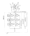
- FIG. 2 is a circuit diagram illustrating a brushless motor and a control device in an embodiment of the invention
- FIG. 3 is a diagram illustrating an energization pattern of the brushless motor and detection conditions of a demagnetization failure in an embodiment of the invention
- FIG. 4 is a diagram illustrating a voltage of a non-energized phase of the brushless motor in an embodiment of the invention
- FIG. 5 is a diagram illustrating changes in pulse induced voltage due to a demagnetization failure of the brushless motor in an embodiment of the invention.
- FIG. 6 is a flowchart illustrating processing in a case in which the demagnetization failure occurs in the brushless motor in an embodiment of the invention
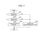
- FIG. 7 is a flowchart illustrating detection processing of a failure of the brushless motor in an embodiment of the invention.
- FIG. 8 is a diagram illustrating the detection conditions of the demagnetization failure of the brushless motor in an embodiment of the invention.
- FIG. 9 is a flowchart illustrating processing of measuring the pulse induced voltage at an angle of switching energized phases in an embodiment of the invention.
- FIG. 10 is a flowchart illustrating processing of measuring the pulse induced voltage at the angle where switching of the energized phases are performed in an embodiment of the invention.
- FIG. 11 is a flowchart illustrating processing performed in a case in which the demagnetization failure occurs in the brushless motor of an embodiment of the invention.
- FIG. 1 is a block diagram illustrating a hydraulic pump system, which is an example in which a drive device for a brushless motor according to an embodiment of the invention is applied thereto.
- This hydraulic pump system is a system for circulating oil in a vehicle automatic transmission.
- the hydraulic pump system illustrated in FIG. 1 includes a mechanical oil pump 6 driven by an output of an engine (not shown) and a motor-driven electric oil pump 1 , serving as oil pumps for supplying the oil to a transmission 7 and an actuator 8 .
- Electric oil pump 1 operates, for example, when the engine is stopped due to an idle reduction, and thereby supplies the oil to transmission 7 and actuator 8 to suppress a decrease in an oil pressure during the idle reduction.
- Electric oil pump 1 is driven by a three-phase brushless motor 2 directly coupled thereto, and brushless motor 2 is controlled by a motor control device 3 based on a command provided from an AT control device 4 .
- Motor control device 3 is a drive device that controls energization of each phase of brushless motor 2 .
- Electric oil pump 1 driven by brushless motor 2 supplies the oil in an oil pan 10 to transmission 7 and actuator 8 through an oil piping 5 .
- AT control device 4 sends a motor startup command to motor control device 3 in response to a stop command of the engine due to the idle reduction.
- motor control device 3 Upon reception of the motor startup command, motor control device 3 starts up brushless motor 2 to rotate electric oil pump 1 , and thereby starts oil supply under pressure by electric oil pump 1 .
- check valve 11 opens, so that oil circulates through a route of oil piping 5 , electric oil pump 1 , check valve 11 , transmission 7 , actuator 8 and oil pan 10 .
- the brushless motor which is driven by the drive device according to the invention, may be, for example, a brushless motor which drives an electric water pump used for circulating cooling water for an engine in a hybrid vehicle and others, and the equipment driven by the brushless motor is not limited to the oil pump.
- the brushless motor is not limited to the motor mounted on the vehicle.
- FIG. 2 is a circuit diagram illustrating, by way of example, brushless motor 2 and control device 3 .
- Control device 3 includes a drive circuit 212 and a controller 213 provided with a microcomputer. Controller 213 performs communications with AT control device 4 through a communication line (not shown).
- Brushless motor 2 is a three-phase DC brushless motor, which includes three-phase coils 215 u , 215 v and 215 w of U-, V- and W-phases on a cylindrical stator (not shown) and includes a permanent magnet rotator 216 that is rotatable in a space formed in a central of the stator.
- Drive circuit 212 has a circuit including a three-phase bridge-connected switching elements 217 a - 217 f including antiparallel diodes 218 a - 218 f , respectively, and also has a power supply circuit 219 , and switching elements 217 a - 217 f are formed of, e.g., FETs, respectively.
- Switching elements 217 a - 217 f have gate terminals connected to controller 213 , and controller 213 controls the ON and OFF of switching elements 217 a - 217 f by pulse width modulation PWM.
- Controller 213 performs the drive control of brushless motor 2 in a sensor-less manner, in which a sensor obtaining position information about the rotator is not used, and further performs switching between sine wave drive and rectangular wave drive according to a motor rotation speed.
- the sine wave drive is a manner of driving brushless motor 2 by adding a sine wave voltage to each phase.
- the position information of the rotator is derived from the induced voltage (speed electromotive voltage) generated by the rotation of the rotator.
- the rotator position is estimated based on the motor rotation speed.
- a three-phase output value is calculated from the estimated rotator position and a PWM duty, so that the direction and the intensity of electric current is controlled according to a phase-to-phase difference in voltage, to thereby allow a three-phase alternating current to flow.
- the rectangular wave drive is a manner of driving brushless motor 2 by successively switching, according to a predetermined switching timing, energization patterns in which the two phases to be applied with the pulse voltage are selected from the three phases of brushless motor 2 .
- controller 213 obtains the position information of the rotator from the pulse induced voltage that is the voltage induced in the non-energized phase by the application of the pulse-like voltages to the energized phases, and thereby detects the timing in switching of the two phases to be applied with the pulse voltage selected from the three phases of brushless motor 2 .
- it detects the switching timing of the energization patterns.
- an output level of the speed electromotive voltage measured for the position detection in the sine wave drive decreases as the motor rotation speed decreases, and therefore the accuracy of the position detection based on the speed electromotive voltage is decreased in the region of a low rotation speed.
- the pulse induced voltage to be measured for the position detection in the rectangular wave drive keeps a sufficient output level and allows detection of the position information based on the pulse induced voltage even in the region of the low rotation speed including the motor-stopped state.
- controller 213 drives brushless motor 2 by the sine wave drive in the region of a high rotation speed in which the sine wave drive allows detection of the position information with a sufficient accuracy, and drives brushless motor 2 by the rectangular wave drive in the region of the low rotation speed in which the sine wave drive does not allow detection of the position information with a sufficient accuracy.
- a voltage threshold for deciding the timing of switching to a next energization pattern is set for each energization pattern.
- Controller 213 detects, as the switching timing of the energization patterns, a timing at which the pulse induced voltage induced in the non-energized phase exceeds the voltage threshold, and switches the energization to the next energization pattern when it detects the switching timing.
- controller 213 sets, in advance, a pulse induced voltage at a switching angle of the energization patterns as the voltage threshold, and detects that the angle of brushless motor 2 is the switching angle of the energization pattern when the pulse induced voltage reaches the voltage threshold.
- energization patterns (1)-(6) are set as the energization patterns.
- the current flows from the U-phase to the V-phase.
- the current flows from the U-phase to the W-phase.
- the current flows from the V-phase to the W-phase.
- the current flows from the V-phase to the U-phase.
- the current flows from the W-phase to the U-phase.
- the energization pattern (6) the current flows from the W-phase to the V-phase. Controller 213 successively switches the energization patterns every electric angle of 60 degrees.
- the W-phase becomes the non-energized phase in the energization pattern (1)
- the V-phase becomes the non-energized phase in the energization pattern (2)
- the U-phase becomes the non-energized phase in the energization pattern (3)
- the W-phase becomes the non-energized phase in the energization pattern (4)
- the V-phase becomes the non-energized phase in the energization pattern (5)
- the U-phase becomes the non-energized phase in the energization pattern (6).
- the angular position of the U-phase coil is the position of the rotator at the angle of 0 degrees
- the angular position of the rotator at which the switching from the energization pattern (3) to the energization pattern (4) is performed is set to 30 degrees
- the angular position of the rotator at which the switching from the energization pattern (4) to the energization pattern (5) is performed is set to 90 degrees
- the angular position of the rotator at which the switching from the energization pattern (5) to the energization pattern (6) is performed is set to 150 degrees
- the angular position of the rotator at which the switching from the energization pattern (6) to the energization pattern (1) is performed is set to 210 degrees
- the angular position of the rotator at which the switching from the energization pattern (1) to the energization pattern (2) is performed is set to 270 degrees
- Controller 213 detects the switching timing of the energization patterns switching every 60 degrees described above based on a comparison between the pulse induced voltage in the non-energized phase and the voltage threshold.
- the voltage threshold is set to a value higher or lower than a neutral point voltage as illustrated in FIG. 4 .
- the voltage threshold is set to a value lower than the neutral point voltage. Controller 213 performs the switching to the next energization pattern when the voltage of the non-energized phase becomes lower than the voltage threshold lower than the neutral point voltage.
- the voltage threshold is set to a value higher than the neutral point voltage. Controller 213 performs the switching to the next energization pattern when the voltage of the non-energized phase becomes higher than the voltage threshold higher than the neutral point voltage.
- controller 213 switches the energization patterns based on the comparison of the pulse induced voltage of the non-energized phase with the voltage threshold. Therefore, when the demagnetization failure which decreases a magnetic flux occurs under high-temperature conditions or the like, and the pulse induced voltage of the non-energized phase decreases and does not reach the voltage threshold, e.g., as illustrated in FIG. 5 , controller 213 cannot detect the switching timing of the energization patterns, and cannot startup brushless motor 2 .
- the energization is performed according to the energization pattern (3).
- controller 213 measures that the pulse induced voltage induced in the non-energized phase, i.e., the U-phase, becomes lower than the voltage threshold that is set as the voltage lower than the neutral point voltage, controller 213 performs the switching to the energization pattern (4).
- controller 213 can no longer detect the timing of switching to the energization pattern (4) and therefore maintains the energization pattern (3) so that brushless motor 2 cannot be started up.
- controller 213 controls brushless motor 2 as illustrated in a flowchart of FIG. 6 .
- controller 213 determines in step S 101 whether the energization of the respective phases of brushless motor 2 is being performed by the rectangular wave drive for generating a motor toque, or not.
- controller 213 determines in step S 101 that brushless motor 2 is being controlled, the operation proceeds to step S 102 , and controller 213 determines whether a duration time of a state in which the pulse induced voltage of the non-energized phase has not reached the voltage threshold set for each energization pattern is equal to or greater than the set time or not.
- controller 213 determines whether such an abnormal state, in which the energization pattern has continued for a time which cannot be attained in the normal state, has occurred or not.
- controller 213 When the switching of the energization patterns is in a state in which the switching is successively performed at time periods which is within the normal range, i.e., when the energization control by the rectangular wave drive is normal, the operation of controller 213 proceeds to step S 103 .
- controller 213 determines in step S 102 that the normal startup is already performed, and the operation proceeds to step S 103 .
- step S 103 controller 213 drives brushless motor 2 by the rectangular wave drive or the sine wave drive.
- controller 213 determines that the duration time of the state in which the pulse induced voltage of the non-energized phase has not reached the voltage threshold set for each energization pattern is equal to or greater than the set time, i.e., when the operation is in the abnormal state in which the energization pattern cannot be switched and therefore brushless motor 2 cannot be started up correctly, the operation proceeds to step S 104 .
- step S 104 controller 213 drives brushless motor 2 to the angular position where the energization patterns are switched, and measures the pulse induced voltage of the non-energized phase at the angular position where the energization pattern is switched, and then performs, for each energization pattern, the processing of learning the voltage threshold for updating the voltage threshold used for detection of the switching timing of the energization patterns based on the measured pulse induced voltages.
- step S 104 controller 213 learns six voltage thresholds used for the six energization patterns, respectively.
- controller 213 executes the processing of determining whether the abnormal state is caused by the demagnetization failure or a failure other than the demagnetization failure.
- the demagnetization failure is a state in which a magnetic flux of the brushless motor has decreased due to heat or the like, and the failure other than the demagnetization failure is, e.g., an immovable state caused by the lock of the rotator or the output shaft of brushless motor 2 or the like.
- controller 213 selects between continuation and stop of the control of brushless motor 2 , depending on whether the failure is the demagnetization failure or a failure other than the demagnetization failure.
- controller 213 changes the voltage threshold used for detecting the switching timing of the energization patterns to a value corresponding to the decreased pulse induced voltage, the energization patterns can be switched based on the comparison between the voltage threshold and the pulse induced voltage, and thereby brushless motor 2 can be started up.
- the energization patterns cannot be switched correctly even when the voltage threshold is changed, and therefore controller 213 stops the control of brushless motor 2 .
- controller 213 performs the determination of step S 105 as to whether the failure is the demagnetization failure or not.
- step S 201 controller 213 determines whether the voltage threshold learned in step S 104 satisfies a condition (0) or not.
- the voltage thresholds in the energization patterns (1), (3) and (5) are set to a value lower than the neutral point voltage
- the voltage thresholds in the energization patterns (2), (4) and (6) are set to a value higher than the neutral point voltage.
- the pulse induced voltage at the switching timing of the energization patterns holds the state lower than the neutral point voltage in the energization patterns (1), (3) and (5), and holds the state higher than the neutral point voltage in the energization patterns (2), (4) and (6).
- the pulse induced voltage of the non-energized phase that is, the U-phase
- the pulse induced voltage of the non-energized phase that is, the W-phase
- the pulse induced voltage of the non-energized phase holds the voltage higher than that at the neutral point, and does not satisfy the conditions that the pulse induced voltage at the timing of switching to the energization pattern (2) in the energization pattern (1) is lower than the neutral point voltage.
- controller 213 determines that the demagnetization failure lowers the pulse induced voltage and consequently the detection of the switching timing of the energization patterns becomes impossible.
- the state satisfying the condition (1) is a state in which all the six newly learned voltage thresholds keep the states higher or lower than the neutral point voltage without changing from the initial state, as illustrated in FIG. 3 .
- controller 213 determines that brushless motor 2 cannot be started up due to a failure such as a lock failure other than the demagnetization failure, and the operation proceeds to step S 203 , in which controller 213 determines the occurrence of the failure other than the demagnetization failure.
- the state in which the voltage threshold is higher or lower than the neutral point voltage is a state in which the voltage threshold falls within a voltage range higher than the neutral point voltage, or does not fall within a voltage range lower than the neutral point voltage.
- Controller 213 may determine whether the condition (1) is satisfied or not, based on the pulse induced voltage measured at the angle of switching the energization patterns, instead of the voltage threshold.
- controller 213 may perform the determination whether the condition (1) is satisfied or not, based on whether the measured pulse induced voltage or the voltage threshold set based on the measured pulse induced voltage is positive or negative in value.
- controller 213 determines in step S 201 that all the six voltage thresholds have held the states higher or lower than the neutral point voltage without changing from the initial states, controller 213 can determine that the demagnetization failure has occurred. However, the operation of controller 213 further proceeds to step S 202 , and controller 213 determines whether the voltage threshold learned in step S 104 satisfies the condition (2) or not.
- the condition (2) is a condition in which it is determined whether the pulse induced voltage has actually lowered or not, while satisfying the condition (1). As illustrated in FIG. 8 , the condition (2) requires that all the voltage thresholds learned in step S 104 fall within the voltage range defined between the initial value of the voltage threshold and the neutral point voltage.
- the pulse induced voltage decreases. Therefore, even if the six voltage thresholds satisfy the condition (1), there is a possibility that the failure other than the demagnetization failure has occurred when the newly learned voltage threshold is greater than the initial values in the energization pattern (2), (4) or (6), and when it is less than the initial value in the energization pattern (1), (3) or (5).
- step S 104 when all the voltage thresholds learned in step S 104 fall within the voltage range defined between the initial value of the voltage threshold and the neutral point voltage and the condition (2) is satisfied, it is confirmed that the demagnetization failure has occurred.
- controller 213 determines that the failure other than the demagnetization failure has occurred.
- controller 213 determines that the demagnetization failure has occurred.
- Step S 202 may be omitted, and controller 213 may determine whether the failure occurring in the present state is the demagnetization failure or the failure other than the demagnetization failure, based on the determination whether the condition (1) is satisfied or not in step S 201 .
- step S 201 may be omitted, and controller 213 may determine whether the failure occurring in the present state is the demagnetization failure or the failure other than the demagnetization failure, based on the determination whether the condition (2) is satisfied or not in step S 202 .
- the voltage threshold to be compared with the newly learned voltage threshold is not limited to the initial value, and controller 213 may compare the newly learned voltage threshold with, for example, the previous learned value, a moving average value of the learned values or the like.
- Controller 213 may determine whether the failure is the demagnetization failure or not, based on a comparison between the voltage threshold learned in a state where the normal energization control cannot be performed and the voltage range set as the normal range or the abnormal range.
- controller 213 After controller 213 performs, in step S 105 of the flowchart in FIG. 6 , the determination whether the demagnetization failure has occurred or the failure other than the demagnetization failure has occurred, controller 213 determines in step S 106 whether the occurrence of the demagnetization failure was determined in the process of step S 105 or not.
- controller 213 proceeds to step S 107 , in which controller 213 stops the energization of brushless motor 2 to keep brushless motor 2 in the stopped state, and notifies AT control device 4 and others, of the fact that the driving of brushless motor 2 has been stopped due to occurrence of the lock failure or the like other than the demagnetization failure in brushless motor 2 .
- AT control device 4 When AT control device 4 receives the signal indicative of the occurrence of the lock failure or the like other than the demagnetization failure in brushless motor 2 , AT control device 4 performs processing, such as outputting a signal requesting prohibition of the idle reduction, outputting a control signal operating a warning device to issue a warning about the failure occurrence in brushless motor 2 , storing a determination history of the lock failure, and the like.
- step S 106 determines in step S 106 that the demagnetization failure has occurred
- step S 108 controller 213 performs processing to use the newly learned voltage threshold as the voltage threshold used for controlling the switching of the energization patterns.
- controller 213 performs the processing of changing the voltage threshold to the value which is exceeded by the pulse induced voltage decreased due to the demagnetization failure, when the angle of switching the energization pattern is attained.
- the voltage threshold approaches the neutral point voltage.
- controller 213 When controller 213 performs the processing of changing the voltage threshold in step S 108 , controller 213 sets, in the next step S 109 , a flag indicating that the occurrence of the demagnetization failure is detected.
- controller 213 continues the control of brushless motor 2 , using the voltage threshold changed in step S 108 , and further notifies AT control device 4 and others of the fact that the demagnetization failure has occurred.
- AT control device 4 When AT control device 4 receives the signal indicative of the occurrence of the demagnetization failure in brushless motor 2 , AT control device 4 performs processing, such as outputting a signal requesting the change in execution conditions of the idle reduction, outputting the control signal that operates the warning device to issue a warning about the failure occurrence in brushless motor 2 , and storing a determination history of the demagnetization failure.
- the causes of the abnormality are divided into the demagnetization failure and others in the abnormal state in which the switching control of the energization patterns cannot be performed based on the pulse induced voltage.
- controller 213 changes the voltage threshold and continues the control.
- controller 213 stops the control of brushless motor 2 .
- step S 104 of the flowchart of FIG. 6 will be described in detail.
- FIG. 9 illustrates an example of the learning processing of the voltage threshold executed by controller 213 .
- step S 301 controller 213 determines whether or not the learning of the voltage threshold is to be started because the energization patterns of brushless motor 2 cannot be switched.
- step S 301 When controller 213 determines the start of the learning in step S 301 , the operation proceeds to step S 302 , in which controller 213 sets an initial energization pattern and energizes each phase of brushless motor 2 according to the set energization pattern.
- controller 213 may set the energization pattern that was set when the abnormality of the control was determined, may set a energization pattern that is advanced by a predetermined number of times from the energization pattern that was set when the abnormality in the control was determined, and further may set a predetermined energization pattern.
- controller 213 bypasses step S 302 and proceeds to step S 303 .
- Controller 213 determines, in step S 303 , whether the pulse induced voltage of the non-energized phase in the energization pattern at that time is already obtained or not. When the pulse induced voltage is not yet obtained, the operation proceeds to step S 304 . When the pulse induced voltage is already obtained, the operation of controller 213 proceeds to step S 305 .
- step S 304 controller 213 determines whether a predetermined time ( 1 ) or more has elapsed since the switching of the energization patterns, or not.
- the operation of controller 213 proceeds to step S 307 .
- the operation proceeds to step S 305 .
- the predetermined time ( 1 ) is a delay time from the switching of the energization patterns to the measurement of the pulse induced voltage at the angle at which the energization patterns are switched.
- the predetermined time ( 1 ) is set to avoid a fluctuation period of the voltage of the non-energized phase immediately after the switching of the energization patterns.
- controller 213 proceeds to step S 305 regardless of elapsing and non-elapsing of the predetermined time ( 1 ).
- step S 305 it is determined whether the time elapsed since setting of the energization pattern at that time has reached a predetermined time ( 2 ) or not.
- the predetermined time ( 2 ) is a response time required before the actual motor angle becomes stable after reaching the angle corresponding to the energization pattern at that time.
- the predetermined time ( 2 ) is set such that when the predetermined time ( 2 ) has elapsed after the switching of the energization patterns, it can be regarded that brushless motor 2 has rotated to and stopped at the angle corresponding to the energization pattern at that time.
- the predetermined time ( 1 ) is shorter than the predetermined time ( 2 ).
- controller 213 terminates the routine, so that the energization with the energization pattern at that time further continues.
- the operation of controller 213 proceeds to step S 306 , in which controller 213 performs the switching to the next energization pattern.
- step S 304 When controller 213 switches the energization patterns, the operation proceeds from step S 304 to step S 307 after elapsing of the predetermined time ( 1 ).
- step S 307 controller 213 samples the voltage of the non-energized phase of the energization pattern at that time, as the pulse induced voltage at the angle at which the energization patterns are switched.
- brushless motor 2 can be positioned in the position of 90 degrees that is the angle of switching from the energization pattern (4) to the energization pattern (5).
- a voltage Vw of the W-phase immediately after the switching becomes a voltage of the non-energized phase at the angle of 90 degrees.
- the voltage threshold it is possible to set the voltage threshold to be used for detecting the angle of 90 degrees, that is, the timing of switching from the energization pattern (4) to the energization pattern (5).
- Controller 213 continues the energization in one energization pattern for the predetermined time ( 2 ), and then switches the energization pattern to the next pattern.
- the voltage of the non-energized phase appearing when the predetermined time ( 1 ) elapses after the switching is measured as the voltage of the non-energized phase at the switching timing of the energization patterns, and controller 213 repeats such measurement, and thereby learns the voltage thresholds corresponding to the respective energization patterns.
- Controller 213 may use the pulse induced voltage sampled in step S 307 as the voltage threshold as it is, and further may calculate the voltage threshold using the pulse induced voltage sampled in step S 307 as a variable.
- Controller 213 determines in step S 308 whether the voltage thresholds in all the energization patterns are learned or not. When the voltage thresholds in all the energization patterns are not learned, the operation returns to step S 301 to continue the learning of the voltage threshold.
- controller 213 learns the voltage thresholds in all the energization patterns, the operation proceeds to step S 309 , in which controller 213 determines the completion of the learning.
- the method of measuring the pulse induced voltage according to the timing of switching of the energization patterns is not limited to the above, and various known measuring methods may be appropriately employed.
- a flowchart of FIG. 10 illustrates an example of the learning processing which is configured to switch duty cycles in the PWM control of brushless motor 2 corresponding to a case in which the positioning is performed and a case in which the voltage is sampled according to the switching timing of the energization patterns.
- controller 213 proceeds to step S 302 A after step S 302 , in which the initial energization pattern is set, and controller 213 sets the duty cycle in the PWM control of brushless motor 2 to a duty cycle D 1 used for positioning brushless motor 2 by rotating brushless motor 2 .
- controller 213 determines in step S 308 that the learning of all the energization patterns is not completed, the operation proceeds to step S 308 A, and controller 213 sets the duty cycle in the PWM control of brushless motor 2 to the foregoing duty cycle D 1 .
- Duty cycle D 1 set in step S 302 A may be equal in value to duty cycle D 1 set in step S 308 A, and also may be different therefrom.
- controller 213 determines, in step S 305 , the elapsing of the predetermined time ( 2 ) in the control state with duty cycle D 1 , controller 213 prepares for the learning of the voltage threshold, and sets in step S 306 A the duty cycle in the PWM control of brushless motor 2 to a duty cycle D 2 smaller than the duty cycle D 1 .
- Controller 213 waits for elapsing of the predetermined time ( 1 ) in the control state with the duty cycle D 2 .
- controller 213 learns the voltage at that time of the non-energized phase as the pulse induced voltage at the switching angle of the energization pattern, and samples the voltage, and then sets the duty cycle back from the duty cycle D 2 to the duty cycle D 1 .
- brushless motor 2 cannot be rotated to a predetermined position corresponding to the energization pattern when the duty cycle is low at the time of positioning brushless motor 2 , and thereby erroneous learning of the voltage threshold might occur.
- the voltage induced in the non-energized phase increases as the duty cycle increases. Therefore, when the voltage threshold is learned based on the pulse induced voltage sampled in the state in which the duty cycle is high, the pulse induced voltage may not reach the voltage threshold in a state in which the duty cycle is low and thus the pulse induced voltage is decreased. Accordingly, it may be impossible to detect the timing of switching of the energization patterns.
- the voltage threshold that can be applied even in the state of the low duty cycle is set based on the voltage that is sampled in the state of the high duty cycle, the learning error of the voltage threshold increases, and accordingly, it may be impossible to switch the energization patterns according to the appropriate timing.
- controller 213 positions brushless motor 2 , that is, when controller 213 rotates brushless motor 2 to the switching angle of the energization pattern, controller 213 sets the duty cycle D 1 allowing the rotation of brushless motor 2 even at a low temperature. Also, when the voltage of the non-energized phase is sampled at the switching angle, controller 213 sets the duty cycle D 2 (D 2 ⁇ D 1 ) lower than that at the time of positioning, which allows the learning of the voltage threshold with sufficiently high accuracy.
- the duty cycle D 1 is used for ensuring the motor torque in the low temperature state, and therefore the necessity of employing the duty cycle D 1 in the high temperature state is low. Accordingly, controller 213 may set the duty cycle D 1 to a greater value as the oil temperature decreases, and may cancel the switching of the duty cycles when the oil temperature exceeds a set temperature.
- a flowchart of FIG. 11 illustrates another example of the control in a case in which the demagnetization failure occurs.
- steps performing the substantially same processing as those in the flowchart of FIG. 6 bear the same step numbers, and detailed description thereof is omitted.
- step S 102 when controller 213 determines in step S 102 that a state in which the pulse induced voltage of the non-energized phase has not reached the threshold set for each energization pattern has continued for a set time or more, the operation proceeds to step S 102 A, in which controller 213 determines whether a history of detecting the demagnetization failure is present or not.
- controller 213 proceeds to step S 107 without learning the voltage threshold, and controller 213 stops the energization of brushless motor 2 to stop the rotation of brushless motor 2 .
- controller 213 may learn the voltage threshold again. When the learned voltage threshold is small and deviates from an allowed range, controller 213 may determine that the demagnetization failure has advanced beyond the allowed range, and may stop the energization control of brushless motor 2 .
- controller 213 determines in step S 102 that the switching of the energization patterns was performed, based on the comparison between the pulse induced voltage of the non-energized phase and the voltage threshold, the operation proceeds to step S 103 A, in which controller 213 determines whether the history of detecting the demagnetization failure is present or not.
- controller 213 determines in step S 103 A that the history of detecting the demagnetization failure is present, that is, when controller 213 continues the control of brushless motor 2 after changing the voltage threshold according to the decrease in the pulse induced voltage due to the demagnetization failure, the operation of controller 213 proceeds to step S 103 B.
- step S 103 B controller 213 restricts the motor current of brushless motor 2 to be less than that in a case in which the demagnetization failure has not occurred, and continues the control of brushless motor 2 .
- controller 213 sets the allowed motor current that is less than a motor current allowed when the demagnetization failure has not occurred, and controls the motor current not to exceed this allowed motor current.
- controller 213 When the history of detecting the demagnetization failure is not present, i.e., when the demagnetization failure has not occurred, the operation of controller 213 proceeds to step S 103 , in which controller 213 controls brushless motor 2 without performing the processing of suppressing the motor current to be less than the standard.
- Controller 213 can estimate that the demagnetization has advanced as the pulse induced voltage decreases, and controller 213 can change and lower the allowed motor current as the demagnetization advances to a further extent.
Applications Claiming Priority (2)
| Application Number | Priority Date | Filing Date | Title |
|---|---|---|---|
| JP2013021212A JP6030466B2 (ja) | 2013-02-06 | 2013-02-06 | ブラシレスモータの駆動装置 |
| JP2013-021212 | 2013-02-06 |
Publications (2)
| Publication Number | Publication Date |
|---|---|
| US20140217936A1 US20140217936A1 (en) | 2014-08-07 |
| US9236818B2 true US9236818B2 (en) | 2016-01-12 |
Family
ID=51206141
Family Applications (1)
| Application Number | Title | Priority Date | Filing Date |
|---|---|---|---|
| US14/037,858 Active 2034-04-01 US9236818B2 (en) | 2013-02-06 | 2013-09-26 | Drive device and drive method for brushless motor |
Country Status (4)
| Country | Link |
|---|---|
| US (1) | US9236818B2 (ja) |
| JP (1) | JP6030466B2 (ja) |
| CN (1) | CN103973177A (ja) |
| DE (1) | DE102013218049A1 (ja) |
Cited By (1)
| Publication number | Priority date | Publication date | Assignee | Title |
|---|---|---|---|---|
| US11396723B2 (en) | 2017-12-22 | 2022-07-26 | Samsung Electronics Co., Ltd. | Washing machine and control method of the same |
Families Citing this family (9)
| Publication number | Priority date | Publication date | Assignee | Title |
|---|---|---|---|---|
| KR20160028251A (ko) * | 2014-09-03 | 2016-03-11 | 주식회사 코아비스 | Bldc 모터 제어 시스템 및 그 제어 방법 |
| JP6457410B2 (ja) | 2016-01-12 | 2019-01-23 | 日立オートモティブシステムズ株式会社 | 3相ブラシレスモータの駆動装置及びその駆動方法 |
| JP2017127041A (ja) * | 2016-01-12 | 2017-07-20 | 日立アプライアンス株式会社 | モータ異常検出システム及びこれを備えた機器 |
| JP6661509B2 (ja) * | 2016-10-04 | 2020-03-11 | 日立オートモティブシステムズ株式会社 | ブラシレスモータの制御装置及び制御方法 |
| JP6815282B2 (ja) * | 2017-06-02 | 2021-01-20 | 三菱パワー株式会社 | 回転電機の特徴量評価システムおよび回転電機の特徴量評価方法 |
| JP6324600B1 (ja) * | 2017-07-06 | 2018-05-16 | 北斗制御株式会社 | 電動機の界磁位置検出方法 |
| DE102017009512A1 (de) * | 2017-10-12 | 2019-04-18 | NIDEX driveXpert GmbH | Verfahren zum Starten und Betreiben eines BLDC-Motors und BLDC-Motor |
| WO2019124985A1 (en) | 2017-12-20 | 2019-06-27 | Samsung Electronics Co., Ltd. | Motor and washing machine having the same |
| JP7063008B2 (ja) * | 2018-02-28 | 2022-05-09 | 株式会社デンソー | 磁極位置推定装置 |
Citations (5)
| Publication number | Priority date | Publication date | Assignee | Title |
|---|---|---|---|---|
| US20060186846A1 (en) * | 2005-02-18 | 2006-08-24 | Lassen Jacob L | Sensorless control of two-phase brushless DC motor |
| US20070194731A1 (en) * | 2006-02-20 | 2007-08-23 | Matsushita Electric Industrial Co., Ltd. | Motor drive method |
| US20090079374A1 (en) * | 2005-01-07 | 2009-03-26 | Ronald De Four | Self Starting Method and an Apparatus for Sensorless Commutation of Brushless Dc Motors |
| US20090200971A1 (en) | 2008-02-07 | 2009-08-13 | Yoshitaka Iwaji | Drive system of synchronous motor |
| US20110234133A1 (en) * | 2010-03-23 | 2011-09-29 | Hitachi Automotive Systems, Ltd. | Brushless motor drive apparatus and drive method |
Family Cites Families (4)
| Publication number | Priority date | Publication date | Assignee | Title |
|---|---|---|---|---|
| JPH05236788A (ja) * | 1992-02-19 | 1993-09-10 | Matsushita Electric Ind Co Ltd | ブラシレスモータの駆動装置 |
| JP2003111480A (ja) * | 2001-09-28 | 2003-04-11 | Matsushita Electric Ind Co Ltd | 電動機駆動装置 |
| JP2011200058A (ja) * | 2010-03-23 | 2011-10-06 | Hitachi Automotive Systems Ltd | ブラシレスモータの駆動装置 |
| JP5525490B2 (ja) | 2011-07-13 | 2014-06-18 | 富士通フロンテック株式会社 | クレードル |
-
2013
- 2013-02-06 JP JP2013021212A patent/JP6030466B2/ja active Active
- 2013-09-03 CN CN201310394751.1A patent/CN103973177A/zh active Pending
- 2013-09-10 DE DE102013218049.7A patent/DE102013218049A1/de not_active Withdrawn
- 2013-09-26 US US14/037,858 patent/US9236818B2/en active Active
Patent Citations (7)
| Publication number | Priority date | Publication date | Assignee | Title |
|---|---|---|---|---|
| US20090079374A1 (en) * | 2005-01-07 | 2009-03-26 | Ronald De Four | Self Starting Method and an Apparatus for Sensorless Commutation of Brushless Dc Motors |
| US20060186846A1 (en) * | 2005-02-18 | 2006-08-24 | Lassen Jacob L | Sensorless control of two-phase brushless DC motor |
| US20070194731A1 (en) * | 2006-02-20 | 2007-08-23 | Matsushita Electric Industrial Co., Ltd. | Motor drive method |
| US20090200971A1 (en) | 2008-02-07 | 2009-08-13 | Yoshitaka Iwaji | Drive system of synchronous motor |
| JP2009189176A (ja) | 2008-02-07 | 2009-08-20 | Renesas Technology Corp | 同期電動機の駆動システム |
| US8258732B2 (en) | 2008-02-07 | 2012-09-04 | Renesas Electronics Corporation | Drive system of synchronous motor |
| US20110234133A1 (en) * | 2010-03-23 | 2011-09-29 | Hitachi Automotive Systems, Ltd. | Brushless motor drive apparatus and drive method |
Cited By (1)
| Publication number | Priority date | Publication date | Assignee | Title |
|---|---|---|---|---|
| US11396723B2 (en) | 2017-12-22 | 2022-07-26 | Samsung Electronics Co., Ltd. | Washing machine and control method of the same |
Also Published As
| Publication number | Publication date |
|---|---|
| US20140217936A1 (en) | 2014-08-07 |
| JP2014155273A (ja) | 2014-08-25 |
| JP6030466B2 (ja) | 2016-11-24 |
| DE102013218049A1 (de) | 2014-08-07 |
| CN103973177A (zh) | 2014-08-06 |
Similar Documents
| Publication | Publication Date | Title |
|---|---|---|
| US9236818B2 (en) | Drive device and drive method for brushless motor | |
| JP5952502B2 (ja) | 3相ブラシレスモータの駆動装置 | |
| US8773060B2 (en) | Brushless motor drive device and drive method | |
| US8710788B2 (en) | Brushless motor drive apparatus and drive method | |
| US20150236626A1 (en) | Brushless motor control device and brushless motor system | |
| US10381965B2 (en) | Drive device and method for three-phase brushless motor | |
| EP2538545B1 (en) | Sensorless control unit for brushless DC motor | |
| US10447182B2 (en) | Control device and method for brushless motor | |
| US9882517B2 (en) | Method and system for controlling motor | |
| JP5561792B2 (ja) | ブラシレスモータの駆動装置 | |
| EP2541756B1 (en) | Sensorless control unit for brushless DC motor | |
| JP2011200058A (ja) | ブラシレスモータの駆動装置 | |
| JP6173107B2 (ja) | ブラシレスモータの駆動装置、及び駆動方法 | |
| JP6058449B2 (ja) | ブラシレスモータの駆動装置 | |
| JP6150647B2 (ja) | ブラシレスモータの制御装置 | |
| JP7404040B2 (ja) | モータ制御装置およびモータ制御装置の制御方法 | |
| JP2013183550A (ja) | ブラシレスモータの駆動装置 | |
| US20150249410A1 (en) | Control Device and Control Method for Brushless Motor | |
| JP7356599B2 (ja) | ブラシレスモータの制御装置及び制御方法 | |
| JP2009225590A (ja) | 電動機制御装置 | |
| JP2013252027A (ja) | 電動モータの制御装置 |
Legal Events
| Date | Code | Title | Description |
|---|---|---|---|
| AS | Assignment |
Owner name: HITACHI AUTOMOTIVE SYSTEMS, LTD., JAPAN Free format text: ASSIGNMENT OF ASSIGNORS INTEREST;ASSIGNOR:OKAMOTO, NAOKI;REEL/FRAME:031303/0986 Effective date: 20130829 |
|
| STCF | Information on status: patent grant |
Free format text: PATENTED CASE |
|
| MAFP | Maintenance fee payment |
Free format text: PAYMENT OF MAINTENANCE FEE, 4TH YEAR, LARGE ENTITY (ORIGINAL EVENT CODE: M1551); ENTITY STATUS OF PATENT OWNER: LARGE ENTITY Year of fee payment: 4 |
|
| AS | Assignment |
Owner name: HITACHI ASTEMO, LTD., JAPAN Free format text: CHANGE OF NAME;ASSIGNOR:HITACHI AUTOMOTIVE SYSTEMS, LTD.;REEL/FRAME:056299/0447 Effective date: 20210101 |
|
| MAFP | Maintenance fee payment |
Free format text: PAYMENT OF MAINTENANCE FEE, 8TH YEAR, LARGE ENTITY (ORIGINAL EVENT CODE: M1552); ENTITY STATUS OF PATENT OWNER: LARGE ENTITY Year of fee payment: 8 |