US9173291B2 - Circuit board and method for manufacturing the same - Google Patents
Circuit board and method for manufacturing the same Download PDFInfo
- Publication number
- US9173291B2 US9173291B2 US14/060,345 US201314060345A US9173291B2 US 9173291 B2 US9173291 B2 US 9173291B2 US 201314060345 A US201314060345 A US 201314060345A US 9173291 B2 US9173291 B2 US 9173291B2
- Authority
- US
- United States
- Prior art keywords
- insulating layer
- etch stop
- circuit board
- stop pattern
- interlayer insulating
- Prior art date
- Legal status (The legal status is an assumption and is not a legal conclusion. Google has not performed a legal analysis and makes no representation as to the accuracy of the status listed.)
- Active, expires
Links
Images


Classifications
-
- H—ELECTRICITY
- H01—ELECTRIC ELEMENTS
- H01L—SEMICONDUCTOR DEVICES NOT COVERED BY CLASS H10
- H01L24/00—Arrangements for connecting or disconnecting semiconductor or solid-state bodies; Methods or apparatus related thereto
- H01L24/01—Means for bonding being attached to, or being formed on, the surface to be connected, e.g. chip-to-package, die-attach, "first-level" interconnects; Manufacturing methods related thereto
- H01L24/18—High density interconnect [HDI] connectors; Manufacturing methods related thereto
- H01L24/23—Structure, shape, material or disposition of the high density interconnect connectors after the connecting process
- H01L24/24—Structure, shape, material or disposition of the high density interconnect connectors after the connecting process of an individual high density interconnect connector
-
- H—ELECTRICITY
- H05—ELECTRIC TECHNIQUES NOT OTHERWISE PROVIDED FOR
- H05K—PRINTED CIRCUITS; CASINGS OR CONSTRUCTIONAL DETAILS OF ELECTRIC APPARATUS; MANUFACTURE OF ASSEMBLAGES OF ELECTRICAL COMPONENTS
- H05K1/00—Printed circuits
- H05K1/02—Details
- H05K1/11—Printed elements for providing electric connections to or between printed circuits
- H05K1/115—Via connections; Lands around holes or via connections
- H05K1/116—Lands, clearance holes or other lay-out details concerning the surrounding of a via
-
- H—ELECTRICITY
- H05—ELECTRIC TECHNIQUES NOT OTHERWISE PROVIDED FOR
- H05K—PRINTED CIRCUITS; CASINGS OR CONSTRUCTIONAL DETAILS OF ELECTRIC APPARATUS; MANUFACTURE OF ASSEMBLAGES OF ELECTRICAL COMPONENTS
- H05K1/00—Printed circuits
- H05K1/02—Details
- H05K1/11—Printed elements for providing electric connections to or between printed circuits
- H05K1/111—Pads for surface mounting, e.g. lay-out
- H05K1/112—Pads for surface mounting, e.g. lay-out directly combined with via connections
- H05K1/113—Via provided in pad; Pad over filled via
-
- H—ELECTRICITY
- H05—ELECTRIC TECHNIQUES NOT OTHERWISE PROVIDED FOR
- H05K—PRINTED CIRCUITS; CASINGS OR CONSTRUCTIONAL DETAILS OF ELECTRIC APPARATUS; MANUFACTURE OF ASSEMBLAGES OF ELECTRICAL COMPONENTS
- H05K3/00—Apparatus or processes for manufacturing printed circuits
- H05K3/0011—Working of insulating substrates or insulating layers
- H05K3/0017—Etching of the substrate by chemical or physical means
-
- H—ELECTRICITY
- H05—ELECTRIC TECHNIQUES NOT OTHERWISE PROVIDED FOR
- H05K—PRINTED CIRCUITS; CASINGS OR CONSTRUCTIONAL DETAILS OF ELECTRIC APPARATUS; MANUFACTURE OF ASSEMBLAGES OF ELECTRICAL COMPONENTS
- H05K3/00—Apparatus or processes for manufacturing printed circuits
- H05K3/40—Forming printed elements for providing electric connections to or between printed circuits
- H05K3/42—Plated through-holes or plated via connections
- H05K3/421—Blind plated via connections
-
- H—ELECTRICITY
- H05—ELECTRIC TECHNIQUES NOT OTHERWISE PROVIDED FOR
- H05K—PRINTED CIRCUITS; CASINGS OR CONSTRUCTIONAL DETAILS OF ELECTRIC APPARATUS; MANUFACTURE OF ASSEMBLAGES OF ELECTRICAL COMPONENTS
- H05K2201/00—Indexing scheme relating to printed circuits covered by H05K1/00
- H05K2201/01—Dielectrics
- H05K2201/0183—Dielectric layers
- H05K2201/0195—Dielectric or adhesive layers comprising a plurality of layers, e.g. in a multilayer structure
-
- H—ELECTRICITY
- H05—ELECTRIC TECHNIQUES NOT OTHERWISE PROVIDED FOR
- H05K—PRINTED CIRCUITS; CASINGS OR CONSTRUCTIONAL DETAILS OF ELECTRIC APPARATUS; MANUFACTURE OF ASSEMBLAGES OF ELECTRICAL COMPONENTS
- H05K2201/00—Indexing scheme relating to printed circuits covered by H05K1/00
- H05K2201/09—Shape and layout
- H05K2201/09209—Shape and layout details of conductors
- H05K2201/095—Conductive through-holes or vias
- H05K2201/09563—Metal filled via
-
- H—ELECTRICITY
- H05—ELECTRIC TECHNIQUES NOT OTHERWISE PROVIDED FOR
- H05K—PRINTED CIRCUITS; CASINGS OR CONSTRUCTIONAL DETAILS OF ELECTRIC APPARATUS; MANUFACTURE OF ASSEMBLAGES OF ELECTRICAL COMPONENTS
- H05K2201/00—Indexing scheme relating to printed circuits covered by H05K1/00
- H05K2201/09—Shape and layout
- H05K2201/09818—Shape or layout details not covered by a single group of H05K2201/09009 - H05K2201/09809
- H05K2201/09854—Hole or via having special cross-section, e.g. elliptical
-
- H—ELECTRICITY
- H05—ELECTRIC TECHNIQUES NOT OTHERWISE PROVIDED FOR
- H05K—PRINTED CIRCUITS; CASINGS OR CONSTRUCTIONAL DETAILS OF ELECTRIC APPARATUS; MANUFACTURE OF ASSEMBLAGES OF ELECTRICAL COMPONENTS
- H05K2203/00—Indexing scheme relating to apparatus or processes for manufacturing printed circuits covered by H05K3/00
- H05K2203/07—Treatments involving liquids, e.g. plating, rinsing
- H05K2203/0703—Plating
- H05K2203/0733—Method for plating stud vias, i.e. massive vias formed by plating the bottom of a hole without plating on the walls
-
- H—ELECTRICITY
- H05—ELECTRIC TECHNIQUES NOT OTHERWISE PROVIDED FOR
- H05K—PRINTED CIRCUITS; CASINGS OR CONSTRUCTIONAL DETAILS OF ELECTRIC APPARATUS; MANUFACTURE OF ASSEMBLAGES OF ELECTRICAL COMPONENTS
- H05K3/00—Apparatus or processes for manufacturing printed circuits
- H05K3/0011—Working of insulating substrates or insulating layers
- H05K3/0017—Etching of the substrate by chemical or physical means
- H05K3/002—Etching of the substrate by chemical or physical means by liquid chemical etching
Definitions
- the present invention relates to a circuit board and a method for manufacturing the same, and more particularly, to a circuit board with a via structure which has a vertically perpendicular side surface and can implement a fine pitch, and a method for manufacturing the same.
- the levels of fine pitch required for a via structure applied to the recent package substrates and printed circuit boards are that the width of a via pad is less than 15 ⁇ m, the width of a via is less than 5 ⁇ m, and the interval between the vias is less than 30 ⁇ m.
- the conventional vias are usually formed to have an inclined side surface, there are limitations in reducing the interval between the vias.
- the conventional via forming techniques have difficulty in implementing an integrated via structure due to difficulty in forming a precise via hole.
- the thickness of the resist layer is greater than 2 ⁇ m, further greater than 10 ⁇ m, since it reaches the limits of resolution of a photolithography process, there is a demand for techniques that can form an integrated via structure regardless of the thickness of a resist layer.
- the present invention has been invented in order to overcome the above-described problems and it is, therefore, an object of the present invention to provide a circuit board with a fine-pitch via structure.
- a circuit board including: a base substrate; an interlayer insulating layer covering the base substrate; a via structure passing through at least the interlayer insulating layer of the base substrate and the interlayer insulating layer in the vertical direction; and an etch stop pattern disposed on the interlayer insulating layer in the horizontal direction perpendicular to the vertical direction to surround the via structure and made of an insulating material.
- the etch stop pattern may have a lower etch rate than the interlayer insulating layer.
- the via structure may include a through via passing through both of the base substrate and the interlayer insulating layer.
- the via structure may include a buried via passing through only the interlayer insulating layer.
- the via structure may include a via body passing through the interlayer insulating layer and a via pad connected to the via body on the interlayer insulating layer, wherein the via body and the via pad may be integrally formed by a single plating process.
- the interlayer insulating layer may include a first insulating layer covering the base substrate to surround a lower portion of the via structure and a second insulating layer covering the first insulating layer to surround an upper portion of the via structure, and the etch stop pattern may be interposed between the first insulating layer and the second insulating layer.
- the interlayer insulating layer may include a first insulating layer covering the base substrate to surround a lower portion of the via structure and a second insulating layer covering the first insulating layer to surround an upper portion of the via structure
- the etch stop pattern may include a first etch stop pattern interposed between the first insulating layer and the second insulating layer and a second etch stop pattern disposed on the second insulating layer and having an upper surface coplanar with an upper surface of the via structure.
- the interlayer insulating layer may include a first insulating layer covering the base substrate to surround a lower portion of the via structure and a second insulating layer covering the first insulating layer to surround an upper portion of the via structure
- the etch stop pattern may include a first etch stop pattern interposed between the first insulating layer and the second insulating layer
- the via structure may project higher than an upper surface of the second insulating layer.
- the interlayer insulating layer may include a first insulating layer covering the base substrate to surround a lower portion of the via structure and a second insulating layer covering the first insulating layer to surround an upper portion of the via structure, and the first insulating layer and the second insulating layer may be made of different photosensitive insulating materials.
- the interlayer insulating layer may include a first insulating layer covering the base substrate to surround a lower portion of the via structure and a second insulating layer covering the first insulating layer to surround an upper portion of the via structure, and the first insulating layer and the second insulating layer may be made of the same insulating material.
- the interlayer insulating layer may have a thickness of greater than 2 ⁇ m, and the via structure may have a vertically perpendicular side surface.
- a method for manufacturing a circuit board including the steps of: preparing a base substrate; forming a first insulating layer on the base substrate; forming an etch stop pattern on the first insulating layer with an insulating material; forming a second insulating layer on the etch stop pattern; performing an etching process for removing the second insulating layer and the first insulating layer by using the etch stop pattern as an etch stop layer to expose the base substrate; and performing a plating process by using the second insulating layer as a plating resist.
- the step of forming the etch stop pattern may include the step of coating a material having a lower etch rate than the first insulating layer and the second insulating layer on the first insulating layer.
- the step of performing the etching process may include the step of performing a reactive ion etching (RIE) process.
- RIE reactive ion etching
- the step of forming the second insulating layer may include the step of forming a photosensitive layer having different photosensitive properties from the first insulating layer on the etch stop pattern.
- the step of forming the second insulating layer may include the step of forming an insulating layer equal to the first insulating layer on the etch stop pattern.
- the method for manufacturing a circuit board may further include the step of performing a polishing process by using the second insulating layer as a polishing stop layer after the plating process.
- a circuit board including: a base substrate; an interlayer insulating layer covering the base substrate; a via structure passing through at least the interlayer insulating layer of the base substrate and the interlayer insulating layer in the vertical direction; and an etch stop pattern disposed inside the interlayer insulating layer in the horizontal direction perpendicular to the vertical direction to have a ring shape surrounding a side surface of the via structure and made of a conductive material.
- the etch stop pattern may have a lower etch rate than the interlayer insulating layer.
- the via structure may include a through via passing through both of the base substrate and the interlayer insulating layer.
- the via structure may include a buried via passing through only the interlayer insulating layer.
- the via structure may include a via body passing through the interlayer insulating layer and a via pad connected to the via body on the interlayer insulating layer, wherein the via body and the via pad may be integrally formed by a single plating process.
- the interlayer insulating layer may include a first insulating layer covering the base substrate to surround a lower portion of the via structure and a second insulating layer covering the first insulating layer to surround an upper portion of the via structure, and the etch stop pattern may be interposed between the first insulating layer and the second insulating layer.
- the interlayer insulating layer may include a first insulating layer covering the base substrate to surround a lower portion of the via structure and a second insulating layer covering the first insulating layer to surround an upper portion of the via structure, the etch stop pattern may be interposed between the first insulating layer and the second insulating layer, and the via structure may project higher than an upper surface of the second insulating layer.
- the interlayer insulating layer may include a first insulating layer covering the base substrate to surround a lower portion of the via structure and a second insulating layer covering the first insulating layer to surround an upper portion of the via structure, and the first insulating layer and the second insulating layer may be made of different photosensitive insulating materials.
- the interlayer insulating layer may include a first insulating layer covering the base substrate to surround a lower portion of the via structure and a second insulating layer covering the first insulating layer to surround an upper portion of the via structure, and the first insulating layer and the second insulating layer may be made of the same insulating material.
- the interlayer insulating layer may have a thickness of greater than 2 ⁇ m, and the via structure may have a vertically perpendicular side surface.
- a method for manufacturing a circuit board including the steps of: preparing a base substrate; forming a first insulating layer on the base substrate; forming a ring-shaped etch stop pattern on the first insulating layer with a conductive material; forming a second insulating layer on the etch stop pattern; forming a porous plate-shaped etch stop pattern on the second insulating layer with a conductive material; performing an etching process for removing the second insulating layer and the first insulating layer by using the ring- and plate-shaped etch stop patterns as etch stop layers to expose the base substrate; performing a plating process by using the second insulating layer as a plating resist; and removing the plate-shaped etch stop pattern.
- the step of forming the etch stop pattern may include the step of coating a material having a lower etch rate than the first insulating layer and the second insulating layer on the first insulating layer.
- the step of performing the etching process may include the step of performing a reactive ion etching (RIE) process.
- RIE reactive ion etching
- the step of forming the second insulating layer may include the step of forming a photosensitive layer different from the first insulating layer on the ring-shaped etch stop pattern.
- the step of forming the second insulating layer may include the step of forming an insulating layer equal to the first insulating layer on the ring-shaped etch stop pattern.
- the method for manufacturing a circuit board may further include the step of performing a polishing process by using the plate-shaped etch stop pattern as a polishing stop layer after the plating process.
- FIG. 1 is a view showing a circuit board in accordance with an embodiment of the present invention
- FIG. 2 is a flowchart showing a method for manufacturing a circuit board in accordance with an embodiment of the present invention
- FIGS. 3 a to 3 e are views for explaining a process of manufacturing a circuit board in accordance with an embodiment of the present invention.
- FIG. 4 is a view showing a modified example of the circuit board in accordance with an embodiment of the present invention.
- FIG. 5 is a flowchart showing a method for manufacturing the circuit board shown in FIG. 4 ;
- FIGS. 6 a to 6 c are views for explaining a process of manufacturing the circuit board shown in FIG. 4 ;
- FIG. 7 is a view showing a circuit board in accordance with another embodiment of the present invention.
- FIG. 8 is a flowchart showing a method for manufacturing a circuit board in accordance with another embodiment of the present invention.
- FIGS. 9 a to 9 d are views for explaining a process of manufacturing a circuit board in accordance with another embodiment of the present invention.
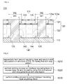
- FIG. 1 is a view showing a circuit board in accordance with an embodiment of the present invention.
- a circuit board 100 in accordance with an embodiment of the present invention may include a base substrate 110 , an interlayer insulating layer 120 , an etch stop pattern 130 , and a via structure 140 .
- the base substrate 110 may be a plate for manufacture of the components 120 , 130 , and 140 of the circuit board 100 .
- the base substrate 110 may be a core substrate formed by processing a copper clad laminate (CCL).
- the base substrate 110 may be an insulation film called a green sheet.
- the interlayer insulating layer 120 may have multilayered insulating layers.
- the interlayer insulating layer 120 may have a first insulating layer 122 and a second insulating layer 124 which are sequentially laminated on the base substrate 110 .
- the first insulating layer 122 may be a photosensitive insulating layer.
- the first insulating layer 122 may be a photoresist layer.
- the second insulating layer 124 may be an insulating layer different from the first insulating layer 122 .
- the second insulating layer 124 may be a photoresist layer having different photosensitive properties from the first insulating layer 122 .
- the second insulating layer 124 may be an insulating layer such as an oxide layer or a nitride layer which doesn't have photosensitivity.
- the materials of the first and second insulating layers 122 and 124 may be changed variously and may not be limited to the above examples.
- the interlayer insulating layer 120 may have a relatively larger thickness than a typical interlayer insulating layer.
- the interlayer insulating layer 120 may have a structure in which the first and second insulating layers 122 and 124 are laminated vertically and thus may have a thickness of greater than about 2 ⁇ m, further greater than 10 ⁇ m.
- the interlayer insulating layer 120 having this structure may be provided to satisfy a circuit board requiring a via structure having a vertical height of greater than 2 ⁇ m, further greater than 10 ⁇ m.
- First and second via holes 126 and 128 may be formed in the first and second insulating layers 122 and 124 to define a space in which the via structure 140 is to be formed.
- the first via hole 126 may be a hole passing through both of the base substrate 110 and the interlayer insulating layer 120
- the second via hole 128 may be a hole passing through only the interlayer insulating layer 120 .
- the first and second via holes 126 and 128 may vertically pass through the first and second insulating layers 122 and 124 to have a generally perpendicular side surface.
- each of the first and second via holes 126 and 128 may have a structure in which an upper width (hereinafter, referred to as ‘second opening width’ W2) defined by the second insulating layer 124 is larger than a lower width (hereinafter, referred to as ‘first opening width’ W1) defined by the first insulating layer 122 .
- the etch stop pattern 130 may be disposed inside the interlayer insulating layer 120 to cross the interlayer insulating layer 120 in the horizontal direction.
- the etch stop pattern 130 may be disposed between the first insulating layer 122 and the second insulating layer 124 .
- An opening for defining the first opening width W1 may be formed in the etch stop pattern 130 in the process of forming the first and second via holes 126 and 128 .
- the etch stop pattern 130 may be formed of a material having a different etch selectivity from the interlayer insulating layer 120 .
- the etch stop pattern 130 may be formed of an insulating material having a remarkably lower etch rate than the interlayer insulating layer 120 .
- the via structure 140 may have a through via 142 and a buried via 144 .
- the through via 142 may have a structure passing through both of the base substrate 110 and the interlayer insulating layer 120
- the buried via 144 may have a structure passing through only the interlayer insulating layer 120 .
- the through via 142 may be filled in the first via hole 126
- the buried via 144 may be filled in the second via hole 128 .
- the via structure 140 may be formed by filling a plating layer in the first and second via holes 126 and 128 through a single plating process. Since the first and second via holes 126 and 128 have a vertically perpendicular side surface, the through via 142 and the buried via 144 also can have a vertically perpendicular side surface structure. Further, as described above, since the second opening width W2 is larger than the first opening width W1, an upper portion of the via structure 140 , which is surrounded by the second insulating layer 124 , may have a larger width than a lower portion of the via structure 140 , which is surrounded by the first insulating layer 122 .
- the lower portion of the via structure 140 may be used as a via body, and the upper portion thereof may be used as a via pad.
- the via pad and the via body may be integrally formed of the same material.
- the circuit board in accordance with an embodiment of the present invention may include the base substrate 110 , the interlayer insulating layer 120 formed on the base substrate 110 and having a multilayer structure and a relatively large thickness, and the via structure 140 passing through at least the interlayer insulating layer 120 of the base substrate 110 and the interlayer insulating layer 120 , wherein the via structure 140 may have a vertically perpendicular side surface.
- the circuit board in accordance with the present invention has a structure in which a via structure, which vertically passes through a base substrate and an interlayer insulating layer having a large thickness, has a vertically perpendicular side surface, it is possible to have a fine-pitch via structure by reducing the interval between the via structures.
- the thickness of the interlayer insulating layer is greater than 2 ⁇ m, further greater than 10 ⁇ m, it is possible to reduce the interval between the vertically perpendicular via structures to less than 30 ⁇ m.
- the circuit board 100 in accordance with an embodiment of the present invention may include the base substrate 110 , the interlayer insulating layer 120 laminated on the base substrate 110 , and the via structure 140 passing through at least the interlayer insulating layer 120 of the base substrate 110 and the interlayer insulating layer 120 .
- the upper portion of the via structure 140 has a larger width than the lower portion thereof, the upper portion of the via structure 140 may be used as a via pad for electrical connection with a circuit pattern or a connection terminal of another layer of the via structure 140 .
- the via structure 140 may have a structure in which the via body for interlayer conduction and the via pad for connecting the via body to the other side circuit are integrally formed.
- the circuit board in accordance with the present invention can integrally form a via body and a via pad for connecting the via body to the other side circuit in a via structure for interlayer conduction, it is possible to improve bonding reliability of the via and efficiency of manufacturing processes of the via compared to a via structure of which a via body and a via pad (or via land) are manufactured by separate processes.
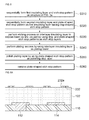
- FIG. 2 is a flowchart showing a method for manufacturing a circuit board in accordance with an embodiment of the present invention
- FIGS. 3 a to 3 e are views for explaining a process of manufacturing a circuit board in accordance with an embodiment of the present invention.
- a base substrate 100 having a base via 112 and a connection pad 114 is prepared (S 110 ).
- the step of preparing the base substrate 110 may be performed by forming a via hole in a copper clad laminate, forming a plating layer on the copper clad laminate, and patterning the plating layer.
- the step of preparing the base substrate 110 may be performed by forming a via hole in a predetermined insulation sheet and performing a plating process.
- the base via 112 may be a column-shaped interlayer conducting via which passes through the base substrate 110
- the connection pad 114 may be a plate-shaped metal pad which covers one surface of the base substrate 110 .
- a first insulating layer 122 is formed on the base substrate 110 (S 120 ).
- the step of forming the first insulating layer 122 may be performed by forming a coating layer on the base substrate 110 with a photosensitive insulating material and curing the coating layer.
- the formation of the first insulating layer 122 may be performed by forming an insulating layer such as an oxide layer or a nitride layer, not a photosensitive insulating layer.
- An etch stop pattern 130 is formed on the first insulating layer 122 to expose portions of the first insulating layer 122 which are opposite to the base via 112 and the connection pad 114 (S 130 ).
- the formation of the etch stop pattern 130 may be performed by forming an insulating pattern, which may have a different etch selectivity from the first insulating layer 122 , in the subsequent etching process of the first insulating layer 120 .
- a second insulating layer 124 is formed to cover the etch stop pattern 130 (S 140 ).
- the step of forming the second insulating layer 124 may be performed by forming a photosensitive resist layer on the first insulating layer 122 having the etch stop pattern 130 thereon and curing the photosensitive resist layer.
- the second insulating layer 124 may have a lower etch rate than the first insulating layer 122 . In this case, it is possible to give an etch selectivity to a region of a second opening width W2 in the etching process described below by performing exposure and developing processes on the photosensitive resist layer.
- an interlayer insulating layer 120 which consists of the first insulating layer 122 and the second insulating layer 124 sequentially laminated on the substrate 110 , can be formed on the substrate 110 , and the etch stop pattern 130 can be provided inside the interlayer insulating layer 120 to cross the interlayer insulating layer 120 in the horizontal direction.
- an etching process is performed on the interlayer insulating layer 120 to expose the base via 112 and the connection pad 114 by using the etch stop pattern 130 as an etch stop layer (S 150 ).
- the etching process may use a method that can pass through the thick interlayer insulating layer 120 having a multilayer structure consisting of the first and second insulating layers 122 and 124 by a single process.
- a method that can pass through the interlayer insulating layer 120 having a thickness of greater than about 2 ⁇ m, further greater than 10 ⁇ m may be preferable.
- the etching process may be a reactive ion etching (RIE) process.
- the RIE process may be an anisotropic etching process or an isotropic etching process.
- the RIE process may etch the interlayer insulating layer 120 using ions having a directivity vertically perpendicular to the base substrate 110 . Accordingly, a first through hole 126 , which exposes the base via 112 , and a second through hole 128 , which exposes the connection pad 114 , can be formed in the interlayer insulating layer 120 .
- first and second through holes 126 and 128 may have a vertically perpendicular side wall through the above RIE process. Further, etching conditions of the etching process may be adjusted so that an opening width (hereinafter, referred to as ‘second opening width’ W2) of the first and second through holes 126 and 128 in the second insulating layer 124 is larger than an opening width (hereinafter, referred to as ‘first opening width’ W1) of the first and second through holes 126 and 128 in the first insulating layer 122 .
- second opening width’ W2 an opening width of the first and second through holes 126 and 128 in the second insulating layer 124 is larger than an opening width (hereinafter, referred to as ‘first opening width’ W1) of the first and second through holes 126 and 128 in the first insulating layer 122 .
- RIE ions collide with a somewhat larger region than the first opening width W1 by the RIE process so that the RIE ions etch the second insulating layer 124 with the second opening width W2 up to the etch stop pattern 130 and etch the first insulating layer 122 with the first opening width W1 from the etch stop pattern 130 . That is, it is possible to form the first and second through holes 126 and 128 having the stepped side surfaces by using the second insulating layer 124 and the etch stop pattern 130 having different etch selectivity.
- a plating process is performed by using the interlayer insulating layer 120 as a plating resist (S 160 ).
- the plating process may be an electroless plating process.
- the plating process may be an electroplating process using a seed layer as a seed after forming the metal seed layer on a surface of the interlayer insulating layer 120 exposed by the first and second through holes 126 and 128 .
- the plating layer may be polished by using the interlayer insulating layer 120 as a polishing stop layer. Accordingly, a via structure 140 having a through via 142 and a buried via 144 which vertically pass the interlayer insulating layer 120 and of which upper surfaces are coplanar with an upper surface of the interlayer insulating layer 120 can be formed on the base substrate 110 .
- a width of an upper portion of the via structure 140 formed within the second opening width W2 may be larger than a width of a lower portion of the via structure 140 formed within the first opening width W1.
- the upper portion of the via structure 140 formed within the second opening width W2 may be used as a via pad of the through via 142 and the buried via 144 .
- the method for manufacturing a circuit board in accordance with an embodiment of the present invention may form the via structure 140 , which fills the first and second through holes 126 and 128 , by forming the first insulating layer 122 and the second insulating layer 124 on the base substrate 110 with the etch stop pattern 130 interposed therebetween, performing an etching process on the second insulating layer 124 and the first insulating layer 122 by using the etch stop pattern 130 as an etch stop layer, and performing a plating process.
- the via structure 140 having a vertically perpendicular side wall while passing through the interlayer insulating layer 120 having a relatively large thickness by using the RIE process having high anisotropic properties as the etching process.
- the method for manufacturing a circuit board in accordance with an embodiment of the present invention forms a multilayered interlayer insulating layer having an etch stop pattern embedded therein and forms a via structure which passes through the interlayer insulating layer by performing an RIE process using the etch stop pattern as an etch stop layer on the interlayer insulating layer, it is possible to form a via structure having a vertically perpendicular side surface on the relatively thick interlayer insulating layer, thus forming a fine-pitch via structure.
- the method for manufacturing a circuit board in accordance with an embodiment of the present invention can form a via structure having a vertically perpendicular side surface even when the thickness of the interlayer insulating layer is greater than 2 ⁇ m, compared to a conventional method that forms a via structure having an inclined side surface when the thickness of an interlayer insulating layer is greater than 2 ⁇ m.
- the method for manufacturing a circuit board in accordance with an embodiment of the present invention may form the via structure 140 by forming the first and second through holes 126 and 128 , whose upper width (that is, the second opening width: W2) is larger than the lower width (that is, the first opening width: W1), in the interlayer insulating layer 120 and forming the plating layer on the first and second through holes 126 and 128 .
- the method for manufacturing a circuit board in accordance with an embodiment of the present invention can form a via and a via pad at the same time by performing a plating process to form a via structure after forming a via hole having a larger upper width than a lower width in an interlayer insulating layer and using a plated portion formed within the upper width as the via pad of the via structure.
- a plating process to form a via structure after forming a via hole having a larger upper width than a lower width in an interlayer insulating layer and using a plated portion formed within the upper width as the via pad of the via structure.
- FIG. 4 is a view showing a modified example of the circuit board in accordance with an embodiment of the present invention.
- a circuit board 101 in accordance with a modified example of the present invention may include a base substrate 110 , an interlayer insulating layer 120 which covers the base substrate 110 , an etch stop pattern 131 provided on the interlayer insulating layer 120 , and a via structure 140 which vertically passes through at least the interlayer insulating layer 120 of the base substrate 110 and the interlayer insulating layer 120 .
- the interlayer insulating layer 120 may have a multilayer structure consisting of a first insulating layer 122 and a second insulating layer 124 sequentially laminated on the base substrate 110 .
- the first and second insulating layers 122 and 124 may be made of the same material.
- the first and second insulating layers 122 and 124 may be made of photosensitive insulating materials having the same photosensitive properties.
- the first and second insulating layers 122 and 124 may be made of an insulating material such as an oxide layer or a nitride layer, not a photosensitive layer.
- the via structure 140 may have a through via 142 , which passes through the base substrate 110 as well as the first and second insulating layers 122 and 124 , and a buried via 144 , which passes through the first and second insulating layers 122 and 124 .
- the through via 142 may be formed inside a first via hole 126 , which passes through the base substrate 110 and the interlayer insulating layer 120
- the buried via 144 may be formed inside a second via hole 128 , which passes through the interlayer insulating layer 120 .
- the etch stop pattern 131 may include a first etch stop pattern 133 and a second etch stop pattern 135 .
- the first etch stop pattern 133 may be generally equal to the etch stop pattern 130 described above with reference to FIG. 1 .
- the second etch stop pattern 135 may be disposed on the second insulating layer 124 , unlike the first etch stop pattern 133 disposed inside the interlayer insulating layer 120 .
- the second etch stop pattern 135 may be provided to surround an upper end side surface of the via structure 140 .
- the second etch stop pattern 135 may be made of the same material as the first etch stop pattern 133 .
- the first etch stop pattern 131 may be provided to define a lower width of the via structure 140
- the second etch stop pattern 133 may be provided to define an upper width of the via structure 140
- the first etch stop pattern 131 may have a first opening 133 a for defining the lower width of the via structure 140 surrounded by the first insulating layer 122
- the second etch stop pattern 133 may have a second opening 135 a for defining the upper width of the via structure 140 surrounded by the second insulating layer 122
- the first and second openings 133 a and 135 a may be vertically opposite to each other, and the second opening 135 a may have a larger width than the first opening 133 a .
- the first and second etch stop patterns 131 and 133 may give an etch selectivity to each layer of the interlayer insulating layer 120 consisting of the first and second insulating layers 122 and 124 made of the same material in the etching process for forming the first and second via holes 126 and 128 to manufacture the via structure 140 having different widths based on the first and second etch stop patterns 131 and 135 .
- FIG. 5 is a flowchart showing a method for manufacturing the circuit board shown in FIG. 4
- FIGS. 6 a to 6 c are views for explaining a process of manufacturing the circuit board shown in FIG. 4 .
- a second insulating layer 124 and a second etching stop pattern 135 are sequentially formed on the structure having a first etch stop pattern 133 shown in FIG. 3 b (S 210 ). More specifically, the second insulating layer 124 and the second etch stop pattern 135 may be sequentially formed on the resultant obtained by forming the first etch stop pattern 133 on a base substrate 110 covered with a first insulating layer 122 .
- the first etch stop pattern 133 may have a first opening 133 a which exposes the first insulating layer 122 opposite to a base via 112 and a connection pad 114
- the second etch stop pattern 135 may have a second opening 135 a which is opposite to the first opening 133 a and has a larger width than the first opening 133 a
- an etch stop pattern 131 having the first etch stop pattern 133 formed inside an interlayer insulating layer 120 and the second etch stop pattern 135 formed on the interlayer insulating layer 120 may be formed on the base substrate 110 .
- an etching process using the etch stop pattern 131 as an etch stop layer is formed on the interlayer insulating layer 120 to expose the base via 112 and the connection pad 114 (S 220 ).
- the etching process may be an RIE process. Accordingly, a first via hole 126 , which exposes the base via 112 , and a second via hole 128 , which exposes the connection pad 114 , may be formed in the interlayer insulating layer 120 . At this time, the first and second via holes 126 and 128 may have a stepped side surface based on a boundary between the first and second insulating layers 122 and 124 .
- a plating process is formed by using the interlayer insulating layer 120 as a plating resist (S 230 ). Accordingly, a via structure 140 having a through hole 142 and a buried via 144 , which vertically pass through the interlayer insulating layer 120 , may be formed on the base substrate 110 . At this time, upper ends of the through via 142 and the buried via 144 may be surrounded by the second etch stop pattern 135 of the etch stop pattern 131 .
- the step of removing the second etch stop pattern 135 may be additionally performed to project the via structure upwardly from an upper surface of the interlayer insulating layer 120 as much as the thickness of the second etch stop pattern 135 .
- the second etch stop pattern 135 may be removed from the interlayer insulating layer 120 to manufacture a circuit board only having the first etch stop pattern 133 .
- circuit board in accordance with another embodiment of the present invention will be described in detail.
- descriptions overlapping with those of the circuit boards 100 and 101 and the methods for manufacturing the same described above will be omitted or simplified.
- FIG. 7 is a view showing a circuit board in accordance with another embodiment of the present invention.
- a circuit board 200 in accordance with another embodiment of the present invention may include a base substrate 110 , a multilayered interlayer insulating layer 120 which covers the base substrate 110 , a via structure 140 vertically passing through at least the interlayer insulating layer 120 of the base substrate 110 and the interlayer insulating layer 120 , and a ring-shaped etch stop pattern 232 provided on the interlayer insulating layer 120 .
- the via structure 140 may have a through via 142 and a buried via 144 .
- the ring-shaped etch stop pattern 232 may be disposed between a first insulating layer 122 and a second insulating layer 124 of the interlayer insulating layer 120 in the horizontal direction.
- An opening for defining a first opening width W1 may be formed in the ring-shaped etch stop pattern 232 in a process of forming first and second via holes 126 and 128 .
- the etch stop pattern 232 may be formed of a material having a different etch selectivity from the interlayer insulating layer 120 .
- the etch stop pattern 232 may be a conductive layer having a remarkably lower etch rate than the interlayer insulating layer 120 and may be formed of various types of metal materials.
- the ring-shaped etch stop pattern 232 may be provided in the shape of a ring surrounding the via structure 140 to prevent electrical connection between the through via 142 and the buried via 144 . More specifically, the etch stop pattern 232 may surround a portion of the through via 142 adjacent to a boundary between the first and second insulating layers 122 and 124 with a predetermined width and may surround a portion of the buried via 144 adjacent to the boundary with a predetermined width.
- the circuit board 200 in accordance with another embodiment of the present invention may include the base substrate 110 , the interlayer insulating layer 120 , the via structure 140 , and the ring-shaped etch stop pattern 232 made of a metal material, wherein the ring-shaped etch stop pattern 232 may have a structure surrounding the individual vias 142 and 144 only with a predetermined with to prevent the electrical connection between the individual vias 142 and 144 .
- the etch stop pattern 232 may be provided to surround each of the individual vias 142 and 144 in a ring shape.
- the circuit board in accordance with the present invention can form a via hole using an etch stop pattern with the remarkably improved etch selectivity to the interlayer insulating layer by forming the etch stop pattern, which is used to form a via structure, with a metal material.
- FIG. 8 is a flowchart showing a method for manufacturing a circuit board in accordance with another embodiment of the present invention
- FIGS. 9 a to 9 d are views for explaining a process of manufacturing a circuit board in accordance with another embodiment of the present invention.
- a first insulating layer 122 and a ring-shaped etch stop pattern 232 are formed on the structure of FIG. 3 a (S 310 ). Accordingly, the first insulating layer 122 and the ring-shaped etch stop pattern 232 can be formed on a base substrate 210 having a base via 112 and a connection pad 114 . At this time, a third opening 232 a may be formed in regions of the ring-shaped etch stop pattern 232 opposite to the base via 112 and the connection pad 114 .
- a second insulating layer 124 and a plate-shaped etch stop pattern 234 are formed on the first insulating layer 122 having the etch stop pattern 232 thereon (S 320 ).
- a fourth opening 234 a which is opposite to the third opening 232 a and has a larger width than the third opening 232 a , may be formed in the plate-shaped etch stop pattern 234 .
- the plate-shaped etch stop pattern 234 may be provided in the shape of a porous plate having the fourth openings 234 a so that a plurality of individual vias can be connected in one plate shape when the plate-shaped etch stop pattern 234 is seen from above.
- an etching process is performed on the interlayer insulating layer 120 to expose the base via 112 and the connection pad 114 by using the etch stop pattern 230 as an etch stop layer (S 330 ).
- the etching process may be an RIE process. Accordingly, a first through hole 126 , which exposes the base via 112 , and a second through hole 128 , which exposes the connection pad 114 , can be formed in the interlayer insulating layer 120 .
- a plating process is performed by using the interlayer insulating layer 120 as a plating resist (S 340 ). Accordingly, a via structure 140 having a through via 142 and a buried via 144 can be formed by filling a plating layer in the first and second through holes 126 and 128 .
- the plating layer is polished by using the plated-shaped etch stop pattern 234 as a polishing stop layer (S 350 ). Accordingly, the via structure 140 having the through hole 142 and the buried via 144 that vertically pass through the interlayer insulating layer 120 can be formed on the base substrate 110 .
- the plate-shaped etch stop pattern 234 is removed (S 360 ).
- the plated-shaped etch stop pattern 234 of the etch stop pattern 230 is made of a material equal or similar to that of the ring-shaped etch stop pattern 232 , an electrical short may occur in the additionally formed circuit structure due to the plate-shaped etch stop pattern 234 . Accordingly, it is possible to prevent this electrical short by removing the plate-shaped etch stop pattern 234 .
- the method for manufacturing a circuit board in accordance with an embodiment of the present invention can form a via hole using an etch stop pattern having the remarkably improved etch selectivity to an interlayer insulating layer by forming the etch stop pattern, which is used to form a via structure, with a metal material, thereby improving efficiency of the process of forming the via hole.
- the circuit board in accordance with the present invention has a structure in which a via structure vertically passing through an interlayer insulating layer having a relatively large thickness has a vertically perpendicular side surface, it is possible to implement a fine pitch of the via structure by reducing the interval between the via structures.
- the circuit board in accordance with the present invention can form an etch stop pattern, which is used to form a via structure, with a metal material, it is possible to form a via hole by using the etch stop pattern with the remarkably improved etch selectivity to an interlayer insulating layer.
- the method for manufacturing a printed circuit in accordance with an embodiment of the present invention forms a multilayered interlayer insulating layer having an etch stop pattern embedded therein and forms a via structure which passes through the interlayer insulating layer by performing an RIE process using the etch stop pattern as an etch stop layer on the interlayer insulating layer, it is possible to form a via structure having a vertically perpendicular side surface in the relatively thick interlayer insulating layer, thus forming a fine-pitch via structure.
- the method for manufacturing a circuit board in accordance with an embodiment of the present invention can form a via structure having a vertically perpendicular side surface even when the thickness of the interlayer insulating layer is greater than 2 ⁇ m, compared to a conventional method that forms a via structure having an inclined side surface when the thickness of an interlayer insulating layer is greater than 2 ⁇ m.
- the method for manufacturing a printed circuit in accordance with an embodiment of the present invention can form a via and a via pad at the same time by performing a plating process to form a via structure after forming a via hole having a larger upper width than a lower width in an interlayer insulating layer and using a plated portion formed within the upper width as the via pad of the via structure.
- a plating process to form a via structure after forming a via hole having a larger upper width than a lower width in an interlayer insulating layer and using a plated portion formed within the upper width as the via pad of the via structure.
- the circuit board in accordance with the present invention can form a via hole using an etch stop pattern having the remarkably improved etch selectivity to an interlayer insulating layer by forming the etch stop pattern, which is used to form a via structure, with a metal material, thereby improving efficiency of the process of forming the via hole.
Landscapes
- Engineering & Computer Science (AREA)
- Microelectronics & Electronic Packaging (AREA)
- Manufacturing & Machinery (AREA)
- Computer Hardware Design (AREA)
- Power Engineering (AREA)
- Chemical & Material Sciences (AREA)
- Chemical Kinetics & Catalysis (AREA)
- General Chemical & Material Sciences (AREA)
- Production Of Multi-Layered Print Wiring Board (AREA)
- Printing Elements For Providing Electric Connections Between Printed Circuits (AREA)
- Drying Of Semiconductors (AREA)
- Internal Circuitry In Semiconductor Integrated Circuit Devices (AREA)
Applications Claiming Priority (2)
| Application Number | Priority Date | Filing Date | Title |
|---|---|---|---|
| KR1020120157167A KR101872532B1 (ko) | 2012-12-28 | 2012-12-28 | 회로 기판 및 그 제조 방법 |
| KR10-2012-0157167 | 2012-12-28 |
Publications (2)
| Publication Number | Publication Date |
|---|---|
| US20140182915A1 US20140182915A1 (en) | 2014-07-03 |
| US9173291B2 true US9173291B2 (en) | 2015-10-27 |
Family
ID=51015864
Family Applications (1)
| Application Number | Title | Priority Date | Filing Date |
|---|---|---|---|
| US14/060,345 Active 2033-10-26 US9173291B2 (en) | 2012-12-28 | 2013-10-22 | Circuit board and method for manufacturing the same |
Country Status (3)
| Country | Link |
|---|---|
| US (1) | US9173291B2 (ko) |
| JP (1) | JP2014131011A (ko) |
| KR (1) | KR101872532B1 (ko) |
Cited By (2)
| Publication number | Priority date | Publication date | Assignee | Title |
|---|---|---|---|---|
| US20170196096A1 (en) * | 2016-01-05 | 2017-07-06 | Ibiden Co., Ltd. | Printed wiring board and method for manufacturing printed wiring board |
| US10535534B2 (en) * | 2016-05-12 | 2020-01-14 | Samsung Electronics Co., Ltd. | Method of fabricating an interposer |
Families Citing this family (6)
| Publication number | Priority date | Publication date | Assignee | Title |
|---|---|---|---|---|
| KR102211741B1 (ko) * | 2014-07-21 | 2021-02-03 | 삼성전기주식회사 | 인쇄회로기판 및 인쇄회로기판의 제조 방법 |
| CN104582330B (zh) * | 2014-12-31 | 2018-07-20 | 广州兴森快捷电路科技有限公司 | 埋盲孔结构的ate板的制作方法 |
| US10251270B2 (en) * | 2016-09-15 | 2019-04-02 | Innovium, Inc. | Dual-drill printed circuit board via |
| CN109803481B (zh) * | 2017-11-17 | 2021-07-06 | 英业达科技有限公司 | 多层印刷电路板及制作多层印刷电路板的方法 |
| KR102624491B1 (ko) * | 2018-11-06 | 2024-01-15 | 삼성디스플레이 주식회사 | 표시 장치 |
| KR102375686B1 (ko) | 2020-08-12 | 2022-03-16 | 경북대학교 산학협력단 | 금연구역 관리 서비스 방법 및 시스템 |
Citations (4)
| Publication number | Priority date | Publication date | Assignee | Title |
|---|---|---|---|---|
| JP2001313336A (ja) | 2000-04-21 | 2001-11-09 | Ind Technol Res Inst | 銅構造の製造方法 |
| US20030213980A1 (en) * | 2002-04-12 | 2003-11-20 | Jun Tanaka | Semiconductor device |
| JP2005268312A (ja) | 2004-03-16 | 2005-09-29 | Semiconductor Leading Edge Technologies Inc | レジスト除去方法及びそれを用いて製造した半導体装置 |
| US20130020719A1 (en) * | 2011-07-18 | 2013-01-24 | Samsung Electronics Co., Ltd. | Microelectronic devices including through silicon via structures having porous layers |
Family Cites Families (8)
| Publication number | Priority date | Publication date | Assignee | Title |
|---|---|---|---|---|
| JP2881963B2 (ja) * | 1990-05-25 | 1999-04-12 | ソニー株式会社 | 配線基板及びその製造方法 |
| JP2001274243A (ja) * | 2000-03-24 | 2001-10-05 | Sanyo Electric Co Ltd | 半導体装置の製造方法 |
| JP2001358464A (ja) * | 2000-06-15 | 2001-12-26 | Nippon Avionics Co Ltd | ビルドアッププリント配線板およびその製造方法 |
| JP2002111213A (ja) * | 2000-09-26 | 2002-04-12 | Nippon Mektron Ltd | 任意層間接続用バイア・ホールを有する多層プリント基板およびその製造方法 |
| JP2004031918A (ja) * | 2002-04-12 | 2004-01-29 | Hitachi Ltd | 半導体装置 |
| JP2006253189A (ja) * | 2005-03-08 | 2006-09-21 | Fujitsu Ltd | 多層回路基板及びその製造方法 |
| US20070281464A1 (en) * | 2006-06-01 | 2007-12-06 | Shih-Ping Hsu | Multi-layer circuit board with fine pitches and fabricating method thereof |
| JP4749966B2 (ja) * | 2006-07-25 | 2011-08-17 | 三菱電機株式会社 | プリント配線板の製造方法 |
-
2012
- 2012-12-28 KR KR1020120157167A patent/KR101872532B1/ko active IP Right Grant
-
2013
- 2013-10-22 US US14/060,345 patent/US9173291B2/en active Active
- 2013-10-31 JP JP2013226577A patent/JP2014131011A/ja active Pending
Patent Citations (4)
| Publication number | Priority date | Publication date | Assignee | Title |
|---|---|---|---|---|
| JP2001313336A (ja) | 2000-04-21 | 2001-11-09 | Ind Technol Res Inst | 銅構造の製造方法 |
| US20030213980A1 (en) * | 2002-04-12 | 2003-11-20 | Jun Tanaka | Semiconductor device |
| JP2005268312A (ja) | 2004-03-16 | 2005-09-29 | Semiconductor Leading Edge Technologies Inc | レジスト除去方法及びそれを用いて製造した半導体装置 |
| US20130020719A1 (en) * | 2011-07-18 | 2013-01-24 | Samsung Electronics Co., Ltd. | Microelectronic devices including through silicon via structures having porous layers |
Cited By (3)
| Publication number | Priority date | Publication date | Assignee | Title |
|---|---|---|---|---|
| US20170196096A1 (en) * | 2016-01-05 | 2017-07-06 | Ibiden Co., Ltd. | Printed wiring board and method for manufacturing printed wiring board |
| US10535534B2 (en) * | 2016-05-12 | 2020-01-14 | Samsung Electronics Co., Ltd. | Method of fabricating an interposer |
| US11018026B2 (en) | 2016-05-12 | 2021-05-25 | Samsung Electronics Co., Ltd. | Interposer, semiconductor package, and method of fabricating interposer |
Also Published As
| Publication number | Publication date |
|---|---|
| US20140182915A1 (en) | 2014-07-03 |
| JP2014131011A (ja) | 2014-07-10 |
| KR101872532B1 (ko) | 2018-06-28 |
| KR20140086535A (ko) | 2014-07-08 |
Similar Documents
| Publication | Publication Date | Title |
|---|---|---|
| US9173291B2 (en) | Circuit board and method for manufacturing the same | |
| US8227710B2 (en) | Wiring structure of printed wiring board and method for manufacturing the same | |
| JP4331769B2 (ja) | 配線構造及びその形成方法並びにプリント配線板 | |
| JP4800253B2 (ja) | 配線基板の製造方法 | |
| JP5101451B2 (ja) | 配線基板及びその製造方法 | |
| US9899235B2 (en) | Fabrication method of packaging substrate | |
| US7698813B2 (en) | Method for fabricating conductive blind via of circuit substrate | |
| JP2008282842A (ja) | 配線基板及びその製造方法 | |
| JP2019106523A (ja) | インダクター及びその製造方法 | |
| JP4890959B2 (ja) | 配線基板及びその製造方法並びに半導体パッケージ | |
| US9338887B2 (en) | Core substrate, manufacturing method thereof, and structure for metal via | |
| US20150101857A1 (en) | Printed circuit board and method for manufacturing the same | |
| JP2014504019A (ja) | 絶縁された金属基板を有するプリント回路板 | |
| TWI387423B (zh) | 印刷電路板及其製造方法 | |
| KR101039774B1 (ko) | 인쇄회로기판 제조를 위한 범프 형성 방법 | |
| JP4227967B2 (ja) | 基板及び電子部品の製造方法 | |
| KR101558579B1 (ko) | 인쇄회로기판 및 그 제조방법 | |
| KR100652132B1 (ko) | 인쇄 회로 기판 및 이의 제작 방법 | |
| JP5468572B2 (ja) | 配線基板 | |
| JP2022138469A (ja) | 多層配線基板及びその製造方法 | |
| JP2019179803A (ja) | 印刷配線板及び印刷配線板の製造方法 | |
| JP2005183687A (ja) | 半導体装置及びその製造方法 | |
| KR20190087032A (ko) | 기판의 휨을 개선할 수 있는 인쇄회로기판의 제조 방법 및 이에 의해 제조되는 인쇄회로기판 | |
| JP2009081404A (ja) | 多層配線板の製造方法 |
Legal Events
| Date | Code | Title | Description |
|---|---|---|---|
| AS | Assignment |
Owner name: SAMSUNG ELECTRO-MECHANICS CO., LTD., KOREA, REPUBL Free format text: ASSIGNMENT OF ASSIGNORS INTEREST;ASSIGNORS:HAN, SUNG;KWEON, YOUNG DO;KIM, JIN GU;AND OTHERS;REEL/FRAME:031589/0957 Effective date: 20130405 |
|
| STCF | Information on status: patent grant |
Free format text: PATENTED CASE |
|
| FEPP | Fee payment procedure |
Free format text: PAYOR NUMBER ASSIGNED (ORIGINAL EVENT CODE: ASPN); ENTITY STATUS OF PATENT OWNER: LARGE ENTITY |
|
| MAFP | Maintenance fee payment |
Free format text: PAYMENT OF MAINTENANCE FEE, 4TH YEAR, LARGE ENTITY (ORIGINAL EVENT CODE: M1551); ENTITY STATUS OF PATENT OWNER: LARGE ENTITY Year of fee payment: 4 |
|
| MAFP | Maintenance fee payment |
Free format text: PAYMENT OF MAINTENANCE FEE, 8TH YEAR, LARGE ENTITY (ORIGINAL EVENT CODE: M1552); ENTITY STATUS OF PATENT OWNER: LARGE ENTITY Year of fee payment: 8 |