US8334971B2 - Apparatus for imaging the inner surface of a cavity within a workpiece - Google Patents
Apparatus for imaging the inner surface of a cavity within a workpiece Download PDFInfo
- Publication number
- US8334971B2 US8334971B2 US12/662,813 US66281310A US8334971B2 US 8334971 B2 US8334971 B2 US 8334971B2 US 66281310 A US66281310 A US 66281310A US 8334971 B2 US8334971 B2 US 8334971B2
- Authority
- US
- United States
- Prior art keywords
- optical system
- illumination
- light source
- imaging
- axial
- Prior art date
- Legal status (The legal status is an assumption and is not a legal conclusion. Google has not performed a legal analysis and makes no representation as to the accuracy of the status listed.)
- Active, expires
Links
Images


Classifications
-
- G—PHYSICS
- G02—OPTICS
- G02B—OPTICAL ELEMENTS, SYSTEMS OR APPARATUS
- G02B23/00—Telescopes, e.g. binoculars; Periscopes; Instruments for viewing the inside of hollow bodies; Viewfinders; Optical aiming or sighting devices
- G02B23/24—Instruments or systems for viewing the inside of hollow bodies, e.g. fibrescopes
- G02B23/2407—Optical details
- G02B23/2461—Illumination
-
- G—PHYSICS
- G01—MEASURING; TESTING
- G01N—INVESTIGATING OR ANALYSING MATERIALS BY DETERMINING THEIR CHEMICAL OR PHYSICAL PROPERTIES
- G01N21/00—Investigating or analysing materials by the use of optical means, i.e. using sub-millimetre waves, infrared, visible or ultraviolet light
- G01N21/84—Systems specially adapted for particular applications
- G01N21/88—Investigating the presence of flaws or contamination
- G01N21/95—Investigating the presence of flaws or contamination characterised by the material or shape of the object to be examined
- G01N21/954—Inspecting the inner surface of hollow bodies, e.g. bores
-
- G—PHYSICS
- G02—OPTICS
- G02B—OPTICAL ELEMENTS, SYSTEMS OR APPARATUS
- G02B13/00—Optical objectives specially designed for the purposes specified below
- G02B13/06—Panoramic objectives; So-called "sky lenses" including panoramic objectives having reflecting surfaces
-
- G—PHYSICS
- G02—OPTICS
- G02B—OPTICAL ELEMENTS, SYSTEMS OR APPARATUS
- G02B23/00—Telescopes, e.g. binoculars; Periscopes; Instruments for viewing the inside of hollow bodies; Viewfinders; Optical aiming or sighting devices
- G02B23/24—Instruments or systems for viewing the inside of hollow bodies, e.g. fibrescopes
- G02B23/2407—Optical details
- G02B23/2423—Optical details of the distal end
- G02B23/243—Objectives for endoscopes
-
- G—PHYSICS
- G01—MEASURING; TESTING
- G01N—INVESTIGATING OR ANALYSING MATERIALS BY DETERMINING THEIR CHEMICAL OR PHYSICAL PROPERTIES
- G01N21/00—Investigating or analysing materials by the use of optical means, i.e. using sub-millimetre waves, infrared, visible or ultraviolet light
- G01N21/84—Systems specially adapted for particular applications
- G01N21/88—Investigating the presence of flaws or contamination
- G01N21/8806—Specially adapted optical and illumination features
- G01N2021/8822—Dark field detection
- G01N2021/8825—Separate detection of dark field and bright field
Definitions
- the invention relates to an apparatus of the type for imaging the inner surface of a cavity in a workpiece.
- An apparatus of the relevant type for the imaging of the inner surface of a cavity in a workpiece is known from WO 2009/003692, the apparatus including an optical system comprising a panoramic field of view that is linked to an imager and downstream evaluation device by an image communication link.
- the known device furthermore includes an illumination system to illuminate an imaging region of the inner surface, which region is captured by the optical system.
- Systems of this type are employed, for example, during the inspection of cylinder bores in crankcases, and function to image the radial inner surface of the cylinder bore and then to examine whether the bore meets specified requirements in terms of surface quality.
- An object of the invention is to overcome the drawbacks of the prior art.
- An object of the invention is to provide an apparatus for imaging the inner surface of a cavity in a workpiece, the capabilities of which, in terms of imaging the inner surface, have been expanded.
- the invention including an apparatus for imaging the inner surface of a cavity in a workpiece, which apparatus includes an optical system having a panoramic field of view that is linked to an imager and a downstream evaluation device with an image communication link; and there is an illumination system having a light source to illuminate an imaging region of the inner surface captured by the optical system.
- the illumination system is disposed in such a way relative to the optical system, and for which a beam path of the light source is selected in such a way, that a first axial section of the imaging region is able to be illuminated under brightfield or bright field illumination, while simultaneously a second axial region spaced apart from the first axial region is able to be illuminated under darkfield or dark field illumination.
- the fundamental idea of the invention consists in configuring the illumination system in such a way that the imaging region of the inner surface captured by the optical system is illuminated partially under brightfield illumination and partially under darkfield illumination.
- brightfield illumination in which the light reflected by the inner surface to be imaged is used for imaging, an especially high contrast image is produced with which it is possible to detect, for example and in particular, scratches and porosities in the inner surface to be imaged.
- other structural defects such as, for example, casting defects in cast-iron parts, can be detected with a darkfield illumination in which the beam path of the light is routed so as to utilize primarily those rays scattered from the inner surface to be imaged for the purpose of imaging.
- the apparatus according to the invention thus enables the inner surface for imaging to be imaged both under brightfield illumination and also darkfield illumination.
- the apparatus according to the invention thus combines the advantages that exist for both illumination methods in terms of detecting defects.
- a feed device can be associated with the apparatus, by which device the apparatus is axially movable relative to the inner surface to be imaged. If, for example, an examined section of the inner surface examined under darkfield illumination is located in the feed direction obliquely in front of the optical system, while a section examined under brightfield illumination is located in the axial direction of the cavity approximately at the level of the optical system, or somewhat behind this system, a predetermined axial region of the inner surface can be imaged during the feed motion first under darkfield illumination, and then imaged during a continued feed motion of the apparatus under brightfield illumination.
- the device according to the invention is of relatively simple construction, and thus relatively inexpensive to produce.
- an illumination system comprising two or more light sources, of which one light source is provided to effect the brightfield illumination in the first axial section of the imaging region and a second light source is provided to effect the darkfield illumination in the second axial section.
- an advantageous embodiment of the invention provides a mirror arrangement or system, the reflection surfaces or reflective surfaces of which are disposed partially within the beam path of the light source such that, when the apparatus is in the imaging position, partial beams of the light emitted by the light source strike the second axial section of the imaging region and the reflective surface reflects other partial beams onto the first axial section.
- the simultaneous brightfield illumination and darkfield illumination, provided according to the invention, of different axial sections on the inner surface of the cavity are thus able to be realized by means of a single light source.
- Those partial beams of the emitted light that are reflected from the reflective surface onto the first axial section can function, for example, to effect the brightfield illumination, while those partial beams that pass through the reflective surface of the mirror arrangement onto the second axial section can function to effect the darkfield illumination.
- the mirror arrangement has an annular reflective surface. This then achieves an annular illumination of the inner surface of the workpiece.
- the reflective surface of the mirror arrangement can be on average configured as straight, with the result that the mirror is of a frustoconical shape.
- the reflective surface can also have a cross section embodied as a circular, aspheric, or parabolic cross section, or a cross section embodied in some other way.
- the reflective surface is coaxial relative to the optical axis of the optical system. In this manner an illumination that is uniform in the circumferential direction of the inner surface is achieved.
- the reflective surface is disposed at an angle at least in certain sections, as is provided by another advantageous development of the embodiment comprising the mirror arrangement.
- the optical system includes an image angle of >180°, preferably of about 185°.
- one section can be imaged that is disposed obliquely in the direction of the optical axis in front of the optical system and is illuminated under darkfield illumination, while one section of the inner surface can be imaged that is disposed in the direction of the optical axis at the level of the optical system or right behind the optical system, and is illuminated under brightfield illumination.
- an advantageous embodiment of the invention provides that the illumination system have an annular light source.
- the annular light source can be composed of an arrangement of multiple light-emitting diodes that are disposed behind a diffuser.
- the light source is disposed coaxially relative to the optical axis of the optical system.
- Another advantageous embodiment provides that the light source emit essentially coaxially relative to the optical axis of the optical system.
- the imager of the apparatus according to the invention can be of any appropriate construction.
- the imager can use an annular sensor that captures an annular region of the image circle.
- an advantageous embodiment of the invention provides an approach whereby the imager is constructed to capture the entire image circle of the optical system.
- the capture of the entire image circle by the optical system in particular provides the capability of simultaneously imaging multiple annular regions on the inner surface of the workpiece, of which regions at least one can be illuminated under brightfield illumination and at least one can be illuminated under darkfield illumination.
- an advantageous embodiment provides a storage device to store the image data according to the given axial position of the apparatus relative to the workpiece.
- different annular regions of the inner surface of the cavity are imaged in chronological succession during an axial feed motion by the apparatus and the image data thus obtained is stored, wherein a correlation is created between the given axial position of the apparatus and the given stored image data.
- the optical system In order to provide complete imaging circumferentially, it is advantageous for the optical system to include a panoramic field of view of 360°.
- Appropriate optical systems of this type are disclosed, for example, in U.S. Pat. No. 3,552,820, U.S. Pat. No. 5,473,474, U.S. Pat. No. 4,565,763 and EP 1 321 793 B1.
- the apparatus according to the invention is suitable for inspecting any inner surfaces of a cavity, in particular, rotationally-symmetrical, for example, cylindrical or essentially cylindrical cavities.
- a cavity in particular, rotationally-symmetrical, for example, cylindrical or essentially cylindrical cavities.
- provision is made whereby the inner surface to be imaged is of substantially rotationally-symmetrical shape, in particular, is formed by a cylinder bore of a crankcase.
- FIG. 1 is a schematic side view of a first exemplary embodiment of an apparatus according to the invention in the imaging position;
- FIG. 2 is an image on an imager of the apparatus of FIG. 1 ;
- FIG. 3 is digital images generated as in FIG. 1 of developed views of the inner surface to be imaged in the bright field and dark field;
- FIG. 4 is the same view as in FIG. 1 showing a second embodiment of an apparatus according to the;
- FIG. 5 is the same view as in FIG. 1 showing a third embodiment of an apparatus according to the invention.
- FIG. 6 is the same view as in FIG. 1 showing a fourth embodiment of an apparatus according to the invention.
- FIG. 7 is the same view as in FIG. 1 showing a fifth embodiment of an apparatus according to the invention.
- FIG. 8 is the same view as in FIG. 1 showing a sixth embodiment of an apparatus according to the invention.
- FIG. 9 is the same view as in FIG. 1 showing a seventh embodiment of an apparatus according to the invention.
- FIG. 10 is the same view as in FIG. 1 showing an eighth embodiment of an apparatus according to the invention.
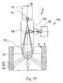
- FIG. 11 is the same view as in FIG. 1 showing a ninth embodiment of an apparatus according to the invention.
- FIG. 1 illustrates a first embodiment of an apparatus 2 according to the invention for imaging of an inner surface 4 of a cavity of a workpiece 6 .
- Inner surface 4 in the embodiment illustrated involves an inner surface of a cylinder bore of a crankcase.
- Apparatus 2 has an optical system 8 having a panoramic field of view in this embodiment of 360° that is linked to an image capturing device (imager) 10 and a following evaluation device by an image communication link, not shown.
- imager 10 is composed of a digital camera having an image sensor 12 .
- Optical system 8 in the embodiment illustrated in FIG. 1 includes a refraction-optical-imaging fisheye objective lens, the optical axis of which in FIG. 1 is identified by a dot-dash line 14
- optical system 8 has an angular field of >180°, specifically, approximately 185°, such that optical system 8 captures not only a region of inner surface 4 that is situated obliquely in front of the front lens but also a region of inner surface 4 lying further back relative to the front lens of optical system 8 .
- imager 12 is configured to capture the entire image circle of optical system 8 . Images captured by optical system 8 are recorded by image sensor 12 of imager 10 and stored in a storage device, not shown.
- Apparatus 2 includes an illumination system 16 , which according to the invention is disposed in such a way relative to optical system 8 , and for which the beam path is selected in such a way, that a first axial section of the imaging region is able to be illuminated under brightfield illumination, while simultaneously a second axial region at a distance from the first axial region is able to be illuminated under darkfield illumination.
- illumination system 16 has an annular light source 18 that in this embodiment is composed of a plurality of light-emitting diodes disposed along a circular ring, the diodes irradiating an annular diffuser.
- light source 18 is disposed in the immediate proximity of optical system 8 in the axial direction of the optical axis.
- light source 18 is oriented coaxially relative to optical axis 14 and emits essentially coaxially relative to optical axis 14 of optical system 8 .
- illumination system 16 has a mirror arrangement or mirror system 20 that in this embodiment is composed of a toroidal mirror, the reflection surface or reflective surface 20 of which is inclined relative to optical axis 14 of optical system 8 .
- reflective surface 20 has an aspheric cross-section. As is seen in FIG. 1 , reflection surface 20 is disposed partially within the beam path from light source 18 in such a way that in the imaging position of apparatus 2 shown in FIG. 1 reflective surface 20 reflects partial beams of the light emitted by light source 18 on a first axial section along inner surface 4 . A corresponding partial beam is identified in FIG. 1 by reference number 21 . Other partial beams pass by reflective surface 20 to directly strike inner surface 4 . In FIG.
- the corresponding partial beams are identified, by way of example, by reference numbers 22 , 24 , 26 .
- the first axial section of the imaging region in which partial beam 21 strikes inner surface 4 is at a certain distance in the axial direction of optical axis 14 from the second axial section in which partial beams 22 , 24 , 26 strike inner surface 4 .
- Both the first axial section and the second axial section are located within the imaging region of optical system 8 .
- the first axial section is located somewhat behind optical system 8 in the direction of the optical axis it is nevertheless captured by the imaging region due to the image angle of 185° for optical system 8 .
- a brightfield illumination is effected by the partial beams of the light emitted by light source 18 that are reflected from reflective surface 20 onto inner surface 4
- the darkfield illumination is effected by partial beams 22 , 24 , 26 .
- the first axial section (under brightfield illumination) and the second axial section (under darkfield illumination) are able to be imaged simultaneously or in chronological succession by means of apparatus 2 according to the invention.
- apparatus 2 In order to image inner surface 4 of the cavity in workpiece 6 , apparatus 2 is movable by means of a feed device (not shown) in the direction of the double-headed arrow 28 relative to workpiece 6 .
- the first axial section is illuminated under brightfield illumination (partial beam 21 ) and the second axial section (partial beams 22 , 24 , 26 ) of inner surface 4 is illuminated under darkfield illumination by means of illumination system 16 , and these are imaged by means of optical system 8 on image sensor 12 .
- FIG. 2 illustrates by reference numbers 21 ′, 22 ′, 24 ′, and 26 ′ which of the annular regions imaged by image sensor 12 correspond to respective partial beams 21 , 22 , 24 , and 26 .
- FIG. 3 illustrates the corresponding images 30 , 32 , 34 , 36 in an image storage means of the evaluation unit, where image 30 corresponds to an imaging under brightfield illumination and images 32 , 34 , 36 corresponding to an imaging under darkfield illumination.
- the means by which the evaluation unit converts the circular regions (see FIG. 2 ) to a Cartesian image is known, for example, from DE 10 2007 031 358 A1, the disclosure of which is herewith incorporated by reference in the present application.
- FIG. 4 illustrates a second embodiment of apparatus 2 according to the invention that differs from the embodiment of FIG. 1 in that instead of a purely refraction-optically imaging optical system a catadioptric optical system is provided that in this embodiment comprises an imaging mirror 38 and an imaging objective lens 40 .
- imaging mirror 38 is illustrated, simply by way of example, as a spherical segment. However, it can also be configured as conoidal or having any other desired cross-section—for example, an aspheric or convex cross-section—depending on specific requirements.
- FIG. 5 illustrates a third embodiment of apparatus 2 according to the invention in which a catadioptric optical system 42 is used, matching the embodiment of FIG. 4 .
- optical catadioptric optical system 42 has the configuration disclosed in U.S. Pat. No. 4,566,763.
- FIG. 6 illustrates a fourth embodiment of apparatus 2 according to the invention, in which catadioptric optical system 42 has the configuration of disclosed in U.S. Pat. No. 5,473,474.
- FIG. 7 illustrates a fifth embodiment of apparatus 2 according to the invention in which catadioptric optical system 42 has the configuration disclosed in U.S. Pat. No. 3,552,820.
- FIG. 8 illustrates a sixth apparatus 2 according to the invention that differs from the embodiment of FIG. 4 in terms of illumination system 16 .
- Illumination system 16 has in this embodiment a light source 44 that can be implemented, for example, as an LED light bulb, short-arc lamp, or the like.
- An illumination condenser is disposed in the beam direction in front of light source 44 to project light source 44 , where the light path of the light generated by light source 44 is congruent to the imaging beam path.
- the light emitted by the light source is directed by semi-transparent deflection mirror 48 onto imaging mirror 38 .
- FIG. 9 shows a seventh embodiment of an apparatus according to the invention that differs from the embodiment of FIG. 8 in that a catadioptric optical system 42 used is in accordance with FIG. 5 .
- FIG. 10 illustrates an eighth embodiment of apparatus 2 according to the invention that differs from the embodiment of FIG. 8 in that catadioptric optical system 42 used is in accordance with FIG. 6 .
- FIG. 11 illustrates a ninth embodiment of apparatus 2 according to the invention that differs from the embodiment of FIG. 8 in that catadioptric optical system 42 used is in accordance with FIG. 7 . While this invention has been described as having a preferred design, it is understood that it is capable of further modifications, and uses and/or adaptations of the invention and following in general the principle of the invention and including such departures from the present disclosure as come within the known or customary practice in the art to which the invention pertains, and as may be applied to the central features hereinbefore set forth, and fall within the scope of the invention.
Landscapes
- Physics & Mathematics (AREA)
- General Physics & Mathematics (AREA)
- Optics & Photonics (AREA)
- Astronomy & Astrophysics (AREA)
- Biochemistry (AREA)
- Life Sciences & Earth Sciences (AREA)
- Chemical & Material Sciences (AREA)
- Analytical Chemistry (AREA)
- Health & Medical Sciences (AREA)
- General Health & Medical Sciences (AREA)
- Immunology (AREA)
- Pathology (AREA)
- Investigating Materials By The Use Of Optical Means Adapted For Particular Applications (AREA)
- Lenses (AREA)
- Stereoscopic And Panoramic Photography (AREA)
- Instruments For Viewing The Inside Of Hollow Bodies (AREA)
Applications Claiming Priority (3)
| Application Number | Priority Date | Filing Date | Title |
|---|---|---|---|
| DE102009019459.2-52 | 2009-05-04 | ||
| DE102009019459A DE102009019459B4 (de) | 2009-05-04 | 2009-05-04 | Vorrichtung zur Abbildung der Innenfläche eines Hohlraumes in einem Werkstück |
| DE102009019459 | 2009-05-04 |
Publications (2)
| Publication Number | Publication Date |
|---|---|
| US20110001984A1 US20110001984A1 (en) | 2011-01-06 |
| US8334971B2 true US8334971B2 (en) | 2012-12-18 |
Family
ID=42629557
Family Applications (1)
| Application Number | Title | Priority Date | Filing Date |
|---|---|---|---|
| US12/662,813 Active 2030-11-09 US8334971B2 (en) | 2009-05-04 | 2010-05-04 | Apparatus for imaging the inner surface of a cavity within a workpiece |
Country Status (8)
| Country | Link |
|---|---|
| US (1) | US8334971B2 (de) |
| EP (1) | EP2249147A3 (de) |
| JP (1) | JP2010261950A (de) |
| CN (1) | CN101881738B (de) |
| BR (1) | BRPI1001350B1 (de) |
| CA (1) | CA2702379C (de) |
| DE (2) | DE102009019459B4 (de) |
| RU (1) | RU2488098C2 (de) |
Cited By (15)
| Publication number | Priority date | Publication date | Assignee | Title |
|---|---|---|---|---|
| US20130112881A1 (en) * | 2011-11-04 | 2013-05-09 | Hommel-Etamic Gmbh | Device for imaging the inner surface of a cavity in a workpiece |
| US20150138557A1 (en) * | 2013-11-15 | 2015-05-21 | Schlumberger Technology Corporation | Image-Based Measurement of A Fluid |
| DE102015226154A1 (de) | 2014-12-23 | 2016-06-23 | Mitutoyo Corporation | Bohrungsabbildungssystem |
| DE102015226395A1 (de) | 2014-12-23 | 2016-06-23 | Mitutoyo Corporation | Bohrungsabbildungssystem |
| US20170044889A1 (en) * | 2015-08-12 | 2017-02-16 | Jenoptik Industrial Metrology Germany Gmbh | Borehole Inspection Device |
| US9696143B2 (en) | 2014-12-19 | 2017-07-04 | Institut National D'optique | Device for optical profilometry with conical light beams |
| DE102017209192A1 (de) | 2016-06-17 | 2017-12-21 | Mitutoyo Corporation | Superauflösendes Bohrlochbildgebungssystem |
| US9983149B2 (en) * | 2014-10-01 | 2018-05-29 | Jenoptik Industrial Metrology Germany Gmbh | Bore testing device |
| US10408597B2 (en) | 2016-04-18 | 2019-09-10 | Jenoptik Industrial Metrology Germany Gmbh | Measuring assembly |
| US10480965B2 (en) | 2016-07-20 | 2019-11-19 | Jenoptik Industrial Metrology Germany Gmbh | Surface measuring device |
| US10593718B2 (en) | 2017-03-28 | 2020-03-17 | Mitutoyo Corporation | Surface profiling and imaging system including optical channels providing distance-dependent image offsets |
| US10760891B2 (en) | 2017-03-29 | 2020-09-01 | Jenoptik Industrial Metrology Germany Gmbh | Surface measuring apparatus |
| US10928177B2 (en) | 2018-02-15 | 2021-02-23 | Jenoptik Industrial Metrology Germany Gmbh | Measuring apparatus for surface or contour measurement |
| US11255653B2 (en) | 2018-12-19 | 2022-02-22 | Jenoptik Industrial Metrology Germany Gmbh | Method for operating a surface measurement apparatus |
| US11454487B2 (en) | 2019-05-07 | 2022-09-27 | Jenoptik Industrial Metrology Germany Gmbh | Surface measuring apparatus |
Families Citing this family (28)
| Publication number | Priority date | Publication date | Assignee | Title |
|---|---|---|---|---|
| DE102009032353A1 (de) * | 2009-07-08 | 2011-09-08 | Hommel-Etamic Gmbh | Verfahren zur Ermittlung der Form eines Werkstücks |
| DE102009042252B4 (de) * | 2009-09-22 | 2014-03-06 | Jenoptik Industrial Metrology Germany Gmbh | Meßvorrichtung |
| DE102010035147B4 (de) | 2010-08-23 | 2016-07-28 | Jenoptik Industrial Metrology Germany Gmbh | Meßvorrichtung |
| JP2013024719A (ja) * | 2011-07-21 | 2013-02-04 | Isc Inc | 放射状照明と曲面鏡を有する検査装置。 |
| EP2762860A4 (de) * | 2011-09-30 | 2015-05-27 | Olympus Corp | Vorrichtung zur messung der form einer innenfläche, detektionskopf und endoskopvorrichtung |
| JP5728395B2 (ja) * | 2012-01-10 | 2015-06-03 | 株式会社豊田中央研究所 | 円筒内周面検査用光学系及び円筒内周面検査装置 |
| DE102012018580B4 (de) | 2012-09-20 | 2015-06-11 | Jenoptik Industrial Metrology Germany Gmbh | Messvorrichtung und Messverfahren zur Inprozess-Messung an Prüflingen während eines Bearbeitungsvorganges an einer Bearbeitungsmaschine, insbesondere einer Schleifmaschine |
| CN103048336B (zh) * | 2012-12-06 | 2015-09-23 | 中国科学院高能物理研究所 | 内窥镜、内窥镜检测系统及超导腔内表面检测系统 |
| JP6270318B2 (ja) * | 2013-01-31 | 2018-01-31 | オリンパス株式会社 | 内面形状測定装置 |
| KR102335186B1 (ko) * | 2014-12-24 | 2021-12-03 | 삼성전자주식회사 | 렌즈 조립체, 이를 이용한 장애물 감지유닛, 및 이를 구비한 이동로봇 |
| DE102015209455A1 (de) * | 2015-05-22 | 2016-11-24 | Sac Sirius Advanced Cybernetics Gmbh | Vorrichtung und Verfahren zur optischen Erfassung von Innenwandungen |
| CN104913740A (zh) * | 2015-06-08 | 2015-09-16 | 北京航空航天大学 | 一种管道内壁形貌测量装置 |
| EP3310244A1 (de) * | 2015-06-19 | 2018-04-25 | Koninklijke Philips N.V. | Bildgebungssystem, element und katheter oder endoskop damit |
| DE102016113400B4 (de) | 2015-08-19 | 2023-11-30 | Jenoptik Industrial Metrology Germany Gmbh | Bohrungsinspektionsvorrichtung und Bohrungsinspektionsverfahren |
| JP6515344B2 (ja) * | 2015-09-11 | 2019-05-22 | 日本製鉄株式会社 | 欠陥検出装置及び欠陥検出方法 |
| JP6689083B2 (ja) * | 2016-01-22 | 2020-04-28 | リコーエレメックス株式会社 | 内面検査システムおよび導光部品 |
| DE202016008966U1 (de) * | 2016-03-22 | 2021-02-04 | Jenoptik Industrial Metrology Germany Gmbh | Bohrungsinspektionsvorrichtung |
| DE102016208949B4 (de) * | 2016-05-24 | 2018-08-16 | Micro-Epsilon Messtechnik Gmbh & Co. Kg | Vorrichtung und Verfahren zum Vermessen der Geometrie der Innenwand von Bohrungen |
| JP6859628B2 (ja) * | 2016-08-10 | 2021-04-14 | 株式会社ジェイテクト | 外観検査方法および外観検査装置 |
| DE102017111819B4 (de) | 2017-05-30 | 2021-07-22 | Jenoptik Industrial Metrology Germany Gmbh | Bohrungsinspektionsvorrichtung |
| JP6907862B2 (ja) * | 2017-09-28 | 2021-07-21 | 日本製鉄株式会社 | 管の内面検査装置 |
| CN109752914A (zh) * | 2017-11-01 | 2019-05-14 | 广州长步道光电科技有限公司 | 一种360°环视内孔侧壁检测镜头 |
| FR3090133A1 (fr) * | 2018-12-15 | 2020-06-19 | Shakti | Système de prise de vue pour le phénotypage racinaire plein champ. |
| US11347039B2 (en) * | 2019-05-22 | 2022-05-31 | The Boeing Company | Optical imaging and scanning of holes |
| US20230037452A1 (en) * | 2020-02-12 | 2023-02-09 | Abb Schweiz Ag | Apparatus for detecting surface condition of object and method for manufacturing apparatus |
| DE102021105629A1 (de) | 2020-03-12 | 2021-09-16 | Jenoptik Industrial Metrology Germany Gmbh | Bohrungsinspektionsvorrichtung |
| IT202000004198U1 (it) | 2020-07-14 | 2022-01-14 | Opto Eng S P A | Sonda boroscopica |
| CN114295075B (zh) * | 2022-03-09 | 2022-06-03 | 中国工程物理研究院激光聚变研究中心 | 一种内凹型工件的内表面整体三维轮廓测量装置及方法 |
Citations (14)
| Publication number | Priority date | Publication date | Assignee | Title |
|---|---|---|---|---|
| US3552820A (en) | 1966-06-01 | 1971-01-05 | Heinz Brachvogel | Panoramic view objective using an aspherical lens |
| US4394683A (en) | 1980-06-26 | 1983-07-19 | Diffracto Ltd. | New photodetector array based optical measurement systems |
| DE3232904A1 (de) * | 1982-09-04 | 1984-03-08 | Robert Bosch Gmbh, 7000 Stuttgart | Sonde zum automatischen pruefen von oberflaechen |
| US4566763A (en) | 1983-02-08 | 1986-01-28 | Budapesti Muszaki Egyetem | Panoramic imaging block for three-dimensional space |
| US5058178A (en) * | 1989-12-21 | 1991-10-15 | At&T Bell Laboratories | Method and apparatus for inspection of specular, three-dimensional features |
| DE4320845C1 (de) | 1993-06-23 | 1994-10-27 | Fraunhofer Ges Forschung | Anordnung zur Messung von Streulicht in Bohrungen von Werkstücken oder in Rohren |
| DE4416493A1 (de) | 1994-05-10 | 1995-11-16 | Bosch Gmbh Robert | Oberflächenprüfvorrichtung |
| US5473474A (en) | 1993-07-16 | 1995-12-05 | National Research Council Of Canada | Panoramic lens |
| US6462815B1 (en) * | 1997-04-07 | 2002-10-08 | Robert Bosch Gmbh | Device for optically testing surfaces |
| DE20214856U1 (de) | 2002-09-26 | 2003-01-02 | Bbi Brunnen Und Bohrlochinspek | Bohrlochsonde zur optischen Erfassung der inneren Wandung von Bohrlöchern und Schächten |
| US6621516B1 (en) * | 2000-02-18 | 2003-09-16 | Thomas Wasson | Panoramic pipe inspector |
| US7164476B2 (en) * | 2000-05-30 | 2007-01-16 | Oyo Corporation U.S.A. | Apparatus and method for detecting pipeline defects |
| EP1321793B1 (de) | 2001-11-29 | 2008-10-01 | Tateyama R&D Co., Ltd. | Panoramaobjektiv |
| WO2009003692A1 (de) * | 2007-07-05 | 2009-01-08 | Hommel-Etamic Gmbh | Vorrichtung zur abbildung der innenfläche eines vorzugsweise zylindrischen hohlraums in einem werkstück |
Family Cites Families (17)
| Publication number | Priority date | Publication date | Assignee | Title |
|---|---|---|---|---|
| JPS5654410A (en) * | 1979-10-11 | 1981-05-14 | Machida Seisakusho:Kk | Inside wall surface inspecting device of hollow body |
| JPS585607A (ja) * | 1981-07-02 | 1983-01-13 | Shin Meiwa Ind Co Ltd | コンクリ−ト筒体の内面仕上り状態検査装置 |
| JPS58211166A (ja) | 1982-06-02 | 1983-12-08 | Canon Inc | トナ−の製造方法 |
| JPS6454013U (de) * | 1987-09-30 | 1989-04-04 | ||
| JPS6454016U (de) * | 1987-09-30 | 1989-04-04 | ||
| JPH0723210U (ja) * | 1992-10-12 | 1995-04-25 | ダイハツ工業株式会社 | シリンダブロックのボアの粗残り検査装置 |
| JPH08178854A (ja) * | 1994-12-20 | 1996-07-12 | Sumitomo Electric Ind Ltd | 押出チューブの内面検査装置 |
| JP3591080B2 (ja) * | 1995-09-20 | 2004-11-17 | 株式会社デンソー | 筒内面観察装置 |
| JP2964976B2 (ja) * | 1997-02-28 | 1999-10-18 | 日本電気株式会社 | ファイバスコープ |
| JPH10288742A (ja) * | 1997-04-16 | 1998-10-27 | Olympus Optical Co Ltd | 内視鏡装置 |
| JP2000258141A (ja) * | 1999-03-04 | 2000-09-22 | Hitachi Ltd | 有底円筒部材の内周面形状検査装置およびその方法、有底円筒部材の加工方法並びに電池の製造方法 |
| DE20005842U1 (de) * | 2000-03-29 | 2000-09-07 | Schich Gisbert | Endoskop-Weitwinkelobjektiv mit Reflektionsflächen zur Lichtübertragung |
| RU2290626C2 (ru) * | 2004-05-18 | 2006-12-27 | Войсковая часть 75360 | Устройство для визуального и измерительного контроля внутренних полостей |
| RU2267086C1 (ru) * | 2004-12-10 | 2005-12-27 | Общество с ограниченной ответственностью "Проектное бюро "Экстера" (ООО "ПБ "Экстера") | Устройство для контроля параметров резьбовых трубных изделий |
| JP2008233715A (ja) * | 2007-03-23 | 2008-10-02 | Toshiba Mitsubishi-Electric Industrial System Corp | 円筒孔検査装置 |
| US20100118136A1 (en) * | 2007-06-13 | 2010-05-13 | Riet Jan Arie Pieter Van | Surface inspection device and an arrangement for inspecting a surface |
| DE102008009975B4 (de) * | 2008-02-19 | 2015-10-22 | Jenoptik Industrial Metrology Germany Gmbh | Vorrichtung zur Abbildung der Innenfläche einer Bohrung in einem Werkstück |
-
2009
- 2009-05-04 DE DE102009019459A patent/DE102009019459B4/de active Active
-
2010
- 2010-04-15 EP EP10003957.7A patent/EP2249147A3/de not_active Withdrawn
- 2010-04-15 DE DE202010017482U patent/DE202010017482U1/de not_active Expired - Lifetime
- 2010-04-29 CN CN201010169343.2A patent/CN101881738B/zh active Active
- 2010-04-29 RU RU2010117246/28A patent/RU2488098C2/ru active
- 2010-04-30 JP JP2010105071A patent/JP2010261950A/ja not_active Withdrawn
- 2010-05-03 CA CA2702379A patent/CA2702379C/en not_active Expired - Fee Related
- 2010-05-04 BR BRPI1001350A patent/BRPI1001350B1/pt active IP Right Grant
- 2010-05-04 US US12/662,813 patent/US8334971B2/en active Active
Patent Citations (19)
| Publication number | Priority date | Publication date | Assignee | Title |
|---|---|---|---|---|
| US3552820A (en) | 1966-06-01 | 1971-01-05 | Heinz Brachvogel | Panoramic view objective using an aspherical lens |
| US4394683A (en) | 1980-06-26 | 1983-07-19 | Diffracto Ltd. | New photodetector array based optical measurement systems |
| DE3123703C2 (de) | 1980-06-26 | 1991-01-03 | Diffracto Ltd., Windsor, Ontario, Ca | |
| DE3232904A1 (de) * | 1982-09-04 | 1984-03-08 | Robert Bosch Gmbh, 7000 Stuttgart | Sonde zum automatischen pruefen von oberflaechen |
| GB2126715A (en) * | 1982-09-04 | 1984-03-28 | Bosch Gmbh Robert | A probe for the automatic checking of surfaces |
| CH660629A5 (de) | 1982-09-04 | 1987-05-15 | Bosch Gmbh Robert | Sonde. |
| DE3232904C2 (de) | 1982-09-04 | 1991-02-14 | Robert Bosch Gmbh, 7000 Stuttgart, De | |
| US4566763A (en) | 1983-02-08 | 1986-01-28 | Budapesti Muszaki Egyetem | Panoramic imaging block for three-dimensional space |
| US5058178A (en) * | 1989-12-21 | 1991-10-15 | At&T Bell Laboratories | Method and apparatus for inspection of specular, three-dimensional features |
| DE4320845C1 (de) | 1993-06-23 | 1994-10-27 | Fraunhofer Ges Forschung | Anordnung zur Messung von Streulicht in Bohrungen von Werkstücken oder in Rohren |
| US5473474A (en) | 1993-07-16 | 1995-12-05 | National Research Council Of Canada | Panoramic lens |
| DE4416493A1 (de) | 1994-05-10 | 1995-11-16 | Bosch Gmbh Robert | Oberflächenprüfvorrichtung |
| US6462815B1 (en) * | 1997-04-07 | 2002-10-08 | Robert Bosch Gmbh | Device for optically testing surfaces |
| US6621516B1 (en) * | 2000-02-18 | 2003-09-16 | Thomas Wasson | Panoramic pipe inspector |
| US7164476B2 (en) * | 2000-05-30 | 2007-01-16 | Oyo Corporation U.S.A. | Apparatus and method for detecting pipeline defects |
| EP1321793B1 (de) | 2001-11-29 | 2008-10-01 | Tateyama R&D Co., Ltd. | Panoramaobjektiv |
| DE20214856U1 (de) | 2002-09-26 | 2003-01-02 | Bbi Brunnen Und Bohrlochinspek | Bohrlochsonde zur optischen Erfassung der inneren Wandung von Bohrlöchern und Schächten |
| WO2009003692A1 (de) * | 2007-07-05 | 2009-01-08 | Hommel-Etamic Gmbh | Vorrichtung zur abbildung der innenfläche eines vorzugsweise zylindrischen hohlraums in einem werkstück |
| DE102007031358A1 (de) | 2007-07-05 | 2009-03-26 | Hommel-Etamic Gmbh | Vorrichtung zur Abbildung der Innenfläche eines vorzugsweise zylindrischen Hohlraums |
Non-Patent Citations (9)
| Title |
|---|
| "Spiegellinsenobjektiv aus Wikipedia, der freien Enzyklopadie" (5 pp.) downloaded Apr. 28, 2009; and Machine translation thereof(5 pp.)(10 pp. total). |
| Kammel, Sören "Deflektometrische Untersuchung spiegelnd reflektierender Freiformflächen" [Deflectometric analysis of specularly reflective free-form surfaces], Institut für Mebeta-und Regelungstechnik Karlsruhe (TH), Schriftenreihe Nr. 004 [Institute for Measurement and Control Engineering, University of Karlsruhe (TH), Publication Series No. 004], http://www.uvka.de/univerlag/volltexte/2005/50/, ISSN 1613-4214, ISBN 3-937300-28-7, published 2005 (127 pages). |
| Kammel, Sören "Deflektometrische Untersuchung spiegelnd reflektierender Freiformflächen" [Deflectometric analysis of specularly reflective free-form surfaces], Institut für Meβ—und Regelungstechnik Karlsruhe (TH), Schriftenreihe Nr. 004 [Institute for Measurement and Control Engineering, University of Karlsruhe (TH), Publication Series No. 004], http://www.uvka.de/univerlag/volltexte/2005/50/, ISSN 1613-4214, ISBN 3-937300-28-7, published 2005 (127 pages). |
| U.S. Appl. No. 12/805,053, filed Jul. 2010, Wegmann. |
| U.S. Appl. No. 12/923,412, filed Sep. 2010, Arnold. |
| U.S. Appl. No. 13/041,196, filed Mar. 2011, Keller et al. |
| U.S. Appl. No. 13/073,625, filed Mar. 2011, Arnold. |
| U.S. Appl. No. 13/096,375, filed Apr. 2011, Seewig. |
| U.S. Appl. No. 13/214,764, filed Aug. 2011, Volk. |
Cited By (21)
| Publication number | Priority date | Publication date | Assignee | Title |
|---|---|---|---|---|
| US9395310B2 (en) * | 2011-11-04 | 2016-07-19 | Hommel-Etamic Gmbh | Device for imaging the inner surface of a cavity in a workpiece |
| US20130112881A1 (en) * | 2011-11-04 | 2013-05-09 | Hommel-Etamic Gmbh | Device for imaging the inner surface of a cavity in a workpiece |
| US20150138557A1 (en) * | 2013-11-15 | 2015-05-21 | Schlumberger Technology Corporation | Image-Based Measurement of A Fluid |
| US9611735B2 (en) * | 2013-11-15 | 2017-04-04 | Schlumberger Technology Corporation | Image-based measurement of a fluid |
| US9983149B2 (en) * | 2014-10-01 | 2018-05-29 | Jenoptik Industrial Metrology Germany Gmbh | Bore testing device |
| US9696143B2 (en) | 2014-12-19 | 2017-07-04 | Institut National D'optique | Device for optical profilometry with conical light beams |
| US9880108B2 (en) | 2014-12-23 | 2018-01-30 | Mitutoyo Corporation | Bore imaging system |
| DE102015226154A1 (de) | 2014-12-23 | 2016-06-23 | Mitutoyo Corporation | Bohrungsabbildungssystem |
| DE102015226395A1 (de) | 2014-12-23 | 2016-06-23 | Mitutoyo Corporation | Bohrungsabbildungssystem |
| US9759670B2 (en) | 2014-12-23 | 2017-09-12 | Mitutoyo Corporation | Bore imaging system |
| US20170044889A1 (en) * | 2015-08-12 | 2017-02-16 | Jenoptik Industrial Metrology Germany Gmbh | Borehole Inspection Device |
| US10330915B2 (en) * | 2015-08-12 | 2019-06-25 | Jenoptik Industrial Metrology Germany Gmbh | Borehole inspection device |
| US10408597B2 (en) | 2016-04-18 | 2019-09-10 | Jenoptik Industrial Metrology Germany Gmbh | Measuring assembly |
| US9948843B2 (en) | 2016-06-17 | 2018-04-17 | Mitutoyo Corporation | Super resolution bore imaging system |
| DE102017209192A1 (de) | 2016-06-17 | 2017-12-21 | Mitutoyo Corporation | Superauflösendes Bohrlochbildgebungssystem |
| US10480965B2 (en) | 2016-07-20 | 2019-11-19 | Jenoptik Industrial Metrology Germany Gmbh | Surface measuring device |
| US10593718B2 (en) | 2017-03-28 | 2020-03-17 | Mitutoyo Corporation | Surface profiling and imaging system including optical channels providing distance-dependent image offsets |
| US10760891B2 (en) | 2017-03-29 | 2020-09-01 | Jenoptik Industrial Metrology Germany Gmbh | Surface measuring apparatus |
| US10928177B2 (en) | 2018-02-15 | 2021-02-23 | Jenoptik Industrial Metrology Germany Gmbh | Measuring apparatus for surface or contour measurement |
| US11255653B2 (en) | 2018-12-19 | 2022-02-22 | Jenoptik Industrial Metrology Germany Gmbh | Method for operating a surface measurement apparatus |
| US11454487B2 (en) | 2019-05-07 | 2022-09-27 | Jenoptik Industrial Metrology Germany Gmbh | Surface measuring apparatus |
Also Published As
| Publication number | Publication date |
|---|---|
| CA2702379C (en) | 2015-11-03 |
| EP2249147A2 (de) | 2010-11-10 |
| DE202010017482U1 (de) | 2011-11-28 |
| JP2010261950A (ja) | 2010-11-18 |
| RU2488098C2 (ru) | 2013-07-20 |
| US20110001984A1 (en) | 2011-01-06 |
| BRPI1001350A2 (pt) | 2011-07-26 |
| RU2010117246A (ru) | 2011-11-10 |
| CA2702379A1 (en) | 2010-11-04 |
| CN101881738B (zh) | 2014-12-24 |
| EP2249147A3 (de) | 2017-08-16 |
| CN101881738A (zh) | 2010-11-10 |
| BRPI1001350B1 (pt) | 2020-04-07 |
| DE102009019459A1 (de) | 2010-12-02 |
| DE102009019459B4 (de) | 2012-02-02 |
Similar Documents
| Publication | Publication Date | Title |
|---|---|---|
| US8334971B2 (en) | Apparatus for imaging the inner surface of a cavity within a workpiece | |
| US9395310B2 (en) | Device for imaging the inner surface of a cavity in a workpiece | |
| JP5481484B2 (ja) | 3次元物体を2次元平面画像に光学的に変換する装置および方法 | |
| JP2009150767A (ja) | 円筒状内面の検査装置 | |
| JP2012229978A (ja) | 孔内周面撮影装置 | |
| US20050134838A1 (en) | Method and apparatus for checking a thread of a fastener with respect to damages | |
| JP2008233715A (ja) | 円筒孔検査装置 | |
| JP5728395B2 (ja) | 円筒内周面検査用光学系及び円筒内周面検査装置 | |
| US11614411B2 (en) | Apparatus for inspecting containers, in particular cans | |
| US9194810B2 (en) | Method and device for the detection of surface defects of a component | |
| JPH05149885A (ja) | 管内検査装置 | |
| JP2004205218A (ja) | 内径部外観検査装置及び方法 | |
| JP2017083404A (ja) | 内面検査システムおよびその光学系 | |
| JPS6353493B2 (de) | ||
| CN211263958U (zh) | 高灵敏度透明物体脉理和表面缺陷观测装置 | |
| JP2000295639A (ja) | 固体撮像素子検査用照明装置及びそれに用いる調整工具 | |
| JP2014224802A (ja) | 容器底部の検査方法及びそれを用いた検査装置 | |
| JP4508838B2 (ja) | 容器の口部の検査装置 | |
| JP4768422B2 (ja) | 貫通孔の内径測定装置及び内壁観察装置 | |
| CN116224562A (zh) | 基于椭球面的紧凑式大角度照明装置 | |
| JP2016200420A (ja) | 撮像装置及び検査装置 | |
| JP2019056582A (ja) | 検査装置、検査方法 | |
| JP2010210523A (ja) | 円筒状物体の表面欠陥検査装置 | |
| JP2008089408A (ja) | 照明装置及びそれを有する表面状態検査装置 | |
| JPH0814826A (ja) | 画像処理用撮像装置 |
Legal Events
| Date | Code | Title | Description |
|---|---|---|---|
| AS | Assignment |
Owner name: HOMMEL-ETAMIC GMBH, GERMANY Free format text: ASSIGNMENT OF ASSIGNORS INTEREST;ASSIGNORS:KELLER, HUBERT;RUDOLF, MICHAEL;SIGNING DATES FROM 20100826 TO 20100831;REEL/FRAME:025019/0072 |
|
| STCF | Information on status: patent grant |
Free format text: PATENTED CASE |
|
| FPAY | Fee payment |
Year of fee payment: 4 |
|
| MAFP | Maintenance fee payment |
Free format text: PAYMENT OF MAINTENANCE FEE, 8TH YEAR, LARGE ENTITY (ORIGINAL EVENT CODE: M1552); ENTITY STATUS OF PATENT OWNER: LARGE ENTITY Year of fee payment: 8 |