US8181731B2 - Drive train for work vehicle - Google Patents
Drive train for work vehicle Download PDFInfo
- Publication number
- US8181731B2 US8181731B2 US12/051,832 US5183208A US8181731B2 US 8181731 B2 US8181731 B2 US 8181731B2 US 5183208 A US5183208 A US 5183208A US 8181731 B2 US8181731 B2 US 8181731B2
- Authority
- US
- United States
- Prior art keywords
- transmission
- case
- engine
- shaft
- vehicle body
- Prior art date
- Legal status (The legal status is an assumption and is not a legal conclusion. Google has not performed a legal analysis and makes no representation as to the accuracy of the status listed.)
- Active, expires
Links
- 230000005540 biological transmission Effects 0.000 claims abstract description 166
- 230000002706 hydrostatic effect Effects 0.000 claims abstract description 38
- 230000009347 mechanical transmission Effects 0.000 claims abstract description 25
- 239000000725 suspension Substances 0.000 description 26
- 230000002441 reversible effect Effects 0.000 description 16
- 230000007935 neutral effect Effects 0.000 description 15
- 241001247986 Calotropis procera Species 0.000 description 10
- 230000007246 mechanism Effects 0.000 description 10
- 230000008878 coupling Effects 0.000 description 7
- 238000010168 coupling process Methods 0.000 description 7
- 238000005859 coupling reaction Methods 0.000 description 7
- 230000002093 peripheral effect Effects 0.000 description 5
- 230000009467 reduction Effects 0.000 description 5
- 230000035939 shock Effects 0.000 description 4
- 238000001514 detection method Methods 0.000 description 3
- 230000033001 locomotion Effects 0.000 description 3
- 230000003014 reinforcing effect Effects 0.000 description 3
- 230000008859 change Effects 0.000 description 2
- 230000001681 protective effect Effects 0.000 description 2
- 208000032369 Primary transmission Diseases 0.000 description 1
- 208000032370 Secondary transmission Diseases 0.000 description 1
- 230000009471 action Effects 0.000 description 1
- 238000001816 cooling Methods 0.000 description 1
- 230000007423 decrease Effects 0.000 description 1
- 230000000881 depressing effect Effects 0.000 description 1
- 230000000994 depressogenic effect Effects 0.000 description 1
- 238000006073 displacement reaction Methods 0.000 description 1
- 239000012530 fluid Substances 0.000 description 1
- 230000037431 insertion Effects 0.000 description 1
- 238000003780 insertion Methods 0.000 description 1
- 230000000737 periodic effect Effects 0.000 description 1
Images


Classifications
-
- B—PERFORMING OPERATIONS; TRANSPORTING
- B60—VEHICLES IN GENERAL
- B60K—ARRANGEMENT OR MOUNTING OF PROPULSION UNITS OR OF TRANSMISSIONS IN VEHICLES; ARRANGEMENT OR MOUNTING OF PLURAL DIVERSE PRIME-MOVERS IN VEHICLES; AUXILIARY DRIVES FOR VEHICLES; INSTRUMENTATION OR DASHBOARDS FOR VEHICLES; ARRANGEMENTS IN CONNECTION WITH COOLING, AIR INTAKE, GAS EXHAUST OR FUEL SUPPLY OF PROPULSION UNITS IN VEHICLES
- B60K17/00—Arrangement or mounting of transmissions in vehicles
- B60K17/04—Arrangement or mounting of transmissions in vehicles characterised by arrangement, location, or kind of gearing
- B60K17/06—Arrangement or mounting of transmissions in vehicles characterised by arrangement, location, or kind of gearing of change-speed gearing
- B60K17/08—Arrangement or mounting of transmissions in vehicles characterised by arrangement, location, or kind of gearing of change-speed gearing of mechanical type
-
- B—PERFORMING OPERATIONS; TRANSPORTING
- B60—VEHICLES IN GENERAL
- B60K—ARRANGEMENT OR MOUNTING OF PROPULSION UNITS OR OF TRANSMISSIONS IN VEHICLES; ARRANGEMENT OR MOUNTING OF PLURAL DIVERSE PRIME-MOVERS IN VEHICLES; AUXILIARY DRIVES FOR VEHICLES; INSTRUMENTATION OR DASHBOARDS FOR VEHICLES; ARRANGEMENTS IN CONNECTION WITH COOLING, AIR INTAKE, GAS EXHAUST OR FUEL SUPPLY OF PROPULSION UNITS IN VEHICLES
- B60K17/00—Arrangement or mounting of transmissions in vehicles
- B60K17/04—Arrangement or mounting of transmissions in vehicles characterised by arrangement, location, or kind of gearing
- B60K17/10—Arrangement or mounting of transmissions in vehicles characterised by arrangement, location, or kind of gearing of fluid gearing
-
- B—PERFORMING OPERATIONS; TRANSPORTING
- B60—VEHICLES IN GENERAL
- B60K—ARRANGEMENT OR MOUNTING OF PROPULSION UNITS OR OF TRANSMISSIONS IN VEHICLES; ARRANGEMENT OR MOUNTING OF PLURAL DIVERSE PRIME-MOVERS IN VEHICLES; AUXILIARY DRIVES FOR VEHICLES; INSTRUMENTATION OR DASHBOARDS FOR VEHICLES; ARRANGEMENTS IN CONNECTION WITH COOLING, AIR INTAKE, GAS EXHAUST OR FUEL SUPPLY OF PROPULSION UNITS IN VEHICLES
- B60K5/00—Arrangement or mounting of internal-combustion or jet-propulsion units
- B60K5/04—Arrangement or mounting of internal-combustion or jet-propulsion units with the engine main axis, e.g. crankshaft axis, transversely to the longitudinal centre line of the vehicle
-
- B—PERFORMING OPERATIONS; TRANSPORTING
- B60—VEHICLES IN GENERAL
- B60L—PROPULSION OF ELECTRICALLY-PROPELLED VEHICLES; SUPPLYING ELECTRIC POWER FOR AUXILIARY EQUIPMENT OF ELECTRICALLY-PROPELLED VEHICLES; ELECTRODYNAMIC BRAKE SYSTEMS FOR VEHICLES IN GENERAL; MAGNETIC SUSPENSION OR LEVITATION FOR VEHICLES; MONITORING OPERATING VARIABLES OF ELECTRICALLY-PROPELLED VEHICLES; ELECTRIC SAFETY DEVICES FOR ELECTRICALLY-PROPELLED VEHICLES
- B60L50/00—Electric propulsion with power supplied within the vehicle
- B60L50/10—Electric propulsion with power supplied within the vehicle using propulsion power supplied by engine-driven generators, e.g. generators driven by combustion engines
- B60L50/16—Electric propulsion with power supplied within the vehicle using propulsion power supplied by engine-driven generators, e.g. generators driven by combustion engines with provision for separate direct mechanical propulsion
-
- B—PERFORMING OPERATIONS; TRANSPORTING
- B60—VEHICLES IN GENERAL
- B60L—PROPULSION OF ELECTRICALLY-PROPELLED VEHICLES; SUPPLYING ELECTRIC POWER FOR AUXILIARY EQUIPMENT OF ELECTRICALLY-PROPELLED VEHICLES; ELECTRODYNAMIC BRAKE SYSTEMS FOR VEHICLES IN GENERAL; MAGNETIC SUSPENSION OR LEVITATION FOR VEHICLES; MONITORING OPERATING VARIABLES OF ELECTRICALLY-PROPELLED VEHICLES; ELECTRIC SAFETY DEVICES FOR ELECTRICALLY-PROPELLED VEHICLES
- B60L50/00—Electric propulsion with power supplied within the vehicle
- B60L50/50—Electric propulsion with power supplied within the vehicle using propulsion power supplied by batteries or fuel cells
- B60L50/60—Electric propulsion with power supplied within the vehicle using propulsion power supplied by batteries or fuel cells using power supplied by batteries
- B60L50/66—Arrangements of batteries
-
- F—MECHANICAL ENGINEERING; LIGHTING; HEATING; WEAPONS; BLASTING
- F16—ENGINEERING ELEMENTS AND UNITS; GENERAL MEASURES FOR PRODUCING AND MAINTAINING EFFECTIVE FUNCTIONING OF MACHINES OR INSTALLATIONS; THERMAL INSULATION IN GENERAL
- F16H—GEARING
- F16H47/00—Combinations of mechanical gearing with fluid clutches or fluid gearing
- F16H47/02—Combinations of mechanical gearing with fluid clutches or fluid gearing the fluid gearing being of the volumetric type
-
- B—PERFORMING OPERATIONS; TRANSPORTING
- B60—VEHICLES IN GENERAL
- B60L—PROPULSION OF ELECTRICALLY-PROPELLED VEHICLES; SUPPLYING ELECTRIC POWER FOR AUXILIARY EQUIPMENT OF ELECTRICALLY-PROPELLED VEHICLES; ELECTRODYNAMIC BRAKE SYSTEMS FOR VEHICLES IN GENERAL; MAGNETIC SUSPENSION OR LEVITATION FOR VEHICLES; MONITORING OPERATING VARIABLES OF ELECTRICALLY-PROPELLED VEHICLES; ELECTRIC SAFETY DEVICES FOR ELECTRICALLY-PROPELLED VEHICLES
- B60L2200/00—Type of vehicles
- B60L2200/36—Vehicles designed to transport cargo, e.g. trucks
-
- B—PERFORMING OPERATIONS; TRANSPORTING
- B60—VEHICLES IN GENERAL
- B60L—PROPULSION OF ELECTRICALLY-PROPELLED VEHICLES; SUPPLYING ELECTRIC POWER FOR AUXILIARY EQUIPMENT OF ELECTRICALLY-PROPELLED VEHICLES; ELECTRODYNAMIC BRAKE SYSTEMS FOR VEHICLES IN GENERAL; MAGNETIC SUSPENSION OR LEVITATION FOR VEHICLES; MONITORING OPERATING VARIABLES OF ELECTRICALLY-PROPELLED VEHICLES; ELECTRIC SAFETY DEVICES FOR ELECTRICALLY-PROPELLED VEHICLES
- B60L2240/00—Control parameters of input or output; Target parameters
- B60L2240/10—Vehicle control parameters
- B60L2240/36—Temperature of vehicle components or parts
-
- F—MECHANICAL ENGINEERING; LIGHTING; HEATING; WEAPONS; BLASTING
- F16—ENGINEERING ELEMENTS AND UNITS; GENERAL MEASURES FOR PRODUCING AND MAINTAINING EFFECTIVE FUNCTIONING OF MACHINES OR INSTALLATIONS; THERMAL INSULATION IN GENERAL
- F16H—GEARING
- F16H2200/00—Transmissions for multiple ratios
- F16H2200/003—Transmissions for multiple ratios characterised by the number of forward speeds
- F16H2200/0034—Transmissions for multiple ratios characterised by the number of forward speeds the gear ratios comprising two forward speeds
-
- Y—GENERAL TAGGING OF NEW TECHNOLOGICAL DEVELOPMENTS; GENERAL TAGGING OF CROSS-SECTIONAL TECHNOLOGIES SPANNING OVER SEVERAL SECTIONS OF THE IPC; TECHNICAL SUBJECTS COVERED BY FORMER USPC CROSS-REFERENCE ART COLLECTIONS [XRACs] AND DIGESTS
- Y02—TECHNOLOGIES OR APPLICATIONS FOR MITIGATION OR ADAPTATION AGAINST CLIMATE CHANGE
- Y02T—CLIMATE CHANGE MITIGATION TECHNOLOGIES RELATED TO TRANSPORTATION
- Y02T10/00—Road transport of goods or passengers
- Y02T10/60—Other road transportation technologies with climate change mitigation effect
- Y02T10/70—Energy storage systems for electromobility, e.g. batteries
-
- Y—GENERAL TAGGING OF NEW TECHNOLOGICAL DEVELOPMENTS; GENERAL TAGGING OF CROSS-SECTIONAL TECHNOLOGIES SPANNING OVER SEVERAL SECTIONS OF THE IPC; TECHNICAL SUBJECTS COVERED BY FORMER USPC CROSS-REFERENCE ART COLLECTIONS [XRACs] AND DIGESTS
- Y02—TECHNOLOGIES OR APPLICATIONS FOR MITIGATION OR ADAPTATION AGAINST CLIMATE CHANGE
- Y02T—CLIMATE CHANGE MITIGATION TECHNOLOGIES RELATED TO TRANSPORTATION
- Y02T10/00—Road transport of goods or passengers
- Y02T10/60—Other road transportation technologies with climate change mitigation effect
- Y02T10/7072—Electromobility specific charging systems or methods for batteries, ultracapacitors, supercapacitors or double-layer capacitors
Definitions
- the present invention relates to a drive train for work vehicles where power from an engine is transmitted to the wheels through an hydrostatic transmission and a mechanical transmission.
- a conventional transmission structure of a work vehicle includes one in which an engine is mounted to the vehicle body so that its output shaft extends in a fore-and-aft direction of the vehicle and a hydrostatic transmission is mounted rearwardly of the engine such that its pump shaft and motor shaft are oriented in the fore-and-aft direction of the vehicle body, and a mechanical transmission is mounted in a fore-and-aft orientation rearwardly of the hydrostatic transmission such that each of its transmission shafts are oriented in the fore-and-aft direction.
- An output shaft of the engine is connected to the pump shaft of the hydrostatic transmission and a motor shaft of the hydrostatic transmission is connected to an input shaft of the mechanical transmission.
- an engine is mounted to the vehicle body so that its output shaft extends in a fore-and-aft direction of the vehicle and a mechanical transmission is mounted in a fore-and-aft orientation rearwardly of the engine such that each of its transmission shafts are oriented in the fore-and-aft direction, and a hydrostatic transmission is mounted rearwardly of the mechanical transmission such that its pump shaft and motor shaft are oriented in the fore-and-aft direction of the vehicle body.
- An output shaft of the engine is connected to the pump shaft of the hydrostatic transmission and a motor shaft of the hydrostatic transmission is connected to an input shaft of the mechanical transmission.
- the structure described above leads to an increased vehicle length due to the fact that the fore-and-aft extending engine, the hydrostatic transmission, and the fore-and-aft oriented mechanical transmission are arranged in the fore-and-aft direction in series.
- each of the output shaft of the engine, the pump shaft and motor shaft of the hydrostatic transmission, and each transmission shafts of the mechanical transmission is provided to the vehicle body so as to extend perpendicular to the axles that extend laterally of the vehicle.
- This structure requires a use of a bevel gear, which is expensive, as the final gear that transmits power from the output shaft of a transmission to the rear axle.
- An object of the invention is to provide an improved drive train for work vehicles.
- an engine mounted to a vehicle body such that an output shaft of the engine extends in a lateral direction of the vehicle body;
- a hydrostatic transmission having a pump shaft, a motor shaft, and a housing, the pump shaft being coupled to the output shaft of the engine, the hydrostatic transmission being mounted to the vehicle body such that the pump shaft and the motor shaft extend in the lateral direction;
- a mechanical transmission having a plurality of transmission shafts and being mounted to the vehicle body such that each of the transmission shafts extends in the lateral direction, the plurality of the transmission shafts including an input shaft connected to the motor shaft of the hydrostatic transmission;
- a pump side portion of the housing of the hydrostatic transmission is connected to an end plate of the engine and a motor side portion of the housing is connected to a casing of the mechanical transmission so that the housing extends from the engine to the mechanical transmission.
- the laterally oriented engine and the laterally oriented mechanical transmission are connected to a hydrostatic transmission located laterally. This allows positioning of the engine, the hydrostatic transmission, and the mechanical transmission to provide for a shorter vehicle length as compared with the structure in which the engine, the hydrostatic transmission, and the mechanical transmission are oriented and arranged in the fore-and-aft direction.
- Utilization of a flat gear between one of the transmission shafts of the mechanical transmission and an axle of a work vehicle wheel in accordance with an embodiment contributes to a lowering of cost.
- FIG. 1 is an overall side view of a multipurpose work vehicle
- FIG. 2 is a schematic plan view showing the power transmission structure of the multipurpose work vehicle
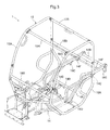
- FIG. 3 is a perspective view showing the configuration of the vehicle body frame
- FIG. 4 is a partial longitudinal cross-sectional side view showing the support structure for the engine, the HST, the transmission, the rear wheels, and other components;
- FIG. 5 is a partial lateral cross-sectional plan view showing the support structure for the engine, the HST, the transmission, the rear wheels, and other components;
- FIG. 6 is a partial plan view showing the manner in which the HST, the transmission, and the rear axle case are connected to the engine;
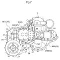
- FIG. 7 is a partial side view showing the manner in which the HST, the transmission, and the rear axle case are connected to the engine;
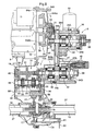
- FIG. 8 is a partial transverse cross-sectional plan view showing the structure for transmitting power from the engine to the rear axles;
- FIG. 9 is a partial transverse cross-sectional plan view showing the structure for transmitting power from the engine to the transmission;
- FIG. 10 is a partial transverse cross-sectional plan view showing the configuration of the transmission
- FIG. 11 is a partial longitudinal cross-sectional side view showing the structure for transmitting power from the engine to the rear axles;
- FIG. 12 is a partial transverse cross-sectional plan view showing the operational structure of the transmission
- FIG. 13 is a partial longitudinal cross-sectional side view showing the operational structure of the transmission
- FIG. 14 is a partial transverse cross-sectional plan view showing the configuration of the power take-off device
- FIG. 15 is a partial longitudinal cross-sectional side view showing the operational structure of the power take-off device
- FIG. 16 is a partial plan view showing the configuration of the rear suspension
- FIG. 17 is a partial side view showing the configuration of the rear suspension
- FIG. 18 is a partial longitudinal cross-sectional rear view showing the configuration of the rear suspension.
- FIG. 19 is a partial side view showing the configuration of the load-carrying platform.
- FIG. 1 is an overall side view of a multipurpose work vehicle.
- FIG. 2 is a schematic plan view showing the power transmission configuration of the multipurpose work vehicle.
- the multipurpose work vehicle comprises a pair of left and right front wheels 2 , a bottom cover 3 that doubles as a front fender, a hood 4 , and other components installed on the front of a vehicle body frame 1 , as shown in these drawings.
- a steering wheel 5 for steering the front wheels, a sofa-style seat 6 , and other components are provided to form a cab 7 .
- HST hydrostatic transmission
- a transmission 10 as a secondary transmission apparatus
- auxiliary frame 11 for supporting these components
- a pair of left and right rear wheels 12 a load-carrying platform 13 capable of dump-swinging, and other components.
- the vehicle body frame 1 is configured with a protective frame 15 or the like that forms a cab space and that is connected to a base frame 14 , as shown in FIG. 1 and FIGS. 3 through 5 .
- the base frame 14 is configured from a pair of left and right side members 14 A, a plurality of cross members 14 B that connect the side members, and other components.
- the left and right side members 14 A are bent so that the front sides are positioned below the cab 7 , and the rear sides are positioned behind the seat 6 .
- the protective frame 15 is configured from a pair of left and right side frames 15 S formed in the shape of a closed loop, a plurality of cross members 15 B connecting the side frames, and other components.
- power from the engine 8 is transmitted to the HST 9 , the power reduced by the HST 9 is transmitted to the transmission 10 , and the power reduced by the transmission 10 is divided in the transmission 10 into power for driving the rear wheels and power for driving the front wheels, as shown in FIGS. 1 , 2 , and 4 through 14 .
- the power for driving the rear wheels is transmitted to the left and right rear wheels 12 via a rear wheel differential device 17 provided within a transmission case 16 , which is a casing for the transmission 10 , and also via a pair of left and right rear axles 18 .
- the power for driving the front wheels is configured by a front wheel power take-off device 19 connected to and installed on the lower right front of the transmission case 16 , a first power transmission shaft 20 capable of expanding and contracting, a second power transmission shaft 21 , a differential device 22 for the front wheels, a pair of left and right third power transmission shafts 23 , a pair of left and right front axles (not shown), a plurality of universal couplings 24 that connect these components together, and other components.
- the left and right front wheels 2 are supported via the front axles (not shown) or the like on front axle cases 26 , which are independently suspended on the vehicle body frame 1 via a front suspension 25 , as shown in FIGS. 1 and 2 .
- a strut type independent suspension is used as the front suspension 25 .
- the left and right front axle cases 26 have wet multidisk brakes 27 A installed as front wheel brakes in their interiors.
- the left and right rear wheels 12 are supported on the transmission case 16 and on a pair of left and right rear axle cases 27 that extend outward to the left and right from the transmission case 16 , via the differential device 17 for the rear wheels, the rear axles 18 , and other components, as shown in FIGS. 1 , 2 , and 4 through 10 .
- the left and right rear axle cases 27 are supported on the auxiliary frame 11 along with the engine 8 , the HST 9 , the transmission 10 , and other components.
- Disc brakes 28 are installed as rear wheel brakes on the protruding ends of the left and right rear axle cases 27 .
- the auxiliary frame 11 is configured from a pair of left and right side members 11 A bent into L shapes, a plurality of cross members 11 B that connect the side members, a first plate 11 C for supporting the engine, a pair of left and right second plates 11 D for supporting the rear axle cases, a pair of left and right holders 11 E for holding the left and right rear axle cases 27 in place, and other components, as shown in FIGS. 4 , 5 , and 15 through 18 .
- the left and right holders 11 E are placed adjacent to the corresponding side members 11 A farther inward in the vehicle body.
- the auxiliary frame 11 is suspended on the vehicle body frame 1 via a rear suspension 29 .
- a five-linkage type rigid axle suspension is used as the rear suspension 29 .
- the engine 8 is mounted in a lateral orientation on the first plate 11 C of the auxiliary frame 11 so that an output shaft 31 that rotates integrally with a flywheel 30 of the engine lies along the left and right width direction of the vehicle body, and that an end plate 32 of the engine is coplanar with the outer right side of the vehicle body, as shown in FIGS. 1 , 2 , and 4 through 11 .
- An output gear 33 is fitted using a spline to the output shaft 31 .
- the HST 9 is configured with a hydraulic pump 35 , a primary hydraulic motor 36 , a secondary hydraulic motor 37 , and other components provided within a housing 34 of the HST.
- the housing 34 is configured from a port block 34 A, a first case 34 B that covers the hydraulic pump 35 , a second case 34 C that covers the primary hydraulic motor 36 , a third case 34 D that covers the secondary hydraulic motor 37 , and other components.
- An axial plunger type variable capacity pump is used as the hydraulic pump 35 .
- An axial plunger type constant capacity motor is used as the primary hydraulic motor 36 .
- An axial plunger type variable capacity motor is used as the secondary hydraulic motor 37 .
- the placement of the HST 9 is designed so that a pump shaft 38 as an input shaft thereof and a motor shaft 39 as an output shaft thereof lie along the left and right width direction of the vehicle body.
- the hydraulic pump 35 has an inclined plate 35 A that is operatively connected via a hydraulic servo mechanism (not shown) to a neutral two-way gear-change pedal (not shown) provided in the cab 7 .
- the hydraulic servo mechanism is configured so as to tilt the inclined plate 35 A of the hydraulic pump 35 on the basis of the depression of the gear-change pedal, wherein the inclined plate is tilted up to an angle corresponding to the amount by which the gear-change pedal is depressed.
- the gear-change operation of the HST 9 via the tilting of the pump inclined plate 35 A can be performed by depressing the gear-change pedal.
- an inclined plate 37 A is urged back into the neutral position by a pressure spring 40 , and is tilted against the urging of the pressure spring 40 by the action of a piston 41 .
- the piston 41 is connected to an oil supply passage (not shown) that supplies hydraulic fluid from the hydraulic pump 35 to the primary hydraulic motor 36 and the secondary hydraulic motor 37 .
- the internal pressure of the oil supply passage varies in accordance with fluctuation in the travelling load.
- the piston 41 tilts the inclined plate 37 A of the secondary hydraulic motor 37 against the urging of the pressure spring 40 up to an angle of inclination at which the internal pressure of the oil supply passage is balanced with the urging force of the pressure spring 40 .
- the internal pressure of the oil supply passage acts as reactive force that pushes the inclined plate 35 A of the hydraulic pump 35 back towards the neutral position.
- the rotational speed of the motor shaft 39 can thereby be reduced further, and a higher output torque corresponding to an even higher travelling load can be obtained.
- An input gear 42 that meshes with an output gear 33 of the engine 8 in a manner that enables reduced-gear power transmission is fitted using a spline to the left end of the pump shaft 38 .
- the pump shaft 38 of the HST 9 is connected to the output shaft 31 of the engine 8 via the output gear 33 and the input gear 42 .
- a cooling fan 43 is fitted using a spline to the right end of the pump shaft 38 .
- An oil filter 44 is installed in the first case 34 B.
- the transmission 10 is installed laterally in the auxiliary frame 11 , so that an input shaft 45 as a power transmission shaft of the transmission, a gear-change shaft 46 , a reverse shaft 47 , a first output shaft 48 for driving the rear wheels, and a second output shaft 49 for driving the front wheels lie along the left and right width direction of the vehicle body, as shown in FIGS. 1 , 2 , and 4 through 14 .
- the input shaft 45 is placed at the upper front of the transmission case 16 , and the right end of the input shaft is fitted using a spline to the motor shaft 39 of the HST 9 , as shown in FIGS. 8 through 14 .
- a first low-speed gear 50 , a first high-speed gear 51 , and a first reverse gear 52 are integrally formed on the input shaft 45 .
- the gear-change shaft 46 is placed in the transmission case 16 so as to be positioned behind and below the input shaft 45 .
- a second low-speed gear 53 that meshes with the first low-speed gear 50 , a second high-speed gear 54 that meshes with the first high-speed gear 51 , and a second reverse gear 55 are externally fitted and mounted on the gear-change shaft 46 in a manner that allows them to rotate relative to each other.
- a first shifter 56 that rotates integrally with the gear-change shaft 46 is disposed between the second low-speed gear 53 and the second high-speed gear 54 in the gear-change shaft 46 .
- the first shifter 56 is provided so as to be capable being slidably displaced among a low-speed forward position where the first shifter meshes with the second low-speed gear 53 , a high-speed forward position where the first shifter meshes with the second high-speed gear 54 , and a neutral position where the first shifter does not mesh with either of the gears.
- a second shifter 57 that rotates integrally with the gear-change shaft 46 is disposed at a location to the left of the second reverse gear 55 in the gear-change shaft 46 , and the second shifter 57 is provided so as to be capable of being slidably displaced between a reverse position where the second shifter meshes with the second reverse gear 55 , and a neutral position where the second shifter does not mesh with the second reverse gear 55 .
- a first reduction gear 58 is fitted using a spline with the right end of the gear-change shaft 46 .
- the reverse shaft 47 is placed in the transmission case 16 so as to be positioned behind and above the input shaft 45 , and also above and in front of the gear-change shaft 46 .
- a third reverse gear 59 that meshes with the first reverse gear 52 and the second reverse gear 55 is externally fitted and mounted to the reverse shaft 47 in a manner that enables relative rotation.
- the first output shaft 48 is placed in the transmission case 16 so as to be positioned behind and below the gear-change shaft 46 .
- a second reduction gear 60 that meshes with the first reduction gear 58 is fitted using a spline to the right end of the first output shaft 48 .
- a pinion gear 61 is formed integrally in the first output shaft 48 at a location to the left of the second reduction gear 60 .
- the pinion gear 61 meshes with a ring gear 62 provided to the rear wheel differential device 17 , which is positioned behind and below the pinion gear 61 .
- the second output shaft 49 is placed in the transmission case 16 so as to be positioned below the right front of the first output shaft 48 .
- a power transmission gear 63 that meshes with the second reduction gear 60 is formed integrally on the left end of the second output shaft 49 .
- a fork rod 64 and a camshaft 65 are longitudinally aligned while lying along the left and right width direction of the vehicle body, at a position that is behind the gear-change shaft 46 and above the differential device 17 in the transmission case 16 .
- a first guiding groove 65 A into which an engaging protuberance 66 A formed integrally on the first shifting fork 66 is engageably inserted, and a second guiding groove 65 B into which an engaging protuberance 67 A integrally formed on the second shifting fork 67 is engageably inserted, are formed in the camshaft 65 .
- the first guiding groove 65 A and the second guiding groove 65 B are formed so as to operatively guide the engaging protuberances 66 A, 67 A of the first shifting fork 66 and second shifting fork 67 as the camshaft 65 rotates.
- the first shifter 56 and second shifter 57 are thereby slidably displaced via the first shifting fork 66 and second shifting fork 67 into gear-change positions that correspond to the operating position of the camshaft 65 .
- An operating gear 68 and a disc 69 that rotate integrally with the camshaft 65 are externally fitted over the right end of the camshaft 65 .
- the operating arm 71 is operatively connected to a gear-change lever (not shown) provided to the cab 7 .
- a ball detent mechanism 73 is installed in the transmission case 16 , and this detent mechanism 73 engages with the through-holes 69 A to hold the camshaft 65 at the neutral position, the low-speed forward position, the high-speed forward position, and the reverse position.
- gear-change lever by operating the gear-change lever, it is possible to switch the gear-change state of the transmission 10 among a neutral state in which the first shifter 56 and the second shifter 57 are both held in a neutral position, a low-speed forward state in which the first shifter 56 is held in a low-speed forward position and the second shifter 57 is held in a neutral position, a high-speed forward state in which the first shifter 56 is held in a high-speed forward position and the second shifter 57 is held in a neutral position, and a reverse state in which the first shifter 56 is held in a neutral position and the second shifter 57 is held in a reverse position.
- the differential device 17 for the rear wheels is configured from a casing 74 that rotates integrally with the ring gear 62 , a support shaft 75 that is installed in the casing 74 and that lies orthogonal to the rear axles 18 , a pair of pinion gears 76 that fits externally over both ends of the support shaft 75 and that is capable of rotating relative to each other, a pair of left and right side gears 77 that are fitted inside the casing 74 to be capable of rotating relative to each other and that are fitted using splines on the corresponding rear axles 18 , and other components, as shown in FIGS. 8 and 10 .
- the transmission case 16 is equipped with a lock mechanism 78 that prevents the rear wheel differential device 17 from causing differential motion between the left and right rear wheels 12 in conjunction with the depression of a diff-lock pedal (not shown) provided in the cab 7 .
- the lock mechanism 78 is configured from a clutch 79 that is fitted using a spline to the right rear axle 18 and that prevents differential motion, a shifting fork 80 that slides integrally with the clutch 79 , a left-to-right oriented operating shaft 81 that supports the shifting fork 80 in a manner that allows the shifting fork 80 to rotate and slide in relative fashion, an operatively connecting pin 82 that operatively connects the shifting fork 80 with the operating shaft 81 , an operating arm 83 that is integrally and rotatably connected to the operating shaft 81 , and other components.
- a camshaft 80 A through which the operatively connecting pin 82 is engageably inserted is formed in the shifting fork 80 .
- the operatively connecting pin 82 rotates integrally with the operating shaft 81 .
- the operating arm 83 is operatively connected to the diff-lock pedal.
- the camshaft 80 A is formed so that the shifting fork 80 is slidably displaced in conjunction with the rotation of the operatively connecting pin 82 , whereby the clutch 79 is slidably displaced between a locked position of being interlocked with the casing 74 of the differential device 17 , and a lock-releasing position where the interlocking is released.
- the power take-off device 19 for the front wheels is configured from a front wheel power take-off clutch 84 that is fitted using a spline on the right end of the second output shaft 49 , a first bevel gear 85 that fits externally over the second output shaft 49 in a manner that allows relative rotation, a power take-off shaft 87 on which a second bevel gear 86 that meshes with the first bevel gear 85 is formed integrally, a casing 88 connected to the transmission case 16 so as to cover these components, and other components, as shown in FIGS. 14 and 15 .
- the casing 88 of the power take-off device 19 is provided with a drive switching mechanism 89 that switches between a four-wheel drive state in which the clutch 84 is interlocked with the first bevel gear 85 , and a two-wheel drive state in which the interlocking of the clutch 84 with the first bevel gear 85 is released, in conjunction with the operation of a switching lever (not shown) provided in the cab 7 .
- the drive switching mechanism 89 is configured from a vertically oriented operating shaft 90 that is supported on the casing 88 and that is capable of relative rotation, an operating arm 91 that is integrally and rotatably connected to the operating shaft 90 , and other components.
- An eccentric cam 92 is integrally formed on the lower end of the operating shaft 90 , and this eccentric cam 92 slidably displaces the clutch 84 between a power transmission position where the clutch is interlocked with the first bevel gear 85 , and a non-power transmission position where the interlocking is released, in conjunction with the rotation of the operating shaft 90 .
- the operating arm 91 is operatively connected to a switching lever.
- the transmission case 16 is configured from a left-side first case 93 and a right-side second case 94 , and these two cases are connected, thereby forming a housing space for housing the transmission 10 and the differential device 17 for the rear wheels, as shown in FIGS. 2 , 4 through 12 , and 14 .
- a protrusion 94 A that protrudes from an input unit 10 A of the transmission 10 towards an output unit 8 A of the engine 8 is integrally formed on the second case 94 .
- the protrusion 94 A is formed so as to have a first case portion 94 Aa that covers the flywheel 30 , the output gear 33 , and other components provided to the engine 8 ; a second case portion 94 Ab that covers the input gear 42 and other components provided to the pump shaft 38 ; and a third case portion 94 Ac that covers the primary hydraulic motor 36 of the HST 9 .
- the left end edge of the protrusion 94 A is a peripheral edge 94 a of the first case portion 94 Aa, and this peripheral edge 94 a is connected to the end plate 32 of the engine 8 .
- the right end edge of the protrusion 94 A is a peripheral edge 94 b of the second case portion 94 Ab, and this peripheral edge 94 b and a peripheral edge 94 c of the third case portion 94 Ac are connected to the port block 34 A of the HST 9 via a gasket 95 .
- the pump side of the port block 34 A of the HST 9 is thereby connected to the end plate 32 of the engine 8 via the first case portion 94 Aa and the second case portion 94 Ab of the transmission case 16 , and the motor side of the port block 34 A is connected to the input unit 10 A of the transmission 10 via the third case portion 94 Ac of the transmission case 16 , so that the port block 34 A extends between the engine 8 and the transmission 10 .
- the second case 94 of the transmission case 16 is also used as the second case 34 C of the HST 9 .
- the port block 34 A of the HST 9 also serves as the right side wall of the transmission case 16 , forming a housing space for housing the input gear 42 and other components between the transmission case 16 and the second case 94 .
- the structural components of the HST 9 and the transmission case 16 can thereby be reduced.
- the protrusion 94 A of the second case 94 in the transmission case 16 serves as a connecting member for connecting the engine 8 and transmission 10 , the configuration can be simplified and costs can be reduced by reducing the number of components, in comparison with cases in which a special connecting member is provided.
- the port block 34 A of the HST 9 functions as a reinforcing member for reinforcing the protrusion 94 A of the second case 94 that connects the engine 8 to the transmission 10 , the strength of the connection between the engine 8 and the transmission 10 can be improved without providing a special reinforcing member.
- the output shaft 31 of the engine 8 , the pump shaft 38 and motor shaft 39 of the HST 9 , and the power transmission shafts 45 to 49 of the transmission 10 are disposed in a left-to-right orientation while parallel to the left and right rear axles 18 .
- the output shaft 31 of the engine 8 , the pump shaft 38 and motor shaft 39 of the HST 9 , and the power transmission shafts 45 to 49 of the transmission 10 can thereby be disposed so as to have small longitudinal intervals between these components.
- the engine 8 , the HST 9 , and the transmission 10 can be placed in a manner that reduces their lengths in the longitudinal direction (or fore-and-aft direction) of the vehicle body.
- the transmission 10 can also be configured in a manner that reduces the length of the transmission in the longitudinal direction of the vehicle body. As a result, the entire length of the vehicle body can be reduced.
- the HST 9 can be disposed to the right of the laterally oriented engine 8 and transmission 10 so that, when viewed from the side, the HST 9 overlaps the engine 8 and transmission 10 .
- the entire length of the vehicle body can thereby be reduced in comparison with cases in which the engine 8 , the HST 9 , and the transmission 10 are aligned in a row along the longitudinal direction of the vehicle body.
- the rear suspension 29 is configured from a pair of left and right upper arms 96 and a pair of left and right lower arms 97 for positioning the left and right rear wheels 12 with respect to the longitudinal direction of the vehicle body; a single lateral rod 98 , a pair of left and right dampers 99 , and a pair of left and right coil springs 100 , for positioning the left and right rear wheels 12 with respect to the left-to-right direction of the vehicle body; and other components, as shown in FIGS. 1 , 3 through 5 , and 16 through 18 .
- the left and right upper arms 96 and the left and right lower arms 97 are disposed in a longitudinal orientation so as to be positioned directly below the side members 14 A of the base frame 14 .
- Connecting bosses 96 A, 96 B, 97 A, 97 B are integrally mounted on both ends of the left and right upper arms 96 and lower arms 97 .
- the front bosses 96 A in the left and right upper arms 96 are connected, via rubber bushes 101 , left-to-right oriented bolts 102 , and the like, to brackets 14 C provided at the rear parts of the left and right side members 14 A in the base frame 14 .
- the rear bosses 96 B are connected, via rubber bushes 101 , left-to-right oriented bolts 102 , and the like, to brackets 11 F provided at the top ends of the corresponding side members 11 A in the auxiliary frame 11 .
- the front bosses 97 A in the left and right lower arms 97 are connected, via rubber bushes 101 , left-to-right oriented bolts 102 , and the like, to brackets 14 D provided at the longitudinal middles of the left and right side members 14 A in the base frame 14 .
- the rear bosses 97 B are connected, via rubber bushes 101 , left-to-right oriented bolts 102 , and the like, to brackets 11 G provided at the front ends of the corresponding side members 11 A in the auxiliary frame 11 .
- the left and right upper arms 96 and the left and right lower arms 97 are set so that the left and right lower arms 97 are longer than the left and right upper arms 96 , that the left and right upper arms 96 are positioned farther to the rear of the vehicle body than the left and right lower arms 97 , and that the angles of the left and right upper arms 96 in relation to the vehicle body frame 1 are greater than the angles of the left and right lower arms 97 in relation to the vehicle body frame 1 .
- a lateral rod 98 is disposed in a left-to-right orientation at a position in the vehicle body that is farther inward than the rear end of the base frame 14 .
- Connecting bosses 98 A, 98 B are integrally mounted at both ends of the lateral rod 98 .
- the left boss 98 A is connected, via a rubber bush 103 , a longitudinally oriented bolt 104 , and the like, to a bracket 14 E provided at the rear end of the left side member 14 A in the base frame 14 .
- the right boss 98 B is connected, via a rubber bush 103 , a longitudinally oriented bolt 104 , and the like, to a bracket 11 H provided at the top end of the right side member 11 A in the auxiliary frame 11 .
- Connecting bosses 99 A, 99 B are integrally mounted on both ends of the left and right dampers 99 .
- the top bosses 99 A are connected, via rubber bushes 105 , longitudinally oriented bolts 106 , and the like, to brackets 14 F that project into the vehicle body in the rear parts of the side members 14 A in the base frame 14 .
- the bottom bosses 99 B are connected to corresponding holders 11 E in the auxiliary frame 11 via rubber bushes 105 , longitudinally oriented bolts 106 , and the like.
- Coil springs 100 are externally fitted over the dampers 99 so that shocks from the road are absorbed by the coil springs 100 , and that the movement of the coil springs 100 is controlled by the dampers 99 (periodic vibrations of the coil springs 100 converge sooner).
- the rear suspension 29 is configured so that the left and right upper arms 96 and lower arms 97 overlap with the left and right side members 14 A of the base frame 14 as seen in a plan view, the lateral rod 98 is disposed at the rear end part which is farther inward in the vehicle body than the rear end of the base frame 14 , and the left and right dampers 99 and coil springs 100 are placed adjacent to the corresponding side members 14 A of the base frame 14 and are positioned farther inward in the vehicle body than the left and right side members 14 A.
- the engine 8 , the HST 9 the transmission 10 , and other components can also be installed in the auxiliary frame 11 in a suitable manner in which there is enough space from the base frame 14 and other components. It is thereby possible to pre-emptively prevent problems in which the engine 8 , the HST 9 , the transmission 10 , and other components come into contact with the base frame 14 and other components when the rear suspension 29 reduces vibrations or shocks from the road.
- the left and right rear wheels 12 are displaced in relation to the engine 8 , the HST 9 , and the transmission 10 when the rear suspension 29 reduces vibrations or shocks from the road. Therefore, universal couplings or the like that allow the left and right rear wheels 12 to be displaced in relation to the engine 8 , the HST 9 , and the transmission 10 must be installed in the system for transmitting power to the left and right rear wheels 12 .
- the engine 8 , the HST 9 , and the transmission 10 are mounted together with the left and right rear wheels 12 in the auxiliary frame 11 suspended on the base frame 14 via the rear suspension 29 in this multipurpose work vehicle.
- the engine 8 , the HST 9 , and the transmission 10 can thereby be displaced integrally together with the left and right rear wheels 12 in relation to the base frame 14 when the rear suspension 29 reduces vibrations or shocks from the road. Therefore, universal couplings or the like that allow the left and right rear wheels 12 to be displaced in relation to the engine 8 , the HST 9 , and the transmission 10 do not need to be installed in the system for transmitting power to the left and right rear wheels 12 .
- the power transmission structure can be simplified and costs can be reduced by reducing the number of components through placement of the engine 8 , the HST 9 , and the transmission 10 together with the left and right rear wheels 12 in the auxiliary frame 11 suspended on the base frame 14 via the rear suspension 29 .
- rubber bushes 101 , 103 , 105 are placed between the base frame 14 and the rear suspension 29 and also between the auxiliary frame 11 and the rear suspension 29 , whereby twisting to the left and right can be absorbed by these rubber bushes 101 , 103 , 105 .
- an inexpensive rigid axle suspension with a simple structure can be used as the rear suspension 29 , and a smoother ride can be provided.
- the engine 8 Since the engine 8 is supported in a vibration-proof manner on the base frame 14 via the rear suspension 29 , vibration from the engine 8 can be prevented from reaching the base frame 14 without providing any engine-specific anti-vibration rubber components. Moreover, in cases in which engine-specific anti-vibration rubber components are provided, the power transmission system running from the engine 8 to the transmission 10 must be provided with hydraulic couplings or the like for allowing relative displacement therein, but no such universal couplings or the like are needed in this multipurpose work vehicle. In other words, the configuration can be further simplified and costs further reduced by reducing the number of components, and an even smoother ride can be ensured.
- a pair of left and right brackets 107 is installed on the bottom of the load-carrying platform 13 at a position that is behind the longitudinal middle, as shown in FIG. 19 .
- the left and right brackets 107 are externally fitted over left-to-right oriented support shafts 108 provided at the rear ends of the base frame 14 in a manner that allows the brackets 107 to rotate relative to each other.
- Four rubber mounts 109 that are secured and supported by the base frame 14 are installed on the bottom of the load-carrying platform 13 .
- a pair of left and right swinging links 110 is connected at one end to the longitudinal middle in the bottom of the load-carrying platform 13 .
- Long holes 110 A are formed at the other ends of the left and right swinging links 110 , and left-to-right oriented stopping pins 111 provided at the rear of the base frame 14 are engageably inserted through these long holes 110 A.
- Handles 112 are installed on the left and right sides at the front of the load-carrying platform 13 .
- Concavities 110 B that can engage with the stopping pins 111 are formed so as to recess upwards at the front ends of the long holes 110 A in the swinging links 110 .
- the concavities 110 B engage with the support shafts 108 that have come into contact with the front edges of the long holes 110 A, whereby the load-carrying platform 13 can be held at the dumping position.
- the position of the load-carrying platform 13 can be switched from dumping to carrying by grasping the handles 112 and releasing the engagement between the concavities 110 B of the swinging links 110 and the stopping pins 111 .
- the transmission 10 is equipped with a detection mechanism 113 for detecting the neutral state of the transmission 10 , as shown in FIG. 13 .
- the detection mechanism 113 is configured from a neutral detection concavity 69 B formed by recessing the external periphery of the disc 69 that rotates integrally with the camshaft 65 , and a switch 114 that is switched to a closed state by the engageable insertion of an actuator 114 A into the concavity 69 B.
- the switch 114 is a structural element of a startup restraint circuit (not shown) that restrains the engine 8 from starting up.
- the startup restraint circuit is configured so as to prevent the engine 8 from starting up in cases in which the switch 114 is open; i.e., in cases in which the transmission 10 is in neutral.
- the work vehicle may be a tractor, a lawn mower, a rice-planter, a combine harvester or the like.
- the work vehicle may be configured as a four-wheel drive vehicle in which the engine 8 and HST 0 and the transmission device 10 are placed in the front of the vehicle body, and the power from the engine 8 is transmitted via the HST 9 and the transmission device 10 to the left and right front wheels 2 and the left and right rear wheels 12 .
- the work vehicle may be configured as a rear-wheel drive vehicle in which the engine 8 and the HST 9 and the transmission device 10 are placed in the rear of the vehicle body, and the power from the engine 8 is transmitted via the HST 9 and the transmission devices 10 to the left and right rear wheels 12 .
- the work vehicle may be configured as a front-wheel drive vehicle in which the engine 8 and the HST 9 and the transmission device 10 are placed in the front of the vehicle body, and the power from the engine 8 is transmitted via the HST 9 and the transmission devices 10 to the left and right front wheels 2 .
- a transmission that does not include the secondary hydraulic motor 37 may be used for the HST 9 .
- the HST 9 may have a casing that extends from the hydraulic pump side to the hydraulic motor side to cover the hydraulic pump 35 and the primary hydraulic motor 36 or the secondary hydraulic motor 37 .
- the case of the transmission 10 may be of the type that does not have the protrusion 94 A that protrudes from the input unit 10 a of the transmission to the output 8 A of the engine 8 .
- the output shaft 31 of the engine may be coupled with the pump shaft 38 of the HST 9 by spline coupling.
- the input shaft 45 of the transmission 10 may be coupled to the motor shaft 39 of the HST 9 by a transmission gear.
- the engine 8 and the transmission 10 may be connected to each other only by the housing 34 of the HST 9 .
Landscapes
- Engineering & Computer Science (AREA)
- Mechanical Engineering (AREA)
- Transportation (AREA)
- Chemical & Material Sciences (AREA)
- Combustion & Propulsion (AREA)
- Power Engineering (AREA)
- General Engineering & Computer Science (AREA)
- Life Sciences & Earth Sciences (AREA)
- Sustainable Development (AREA)
- Sustainable Energy (AREA)
- Motor Power Transmission Devices (AREA)
Applications Claiming Priority (2)
| Application Number | Priority Date | Filing Date | Title |
|---|---|---|---|
| JP2007-234293 | 2007-09-10 | ||
| JP2007234293A JP5016421B2 (ja) | 2007-09-10 | 2007-09-10 | 作業車の伝動構造 |
Publications (2)
| Publication Number | Publication Date |
|---|---|
| US20090065279A1 US20090065279A1 (en) | 2009-03-12 |
| US8181731B2 true US8181731B2 (en) | 2012-05-22 |
Family
ID=39328376
Family Applications (1)
| Application Number | Title | Priority Date | Filing Date |
|---|---|---|---|
| US12/051,832 Active 2030-02-16 US8181731B2 (en) | 2007-09-10 | 2008-03-19 | Drive train for work vehicle |
Country Status (3)
| Country | Link |
|---|---|
| US (1) | US8181731B2 (ja) |
| JP (1) | JP5016421B2 (ja) |
| GB (1) | GB2452581B (ja) |
Cited By (13)
| Publication number | Priority date | Publication date | Assignee | Title |
|---|---|---|---|---|
| US20130146384A1 (en) * | 2010-08-31 | 2013-06-13 | Komatsu Ltd. | Forklift |
| US20140014422A1 (en) * | 2011-03-29 | 2014-01-16 | Komatsu Ltd. | Electric forklift |
| US20150251531A1 (en) * | 2012-07-27 | 2015-09-10 | Aisin Aw Co., Ltd. | Vehicle drive device |
| US20170001519A1 (en) * | 2015-07-02 | 2017-01-05 | Kubota Corporation | Utility Work Vehicle |
| US9649924B2 (en) | 2013-03-22 | 2017-05-16 | Kubota Corporation | Work/utility vehicle |
| US20170174076A1 (en) * | 2014-04-25 | 2017-06-22 | Poclain Hydraulics Industrie | Drive assembly for a motor vehicle drive shaft |
| US20190118630A1 (en) * | 2017-10-23 | 2019-04-25 | Audi Ag | Drive device |
| US10391849B2 (en) * | 2014-04-25 | 2019-08-27 | Aisin Aw Co., Ltd. | Vehicle drive device |
| US10495164B2 (en) * | 2015-09-24 | 2019-12-03 | Hitachi Construction Machinery Co., Ltd. | Wheel type construction machine |
| US11097613B2 (en) | 2010-04-06 | 2021-08-24 | Polaris Industries Inc. | Vehicle |
| US20220221036A1 (en) * | 2020-10-05 | 2022-07-14 | Kubota Corporation | Multiple-Purpose Vehicle |
| US20220315109A1 (en) * | 2019-09-20 | 2022-10-06 | Kubota Corporation | Work Vehicle |
| US11485227B2 (en) | 2020-03-16 | 2022-11-01 | Kubota Corporation | Work vehicle |
Families Citing this family (14)
| Publication number | Priority date | Publication date | Assignee | Title |
|---|---|---|---|---|
| JP2009073371A (ja) * | 2007-09-21 | 2009-04-09 | Kanzaki Kokyukoki Mfg Co Ltd | 車両の伝動装置 |
| US9162558B2 (en) * | 2009-06-15 | 2015-10-20 | Polaris Industries Inc. | Electric vehicle |
| US9975424B2 (en) * | 2015-05-15 | 2018-05-22 | Cnh Industrial America Llc | Dropbox assembly for transmission of work vehicle |
| CN105196862A (zh) * | 2015-10-20 | 2015-12-30 | 无锡格莱德科技有限公司 | 一种带变速驱动轴的汽车动力传动系统 |
| CA3138437A1 (en) * | 2016-06-14 | 2017-12-21 | Polaris Industries Inc. | Hybrid utility vehicle |
| JP6552459B2 (ja) * | 2016-06-27 | 2019-07-31 | 株式会社クボタ | 作業車 |
| CN106122421A (zh) * | 2016-08-31 | 2016-11-16 | 温岭市明华齿轮有限公司 | 一种齿轮变速箱 |
| JP6746544B2 (ja) * | 2017-08-31 | 2020-08-26 | 日立建機株式会社 | 建設機械 |
| US10780770B2 (en) | 2018-10-05 | 2020-09-22 | Polaris Industries Inc. | Hybrid utility vehicle |
| JP7178321B2 (ja) * | 2019-05-15 | 2022-11-25 | 株式会社ササキコーポレーション | 自走式作業機 |
| US11370266B2 (en) | 2019-05-16 | 2022-06-28 | Polaris Industries Inc. | Hybrid utility vehicle |
| JP7211928B2 (ja) * | 2019-12-04 | 2023-01-24 | 株式会社クボタ | 多目的車両 |
| CN112178161B (zh) * | 2020-08-27 | 2022-06-03 | 东风汽车集团有限公司 | 一种带独立撞块的变速箱悬置 |
| CN114352698A (zh) * | 2022-02-22 | 2022-04-15 | 浙江康利铖机电有限公司 | 一种零转向液压驱动桥 |
Citations (6)
| Publication number | Priority date | Publication date | Assignee | Title |
|---|---|---|---|---|
| JPH04283130A (ja) | 1991-03-11 | 1992-10-08 | Honda Motor Co Ltd | エンジン用出力装置 |
| JP2002243018A (ja) | 2001-02-14 | 2002-08-28 | Sauer-Danfoss-Daikin Ltd | 液圧機械式変速装置及びその変速装置を搭載した車両 |
| JP2004050954A (ja) | 2002-07-19 | 2004-02-19 | Kubota Corp | 作業車の伝動構造 |
| JP2005178783A (ja) | 2005-03-18 | 2005-07-07 | Kubota Corp | 作業車 |
| US7089824B2 (en) * | 2003-02-24 | 2006-08-15 | Kubota Corporation | Traveling transmission apparatus for work vehicle |
| US7093685B1 (en) * | 2002-10-04 | 2006-08-22 | Hydro-Gear Limited Partnership | Utility vehicle having hydrostatic drive |
Family Cites Families (4)
| Publication number | Priority date | Publication date | Assignee | Title |
|---|---|---|---|---|
| JPS60252867A (ja) * | 1984-12-11 | 1985-12-13 | Toyota Motor Corp | ベルト式無段変速装置と補助変速装置を備えた変速機 |
| JPS6146718A (ja) * | 1984-08-13 | 1986-03-07 | Iseki & Co Ltd | コンバインの走行伝導装置 |
| JP2000272364A (ja) * | 1999-03-25 | 2000-10-03 | Kubota Corp | 水田作業機 |
| JP2002192972A (ja) * | 2000-12-27 | 2002-07-10 | Kubota Corp | 作業機の走行用伝動装置 |
-
2007
- 2007-09-10 JP JP2007234293A patent/JP5016421B2/ja not_active Expired - Fee Related
-
2008
- 2008-03-18 GB GB0805057A patent/GB2452581B/en active Active
- 2008-03-19 US US12/051,832 patent/US8181731B2/en active Active
Patent Citations (7)
| Publication number | Priority date | Publication date | Assignee | Title |
|---|---|---|---|---|
| JPH04283130A (ja) | 1991-03-11 | 1992-10-08 | Honda Motor Co Ltd | エンジン用出力装置 |
| JP2002243018A (ja) | 2001-02-14 | 2002-08-28 | Sauer-Danfoss-Daikin Ltd | 液圧機械式変速装置及びその変速装置を搭載した車両 |
| US6848530B2 (en) * | 2001-02-14 | 2005-02-01 | Sauer-Danfoss-Daikin Ltd. | Hydromechanical speedchange device and vehicle having speed change device mounted thereon |
| JP2004050954A (ja) | 2002-07-19 | 2004-02-19 | Kubota Corp | 作業車の伝動構造 |
| US7093685B1 (en) * | 2002-10-04 | 2006-08-22 | Hydro-Gear Limited Partnership | Utility vehicle having hydrostatic drive |
| US7089824B2 (en) * | 2003-02-24 | 2006-08-15 | Kubota Corporation | Traveling transmission apparatus for work vehicle |
| JP2005178783A (ja) | 2005-03-18 | 2005-07-07 | Kubota Corp | 作業車 |
Cited By (21)
| Publication number | Priority date | Publication date | Assignee | Title |
|---|---|---|---|---|
| US11097613B2 (en) | 2010-04-06 | 2021-08-24 | Polaris Industries Inc. | Vehicle |
| US20130146384A1 (en) * | 2010-08-31 | 2013-06-13 | Komatsu Ltd. | Forklift |
| US8573349B2 (en) * | 2010-08-31 | 2013-11-05 | Komatsu Ltd. | Forklift |
| US20140014422A1 (en) * | 2011-03-29 | 2014-01-16 | Komatsu Ltd. | Electric forklift |
| US8936130B2 (en) * | 2011-03-29 | 2015-01-20 | Komatsu Ltd. | Electric forklift |
| US9358870B2 (en) * | 2012-07-27 | 2016-06-07 | Aisin Aw Co., Ltd. | Vehicle drive device |
| US20150251531A1 (en) * | 2012-07-27 | 2015-09-10 | Aisin Aw Co., Ltd. | Vehicle drive device |
| US9649924B2 (en) | 2013-03-22 | 2017-05-16 | Kubota Corporation | Work/utility vehicle |
| US10391849B2 (en) * | 2014-04-25 | 2019-08-27 | Aisin Aw Co., Ltd. | Vehicle drive device |
| US20170174076A1 (en) * | 2014-04-25 | 2017-06-22 | Poclain Hydraulics Industrie | Drive assembly for a motor vehicle drive shaft |
| US10675971B2 (en) * | 2014-04-25 | 2020-06-09 | Poclain Hydraulics Industrie | Drive assembly for a motor vehicle drive shaft |
| US9849779B2 (en) * | 2015-07-02 | 2017-12-26 | Kubota Corporation | Utility work vehicle |
| US20170001519A1 (en) * | 2015-07-02 | 2017-01-05 | Kubota Corporation | Utility Work Vehicle |
| US10495164B2 (en) * | 2015-09-24 | 2019-12-03 | Hitachi Construction Machinery Co., Ltd. | Wheel type construction machine |
| US20190118630A1 (en) * | 2017-10-23 | 2019-04-25 | Audi Ag | Drive device |
| US10773581B2 (en) * | 2017-10-23 | 2020-09-15 | Audi Ag | Drive device |
| US20220315109A1 (en) * | 2019-09-20 | 2022-10-06 | Kubota Corporation | Work Vehicle |
| US11926363B2 (en) * | 2019-09-20 | 2024-03-12 | Kubota Corporation | Work vehicle |
| US11485227B2 (en) | 2020-03-16 | 2022-11-01 | Kubota Corporation | Work vehicle |
| US20220221036A1 (en) * | 2020-10-05 | 2022-07-14 | Kubota Corporation | Multiple-Purpose Vehicle |
| US11566694B2 (en) * | 2020-10-05 | 2023-01-31 | Kubota Corporation | Multiple-purpose vehicle |
Also Published As
| Publication number | Publication date |
|---|---|
| GB0805057D0 (en) | 2008-04-16 |
| GB2452581B (en) | 2009-12-02 |
| US20090065279A1 (en) | 2009-03-12 |
| JP5016421B2 (ja) | 2012-09-05 |
| GB2452581A (en) | 2009-03-11 |
| JP2009067081A (ja) | 2009-04-02 |
Similar Documents
| Publication | Publication Date | Title |
|---|---|---|
| US8181731B2 (en) | Drive train for work vehicle | |
| US7600769B2 (en) | Frame structure for work vehicle | |
| JP3824665B2 (ja) | 作業車用トランスミッション | |
| US7143858B2 (en) | Transmission for a working vehicle and vehicle | |
| US9487085B2 (en) | Transaxle and working vehicle equipped with the transaxle | |
| KR102178602B1 (ko) | 작업 차량 | |
| EP1584511B1 (en) | Vehicle power transmission system | |
| JP4966138B2 (ja) | 作業車の車体構造 | |
| JP2009214818A (ja) | 作業車両 | |
| JP5069524B2 (ja) | 作業車の車体構造 | |
| JP2004068857A (ja) | 走行作業車の差動装置 | |
| JP6488530B2 (ja) | クローラトラクタ | |
| JP3943448B2 (ja) | クローラ形トラクタ | |
| KR102043536B1 (ko) | 크롤러 트랙터 | |
| JP2000142141A (ja) | 乗用田植機のトランスミッション | |
| JP6468514B2 (ja) | クローラトラクタ | |
| JP4654462B2 (ja) | 車両伝動装置 | |
| JP3621403B2 (ja) | 作業車用トランスミッション | |
| JP3693586B2 (ja) | 作業車の車体構造 | |
| JP2007290705A (ja) | 作業車輌 | |
| JP2007203972A (ja) | 走行用伝動機構からの動力取出構造 | |
| JP2007083886A (ja) | 自動二輪車 | |
| JP6552936B2 (ja) | 作業車両 | |
| JP6515008B2 (ja) | 作業車両 | |
| JP4039621B2 (ja) | クローラ形トラクタ |
Legal Events
| Date | Code | Title | Description |
|---|---|---|---|
| AS | Assignment |
Owner name: KUBOTA CORPORATION, JAPAN Free format text: ASSIGNMENT OF ASSIGNORS INTEREST;ASSIGNORS:BESSHO, HIROKI;HORIUCHI, YOSHIFUMI;SHIMADA, HIROSHI;AND OTHERS;REEL/FRAME:021210/0228;SIGNING DATES FROM 20080515 TO 20080520 Owner name: KUBOTA CORPORATION, JAPAN Free format text: ASSIGNMENT OF ASSIGNORS INTEREST;ASSIGNORS:BESSHO, HIROKI;HORIUCHI, YOSHIFUMI;SHIMADA, HIROSHI;AND OTHERS;SIGNING DATES FROM 20080515 TO 20080520;REEL/FRAME:021210/0228 |
|
| STCF | Information on status: patent grant |
Free format text: PATENTED CASE |
|
| FEPP | Fee payment procedure |
Free format text: PAYOR NUMBER ASSIGNED (ORIGINAL EVENT CODE: ASPN); ENTITY STATUS OF PATENT OWNER: LARGE ENTITY |
|
| FPAY | Fee payment |
Year of fee payment: 4 |
|
| MAFP | Maintenance fee payment |
Free format text: PAYMENT OF MAINTENANCE FEE, 8TH YEAR, LARGE ENTITY (ORIGINAL EVENT CODE: M1552); ENTITY STATUS OF PATENT OWNER: LARGE ENTITY Year of fee payment: 8 |
|
| MAFP | Maintenance fee payment |
Free format text: PAYMENT OF MAINTENANCE FEE, 12TH YEAR, LARGE ENTITY (ORIGINAL EVENT CODE: M1553); ENTITY STATUS OF PATENT OWNER: LARGE ENTITY Year of fee payment: 12 |