US8089342B2 - Electronic key system and method - Google Patents
Electronic key system and method Download PDFInfo
- Publication number
- US8089342B2 US8089342B2 US12/000,788 US78807A US8089342B2 US 8089342 B2 US8089342 B2 US 8089342B2 US 78807 A US78807 A US 78807A US 8089342 B2 US8089342 B2 US 8089342B2
- Authority
- US
- United States
- Prior art keywords
- mobile unit
- vehicle device
- search
- search signal
- vehicle
- Prior art date
- Legal status (The legal status is an assumption and is not a legal conclusion. Google has not performed a legal analysis and makes no representation as to the accuracy of the status listed.)
- Expired - Fee Related, expires
Links
Images


Classifications
-
- E—FIXED CONSTRUCTIONS
- E05—LOCKS; KEYS; WINDOW OR DOOR FITTINGS; SAFES
- E05B—LOCKS; ACCESSORIES THEREFOR; HANDCUFFS
- E05B49/00—Electric permutation locks; Circuits therefor ; Mechanical aspects of electronic locks; Mechanical keys therefor
-
- B—PERFORMING OPERATIONS; TRANSPORTING
- B60—VEHICLES IN GENERAL
- B60R—VEHICLES, VEHICLE FITTINGS, OR VEHICLE PARTS, NOT OTHERWISE PROVIDED FOR
- B60R25/00—Fittings or systems for preventing or indicating unauthorised use or theft of vehicles
- B60R25/20—Means to switch the anti-theft system on or off
- B60R25/24—Means to switch the anti-theft system on or off using electronic identifiers containing a code not memorised by the user
-
- B—PERFORMING OPERATIONS; TRANSPORTING
- B60—VEHICLES IN GENERAL
- B60R—VEHICLES, VEHICLE FITTINGS, OR VEHICLE PARTS, NOT OTHERWISE PROVIDED FOR
- B60R25/00—Fittings or systems for preventing or indicating unauthorised use or theft of vehicles
- B60R25/10—Fittings or systems for preventing or indicating unauthorised use or theft of vehicles actuating a signalling device
- B60R25/102—Fittings or systems for preventing or indicating unauthorised use or theft of vehicles actuating a signalling device a signal being sent to a remote location, e.g. a radio signal being transmitted to a police station, a security company or the owner
-
- E—FIXED CONSTRUCTIONS
- E05—LOCKS; KEYS; WINDOW OR DOOR FITTINGS; SAFES
- E05B—LOCKS; ACCESSORIES THEREFOR; HANDCUFFS
- E05B47/00—Operating or controlling locks or other fastening devices by electric or magnetic means
Definitions
- the present invention relates to an electronic key system and method.
- a conventional electronic key system for a vehicle is made up of an in-vehicle device that is mounted in a vehicle, and a mobile unit that is carried by a user of the vehicle.
- This electronic key system executes the control of the lock/unlock of doors or engine starting when authentication of the mobile unit is approved via radio communication between the in-vehicle device and the mobile unit, even if a mechanical key is not operated.
- JP 2005-220728A proposes a mobile unit locating device that is used when the user wants to locate the missing mobile unit. However, even when this mobile unit locating device is used, it is not frequently found at what specific location the mobile unit is at although it is possible to roughly know a certain area in which the mobile unit exists.
- the mobile unit when the mobile unit is placed in a pocket of clothing or in a bag of a user, even if the area in which the mobile unit exists can be specified by using the mobile unit locating device, the user cannot sometimes find where the mobile unit exists within the area. In this case, when there are a lot of possible locations in which the mobile unit may be placed, user must search all those locations for the mobile unit, and therefore cannot find the mobile unit easily. Also, for example, when the mobile unit is lost outdoors at night, even if the area in which the mobile unit exists can be specified by using the mobile unit locating device, where the mobile unit is located cannot be found in a dark location with no light.
- an electronic key system and method controls a door of a control object such as a vehicle.
- an in-object device provided in the control object communicates with a mobile unit carried by a user thereby to conduct an authentication of the mobile unit.
- the in-object device transmits a search signal from the in-object device for locating the mobile unit.
- the mobile unit receives the search signal, it issues a notification indicating its existence.
- FIG. 1 is a block diagram showing an electronic key system according to a first embodiment of the present invention
- FIG. 2 is a flowchart showing a locating process according to the first embodiment
- FIGS. 3A and 3B are flowcharts showing a response process and a notifying process according to the first embodiment
- FIG. 4 is a block diagram showing an electronic key system according to a second embodiment of the present invention.
- FIG. 5 is a flowchart showing a locating process according to the second embodiment
- FIG. 6 is a flowchart showing a notifying process according to the second embodiment
- FIG. 7 is a flowchart showing a cancel process (No. 1) according to the second embodiment
- FIG. 8 is a flowchart showing a cancel process (No. 2) according to the second embodiment.
- FIGS. 9A and 9B are block diagrams showing a modified example of an electronic key system according to the second embodiment.
- an electronic key system includes an in-vehicle device 1 that is mounted in a vehicle, and a mobile unit 2 carried by a user of the vehicle.
- This electronic key system may have both a smart entry function of executing the control of unlocking of doors when the mobile unit 2 that is carried by the user enters a radio communication area around the vehicle, and a remote keyless entry function of executing the control of locking or unlocking the doors according to a button operation of the mobile unit by the user at a place away from the vehicle. Both the smart entry function and the remote keyless entry function are known well in the art.
- the in-vehicle device 1 includes a microcomputer 10 , a low frequency (LF) transmitter unit 11 , an ultra-high frequency (UHF) receiver unit 12 , an engine switch 15 , door antennas 16 provided on each door of the vehicle, a vehicle in-room antenna 17 provided in a passenger compartment, an in-trunk antenna 18 provided inside a trunk, and an out-trunk antenna 19 provided outside the trunk.
- LF low frequency
- UHF ultra-high frequency
- the LF transmitter unit 11 is means (first transmitter) for transmitting a radio signal to the mobile unit 2 by electric waves of an LF band (first frequency band).
- the radio signal that is transmitted from the LF transmitter unit 11 reaches the respectively limited communication areas through the door antennas 16 , the in-room antenna 17 , the in-room antenna 18 , and the out-trunk antenna 19 .
- the UHF receiver unit 12 is means for receiving a radio signal that are transmitted from the mobile unit 2 by electric waves of a UHF band (second frequency band).
- the engine switch 15 is operable by the user to start an engine.
- the microcomputer 10 checks whether engine starting is allowed or not. When the engine starting is allowed, an engine start signal is transmitted from the microcomputer 10 to an engine control system (not shown).
- the mobile unit 2 has a control IC 20 , an LF receiver unit 21 , a UHF transmitter unit 22 , push switches 25 , 26 , a display unit 27 , and a buzzer 28 .
- the LF receiver unit 21 is means (first receiver) for receiving the radio signal that is transmitted from the in-vehicle device 1 by the electric waves of the LF band.
- the UHF transmitter unit 22 is means (first transmitter) for transmitting a radio signal to the in-vehicle device 1 by the electric waves of the UHF band.
- the push switches 25 and 26 are provided as keys that are triggers for mainly using the remote keyless entry function. In the case of conducting one-push operation, the push switch 25 locks the doors whereas the push switch 26 unlocks the doors.
- the display unit 27 is made up of an LCD and an LED. When the mobile unit 2 is located, the display unit 27 is activated to blink the LED in the mobile unit 2 to notify the presence of the mobile unit 2 by means of light. The buzzer 28 blows to notify the presence of the mobile unit by means of sound. That is, both of the display unit 27 and the buzzer 28 are provided as notifying means.
- in-vehicle device 1 For executing the smart entry function, respective portions of in-vehicle device 1 are operated while being controlled by microcomputer 10 , and LF transmitter unit 11 periodically transmits a transmission request signal under control of microcomputer 10 . Respective portions of mobile unit 2 are operated while being controlled by control IC 20 . When mobile unit 2 enters either one of the radio communication areas of antennas 16 to 19 that can receive the transmission request signal from the LF transmitter unit 11 , receiver unit 21 receives the transmission request signal.
- a signal transmission using the electric waves of the LF band is conducted between the LF transmitter unit 11 and the LF receiver unit 21 .
- the detection area of the mobile unit 2 is limited to inside of and the outside periphery of the vehicle.
- the detection area can be limited to the vicinity of the doors, the vehicle compartment, inside the trunk, and outside the trunk. As a result, it is possible to detect where the mobile unit 2 exists, and to prevent the mobile unit 2 from being locked in, for example, when the mobile unit 2 is left in the compartment or trunk.
- the UHF transmitter unit 22 transmits a response signal including an identification code (ID) specific to the vehicle corresponding to the mobile unit 2 . Then, at the in-vehicle device 1 , the UHF receiver unit 12 receives the response signal from the mobile unit 2 .
- ID an identification code
- a signal transmission using the electric waves of the UHF band is conducted between the UHF transmitter unit 22 and the UHF receiver unit 12 . This is because a predetermined communication distance is obtained even if the output level of the mobile unit 2 is relatively small, and the response signal can be more surely transmitted to the in-vehicle device 1 .
- the microcomputer 10 at the in-vehicle device 1 checks whether the ID included in the response signal agrees with the ID that is stored in the microcomputer 10 or not, for authentication. When both Ids agree, the unlocking of the doors is allowed.
- a known control in the electronic key system of this type is executed. For example, when it is detected that the user or somebody else touched a door knob according to a signal from a touch sensor (not shown) which is disposed in the door knob outside of a driver's door in an unlocking enabled state, the microcomputer 10 transmits an unlock signal to a door control system. As a result, a door lock motor (not shown) is driven so that all of the doors are unlocked. In addition, other controls may be conducted such that the engine starting is enabled.
- the in-vehicle device 1 executes a mobile unit locating operation in a manner shown in FIGS. 2 and 3 .
- a search process that is executed in the in-vehicle device 1 will be described with reference to a flowchart of FIG. 2 . This process is executed with the locking operation of the vehicle which is conducted by the user as a trigger.
- step (S) 101 a confirmation signal for confirming or checking whether the mobile unit 2 exists in the compartment or not is transmitted from the in-room antenna 17 and the in-trunk antenna 18 .
- the in-vehicle device 1 checks whether a response is received from the mobile unit 2 or not (S 103 ). In this example, when the response is received from the mobile unit 2 (Yes in S 103 ), the in-vehicle device 1 transmits a search signal (S 105 ). In the process of S 105 , the search signal for searching or locating the mobile unit 2 is transmitted from the vehicle in-room antenna 17 or the in-trunk antenna 18 .
- the in-vehicle device 1 instructs a locking inhibition to the door control system, and brings a buzzer (not shown) disposed in the vehicle into a blowing state for a given period of time (for example, 10 seconds) (S 107 ), and completes the locating process.
- the in-vehicle device 1 allows and instructs door locking by the door control system (S 109 ), and completes the locating process.
- the locking control is conducted by the door control system, and for example, the door lock motor (not shown) is driven to bring all of the doors in the unlocked state.
- the vehicle compartment checking is merely conducted without particularly clearly distinguishing the vehicle compartment and the trunk compartment from each other in the above description.
- the vehicle compartment checking and the trunk compartment checking may be executed at the same time without clearly distinguishing those checkings from each other, or may be sequentially executed with clearly distinguishing those checkings from each other.
- waiting may be conducted until the response is received even if no response is received until a given period of time has elapsed. Then, the determination may be conducted as no response unless the response is received at a time when a given period has elapsed. Likewise, this is applied to a case in which the transmission and determination of the confirmation signal is repeated by a given number of times.
- the mobile unit 2 transmits the response to the in-vehicle device 1 (S 201 ), and completes the response process.
- the affirmative determination (Yes) is made in the above process of S 103 .
- the notifying process shown in FIG. 3B is executed in the mobile unit 2 with the reception of the search signal as a trigger.
- the mobile unit 2 first checks whether an ID that is included in the received search signal agrees with an ID of the mobile unit 2 which has been registered in a nonvolatile memory that is incorporated into the control IC 20 or not (S 301 ).
- the mobile unit 2 can determine that the mobile unit 2 is not to be located or searched, and therefore completes the notifying process.
- the mobile unit 2 activate the buzzer 28 into a blowing state and the LED into a blink lighting state for a given period of time (for example, 10 seconds) (S 303 ) so that it may be easily recognized by the user, and completes the notifying process.
- the display unit 27 or the buzzer 28 which are provided in the mobile unit 2 operate, and indicates that the mobile unit 2 exists by issuing sound and light as a notification of its reception of the search signal and its existence. Accordingly, even if the mobile unit 2 is placed in a pocket of clothing or a bag which is located in the compartment of the vehicle, the user can easily find out the mobile unit 2 by means of sound that is issued by the buzzer 28 . Also, the user can easily find out the mobile unit 2 by means of light that is emitted by the display unit 27 even in a state where the vehicle compartment is dark, for example, in the night.
- the mobile unit 2 is located by the in-vehicle device 1 that is mounted in the vehicle, a dedicated mobile unit locating device is not required. Also, unlike a compact mobile unit locating device, the in-vehicle device 1 does not suffer from such drawbacks that the user does not tuck the in-vehicle device 1 in some place, and also does not forget the place in which the in-vehicle device 1 is tucked.
- the above electronic key system checks whether the mobile unit 2 is confined in the vehicle compartment or not, when the locking operation is conducted in the vehicle.
- the electronic key system detects that the mobile unit 2 is confined in the vehicle compartment, the system executes the locating of the mobile unit 2 in association with that detection. Accordingly, not only the mobile unit 2 is prevented from being confined in the vehicle compartment, but also the mobile unit 2 that disables the locking operation can be easily found out by the user.
- the electronic key system includes the in-vehicle device 1 that is mounted in the vehicle, and the mobile unit 2 .
- the in-vehicle device 1 is configured to be able to conduct data communication with a management server 33 , and communicate with a cell phone 34 via the management server 33 .
- the in-vehicle device 1 includes a UHF transmitter unit (second transmitter) 41 and public phone line connecting unit 43 .
- the UHF transmitter unit 41 is disposed to transmit the search signal to the mobile unit 2 when the mobile unit 2 is located.
- the UHF transmitter unit 41 is not alternative means of the LF transmitter unit 11 , but both of the LF transmitter unit 11 and the UHF transmitter unit 41 function as means for transmitting the search signal to the mobile unit 2 , respectively.
- the public line connecting unit 43 is a device corresponding to a telephone, which is so designed as to be connected to a public line (telephone network) via a base station having a radio communication facility to call another telephone or conduct data communication with another device via the telephone network.
- the use of the public line connecting unit 43 makes it possible to make a phone communication with a help desk when a trouble occurs in the vehicle. Also, in a process described later, the public line communication connecting unit 43 is used in the case of conducting the data communication with the management server 33 .
- the mobile unit 2 has a UHF receiver unit (second receiver) 45 and a transmit/receive changeover switch 47 .
- the UHF receiver unit 45 is so disposed as to receive the search signal that is transmitted to the mobile unit 2 when the mobile unit 2 is located in the vehicle.
- the search signal is transmitted from both of the LF transmitter unit 11 and the UHF transmitter unit 41 .
- Both of the LF receiver unit 21 and the UHF receiver unit 45 function as means for receiving the search signal at the mobile unit 2 .
- the transmit/receive changeover switch 47 is a switch that conducts changeover control by means of the control IC 20 .
- the transmit/receive changeover switch 47 changes over whether the transmission is conducted by the UHF transmitter unit 22 , or the reception is conducted by the UHF receiver unit 45 .
- another configuration may be employed.
- the transmit/receive changeover switch 47 is replaced with a circulator, thereby conducting transmission or reception by full duplex communication.
- the management server 33 has a function of conducting a data communication with the in-vehicle device 1 (public line connecting unit 43 ) or the cell phone 34 via the public line. Also, the cell phone 34 has a function of conducting data communication with the management server 33 via the public line.
- Data of the format that complies with the unique standard of the present electronic key system is transmitted or received between the in-vehicle device 1 and the management server 33 according to the communication protocol that is defined by that standard. This is because the data format or the communication protocol is not particularly defined when necessary information can be mutually transmitted at the time of communicating with the in-vehicle device 1 , and therefore countermeasures such as conversion of data into e-mail format is unnecessary.
- data of the e-mail format is transmitted or received between the management server 33 and the cell phone 34 .
- the data format or the communication protocol which complies with the standard of the cell phone 34 is used at the time of communicating with the cell phone 34 , and also the data must be converted into formation of the type which can be provided to the user through the user interface at the cell phone 34 .
- the electronic key system performs a mobile unit locating operation as shown in FIGS. 5 and 6 .
- This search process is executed when the user conducts the operation on the cell phone 34 to instruct the locating of the mobile unit 2 .
- a mobile unit locating application program is stored in the cell phone 34 .
- the application program When the application program has been registered in the cell phone 34 , information necessary for communication with the in-vehicle device 1 or the management server 33 is input by the user, and registered in a nonvolatile memory that is equipped in the cell phone 34 . Also, a part of the information is also transmitted to the management server 33 and the in-vehicle device 1 , and then registered in a memory unit disposed in the management server 33 and the in-vehicle device 1 , respectively.
- the management server 33 analyzes the information that has been described in the electronic mail with the reception of the electronic mail as a turning point to produce data for instructing the locating of the mobile unit 2 to the in-vehicle device 1 . Then, that data is transmitted to the in-vehicle device 1 .
- the in-vehicle device 1 When the data that is transmitted from the management server 33 reaches the in-vehicle device 1 , the in-vehicle device 1 receives the data, and executes the search process shown in FIG. 5 with the data reception as a trigger.
- the in-vehicle device 1 first executes vehicle compartment checking (S 401 ).
- vehicle compartment checking the confirmation signal for confirming whether the mobile unit 2 exists or not is transmitted from the vehicle in-room antenna 17 and the in-trunk antenna 18 .
- the in-vehicle device 1 checks whether the response is received from the mobile unit 2 or not (S 403 ). In this example, when the response is received from the mobile unit 2 (Yes in S 403 ), the in-vehicle device 1 transmits the search signal (S 405 ). In the process of S 405 , the search signal for locating the mobile unit 2 is transmitted from the vehicle in-room antenna 17 and the in-trunk antenna 18 .
- the in-vehicle device 1 executes a message return process to the cell phone 34 (S 407 ), and completes the locating process.
- the electronic mail that describes a message indicative of “The mobile unit is in the vehicle compartment” reaches the cell phone 34 .
- the information required to transmit the electronic mail that describes the above message to the management server 33 is transmitted to the management server 33 .
- the information means “The mobile unit is in the vehicle compartment,” it is unnecessary to transmit text data having the above description, as long as a bit train representative of the necessary information is transmitted.
- the management server 33 that has received the above information produces data of the electronic mail form on the basis of the received information, and transmits the data to the cell phone 34 . That is, the management server 33 produces the text data describing “The mobile unit is in the vehicle compartment,” and the electronic mail including the text data is transmitted to the cell phone 34 from the management server 33 . As a result, as described above, the electronic mail that describes the massage indicative of “The mobile unit is in the vehicle compartment” reaches the cell phone 34 .
- the in-vehicle device 1 executes vehicle exterior checking (S 409 ).
- the confirmation signal for confirming whether the mobile unit 2 exists in the outside of the vehicle or not is transmitted from the door antennas 16 and the out-trunk antenna 19 .
- the in-vehicle device 1 checks whether the response is received from the mobile unit 2 or not (S 411 ). In this example, when the response is received from the mobile unit 2 (Yes in S 411 ), the in-vehicle device 1 transmits the search signal (S 413 ). In the process of S 413 , the search signal for locating the mobile unit 2 is transmitted from the door antennas 16 and the out-trunk antenna 19 . Alternatively, the search signal for locating the mobile unit 2 may be transmitted from the UHF transmitter unit 41 .
- the search signal is transmitted from the door antenna 16 and the out-trunk antenna 19 , the search signal is transmitted from the LF transmitter unit 11 by the electric wave of the LF band. Also, when the search signal is transmitted from the UHF transmitter unit 41 , the search signal is transmitted by the electric wave of the UHF band.
- the smart entry function is not limited.
- the smart entry function is limited and not allowed.
- any one frequency band can be selected in advance taking into consideration whether the smart entry function should be limited or not.
- which frequency band should be used can be arbitrarily set and changed by the user.
- the in-vehicle device 1 executes a message return process to the cell phone 34 (S 415 ), and completes the locating process.
- S 415 the electronic mail that describes the message indicative of “The mobile unit is outside the vehicle compartment” reaches the cell phone 34 .
- the manner that the electronic mail reaches the cell phone 34 is the same as the process of S 407 .
- the in-vehicle device 1 transmits the search signal (S 417 ).
- the search signal for locating the mobile unit 2 is transmitted from the UHF transmitter unit 41 .
- the search signal is transmitted to the mobile unit 2 whose presence could not be confirmed within a range where the communication of the LF band is enabled by the electric wave of the UHF band longer in the communication distance than the LF band.
- the in-vehicle device 1 checks whether the response is received from the mobile unit 2 or not (S 419 ). In this situation, when the response is received from the mobile unit 2 (Yes in S 419 ), the processing is advanced to the process of S 415 described above. The in-vehicle device 1 executes the message return process to the cell phone 34 (S 415 ), and completes the locating process. Through the process of S 415 , the electronic mail that describes the message indicative of “The mobile unit is outside the vehicle compartment” reaches the cell phone 34 .
- the in-vehicle device 1 executes a message reply process to the cell phone 34 (S 421 ), and completes the locating process.
- the electronic mail that describes the message indicative of “No mobile unit is found” reaches the cell phone 34 .
- the manner that the electronic mail reaches the cell phone 34 is the same as the process of S 407 .
- the mobile unit 2 executes a notifying process shown in FIG. 6 with the reception of the search signal as a trigger.
- the mobile unit 2 first checks whether an ID that is included in the received search signal agrees with an ID of the mobile unit 2 or not which has been registered in a nonvolatile memory that is incorporated into the control IC 20 or not (S 501 ).
- the mobile unit 2 determines that the mobile unit 2 is not to be located, and therefore completes the notifying process. On the other hand, when those IDs agree with each other (Yes in S 501 ), the mobile unit 2 activates the buzzer 28 and the display (LED) 27 into the blowing state and the lighting state, and starts a timer (S 503 ).
- the mobile unit 2 checks whether the UHF receiver unit 45 has received the search signal (S 505 ). In this example, when the UHF receiver unit 45 receives the search signal (Yes in S 505 ), the mobile unit 2 returns the response to the in-vehicle device 1 (S 507 ), and changes the status of the mobile unit 2 to the state in which the smart entry function is prohibited (S 509 ).
- the status of the mobile unit 2 changes from a normal state to a limited state.
- the in-vehicle device 1 can recognize that the status of the mobile unit 2 has been changed to the limited state on the basis of the information that is obtained by the radio communication. Accordingly, in this case, the execution of the various controls by the in-vehicle device 1 can be limited by the in-vehicle device 1 .
- the in-vehicle device 1 cannot recognize the presence per se of the mobile unit 2 . Accordingly, even in this method, it is possible to limit the execution of the various controls by the in-vehicle device 1 .
- the following control is limited in this embodiment. That is, when the status of the mobile unit 2 is the normal state, the in-vehicle device 1 conducts the unlocking control of the doors with the fact that the user who carries the mobile unit 2 touches a door knob as a turning point. On the other hand, when the status of the mobile unit 2 is the limited state, such an unlocking control is limited. As a result, it is possible to prevent a prowler from entering the vehicle compartment, or articles from being stolen from the vehicle compartment.
- the same control is implemented in the trunk of the vehicle, thereby making it possible to prevent the articles from being stolen from the trunk.
- the in-vehicle device 1 conducts the starting control of an engine with the fact that the user who carries the mobile unit 2 operates the engine switch 15 as a turning point.
- the status of the mobile unit 2 is the limited state, such an engine starting control is limited. As a result, it is possible to prevent the prowler from starting the engine for the vehicle.
- the process of S 507 is skipped when the LF receiver unit 21 receives the search signal, because there arises no problem even if no response is sent from the mobile unit 2 again. This is because the in-vehicle device 1 recognizes that the mobile unit 2 has been already detected through the processes of S 401 to S 411 . In this respect, when the UHF receiver unit 45 receives the search signal, a reply sent in the process of S 507 is essential in conducting the determination process of S 419 at the in-vehicle device 1 .
- the process of S 509 is skipped. This is because, for example, in the case where the mobile unit 2 is located in a state where the mobile unit 2 is left behind in the vehicle compartment, when the above prohibition control of the smart entry function is conducted each time, the necessity of the operation for canceling the prohibition control in each case is troublesome for the user.
- the prohibition control of the smart entry function is always conducted when the mobile unit 2 is retrieved.
- the user arbitrarily changes setting of whether the prohibition control of the smart entry function is always conducted, or the prohibition control of the smart entry function is conducted only when the UHF receiver unit 45 receives the search signal.
- the processing is advanced to the process of S 511 , and the mobile unit 2 checks whether time up is made or not (S 511 ).
- the process of S 511 when a given period of time (10 seconds in this embodiment) has not elapsed from a timer start in the process of S 503 , it is determined that no time up is made (No in S 511 ), and in this case, the process of S 511 is kept to wait until the given period of time elapses.
- FIGS. 7 and 8 a prohibition cancel process of the smart entry function is attained as shown in FIGS. 7 and 8 .
- the respective processes of FIGS. 7 and 8 are examples of the prohibition cancel process of the smart entry function.
- the process shown in FIG. 7 is an example in which the prohibition cancel of the smart entry function is conducted via a communication with another device.
- the process shown in FIG. 8 is an example in which the prohibition cancel of the smart entry function is conducted by the operation of the mobile unit 2 by the user.
- the process shown in FIG. 7 is executed in the mobile unit 2 with the reception of the cancel signal as a trigger in the case where the cancel signal reaches the mobile unit 2 , when the cancel signal is transmitted from another device to the mobile unit 2 .
- another device may be the in-vehicle device 1 or a dedicated device provided in an automobile dealer.
- another device is the in-vehicle device 1
- an instruction is transmitted to the in-vehicle device 1 from the user by using a user interface of the cell phone 34 , like the process shown in FIG. 5 .
- the in-vehicle device 1 that has received the instruction executes the cancel signal transmission.
- the mobile unit 2 When the mobile unit 2 that has received the cancel signal starts the process shown in FIG. 7 , the mobile unit 2 first checks whether the ID that is included in the received search signal agrees with the ID of the mobile unit 2 which has been registered in the nonvolatile memory that is incorporated into the control IC 20 or not (S 601 ).
- the mobile unit 2 can determine that the mobile unit 2 is not to be located, and therefore completes the process shown in FIG. 7 .
- the status of the mobile unit 2 is returned to the normal state from the limited state, thereby canceling the prohibition of the smart entry function, that is, allowing the smart entry function (S 603 ), and completes the process shown in FIG. 7 .
- the smart entry function can be thereafter used by the mobile unit 2 .
- the process in FIG. 8 is executed with the operation of the push switches 25 and 26 on the mobile unit 2 in a given procedure or pattern by the user as a trigger.
- the given procedure or pattern includes a procedure that has been registered by the user in advance, and a procedure of inputting a security code or a password which is known only by the user.
- the mobile unit 2 checks whether or not the operation pattern of the push switches 25 and 26 agrees with and same as the operation pattern that has been registered in the nonvolatile memory provided in the control IC 20 in advance (S 701 ).
- the mobile unit 2 activates the buzzer 28 , and starts the timer (S 705 ). Thereafter, the mobile unit 2 checks whether time up is made or not (S 707 ). When it is determined that no time up is made (No in S 707 ), the process of S 707 is kept to wait until the given period of time (e.g., 10 seconds) elapses.
- the given period of time e.g. 10 seconds
- the buzzer 28 is blown by the process of S 705 , because when the authorized user erroneously conducts the cancel operation, the fact is notified. Also, this is because when the prowler attempts the cancel operation, the sound intimidates the prowler so that the prowler gives up the cancel operation.
- the display unit 27 and the buzzer 28 which is disposed at the mobile unit 2 operates, and informs the periphery of the fact that the mobile unit 2 exists. Accordingly, even when the mobile unit 2 is placed in the pocket of clothing or a bag which is located in the vehicle compartment, the user can easily find out the mobile unit 2 by the sound that is issued by the buzzer 28 . Also, even in a state where the vehicle compartment is dark such as in the night, the user can easily find out the mobile unit 2 by the light that is emitted by the display unit 27 .
- the mobile unit 2 is retrieved by the in-vehicle device 1 that is mounted in the vehicle, a mobile unit locating device is not required. Also, unlike a compact mobile unit locating device, the in-vehicle device 1 does not suffer from such drawbacks that the user does not tuck the in-vehicle device 1 in some place, and also does not forget the place in which the in-vehicle device 1 is tucked.
- the mobile unit 2 changes the status of the mobile unit 2 to the limited state when receiving the search signal. Then, when the status of the mobile unit 2 is changed to the limited state, at least a part of the various controls that can be executed by the in-vehicle device 1 is not executed.
- the functions having the possibility that there occur damages such as vehicle theft or the theft of articles within the vehicle compartment or the trunk compartment are limited, thereby making it possible to prevent the above respective damages.
- the authorized user returns the status of the mobile unit 2 from the limited state to the normal state by conducting given operation or by the aid of a dedicated device, thereby making it possible to cancel the limitation at the vehicle side.
- the status of the mobile unit 2 is changed from the normal state to the limited state.
- the mobile unit 2 exists in the vehicle compartment where the possibility that the mobile unit 2 is picked up by the prowler is low, the status of the mobile unit 2 is not changed from the normal state. Accordingly, it is possible to balance both functions, one being the security measure when the mobile unit 2 is picked up by the prowler, and the other being convenience when the user leaves the mobile unit 2 in the vehicle compartment.
- the electronic key system can instruct the locating of the mobile unit 2 by the aid of the cell phone 34 , and the locating result is reported to the cell phone 34 .
- it is unnecessary to provide the display device and an input device which form the user interfaces in the in-vehicle device 1 .
- the user can conduct the locating operation by the cell phone 34 , which the user is familiar with and can operate without difficulty.
- the user can conduct an appropriate countermeasure according to the state.
- the search signal is transmitted by the electric waves of the different frequency bands when the vehicle compartment is searched or the vehicle exterior is searched. Therefore, the detection range is appropriately narrowed down, and where the mobile unit 2 has been found out can be appropriately reported to the user, unlike a case in which only the appropriate frequency band is used in limiting the detection area to the vehicle compartment, or a case in which only the appropriate frequency band is used in ensuring the communication distance.
- the detection area of the mobile unit 2 can be easily limited to about 1 to 3 m in the periphery of the vehicle in the communication of the LF band.
- the communication distance of several tens meters can be ensured when the output level at the transmission side is slight, and the communication distance of about several hundreds to thousand meters can be ensured when the output level is more increased. As a result, the detection area can be easily widely set.
- the use of the smart entry function of the mobile unit 2 is limited.
- the use of the remote keyless entry function may be also limited.
- the UHF transmitter unit 41 is newly disposed in addition to the existing UHF receiver unit 12 .
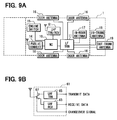
- a UHF transmitter/receiver unit 61 may be disposed in the in-vehicle device 1 as shown in FIG. 9A instead of the UHF receiver unit 12 and the UHF transmitter unit 41 .
- the UHF transmitter/receiver unit 61 is so configured as to internally include a UHF receiver unit 63 and a UHF transmitter unit 65 .
- a transmit/receive changeover switch 67 changes over whether the reception is to be conducted by the UHF receiver unit 63 , or the transmission is to be conducted by the UHF transmitter unit 65 .
- the UHF transmitter/receiver unit 61 is so configured as to change over the transmission or reception by the transmit/receive changeover switch 67 to conduct a half-duplex communication.
- This configuration can be replaced with another configuration when the transmission/reception can be implemented.
- the transmit/receive changeover switch 67 is replaced with a circulator, thereby conduct the transmission/reception by a full duplex communication.
- the above second embodiment shows an example in which the cell phone 34 transmits or receives the electronic mail with respect to the management server 33 .
- Data can be delivered in any data format in a communication between the in-vehicle device 1 and the management server 33 , or a communication between the cell phone 34 and the management server 33 . In this situation, any communication protocol can be used.
- the in-vehicle device 1 has an electronic mail transmitting function
- the electronic mail can be transmitted to the cell phone 34 via the mail server
- the above configuration can be applied.
- the fact that the mobile unit 2 has been found is described in the electronic mail.
- an address (URL) on Internet can be described in the electronic mail.
- the cell phone 34 accesses to the address, a web page that is distributed from the web server is displayed, and information indicative of the fact that the mobile unit 2 has been found out can be displayed in the web page.
- the above embodiments may further be modified to an electronic key system for door control of other objects, which may include a home and an office.
Landscapes
- Engineering & Computer Science (AREA)
- Mechanical Engineering (AREA)
- Lock And Its Accessories (AREA)
Applications Claiming Priority (2)
| Application Number | Priority Date | Filing Date | Title |
|---|---|---|---|
| JP2006-354096 | 2006-12-28 | ||
| JP2006354096A JP5003152B2 (ja) | 2006-12-28 | 2006-12-28 | 電子キーシステム |
Publications (2)
| Publication Number | Publication Date |
|---|---|
| US20080157919A1 US20080157919A1 (en) | 2008-07-03 |
| US8089342B2 true US8089342B2 (en) | 2012-01-03 |
Family
ID=39477875
Family Applications (1)
| Application Number | Title | Priority Date | Filing Date |
|---|---|---|---|
| US12/000,788 Expired - Fee Related US8089342B2 (en) | 2006-12-28 | 2007-12-17 | Electronic key system and method |
Country Status (5)
| Country | Link |
|---|---|
| US (1) | US8089342B2 (ko) |
| JP (1) | JP5003152B2 (ko) |
| KR (1) | KR100929134B1 (ko) |
| CN (1) | CN101211475B (ko) |
| DE (1) | DE102007062643B4 (ko) |
Cited By (9)
| Publication number | Priority date | Publication date | Assignee | Title |
|---|---|---|---|---|
| US20100050713A1 (en) * | 2008-09-02 | 2010-03-04 | Denso Corporation | Door lock control apparatus for vehicle |
| US20110201432A1 (en) * | 2008-08-15 | 2011-08-18 | Nxp B.V. | Container and electronic game system comprising such container |
| US8588995B2 (en) | 2011-04-01 | 2013-11-19 | Omron Automotive Electronics Co., Ltd. | Vehicle control device |
| US9569903B2 (en) | 2014-08-08 | 2017-02-14 | Toyota Jidosha Kabushiki Kaisha | Vehicle control apparatus |
| US9666005B2 (en) | 2014-02-14 | 2017-05-30 | Infinitekey, Inc. | System and method for communicating with a vehicle |
| US20170251335A1 (en) * | 2016-02-25 | 2017-08-31 | Omron Automotive Electronics Co., Ltd. | Vehicle control system |
| US9794753B1 (en) | 2016-04-15 | 2017-10-17 | Infinitekey, Inc. | System and method for establishing real-time location |
| US10356550B2 (en) | 2016-12-14 | 2019-07-16 | Denso Corporation | Method and system for establishing microlocation zones |
| US20230174016A1 (en) * | 2021-12-06 | 2023-06-08 | Hyundai Motor Company | Vehicle control system and method of controlling vehicle |
Families Citing this family (34)
| Publication number | Priority date | Publication date | Assignee | Title |
|---|---|---|---|---|
| US8188837B2 (en) * | 2008-08-08 | 2012-05-29 | General Motors Llc | Method of finding a key to a mobile vehicle |
| JP5596927B2 (ja) * | 2009-02-06 | 2014-09-24 | アルプス電気株式会社 | 車両用携帯機 |
| JP5402058B2 (ja) | 2009-02-16 | 2014-01-29 | 株式会社デンソー | 携帯機、携帯通信端末、および車両システム |
| JP5366731B2 (ja) * | 2009-09-17 | 2013-12-11 | オムロンオートモーティブエレクトロニクス株式会社 | 車両用制御装置、携帯機、携帯機探索システム |
| JP5249175B2 (ja) * | 2009-11-11 | 2013-07-31 | 株式会社東海理化電機製作所 | 電子キーシステムのキー位置判定装置 |
| CN102087760B (zh) * | 2009-12-04 | 2013-01-02 | 以勤科技股份有限公司 | 芯片认证干扰系统 |
| US20110140839A1 (en) * | 2009-12-11 | 2011-06-16 | Honda Motor Co., Ltd. | Method and system for disabling passive entry key located inside a vehicle |
| JP5045774B2 (ja) | 2010-03-12 | 2012-10-10 | 株式会社デンソー | 携帯機検知システム |
| FR2965434B1 (fr) * | 2010-09-28 | 2015-12-11 | Valeo Securite Habitacle | Procede d'appairage d'un telephone mobile avec un vehicule automobile et ensemble de verrouillage/deverrouillage |
| FR2974963B1 (fr) * | 2011-05-05 | 2014-01-10 | Valeo Securite Habitacle | Ensemble de communication par protocole determine |
| WO2013050409A1 (en) | 2011-10-07 | 2013-04-11 | Assa Abloy Czech & Slovakia S.R.O. | Solutions for relay attacks on passive keyless entry and go |
| CN102424031A (zh) * | 2011-11-18 | 2012-04-25 | 施舸 | 适用于装有rfid防盗系统的汽车远程遥控启动装置 |
| CN103569037B (zh) * | 2012-07-24 | 2017-05-24 | 浙江青年乘用车集团有限公司 | 感应式钥匙开关系统及控制方法 |
| JP6061085B2 (ja) | 2013-03-07 | 2017-01-18 | 株式会社デンソー | スマートエントリーシステム |
| CN103350678B (zh) * | 2013-07-25 | 2016-02-10 | 天津新日机电有限公司 | 一种电动车场控系统 |
| US9241249B2 (en) | 2013-07-29 | 2016-01-19 | GM Global Technology Operations LLC | Methods, systems and apparatus for providing notification at an automotive head unit that a wireless communication device is outside a vehicle |
| DE102013218920A1 (de) * | 2013-09-20 | 2015-03-26 | Ford Global Technologies, Llc | Verfahren zum Betrieb eines Kraftfahrzeugs in einem Betriebsmodus für Präsentationszwecke und Kraftfahrzeug |
| CN104021606A (zh) * | 2014-05-23 | 2014-09-03 | 无锡市崇安区科技创业服务中心 | 一种汽车遥控锁门状态确认方法 |
| CN105278397B (zh) * | 2014-07-24 | 2017-11-14 | 上海海拉电子有限公司 | 一种车辆远程控制系统及控制方法 |
| CN104477128B (zh) * | 2014-11-26 | 2017-07-21 | 东风汽车公司 | 一种防止汽车钥匙未拔时机械门锁误上锁的控制方法 |
| CN105225507A (zh) * | 2015-09-24 | 2016-01-06 | 上海车音网络科技有限公司 | 一种车辆监控方法及装置 |
| DE102016214687B4 (de) | 2016-08-08 | 2020-03-12 | Audi Ag | Verfahren zum Betreiben einer Diebstahlschutzvorrichtung, Diebstahlschutzvorrichtung für ein Kraftfahrzeug und Kraftfahrzeug |
| DE102016214848B4 (de) * | 2016-08-10 | 2023-02-23 | Audi Ag | Verfahren und System zum Erinnern eines Fahrzeuginsassen |
| DE102016217855B4 (de) * | 2016-09-19 | 2018-12-20 | Audi Ag | Verfahren zum Betreiben eines Überwachungssystems eines Kraftfahrzeugs sowie ein Überwachungssystem für ein Kraftfahrzeug |
| JP6743657B2 (ja) * | 2016-11-04 | 2020-08-19 | 横河電機株式会社 | 巡回点検システム、巡回点検装置、巡回点検方法、プログラム、および記録媒体 |
| CN106652124A (zh) * | 2016-11-08 | 2017-05-10 | 云蜂汽车有限公司 | 一种车门的控制方法及云服务平台 |
| CN106600913A (zh) * | 2016-11-15 | 2017-04-26 | 胡渐佳 | 基于状态变化的开门钥匙端监测识别系统 |
| JP6595551B2 (ja) * | 2017-09-20 | 2019-10-23 | 株式会社東海理化電機製作所 | カーシェアリングシステム |
| JP6958480B2 (ja) * | 2018-05-21 | 2021-11-02 | 株式会社デンソー | 車両用認証装置 |
| CN109131213B (zh) * | 2018-07-19 | 2021-12-07 | 奇瑞新能源汽车股份有限公司 | 一种汽车报警警示方法 |
| EP3647128B1 (en) * | 2018-11-02 | 2022-02-09 | Ningbo Geely Automobile Research & Development Co. Ltd. | A system and method for finding a key |
| US10919497B1 (en) * | 2019-10-09 | 2021-02-16 | Ford Global Technologies, Llc | Systems and methods for starting a vehicle using a secure password entry system |
| CN112744180B (zh) * | 2019-10-29 | 2023-04-28 | 现代自动车株式会社 | 用于连接的车辆控制的系统和方法 |
| KR102452832B1 (ko) * | 2019-12-13 | 2022-10-11 | 콘티넨탈 오토모티브 게엠베하 | 차량을 제어하는 전자 장치 및 그 동작 방법 |
Citations (26)
| Publication number | Priority date | Publication date | Assignee | Title |
|---|---|---|---|---|
| JPS6290486A (ja) | 1986-09-18 | 1987-04-24 | 日産自動車株式会社 | 車両用施錠制御装置 |
| DE19802532C1 (de) | 1998-01-26 | 1999-08-12 | Bosch Gmbh Robert | Verfahren zum Betreiben eines schlüssellosen Zutrittsystems eines Fahrzeugs |
| US5969597A (en) * | 1997-08-16 | 1999-10-19 | Robert Bosch Gmbh | Method for preventing misuse of transponders left inside a vehicle |
| US6087987A (en) * | 1997-09-02 | 2000-07-11 | Siemens Aktiengesellschaft | Method of locating an enabling component containing a transponder, and a motor vehicle with a corresponding locator |
| EP1041227A1 (fr) | 1999-04-02 | 2000-10-04 | Valeo Securite Habitacle | Systéme d'accès dit "mains libres" pour un véhicule automobile, équipé d'un dispositif avertisseur |
| DE19916308A1 (de) * | 1999-04-12 | 2000-10-19 | Bernd Keiderling | Schlüssel/Anhänger und/oder Freigabebauteil zur Bedienung eines Kraftfahrzeuges mit einer Anzeigevorrichtung, Parkautomat sowie Verfahren zu deren Gebrauch |
| US6166652A (en) * | 1997-06-23 | 2000-12-26 | Benvenuti; Kerrie | System and method for locating misplaced items |
| US6297737B1 (en) * | 2000-04-03 | 2001-10-02 | Ericsson Inc | Object locating system |
| EP1170711A1 (de) | 2000-07-05 | 2002-01-09 | Adam Opel Ag | Ortungsgerät für eine Kraftfahrzeugfernbedienung |
| US20020025823A1 (en) * | 2000-08-30 | 2002-02-28 | Omron Corporation | Radio system |
| US20030014164A1 (en) * | 2001-07-04 | 2003-01-16 | Shin Sung Woo | Apparatus and method for disabling a remote control unit of an automobile |
| US20030117295A1 (en) * | 2001-12-26 | 2003-06-26 | Toyota Jidosha Kabushiki Kaisha | Remote control system for on-vehicle equipment and remote control method for the same |
| US6624741B1 (en) * | 1998-08-28 | 2003-09-23 | Daimlerchrysler Ag | Vehicle locking system |
| US20040066298A1 (en) * | 2002-06-28 | 2004-04-08 | Agri-Tech Electronics Lc | Animal control apparatus with ultrasonic link |
| DE10317658A1 (de) | 2003-04-17 | 2004-11-18 | Robert Bosch Gmbh | Positionsanzeige und/oder Energieeinsparung bei Berechtigungssystemen |
| US20050046568A1 (en) * | 2003-09-01 | 2005-03-03 | Omron Corporation | Wireless terminal position detecting device and method |
| US20050073388A1 (en) * | 2003-10-01 | 2005-04-07 | Samsung Electronics Co., Ltd. | Mobile communication terminal for controlling a vehicle using a short message and method for controlling the same |
| JP2005220728A (ja) | 2004-01-09 | 2005-08-18 | Denso Corp | 携帯機探索装置 |
| JP2005232794A (ja) | 2004-02-19 | 2005-09-02 | Calsonic Kansei Corp | 車両用キーレス装置 |
| US6989741B2 (en) * | 2002-08-07 | 2006-01-24 | G-5 Electronics | Object tracking |
| US20060028339A1 (en) * | 2004-08-06 | 2006-02-09 | Denso Corporation | Portable device for electronic key system and portable device search system |
| US20060080007A1 (en) * | 2004-10-12 | 2006-04-13 | Gerard Christine M | Scheduling remote starting of vehicle |
| US20060082436A1 (en) * | 2004-09-07 | 2006-04-20 | Denso Corporation | Smart key system |
| US20060226976A1 (en) * | 2005-03-29 | 2006-10-12 | Hsu-Jung Wei | Device for helping find a remote control |
| US20070030165A1 (en) * | 2005-08-03 | 2007-02-08 | Denso Corporation | Portable unit locating system and method |
| US20070075849A1 (en) * | 2005-10-05 | 2007-04-05 | Pitt Lance D | Cellular augmented vehicle alarm notification together with location services for position of an alarming vehicle |
Family Cites Families (5)
| Publication number | Priority date | Publication date | Assignee | Title |
|---|---|---|---|---|
| US5485163A (en) * | 1994-03-30 | 1996-01-16 | Motorola, Inc. | Personal locator system |
| JP2002201838A (ja) * | 2000-12-28 | 2002-07-19 | Denso Corp | 車両用電子キー装置及び記録媒体 |
| JP2005076369A (ja) * | 2003-09-02 | 2005-03-24 | Honda Motor Co Ltd | 車両用遠隔ドアロック制御装置 |
| JP2005171666A (ja) * | 2003-12-12 | 2005-06-30 | Tokai Rika Co Ltd | 遠隔操作装置の携帯機及び遠隔操作装置の携帯機機能制限装置 |
| JP2006257767A (ja) * | 2005-03-17 | 2006-09-28 | Calsonic Kansei Corp | 車両用ドア開閉リモコン装置 |
-
2006
- 2006-12-28 JP JP2006354096A patent/JP5003152B2/ja not_active Expired - Fee Related
-
2007
- 2007-12-17 US US12/000,788 patent/US8089342B2/en not_active Expired - Fee Related
- 2007-12-24 DE DE200710062643 patent/DE102007062643B4/de not_active Expired - Fee Related
- 2007-12-27 KR KR20070138070A patent/KR100929134B1/ko active IP Right Grant
- 2007-12-28 CN CN2007101861807A patent/CN101211475B/zh not_active Expired - Fee Related
Patent Citations (27)
| Publication number | Priority date | Publication date | Assignee | Title |
|---|---|---|---|---|
| JPS6290486A (ja) | 1986-09-18 | 1987-04-24 | 日産自動車株式会社 | 車両用施錠制御装置 |
| US6166652A (en) * | 1997-06-23 | 2000-12-26 | Benvenuti; Kerrie | System and method for locating misplaced items |
| US5969597A (en) * | 1997-08-16 | 1999-10-19 | Robert Bosch Gmbh | Method for preventing misuse of transponders left inside a vehicle |
| US6087987A (en) * | 1997-09-02 | 2000-07-11 | Siemens Aktiengesellschaft | Method of locating an enabling component containing a transponder, and a motor vehicle with a corresponding locator |
| DE19802532C1 (de) | 1998-01-26 | 1999-08-12 | Bosch Gmbh Robert | Verfahren zum Betreiben eines schlüssellosen Zutrittsystems eines Fahrzeugs |
| US6624741B1 (en) * | 1998-08-28 | 2003-09-23 | Daimlerchrysler Ag | Vehicle locking system |
| JP2000326827A (ja) | 1999-04-02 | 2000-11-28 | Valeo Securite Habitacle | 警告装置を備えた、自動車用のいわゆるハンズフリーアクセスシステム |
| EP1041227A1 (fr) | 1999-04-02 | 2000-10-04 | Valeo Securite Habitacle | Systéme d'accès dit "mains libres" pour un véhicule automobile, équipé d'un dispositif avertisseur |
| DE19916308A1 (de) * | 1999-04-12 | 2000-10-19 | Bernd Keiderling | Schlüssel/Anhänger und/oder Freigabebauteil zur Bedienung eines Kraftfahrzeuges mit einer Anzeigevorrichtung, Parkautomat sowie Verfahren zu deren Gebrauch |
| US6297737B1 (en) * | 2000-04-03 | 2001-10-02 | Ericsson Inc | Object locating system |
| EP1170711A1 (de) | 2000-07-05 | 2002-01-09 | Adam Opel Ag | Ortungsgerät für eine Kraftfahrzeugfernbedienung |
| US20020025823A1 (en) * | 2000-08-30 | 2002-02-28 | Omron Corporation | Radio system |
| US20030014164A1 (en) * | 2001-07-04 | 2003-01-16 | Shin Sung Woo | Apparatus and method for disabling a remote control unit of an automobile |
| US20030117295A1 (en) * | 2001-12-26 | 2003-06-26 | Toyota Jidosha Kabushiki Kaisha | Remote control system for on-vehicle equipment and remote control method for the same |
| US20040066298A1 (en) * | 2002-06-28 | 2004-04-08 | Agri-Tech Electronics Lc | Animal control apparatus with ultrasonic link |
| US6989741B2 (en) * | 2002-08-07 | 2006-01-24 | G-5 Electronics | Object tracking |
| DE10317658A1 (de) | 2003-04-17 | 2004-11-18 | Robert Bosch Gmbh | Positionsanzeige und/oder Energieeinsparung bei Berechtigungssystemen |
| US20050046568A1 (en) * | 2003-09-01 | 2005-03-03 | Omron Corporation | Wireless terminal position detecting device and method |
| US20050073388A1 (en) * | 2003-10-01 | 2005-04-07 | Samsung Electronics Co., Ltd. | Mobile communication terminal for controlling a vehicle using a short message and method for controlling the same |
| JP2005220728A (ja) | 2004-01-09 | 2005-08-18 | Denso Corp | 携帯機探索装置 |
| JP2005232794A (ja) | 2004-02-19 | 2005-09-02 | Calsonic Kansei Corp | 車両用キーレス装置 |
| US20060028339A1 (en) * | 2004-08-06 | 2006-02-09 | Denso Corporation | Portable device for electronic key system and portable device search system |
| US20060082436A1 (en) * | 2004-09-07 | 2006-04-20 | Denso Corporation | Smart key system |
| US20060080007A1 (en) * | 2004-10-12 | 2006-04-13 | Gerard Christine M | Scheduling remote starting of vehicle |
| US20060226976A1 (en) * | 2005-03-29 | 2006-10-12 | Hsu-Jung Wei | Device for helping find a remote control |
| US20070030165A1 (en) * | 2005-08-03 | 2007-02-08 | Denso Corporation | Portable unit locating system and method |
| US20070075849A1 (en) * | 2005-10-05 | 2007-04-05 | Pitt Lance D | Cellular augmented vehicle alarm notification together with location services for position of an alarming vehicle |
Non-Patent Citations (6)
| Title |
|---|
| Anonymous, Adding a radio frequency-based locator feature to automotive key FOB, May 2002, Kenneth Mason Publications Ltd., Research disclosure# 457109. * |
| Chinese Office Action dated Dec. 18, 2009, issued in corresponding Chinese Application No. 200710186180.7, with English translation. |
| Chinese Office Action dated Jul. 31 2009, issued in corresponding Chinese Application No. 200710186180.7, with English translation. |
| German Office Action dated May 20, 2010, issued in corresponding German Application No. 10 2007 062 643.8-51, with English translation. |
| Korean Office Action dated May 18, 2009, issued in corresponding Korean Application No. 10-2007-0138070, with English translation. |
| U.S. Appl. No. 12/000,786, filed Dec. 17, 2007, Sugiura et al. |
Cited By (22)
| Publication number | Priority date | Publication date | Assignee | Title |
|---|---|---|---|---|
| US20110201432A1 (en) * | 2008-08-15 | 2011-08-18 | Nxp B.V. | Container and electronic game system comprising such container |
| US8608575B2 (en) * | 2008-08-15 | 2013-12-17 | Nxp B.V. | Container and electronic game system comprising such container |
| US20100050713A1 (en) * | 2008-09-02 | 2010-03-04 | Denso Corporation | Door lock control apparatus for vehicle |
| US8717142B2 (en) | 2008-09-02 | 2014-05-06 | Denso Corporation | Door lock control apparatus for vehicle |
| US8588995B2 (en) | 2011-04-01 | 2013-11-19 | Omron Automotive Electronics Co., Ltd. | Vehicle control device |
| US9666005B2 (en) | 2014-02-14 | 2017-05-30 | Infinitekey, Inc. | System and method for communicating with a vehicle |
| US11094151B2 (en) | 2014-02-14 | 2021-08-17 | Denso Corporation | System and method for communicating with a vehicle |
| US11972649B2 (en) * | 2014-02-14 | 2024-04-30 | Denso Corporation | System and method for communicating with a vehicle |
| US10410447B2 (en) | 2014-02-14 | 2019-09-10 | Denso Corporation | System and method for communicating with a vehicle |
| US20210366215A1 (en) * | 2014-02-14 | 2021-11-25 | Denso Corporation | System and method for communicating with a vehicle |
| US9569903B2 (en) | 2014-08-08 | 2017-02-14 | Toyota Jidosha Kabushiki Kaisha | Vehicle control apparatus |
| US20170251335A1 (en) * | 2016-02-25 | 2017-08-31 | Omron Automotive Electronics Co., Ltd. | Vehicle control system |
| US9867008B2 (en) * | 2016-02-25 | 2018-01-09 | Omron Automotive Electronics Co., Ltd. | Vehicle control system |
| US9794753B1 (en) | 2016-04-15 | 2017-10-17 | Infinitekey, Inc. | System and method for establishing real-time location |
| US11089433B2 (en) | 2016-04-15 | 2021-08-10 | Denso Corporation | System and method for establishing real-time location |
| US11979789B2 (en) | 2016-04-15 | 2024-05-07 | Denso Corporation | System and method for establishing real-time location |
| US10616710B2 (en) | 2016-04-15 | 2020-04-07 | Denso Corporation | System and method for establishing real-time location |
| US10356550B2 (en) | 2016-12-14 | 2019-07-16 | Denso Corporation | Method and system for establishing microlocation zones |
| US11889380B2 (en) | 2016-12-14 | 2024-01-30 | Denso Corporation | Method and system for establishing microlocation zones |
| US11265674B2 (en) | 2016-12-14 | 2022-03-01 | Denso Corporation | Method and system for establishing microlocation zones |
| US11153708B2 (en) | 2016-12-14 | 2021-10-19 | Denso Corporation | Method and system for establishing microlocation zones |
| US20230174016A1 (en) * | 2021-12-06 | 2023-06-08 | Hyundai Motor Company | Vehicle control system and method of controlling vehicle |
Also Published As
| Publication number | Publication date |
|---|---|
| KR20080063133A (ko) | 2008-07-03 |
| JP5003152B2 (ja) | 2012-08-15 |
| DE102007062643A1 (de) | 2008-07-10 |
| CN101211475A (zh) | 2008-07-02 |
| US20080157919A1 (en) | 2008-07-03 |
| DE102007062643B4 (de) | 2013-03-07 |
| JP2008163633A (ja) | 2008-07-17 |
| KR100929134B1 (ko) | 2009-12-01 |
| CN101211475B (zh) | 2012-05-23 |
Similar Documents
| Publication | Publication Date | Title |
|---|---|---|
| US8089342B2 (en) | Electronic key system and method | |
| US7388466B2 (en) | Integrated passive entry and remote keyless entry system | |
| US7224980B2 (en) | Radio system | |
| US20090096578A1 (en) | Smart entry system | |
| JP5508239B2 (ja) | 電子キーシステム | |
| WO2015174012A1 (ja) | 電子キーシステム | |
| JP5082729B2 (ja) | 無線装置、その制御方法、およびプログラム | |
| JP4035719B2 (ja) | 車両盗難防止システム及び方法 | |
| JP2005528016A (ja) | 対象に対するアクセス権若しくは対象の使用に対する権限の証明のための識別システム | |
| KR102225967B1 (ko) | 릴레이 공격의 방어 | |
| JP2011231567A (ja) | 電子キーシステム | |
| JP2010133099A (ja) | 無線装置、その制御方法、およびプログラム | |
| JP4213719B2 (ja) | 車載機器遠隔制御装置 | |
| JP2017115439A (ja) | 車載装置及び認証システム | |
| WO2005061289A1 (ja) | 盗難防止システム | |
| JP2012107377A (ja) | 車両用スマートキーの携帯機探索装置、及び携帯機探索方法 | |
| JP5436587B2 (ja) | 電子キー装置および電子キー装置に用いられる親機 | |
| JP3721145B2 (ja) | 車載機器遠隔制御システム | |
| JP5152011B2 (ja) | 電子キーシステム及び車両制御用携帯機 | |
| JP2009094767A (ja) | 無線装置、その制御方法、およびプログラム | |
| JP5406271B2 (ja) | 電子キー装置 | |
| JP2005320708A (ja) | 電子キーシステム、電子キー及び発信機 | |
| JP6347419B2 (ja) | 電子キーシステム | |
| JP6054647B2 (ja) | 施錠監視システムおよび施錠監視方法 | |
| WO2021124766A1 (ja) | 電子キーシステム |
Legal Events
| Date | Code | Title | Description |
|---|---|---|---|
| AS | Assignment |
Owner name: DENSO CORPORATION, JAPAN Free format text: ASSIGNMENT OF ASSIGNORS INTEREST;ASSIGNORS:SUGIURA, MASAHIRO;NAITOH, HIROMICHI;MATSUMOTO, MUNENORI;AND OTHERS;REEL/FRAME:020412/0899;SIGNING DATES FROM 20071218 TO 20071224 Owner name: DENSO CORPORATION, JAPAN Free format text: ASSIGNMENT OF ASSIGNORS INTEREST;ASSIGNORS:SUGIURA, MASAHIRO;NAITOH, HIROMICHI;MATSUMOTO, MUNENORI;AND OTHERS;SIGNING DATES FROM 20071218 TO 20071224;REEL/FRAME:020412/0899 |
|
| FEPP | Fee payment procedure |
Free format text: PAYOR NUMBER ASSIGNED (ORIGINAL EVENT CODE: ASPN); ENTITY STATUS OF PATENT OWNER: LARGE ENTITY |
|
| STCF | Information on status: patent grant |
Free format text: PATENTED CASE |
|
| FEPP | Fee payment procedure |
Free format text: PAYOR NUMBER ASSIGNED (ORIGINAL EVENT CODE: ASPN); ENTITY STATUS OF PATENT OWNER: LARGE ENTITY |
|
| FPAY | Fee payment |
Year of fee payment: 4 |
|
| FEPP | Fee payment procedure |
Free format text: MAINTENANCE FEE REMINDER MAILED (ORIGINAL EVENT CODE: REM.); ENTITY STATUS OF PATENT OWNER: LARGE ENTITY |
|
| LAPS | Lapse for failure to pay maintenance fees |
Free format text: PATENT EXPIRED FOR FAILURE TO PAY MAINTENANCE FEES (ORIGINAL EVENT CODE: EXP.); ENTITY STATUS OF PATENT OWNER: LARGE ENTITY |
|
| STCH | Information on status: patent discontinuation |
Free format text: PATENT EXPIRED DUE TO NONPAYMENT OF MAINTENANCE FEES UNDER 37 CFR 1.362 |
|
| FP | Lapsed due to failure to pay maintenance fee |
Effective date: 20200103 |