US7605502B2 - Automotive alternator with rectifier having high-strength heat sinks - Google Patents
Automotive alternator with rectifier having high-strength heat sinks Download PDFInfo
- Publication number
- US7605502B2 US7605502B2 US11/509,673 US50967306A US7605502B2 US 7605502 B2 US7605502 B2 US 7605502B2 US 50967306 A US50967306 A US 50967306A US 7605502 B2 US7605502 B2 US 7605502B2
- Authority
- US
- United States
- Prior art keywords
- heat sink
- major surface
- negative
- ribs
- positive
- Prior art date
- Legal status (The legal status is an assumption and is not a legal conclusion. Google has not performed a legal analysis and makes no representation as to the accuracy of the status listed.)
- Active, expires
Links
Images


Classifications
-
- H—ELECTRICITY
- H02—GENERATION; CONVERSION OR DISTRIBUTION OF ELECTRIC POWER
- H02K—DYNAMO-ELECTRIC MACHINES
- H02K9/00—Arrangements for cooling or ventilating
- H02K9/22—Arrangements for cooling or ventilating by solid heat conducting material embedded in, or arranged in contact with, the stator or rotor, e.g. heat bridges
-
- H—ELECTRICITY
- H01—ELECTRIC ELEMENTS
- H01L—SEMICONDUCTOR DEVICES NOT COVERED BY CLASS H10
- H01L25/00—Assemblies consisting of a plurality of individual semiconductor or other solid state devices ; Multistep manufacturing processes thereof
- H01L25/03—Assemblies consisting of a plurality of individual semiconductor or other solid state devices ; Multistep manufacturing processes thereof all the devices being of a type provided for in the same subgroup of groups H01L27/00 - H01L33/00, or in a single subclass of H10K, H10N, e.g. assemblies of rectifier diodes
- H01L25/10—Assemblies consisting of a plurality of individual semiconductor or other solid state devices ; Multistep manufacturing processes thereof all the devices being of a type provided for in the same subgroup of groups H01L27/00 - H01L33/00, or in a single subclass of H10K, H10N, e.g. assemblies of rectifier diodes the devices having separate containers
- H01L25/11—Assemblies consisting of a plurality of individual semiconductor or other solid state devices ; Multistep manufacturing processes thereof all the devices being of a type provided for in the same subgroup of groups H01L27/00 - H01L33/00, or in a single subclass of H10K, H10N, e.g. assemblies of rectifier diodes the devices having separate containers the devices being of a type provided for in group H01L29/00
- H01L25/115—Assemblies consisting of a plurality of individual semiconductor or other solid state devices ; Multistep manufacturing processes thereof all the devices being of a type provided for in the same subgroup of groups H01L27/00 - H01L33/00, or in a single subclass of H10K, H10N, e.g. assemblies of rectifier diodes the devices having separate containers the devices being of a type provided for in group H01L29/00 the devices being arranged next to each other
-
- H—ELECTRICITY
- H02—GENERATION; CONVERSION OR DISTRIBUTION OF ELECTRIC POWER
- H02K—DYNAMO-ELECTRIC MACHINES
- H02K11/00—Structural association of dynamo-electric machines with electric components or with devices for shielding, monitoring or protection
- H02K11/04—Structural association of dynamo-electric machines with electric components or with devices for shielding, monitoring or protection for rectification
- H02K11/049—Rectifiers associated with stationary parts, e.g. stator cores
- H02K11/05—Rectifiers associated with casings, enclosures or brackets
-
- H—ELECTRICITY
- H02—GENERATION; CONVERSION OR DISTRIBUTION OF ELECTRIC POWER
- H02K—DYNAMO-ELECTRIC MACHINES
- H02K19/00—Synchronous motors or generators
- H02K19/16—Synchronous generators
- H02K19/36—Structural association of synchronous generators with auxiliary electric devices influencing the characteristic of the generator or controlling the generator, e.g. with impedances or switches
- H02K19/365—Structural association of synchronous generators with auxiliary electric devices influencing the characteristic of the generator or controlling the generator, e.g. with impedances or switches with a voltage regulator
-
- H—ELECTRICITY
- H02—GENERATION; CONVERSION OR DISTRIBUTION OF ELECTRIC POWER
- H02K—DYNAMO-ELECTRIC MACHINES
- H02K9/00—Arrangements for cooling or ventilating
- H02K9/22—Arrangements for cooling or ventilating by solid heat conducting material embedded in, or arranged in contact with, the stator or rotor, e.g. heat bridges
- H02K9/227—Heat sinks
-
- H—ELECTRICITY
- H01—ELECTRIC ELEMENTS
- H01L—SEMICONDUCTOR DEVICES NOT COVERED BY CLASS H10
- H01L23/00—Details of semiconductor or other solid state devices
- H01L23/34—Arrangements for cooling, heating, ventilating or temperature compensation ; Temperature sensing arrangements
- H01L23/36—Selection of materials, or shaping, to facilitate cooling or heating, e.g. heatsinks
- H01L23/367—Cooling facilitated by shape of device
-
- H—ELECTRICITY
- H01—ELECTRIC ELEMENTS
- H01L—SEMICONDUCTOR DEVICES NOT COVERED BY CLASS H10
- H01L2924/00—Indexing scheme for arrangements or methods for connecting or disconnecting semiconductor or solid-state bodies as covered by H01L24/00
- H01L2924/0001—Technical content checked by a classifier
- H01L2924/0002—Not covered by any one of groups H01L24/00, H01L24/00 and H01L2224/00
Definitions
- the present invention relates generally to automotive alternators and rectifiers. More particularly, the invention relates to an automotive alternator which includes a rectifier having high-strength heat sinks.
- a rectifier that includes a plurality of rectifying elements generally experiences a great rise in temperature during operation of the automotive alternator. Accordingly, it is required to secure sufficient cooling of the rectifier without increasing the size and cost of the automotive alternator.
- U.S. Pat. No. 6,809,443 discloses a rectifying device incorporated in an automotive alternator.
- rectifying elements are press-fitted in receiving holes formed in a pair of cooling fins (i.e., heat sinks), thereby eliminating conventional soldering operation; the cooling fins each have a plurality of ribs extending radially with respect to a rotary shaft of the automotive alternator, thereby improving the cooling performance of the cooling fins without increasing the size of the automotive alternator.
- US Patent Application Publication No. 2004/0256924 discloses a rectifier incorporated in an automotive alternator.
- rectifying elements are press-fitted in press-in holes formed in a pair of radiating fins (i.e., heat sinks); the radiating fins each have a plurality of radial sub-fins that extends radially with respect to a rotary shaft of the automotive alternator; the radiating fins each further have a plurality of arc-like sub-fins, each of which is formed in the vicinity of one of the press-in holes, thereby enhancing the strength thereof; the radiating fins each have a large thickness in the vicinities of the press-in holes, so as to prevent cracks from occurring during the operation of press-fitting the rectifying elements into the press-in holes.
- the cooling or radiating fins have formed therein the receiving or press-in holes and the ribs or sub-fins, they have a very complicated shape.
- thickness-reducing portions and stress-concentrating portions may exist in the cooling or radiating fins; those portions may disenable the cooling or radiating fins from withstanding stress caused by the operation of press-fitting the rectifying elements into the receiving or press-in holes and thus may cause the cooling or radiating fins to crack.
- cooling or radiating fins it is desirable to manufacture those by aluminum die casting.
- the present invention has been made in view of the above-mentioned problems.
- a rectifier for an automotive alternator which includes: a plurality of rectifying elements configured to rectify an AC power generated by a stator of the automotive alternator to a DC power; and a heat sink having a plurality of fitting holes, in each of which one of the rectifying elements is fitted, and a major surface on which the fitting holes open, the heat sink also having a plurality of substantially annular ribs, each of which is formed on the major surface of the heat sink around a corresponding one of the fitting holes, each of the ribs having a first portion, which lies in an area on the major surface where a minimum distance between an inner edge of the heat sink defining the corresponding fitting hole and an outer edge of the heat sink defining an outline of the heat sink is smaller, and a second portion that lies in an area on the major surface where a minimum distance between the inner and outer edges is larger, the first portion having a greater protruding height from the major surface of the heat sink than the second portion.
- the rectifying elements are positive-side rectifying elements and the heat sink is a positive-side heat sink; the rectifier further includes a negative-side heat sink, which has the same structure as the positive-side heat sink, and a plurality of negative-side rectifying elements each of which is fitted in one of a plurality of fitting holes of the negative-side heat sink.
- the positive-side and negative-side heat sinks are disposed such that the major surfaces of the positive-side and negative-side heat sinks are parallel to each other.
- the rectifier further includes a terminal block which is interposed between the positive-side and negative-side heat sinks and includes therein electrical conductors for making electrical connection among the positive-side rectifying elements, the negative-side rectifying elements, and the stator.
- the second portion of at least one of the ribs on the major surface of the heat sink has the protruding height from the major surface being equal to zero.
- Each of the ribs on the major surface of the heat sink further has a connecting portion between the first and second portions, which has a surface inclined to axial end surfaces of the first and second portions; interfaces between the surface of the connecting portion and the axial end surface of the first portion and between the surface of the connecting portion and the axial end surface of the second portion are rounded.
- an automotive alternator which includes: a rotor having a rotary shaft and working to create a rotating magnetic field; a stator working to generate an AC power in the rotating magnetic field created by the rotor; a frame supporting the rotor and the stator; and a rectifier including a plurality of rectifying elements and a heat sink, the rectifying elements being electrically connected to the stator to rectify the AC power generated by the stator to a DC power, the heat sink having a plurality of fitting holes, in each of which one of the rectifying elements is fitted, and a major surface on which the fitting holes open, the heat sink also having a plurality of substantially annular ribs, each of which is formed on the major surface of the heat sink around a corresponding one of the fitting holes, each of the ribs having a first portion, which lies in an area on the major surface where a minimum distance between an inner edge of the heat sink defining the corresponding fitting hole and an outer edge of the heat sink defining an outline
- the heat sink has formed therein at least one through-hole which opens on the major surface of the heat sink in a position closer to the second portion than the first portion of the closet one of the ribs to the through-hole.
- the automotive alternator further includes a cooling fan which is configured to rotate with rotation of the rotor to create a cooling air flow that passes through the at lease one through-hole of the heat sink.
- the heat sink further has a plurality of fins each of which extends in a direction perpendicular to a normal direction of the major surface of the heat sink.
- the fins are integrally formed with at least one of the first portions of the ribs of the heat sink.
- the fins may be so formed as to protrude from the at least one of the first portions of the ribs in the normal direction of the major surface of the heat sink. Otherwise, the fins may be so formed as to protrude from the at least one of the first portions of the ribs in the direction perpendicular to the normal direction of the major surface of the heat sink.
- FIG. 1 is a partially cross-sectional view showing the overall configuration of an automotive alternator according to the first embodiment of the invention
- FIG. 2 is a plan view showing the overall configuration of a rectifier according to the first embodiment of the invention
- FIG. 3 is an enlarged partially cross-sectional view showing part of the automotive alternator including the rectifier according to the first embodiment of the invention
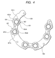
- FIG. 4 is a plan view showing a negative-side heat sink of the rectifier according to the first embodiment of the invention.
- FIG. 5 is a plan view showing part of a negative-side heat sink of a rectifier according to the second embodiment of the invention.
- FIG. 6 is a cross-sectional view taken along the line VI-VI in FIG. 5 ;
- FIG. 7 is a plan view showing part of a negative-side heat sink of a rectifier according to the third embodiment of the invention.
- FIG. 8 is a plan view showing the overall configuration of a rectifier according to the fourth embodiment of the invention.
- FIG. 9 is a perspective view showing part of a positive-side heat sink of the rectifier according to the fourth embodiment of the invention.
- FIG. 10 is a perspective view showing part of a negative-side heat sink of the rectifier according to the fourth embodiment of the invention.
- FIG. 11 is a perspective view showing the part of the negative-side heat sink of the rectifier according to the fourth embodiment of the invention in the opposite direction to FIG. 10 .
- FIG. 1 shows the overall configuration of an automotive alternator 1 according to the first embodiment of the invention.
- the automotive alternator 1 includes a rotor 2 , a stator 4 , a frame 3 , a rectifier 5 , brushes 7 , a voltage regulator 9 , a connector case 6 , a protecting cover 8 , and a pulley 10 .
- the rotor 2 includes a rotary shaft 21 , a field winding 22 , a pole core 24 , and a cooling fan 26 .
- the field winding 22 is so wound around the pole core 24 that when a filed current (or exciting current) is supplied to the field winding 22 , the pole core 24 forms magnetic poles, in other words, a rotating magnetic field is created by the rotor 2 .
- the cooling fan 26 is mounted to the rectifier-side (i.e., the right-side in FIG. 1 ) axial end of the pole core 24 ; it works to create a cooling air flow that passes through the rectifier 5 .
- the stator 4 is so configured as to surround the rotor 2 .
- the stator 4 includes a three-phase stator winding 41 and a stator core 42 .
- the stator winding 41 is so wound around the stator core 42 that the rotating magnetic field created by the rotor 2 passes through the stator core 42 , thus inducing three-phase alternating current in the stator winding 41 .
- the frame 3 is composed of a front frame 3 a and a rear frame 3 b .
- the frame 3 supports the rotary shaft 21 of the rotor 2 via bearings 3 c and 3 d , which are respectively provided in the front and rear frames 3 a and 3 d .
- the frame 3 also supports the stator core 42 of the stator 4 by means of a plurality fixing bolts 3 e.
- the rectifier 5 is configured to full-wave rectify the three-phase AC power outputted from the stator winding 41 of the stator 4 to obtain a DC power. Details of the rectifier 5 will be described later.
- the brushes 7 are in sliding contacts with slip rings 27 mounted on the rotary shaft 21 , so that the filed current can be supplied from the brushes 7 to the field winding 22 via the slip rings 27 .
- the voltage regulator 9 is configured to regulate the DC voltage outputted from the rectifier 5 through manipulation of the field current supplied to the filed winding 22 .
- the connector case 6 holds therein terminals for inputting and outputting electric signals from and to a vehicle control device (not shown).
- the protecting cover 8 which is made of a resin material, is so fixed to the rear frame 3 b that it covers the rectifier 5 , the voltage regulator 9 , and the brushes 7 , thereby protecting them from foreign matters.
- the pulley 10 is mounted on the rotary shaft 21 to transmit a driving force from an engine to the automotive alternator 1 via a belt (not shown).
- the rectifier 5 includes a positive-side heat sink 501 , a plurality of positive-side diodes 502 mounted to the positive-side heat sink 501 , a negative-side heat sink 503 , a plurality of negative-side diodes 504 mounted to the negative-side heat sink 503 , and a terminal block 513 interposed between the positive-side and negative-side heat sinks 501 and 503 .
- the positive-side and negative-side heat sinks 501 and 503 are apart from each other in the axial direction of the rotor 2 (i.e., the axial direction of the rotary shaft 21 ) and disposed around the rotary shaft 21 such that they overlap each other in the axial direction of the rotor 2 .
- the terminal block 513 is made of a resin material and electrically insulates the positive-side and negative-side heat sinks 501 and 503 from each other.
- the terminal block 513 has electrical conductors 514 insert-molded therein.
- the electrical conductors 514 electrically connect the three-phase stator winding 41 of the stator 4 to the positive-side diodes 502 and the negative-side diodes 504 .
- the positive-side diodes 502 and the negative-side diodes 504 work, as rectifying elements, to full-wave rectify the three-phase AC power outputted from the stator winding 41 .
- Each of the positive-side diodes 502 is press-fitted in one of a plurality of fitting holes 502 A formed in the positive-side heat sink 501 and has a lead 510 extending therefrom toward the negative-side heat sink 503 .
- each of the negative-side diodes 504 is press-fitted in one of a plurality of fitting holes 504 A formed in the negative-side heat sink 503 and has a lead 512 extending therefrom toward the positive-side heat sink 501 .
- the leads 510 extending from the positive-side diodes 502 and the leads 512 extending from the negative-side diodes 504 are connected to the electrical conductors 514 in the terminal block 513 , thereby forming at least one set of three-phase full-wave rectification circuit.
- a total of six positive-side diodes 502 and a total of six negative-side diodes 504 are employed, as seen from FIG. 2 , to form two sets of three-phase full-wave rectification circuit.
- the DC power obtained by the full-wave rectification is taken out from a blot 500 that is attached to the positive-side heat sink 501 to serve as an output terminal of the rectifier 5 .
- the rectifier 5 having the above-described structure is interposed between the rear frame 3 b and the protecting cover 8 and fixed therebetween by means of a plurality of fixing bolts 31 .
- the fixing bolts 31 also serve as supporting members for supporting a rear bearing box 30 .
- the negative-side heat sink 503 has a greater outer diameter than the positive-side heat sink 504 , and the negative-side diodes 504 are accordingly located radially outside of the positive-side diodes 502 .
- the negative-side heat sink 503 abuts the rear frame 3 b in the vicinities of the fixing bolts 31 .
- both the positive-side and negative-side heat sinks 501 and 503 are made by aluminum die casting, so as to reduce the manufacturing cost thereof through improvement in volume efficiency.
- the negative-side heat sink 503 has a plurality of annular ribs 601 formed on a major surface 553 thereof that faces the protecting cover 8 .
- each of the ribs 601 is formed around a corresponding one of the fitting holes 504 A that open on the major surface 553 .
- Each of the ribs 601 includes a plurality of portions having different protruding heights from the major surface 553 ; the protruding heights of the portions are in inverse proportion to the radial thicknesses of the negative-side heat sink 503 in the respective areas where the portions lie.
- the radial thickness of the negative-side heat sink 503 in an area on the major surface 553 is defined by the minimum distance between an inner edge 563 of the negative-side heat sink 503 defining the corresponding fitting hole 504 A and an outer edge 564 of the negative-side heat sink 503 defining the outline of the negative-side heat sink 503 in that area on the major surface 553 .
- each of the ribs 601 has a first portion 601 a and a second portion 601 b .
- the first portion 601 a lies in an area on the major surface 553 where the radial thickness of the negative-side heat sink 503 is smaller, while the second portion 601 b lies in an area on the major surface 553 where the radial thickness of the negative-side heat sink 503 is larger. Accordingly, the first portion 601 a has a greater protruding height from the major surface 553 than the second portion 601 b.
- the protruding heights of the portions of each of the ribs 601 are set such that the geometrical moment of inertia I of the negative-side heat sink 503 is uniform along the circumferential direction of the corresponding fitting hole 504 A.
- the positive-side heat sink 501 has a plurality of annular ribs 602 formed on a major surface 551 thereof that faces the protecting cover 8 .
- each of the ribs 602 is formed around a corresponding one of the fitting holes 502 A that open on the major surface 551 .
- Each of the ribs 602 includes a plurality of portions having different protruding heights from the major surface 551 ; the protruding heights of the portions are in inverse proportion to the radial thicknesses of the positive-side heat sink 501 in the respective areas where the portions lie.
- each of the ribs 602 has a first portion 602 a and a second portion 602 b .
- the first portion 602 a lies in an area on the major surface 551 where the radial thickness of the positive-side heat sink 501 is smaller, while the second portion 602 b lies in an area on the major surface 551 where the radial thickness of the positive-side heat sink 501 is larger. Accordingly, the first portion 602 a has a greater protruding height from the major surface 551 than the second portion 602 b.
- the protruding heights of the portions of each of the ribs 602 are set such that the geometrical moment of inertia I of the positive-side heat sink 501 is uniform along the circumferential direction of the corresponding fitting hole 502 A.
- the total surface areas of the negative-side and positive-side heat sinks 503 and 501 are increased, thereby enhancing the cooling capability of the heat sinks 503 and 501 .
- FIG. 5 shows part of a negative-side heat sink 503 of a rectifier 5 according to the second embodiment of the invention.
- each of ribs 601 formed on a major surface 553 of the negative-side heat sink 503 has a first portion 601 a and a second portion 601 c .
- the first portion 601 a lies in an area on the major surface 553 where the radial thickness of the negative-side heat sink 503 is smaller, while the second portion 601 c lies in an area on the major surface 553 where the radial thickness of the negative-side heat sink 503 is larger.
- the first portion 601 a has a large protruding height from the major surface 553
- the second portion 601 c has a protruding height from the major surface 553 being equal to zero.
- each of the ribs 601 has the shape of an incomplete ring.
- each of the ribs 601 has a connecting portion 601 e between the first and second portions 601 a and 601 c .
- the connecting portion 601 e has a surface that is inclined to axial end surfaces of the first and second portions 601 a and 601 c .
- interfaces 601 f between the surface of the connecting portion 601 e and the axial end surface of the first portion 601 a and between the surface of the connecting portion 601 e and the axial end surface of the second portion 601 c are rounded.
- a positive-side heat sink 501 of the rectifier 5 also has a plurality of ribs 602 that are formed in the same manner as the ribs 601 of the negative-side heat sink 503 described above.
- the formation of the ribs 601 and 602 according to the second embodiment is particularly useful in cases where it is impossible for the ribs 601 or 602 to have large protruding heights in areas where the radial thickness of the negative-side heat sink 503 or the positive-side heat sink 501 is small, due to dimensional constraints. More specifically, in such cases, it is still possible to secure sufficiently high strength of the negative-side heat sink 503 or the positive-side heat sink 501 by setting the protruding heights of the ribs 601 or 602 to zero instead in areas where the radial thickness of the negative-side heat sink 503 or the positive-side heat sink 501 is large.
- FIG. 7 shows part of a negative-side heat sink 503 of a rectifier 5 according to the third embodiment of the invention.
- each of the ribs 601 has, as in the second embodiment, both a first portion 601 a whose protruding height is large and a second portion 601 c whose protruding height is zero.
- the negative-side heat sink 503 further has a plurality of through-holes 603 , each of which is formed in the vicinity of the second portion 601 c of a corresponding one of the ribs 601 and has the shape of a curved band.
- a positive-side heat sink 501 of the rectifier 5 also has a plurality of through-holes 603 that are formed in the same manner as those of the negative-side heat sink 503 described above.
- the total surface areas of the negative-side and positive-side heat sinks 503 and 501 are further increased, thereby enhancing the cooling capability of the heat sinks 503 and 501 .
- the cooling air flow created by the cooling fan 26 will pass through the through-holes 603 , thus further improving the cooling performance of the negative-side and positive-side heat sinks 503 and 501 .
- FIG. 8 shows a rectifier 5 according to the fourth embodiment of the invention.
- FIG. 9 shows part of a positive-side heat sink 501 of the rectifier 5 according to the fourth embodiment.
- FIG. 10 shows part of a negative-side heat sink 503 of the rectifier 5 according to the fourth embodiment.
- FIG. 11 shows the part of the negative-side heat 503 in the opposite direction to FIG. 10 .
- the positive-side heat sink 501 has a plurality of fins 605 formed in the vicinity of each of the fitting holes 502 A.
- each of the fins 605 extends in the radial direction of the rotor 2 (i.e., in a direction perpendicular to the normal direction of a major surface 551 of the heat sink 501 ). Further, each of the fins 605 is integrally formed with one of large-protruding-height portions 602 a of a corresponding rib 602 on the major surface 551 , so as to protrude from the large-protruding-height portion 602 in the axial direction of the rotor 2 (i.e., in the normal direction of the major surface 551 ).
- the negative-side heat sink 503 has a plurality of fins 606 formed in the vicinity of each of the fitting holes 504 A.
- each of the fins 606 extends in the radial direction of the rotor 2 (i.e., in a direction perpendicular to the normal direction of a major surface 553 of the heat sink 503 ). Further, part of the fins 606 are integrally formed with one of large-protruding-height portions 601 a of a corresponding rib 601 on the major surface 553 , so as to protrude from the large-protruding-height portion 601 a in the radial direction of the rotor 2 .
- the negative-side heat sink 503 further has a plurality of ribs 601 formed on a major surface 573 thereof which is opposite to the major surface 553 and thus faces the rear frame 3 b . Further, part of the fins 606 are integrally formed with one of large-protruding-height portions 601 a of the ribs 601 on the major surface 573 , so as to protrude from the large-protruding-height portion 601 a in the axial direction of the rotor 2 (i.e., in the normal direction of the major surface 573 ).
- the total surface areas of the negative-side and positive-side heat sinks 503 and 501 are further increased, thereby further enhancing the cooling capability of the heat sinks 503 and 501 .
- the fins 606 and 605 are integrally formed with the large-protruding-height portions 601 a of the ribs 601 or the large-protruding-height portions 602 a of the ribs 602 , it is possible to secure sufficiently high strength of the fins 606 and 605 even with the complicated shapes of the fins 606 and 605 .
- the third embodiment of the invention there is provided only one through-hole 603 with the curved-band shape in the vicinity of each of the second portions 601 c of the ribs 601 on the negative-side heat sink 503 and the second portions 602 c of the ribs 602 on the positive-side heat sink 501 .
- both the positive-side and negative-side heat sinks 501 and 503 are made by aluminum die casting.
- the heat sinks 501 and 503 may also be made by machining metal materials having high heat conductivity, such as aluminum and copper.
- the ribs 601 on the negative-side heat sink 503 and the ribs 602 on the positive-side heat sink 501 are provided.
- all of the fitting holes 504 A and 502 A are each provided with one of the ribs 601 or one of the ribs 602 formed in the vicinity thereof.
Applications Claiming Priority (2)
| Application Number | Priority Date | Filing Date | Title |
|---|---|---|---|
| JP2005-247677 | 2005-08-29 | ||
| JP2005247677A JP4497062B2 (ja) | 2005-08-29 | 2005-08-29 | 車両用交流発電機 |
Publications (2)
| Publication Number | Publication Date |
|---|---|
| US20070046114A1 US20070046114A1 (en) | 2007-03-01 |
| US7605502B2 true US7605502B2 (en) | 2009-10-20 |
Family
ID=36975362
Family Applications (1)
| Application Number | Title | Priority Date | Filing Date |
|---|---|---|---|
| US11/509,673 Active 2028-01-16 US7605502B2 (en) | 2005-08-29 | 2006-08-25 | Automotive alternator with rectifier having high-strength heat sinks |
Country Status (5)
| Country | Link |
|---|---|
| US (1) | US7605502B2 (ja) |
| EP (1) | EP1760863B1 (ja) |
| JP (1) | JP4497062B2 (ja) |
| KR (1) | KR100820283B1 (ja) |
| DE (1) | DE602006012253D1 (ja) |
Cited By (4)
| Publication number | Priority date | Publication date | Assignee | Title |
|---|---|---|---|---|
| US20100007231A1 (en) * | 2008-07-09 | 2010-01-14 | Mitsubishi Electric Corporation | Alternator |
| US9312742B2 (en) | 2013-03-01 | 2016-04-12 | Hamilton Sundstrand Corporation | Connector and spring assembly for a generator |
| US20180269750A1 (en) * | 2015-11-10 | 2018-09-20 | Mitsubishi Electric Corporation | Ac power generator |
| US11051433B2 (en) * | 2018-01-11 | 2021-06-29 | Denso Corporation | Rectifier of rotating electric machine |
Families Citing this family (13)
| Publication number | Priority date | Publication date | Assignee | Title |
|---|---|---|---|---|
| US7531925B2 (en) * | 2007-04-24 | 2009-05-12 | Remy International, Inc. | High current capacity rectifier package |
| JP4931739B2 (ja) * | 2007-08-31 | 2012-05-16 | 日立オートモティブシステムズ株式会社 | 車両用交流発電機 |
| JP4506820B2 (ja) | 2007-11-22 | 2010-07-21 | 株式会社デンソー | 車両用交流発電機の整流装置 |
| DE102008002638A1 (de) * | 2008-06-25 | 2009-12-31 | Robert Bosch Gmbh | Elektrische Maschine |
| DE102008042504A1 (de) * | 2008-09-30 | 2010-10-21 | Robert Bosch Gmbh | Elektrische Maschine mit einem Kontaktelement zur elektrischen Verbindung elektrischer Bauteile |
| JP5523495B2 (ja) * | 2011-04-22 | 2014-06-18 | 三菱電機株式会社 | フィンチューブ型熱交換器及び冷凍サイクル装置 |
| JP5418861B2 (ja) * | 2011-06-23 | 2014-02-19 | 株式会社デンソー | 車両用交流発電機 |
| JP2014001869A (ja) * | 2012-06-15 | 2014-01-09 | Mitsubishi Electric Corp | 熱交換器及び冷凍サイクル装置 |
| US9380717B2 (en) * | 2012-07-27 | 2016-06-28 | Illinois Tool Works Inc. | Rectifier module for power conversion circuits |
| EP3211768B1 (en) * | 2014-10-21 | 2021-04-14 | Mitsubishi Electric Corporation | Rotating electrical machine for vehicle |
| MX367320B (es) * | 2015-04-28 | 2019-08-15 | Mitsubishi Electric Corp | Máquina eléctrica rotatoria. |
| EP3334014B1 (en) * | 2015-08-06 | 2019-07-31 | Mitsubishi Electric Corporation | Rotating electrical machine for vehicle |
| JP6688458B2 (ja) * | 2016-03-22 | 2020-04-28 | 株式会社デンソー | 回転電機 |
Citations (17)
| Publication number | Priority date | Publication date | Assignee | Title |
|---|---|---|---|---|
| FR1330419A (fr) | 1962-08-01 | 1963-06-21 | Gen Motors Corp | Machine dynamoélectrique |
| JPS59198862A (ja) | 1983-04-21 | 1984-11-10 | Nippon Denso Co Ltd | 車両用交流発電機の冷却フイン構造 |
| JPH1056762A (ja) | 1996-08-09 | 1998-02-24 | Denso Corp | 車両用交流発電機 |
| JPH1056760A (ja) | 1996-08-09 | 1998-02-24 | Denso Corp | 車両用交流発電機 |
| GB2334815A (en) | 1998-02-26 | 1999-09-01 | Mitsubishi Electric Corp | Compact rectifier used in automobile AC generator |
| DE19828518A1 (de) | 1998-06-26 | 1999-12-30 | Bosch Gmbh Robert | Elektrische Maschine, vorzugsweise Drehstromgenerator mit Gleichrichter-Baueinheit |
| US6184602B1 (en) | 1997-09-25 | 2001-02-06 | Denso Corporation | Rectifying apparatus for an automotive AC generator |
| US20030178899A1 (en) | 2001-07-16 | 2003-09-25 | Michael Aeschlimann | Current rectifier assembly for rotating electrical machines, in particular motor vehicle alternator |
| US6707691B2 (en) | 2002-04-17 | 2004-03-16 | Delphi Technologies, Inc. | Compact rectifier bridge and method for manufacturing the same |
| US20040051409A1 (en) | 2002-09-13 | 2004-03-18 | Denso Corporation | Alternator for an automotive vehicle |
| US20040174081A1 (en) | 2003-03-06 | 2004-09-09 | Visteon Global Technologies, Inc. | Diode interconnection in an alternator rectifier |
| EP1460750A1 (en) | 2003-03-18 | 2004-09-22 | Denso Corporation | AC generator for vehicles |
| JP2004282937A (ja) | 2003-03-18 | 2004-10-07 | Denso Corp | 車両用交流発電機 |
| US6888275B2 (en) * | 2002-09-12 | 2005-05-03 | Denso Corporation | Automotive alternator having housing for reducing cooling fan noise |
| US7067947B2 (en) * | 2002-08-30 | 2006-06-27 | Denso Corporation | Automotive alternator having rectifier mounted on heatsink plate with cooling fins |
| US7242120B2 (en) * | 2005-03-17 | 2007-07-10 | Mitsubishi Denki Kabushiki Kaisha | Alternator |
| US7352091B2 (en) * | 2004-09-01 | 2008-04-01 | Remy International, Inc. | Electronic package for electrical machine |
Family Cites Families (1)
| Publication number | Priority date | Publication date | Assignee | Title |
|---|---|---|---|---|
| EP1388197B1 (fr) * | 2001-05-15 | 2008-09-10 | Valeo Equipements Electriques Moteur | Machine electrique tournante, notamment alternateur pour vehicule automobile |
-
2005
- 2005-08-29 JP JP2005247677A patent/JP4497062B2/ja not_active Expired - Fee Related
-
2006
- 2006-08-25 US US11/509,673 patent/US7605502B2/en active Active
- 2006-08-28 EP EP06017931A patent/EP1760863B1/en not_active Expired - Fee Related
- 2006-08-28 KR KR1020060081797A patent/KR100820283B1/ko active IP Right Grant
- 2006-08-28 DE DE602006012253T patent/DE602006012253D1/de active Active
Patent Citations (21)
| Publication number | Priority date | Publication date | Assignee | Title |
|---|---|---|---|---|
| FR1330419A (fr) | 1962-08-01 | 1963-06-21 | Gen Motors Corp | Machine dynamoélectrique |
| JPS59198862A (ja) | 1983-04-21 | 1984-11-10 | Nippon Denso Co Ltd | 車両用交流発電機の冷却フイン構造 |
| JPH1056762A (ja) | 1996-08-09 | 1998-02-24 | Denso Corp | 車両用交流発電機 |
| JPH1056760A (ja) | 1996-08-09 | 1998-02-24 | Denso Corp | 車両用交流発電機 |
| US6184602B1 (en) | 1997-09-25 | 2001-02-06 | Denso Corporation | Rectifying apparatus for an automotive AC generator |
| GB2334815A (en) | 1998-02-26 | 1999-09-01 | Mitsubishi Electric Corp | Compact rectifier used in automobile AC generator |
| DE19828518A1 (de) | 1998-06-26 | 1999-12-30 | Bosch Gmbh Robert | Elektrische Maschine, vorzugsweise Drehstromgenerator mit Gleichrichter-Baueinheit |
| US6307289B1 (en) | 1998-06-26 | 2001-10-23 | Robert Bosch Gmbh | Electrical machine with rectifier unit and plus and minus heat sinks with improved lost heat dissipation |
| US20030178899A1 (en) | 2001-07-16 | 2003-09-25 | Michael Aeschlimann | Current rectifier assembly for rotating electrical machines, in particular motor vehicle alternator |
| US6707691B2 (en) | 2002-04-17 | 2004-03-16 | Delphi Technologies, Inc. | Compact rectifier bridge and method for manufacturing the same |
| US7067947B2 (en) * | 2002-08-30 | 2006-06-27 | Denso Corporation | Automotive alternator having rectifier mounted on heatsink plate with cooling fins |
| US6888275B2 (en) * | 2002-09-12 | 2005-05-03 | Denso Corporation | Automotive alternator having housing for reducing cooling fan noise |
| US20040051409A1 (en) | 2002-09-13 | 2004-03-18 | Denso Corporation | Alternator for an automotive vehicle |
| US6809443B2 (en) | 2002-09-13 | 2004-10-26 | Denso Corporation | Alternator for an automotive vehicle |
| JP2004112860A (ja) | 2002-09-13 | 2004-04-08 | Denso Corp | 車両用交流発電機 |
| US20040174081A1 (en) | 2003-03-06 | 2004-09-09 | Visteon Global Technologies, Inc. | Diode interconnection in an alternator rectifier |
| EP1460750A1 (en) | 2003-03-18 | 2004-09-22 | Denso Corporation | AC generator for vehicles |
| JP2004282937A (ja) | 2003-03-18 | 2004-10-07 | Denso Corp | 車両用交流発電機 |
| US20040256924A1 (en) | 2003-03-18 | 2004-12-23 | Denso Corporation | AC generator for vehicles |
| US7352091B2 (en) * | 2004-09-01 | 2008-04-01 | Remy International, Inc. | Electronic package for electrical machine |
| US7242120B2 (en) * | 2005-03-17 | 2007-07-10 | Mitsubishi Denki Kabushiki Kaisha | Alternator |
Cited By (6)
| Publication number | Priority date | Publication date | Assignee | Title |
|---|---|---|---|---|
| US20100007231A1 (en) * | 2008-07-09 | 2010-01-14 | Mitsubishi Electric Corporation | Alternator |
| US7741742B2 (en) * | 2008-07-09 | 2010-06-22 | Mitsubishi Electric Corporation | Alternator |
| US9312742B2 (en) | 2013-03-01 | 2016-04-12 | Hamilton Sundstrand Corporation | Connector and spring assembly for a generator |
| US20180269750A1 (en) * | 2015-11-10 | 2018-09-20 | Mitsubishi Electric Corporation | Ac power generator |
| US10516321B2 (en) * | 2015-11-10 | 2019-12-24 | Mitsubishi Electric Corporation | AC power generator |
| US11051433B2 (en) * | 2018-01-11 | 2021-06-29 | Denso Corporation | Rectifier of rotating electric machine |
Also Published As
| Publication number | Publication date |
|---|---|
| KR100820283B1 (ko) | 2008-04-07 |
| EP1760863B1 (en) | 2010-02-17 |
| KR20070026069A (ko) | 2007-03-08 |
| EP1760863A3 (en) | 2008-02-13 |
| US20070046114A1 (en) | 2007-03-01 |
| DE602006012253D1 (de) | 2010-04-01 |
| JP2007068257A (ja) | 2007-03-15 |
| EP1760863A2 (en) | 2007-03-07 |
| JP4497062B2 (ja) | 2010-07-07 |
Similar Documents
| Publication | Publication Date | Title |
|---|---|---|
| US7605502B2 (en) | Automotive alternator with rectifier having high-strength heat sinks | |
| JP6433585B2 (ja) | 車両用交流発電機 | |
| JP4404112B2 (ja) | 車両用交流発電機 | |
| JP2000350426A (ja) | 車両用交流発電機 | |
| JP2004112860A (ja) | 車両用交流発電機 | |
| US7800261B2 (en) | Rotary electric machine with stator outer surface designed to enhance heat dissipation | |
| US9013078B2 (en) | Automotive alternator including rectifier terminal having two portions made of different metals | |
| JP2004357451A (ja) | 車両用交流発電機 | |
| JP2009131018A (ja) | 車両用交流発電機の整流装置 | |
| WO2016079866A1 (ja) | 車両用交流発電機 | |
| EP1246347B1 (en) | Vehicle AC generator | |
| US7449806B2 (en) | Brushless automotive alternator having improved structure for minimizing temperature of auxiliary rectifying elements | |
| JP3815059B2 (ja) | 車両用交流発電機 | |
| JP6324531B2 (ja) | 車両用交流発電機 | |
| JP6242507B2 (ja) | 車両用交流発電機 | |
| JP3966212B2 (ja) | 車両用交流発電機 | |
| JPH0974727A (ja) | 交流発電機用整流装置 | |
| JP4475215B2 (ja) | 車両用交流発電機 | |
| JP4412152B2 (ja) | 車両用交流発電機 | |
| JP3982415B2 (ja) | 車両用交流発電機 | |
| JP4710810B2 (ja) | 車両用交流発電機の電圧制御装置 | |
| JP4100366B2 (ja) | 車両用交流発電機の整流装置 | |
| JP2004282937A (ja) | 車両用交流発電機 | |
| JP6056555B2 (ja) | 車両用交流発電機の整流装置 | |
| JP2009112149A (ja) | 車両用交流発電機 |
Legal Events
| Date | Code | Title | Description |
|---|---|---|---|
| AS | Assignment |
Owner name: DENSO CORPORATION, JAPAN Free format text: ASSIGNMENT OF ASSIGNORS INTEREST;ASSIGNORS:KONDO, KOJI;KOUMURA, MASATOSHI;REEL/FRAME:018215/0440 Effective date: 20060821 |
|
| FEPP | Fee payment procedure |
Free format text: PAYOR NUMBER ASSIGNED (ORIGINAL EVENT CODE: ASPN); ENTITY STATUS OF PATENT OWNER: LARGE ENTITY |
|
| STCF | Information on status: patent grant |
Free format text: PATENTED CASE |
|
| FEPP | Fee payment procedure |
Free format text: PAYOR NUMBER ASSIGNED (ORIGINAL EVENT CODE: ASPN); ENTITY STATUS OF PATENT OWNER: LARGE ENTITY Free format text: PAYER NUMBER DE-ASSIGNED (ORIGINAL EVENT CODE: RMPN); ENTITY STATUS OF PATENT OWNER: LARGE ENTITY |
|
| FPAY | Fee payment |
Year of fee payment: 4 |
|
| FPAY | Fee payment |
Year of fee payment: 8 |
|
| MAFP | Maintenance fee payment |
Free format text: PAYMENT OF MAINTENANCE FEE, 12TH YEAR, LARGE ENTITY (ORIGINAL EVENT CODE: M1553); ENTITY STATUS OF PATENT OWNER: LARGE ENTITY Year of fee payment: 12 |