US6307289B1 - Electrical machine with rectifier unit and plus and minus heat sinks with improved lost heat dissipation - Google Patents
Electrical machine with rectifier unit and plus and minus heat sinks with improved lost heat dissipation Download PDFInfo
- Publication number
- US6307289B1 US6307289B1 US09/485,985 US48598500A US6307289B1 US 6307289 B1 US6307289 B1 US 6307289B1 US 48598500 A US48598500 A US 48598500A US 6307289 B1 US6307289 B1 US 6307289B1
- Authority
- US
- United States
- Prior art keywords
- minus
- heat sink
- plus
- bearing plate
- diodes
- Prior art date
- Legal status (The legal status is an assumption and is not a legal conclusion. Google has not performed a legal analysis and makes no representation as to the accuracy of the status listed.)
- Expired - Fee Related
Links
Images


Classifications
-
- H—ELECTRICITY
- H02—GENERATION; CONVERSION OR DISTRIBUTION OF ELECTRIC POWER
- H02K—DYNAMO-ELECTRIC MACHINES
- H02K11/00—Structural association of dynamo-electric machines with electric components or with devices for shielding, monitoring or protection
- H02K11/04—Structural association of dynamo-electric machines with electric components or with devices for shielding, monitoring or protection for rectification
- H02K11/049—Rectifiers associated with stationary parts, e.g. stator cores
- H02K11/05—Rectifiers associated with casings, enclosures or brackets
Definitions
- the invention relates to a multi-voltage electrical system for a vehicle.
- the PLUS and MINUS diodes of a rectifier unit are each secured to a so-called heat sink and electrically connected to it via a housing terminal.
- the heat sinks are secured in sandwich fashion with an intervening insulator plate on the end face of a bearing plate for a rotary current generator.
- the lower heat sink is mounted electrically and thermally conductively on the end face of the bearing plate.
- a circuit board is located on the upper heat sink and has a number of bus bars—embedded in the plastic of the circuit board, for the connection of one PLUS diode and one MINUS diode each on the one hand and for the winding ends of the rotary current winding in the stator of the rotary current generator on the other.
- This rectifier unit is held together by rivets and is secured with screws to the rotary current generator.
- this body is provided with many cooling slits, located side by side in the region of its inside circumference, which are oriented axially to the axis of the electric machine and through which an axial cooling air stream is drawn in from outside to a fan secured to the rotor of the generator. The cooling air blown radially outward by the fan in a known manner through slits on the outer circumference of the bearing plate.
- the openings, provided for the cooling air to flow through, in the upper heat sink of the unit have relatively small cooling surface areas for heat dissipation, and thus a relatively thick upper heat sink is needed in order to provide an adequate cooling surface area at the cooling air openings.
- the upper heat sink used here is correspondingly expensive and heavy.
- the openings in the heat sink are embodied as narrow, radially extending slits, which in turn present relatively high air resistance to the cooling air stream. As a result, the air volume aspirated through these slits is small, and thus the cooling action is also only slight. Using higher-power fans leads to greater expense and increased flow noise.
- a further disadvantage of the known generators of this type is that in the rectifier unit, the heat is carried from the MINUS diode bases to the MINUS heat sinks. From there some of the heat is given up—as noted above—directly to the air, while some is transferred via fastening points to the bearing plate and from there is given up to the air. As a result, most of the dissipated heat is absorbed by the air before it enters the interior of the generator. In generators where conversely the MINUS heat sink rests flat on the slip ring bearing plate, the heat flows from the MINUS diode base to the air via the MINUS heat sink and the bearing plate.
- this version requires an especially rigid heat sink and machined bearing faces of large area.
- the electric machine according to the invention has the advantage over the prior art that the heat of the MINUS diodes is better dissipated than with a heat sink resting on the housing, because the MINUS diodes here rest directly on the bearing plate themselves. No additionally machined surfaces are needed; a large proportion of the heat generated at the MINUS diodes is not given up to the air from the bearing plate until the air leaves the generator; that is, the internal components receive cooler air. Thus the majority of the heat generated at the MINUS diodes flows directly into the bearing plate, and a lesser portion of the heat flows via the MINUS heat sink to the bearing plate and into the air.
- FIG. 1 shows a rotary current generator with a rectifier unit on the rear bearing plate in longitudinal section
- FIG. 2 shows the rectifier unit in a three-dimensional view
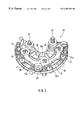
- FIG. 3 in a semi-schematic, developed sectional view, shows the unit comprising the plus and MINUS heat sinks, whose MINUS diodes rest on the bearing plate.
- a rotary current generator for motor vehicles is indicated at 10 . It has a die-cast housing 13 made up of two half-shells 11 , 12 ; the front half-shell 11 is embodied as a bearing plate for a drive bearing 14 , and the rear half-shell 12 is embodied as a bearing plate for a smaller ball bearing 15 .
- the two half-shells of the housing 13 fix a stator lamination packet 16 , which in a known manner receives a three-phase stator winding 17 for generating a rotary current.
- a claw pull rotor 18 is disposed, which is supported by its rotor shaft 19 in the bearings 14 , 15 .
- the rotor shaft 17 in its middle region, carries a magnetically conductive annular core 20 , on which a exciter winding 21 is disposed.
- a respective claw pole board 22 is secured on the rotor shaft 19 , and its claw pull prongs mesh with one another in spaced-apart fashion to form an alternating field.
- a slip ring arrangement 23 is provided on the rear end of the rotor shaft 19 ; of this arrangement, one slip ring each is connected to one end of the exciter winding 21 .
- the slip rings cooperate in a known manner with a carbon brush device, not shown, with which a controller is integrated, with which the direct current flowing in the exciter winding is controlled to suit the demand in the on-board electrical system of the motor vehicle.
- a fan 24 is secured to the face end of the claw pull board 22 ; through corresponding slits on the face end of the half-shell 12 , the fan axially aspirates a cooling air stream 25 and blows it radially outward past the rear winding head of the stator winding 17 through outer slits of the rear half-shell.
- a second fan 24 a is located on the face end of the front claw pull board in the interior of the front half-shell 11 , in order here as well to aspirate a cooling air stream axially through slits in the housing half 11 and blow it radially outward past the front winding head of the stator winding 17 through housing slits located on the outside.
- a rectifier unit 26 which on its input side is connected in a known manner to the winding outputs of the stator winding 17 to rectify the rotary current induced there, is located on the outer face end of the rear half-shell 12 , in the cooling air stream 25 aspirated axially by the rear fan 24 .
- the direct voltage required for supply to the on-board motor vehicle electrical system can be picked up in a known manner.
- the rectifier unit 26 comprises a platelike PLUS heat sink 27 and a MINUS heat sink 28 of thermally conducting metal, preferably aluminum.
- the two opposed heat sinks 27 , 28 are electrically insulated from one another by an insulator plate 29 and secured, together with a circuit board 30 disposed on the upper heat sink 27 , in sandwichlike fashion on the end region of the bearing plate of the machine that forms the rear half-shell 12 .
- MINUS diodes 31 are pressed into preferably fluted bores by their anode terminal.
- a plurality of PLUS diodes 32 are pressed in on the cathode side of the PLUS heat sink 27 .
- the series circuit of one MINUS diode 31 and one PLUS diode 32 each along with their interconnection with end of the stator winding 17 is effected via line wires 33 , which are embedded, except for their terminal ends 33 a , in the circuit board 30 .
- the rectifier unit 26 is covered toward the outside by a plastic protective cap 34 , although this cap is provided with openings 35 suitably disposed on its face end to allow the cooling air stream 25 to enter.
- This protective cap 34 is also secured to the PLUS heat sink 27 by connection screws 37 .
- the lost heat of the rectifier unit 26 is dissipated, on the one hand via a heat-conducting contact of the MINUS diodes 31 and the lower MINUS heat sink 28 to pedestals 12 a and 12 b on the bearing shield of the rear housing half 12 , and on the other via the cooling air stream 25 of the fan 24 from the upper PLUS heat sink 27 , because this upper PLUS heat sink has a plurality of cooling air openings 38 , disposed side by side in the inner circumferential region, for the axial passage therethrough of the cooling air stream 25 .
Landscapes
- Engineering & Computer Science (AREA)
- Power Engineering (AREA)
- Motor Or Generator Cooling System (AREA)
- Synchronous Machinery (AREA)
Abstract
An electric machine, preferably a rotary current generator (10) with a rectifier unit (26) on the rear end region of its bearing plate (12), is proposed in which the dissipation of its lost heat is to be improved. PLUS and MINUS heat sinks (27, 28) with the MINUS and PLUS diodes (31, 32) are screwed firmly in sandwichlike fashion, insulated from one another, to a circuit board (30) for the switching connections between diodes and winding terminals (17A) on the bearing plate (12). In particular to improve the cooling of the MINUS diodes (31), these diodes are in direct metal-to-metal contact by their bases (31 a) with the bearing shield (12) there.
Description
The invention relates to a multi-voltage electrical system for a vehicle.
In a known version of this kind (U.S. Pat. No. 5,451,823), the PLUS and MINUS diodes of a rectifier unit are each secured to a so-called heat sink and electrically connected to it via a housing terminal. The heat sinks are secured in sandwich fashion with an intervening insulator plate on the end face of a bearing plate for a rotary current generator. The lower heat sink is mounted electrically and thermally conductively on the end face of the bearing plate. A circuit board is located on the upper heat sink and has a number of bus bars—embedded in the plastic of the circuit board, for the connection of one PLUS diode and one MINUS diode each on the one hand and for the winding ends of the rotary current winding in the stator of the rotary current generator on the other. This rectifier unit is held together by rivets and is secured with screws to the rotary current generator. For cooling of the upper, curved heat sink, this body is provided with many cooling slits, located side by side in the region of its inside circumference, which are oriented axially to the axis of the electric machine and through which an axial cooling air stream is drawn in from outside to a fan secured to the rotor of the generator. The cooling air blown radially outward by the fan in a known manner through slits on the outer circumference of the bearing plate.
In this known version, it is disadvantageous that the openings, provided for the cooling air to flow through, in the upper heat sink of the unit have relatively small cooling surface areas for heat dissipation, and thus a relatively thick upper heat sink is needed in order to provide an adequate cooling surface area at the cooling air openings. Because of the attendant accumulation of material required, the upper heat sink used here is correspondingly expensive and heavy. Furthermore, to attain a large cooling area for the cooling air flow, the openings in the heat sink are embodied as narrow, radially extending slits, which in turn present relatively high air resistance to the cooling air stream. As a result, the air volume aspirated through these slits is small, and thus the cooling action is also only slight. Using higher-power fans leads to greater expense and increased flow noise.
A further disadvantage of the known generators of this type is that in the rectifier unit, the heat is carried from the MINUS diode bases to the MINUS heat sinks. From there some of the heat is given up—as noted above—directly to the air, while some is transferred via fastening points to the bearing plate and from there is given up to the air. As a result, most of the dissipated heat is absorbed by the air before it enters the interior of the generator. In generators where conversely the MINUS heat sink rests flat on the slip ring bearing plate, the heat flows from the MINUS diode base to the air via the MINUS heat sink and the bearing plate. However, this version requires an especially rigid heat sink and machined bearing faces of large area.
The electric machine according to the invention has the advantage over the prior art that the heat of the MINUS diodes is better dissipated than with a heat sink resting on the housing, because the MINUS diodes here rest directly on the bearing plate themselves. No additionally machined surfaces are needed; a large proportion of the heat generated at the MINUS diodes is not given up to the air from the bearing plate until the air leaves the generator; that is, the internal components receive cooler air. Thus the majority of the heat generated at the MINUS diodes flows directly into the bearing plate, and a lesser portion of the heat flows via the MINUS heat sink to the bearing plate and into the air.
FIG. 1 shows a rotary current generator with a rectifier unit on the rear bearing plate in longitudinal section;
FIG. 2 shows the rectifier unit in a three-dimensional view; and
FIG. 3, in a semi-schematic, developed sectional view, shows the unit comprising the plus and MINUS heat sinks, whose MINUS diodes rest on the bearing plate.
In FIG. 1, a rotary current generator for motor vehicles is indicated at 10. It has a die-cast housing 13 made up of two half- shells 11, 12; the front half-shell 11 is embodied as a bearing plate for a drive bearing 14, and the rear half-shell 12 is embodied as a bearing plate for a smaller ball bearing 15. The two half-shells of the housing 13 fix a stator lamination packet 16, which in a known manner receives a three-phase stator winding 17 for generating a rotary current. In the so-called stator bore of the stator lamination packet, a claw pull rotor 18 is disposed, which is supported by its rotor shaft 19 in the bearings 14, 15. The rotor shaft 17, in its middle region, carries a magnetically conductive annular core 20, on which a exciter winding 21 is disposed. On both sides thereof, a respective claw pole board 22 is secured on the rotor shaft 19, and its claw pull prongs mesh with one another in spaced-apart fashion to form an alternating field.
To supply current to the exciter winding 21, a slip ring arrangement 23 is provided on the rear end of the rotor shaft 19; of this arrangement, one slip ring each is connected to one end of the exciter winding 21. The slip rings cooperate in a known manner with a carbon brush device, not shown, with which a controller is integrated, with which the direct current flowing in the exciter winding is controlled to suit the demand in the on-board electrical system of the motor vehicle. On the inside of the rear half-shell 11, a fan 24 is secured to the face end of the claw pull board 22; through corresponding slits on the face end of the half-shell 12, the fan axially aspirates a cooling air stream 25 and blows it radially outward past the rear winding head of the stator winding 17 through outer slits of the rear half-shell. A second fan 24 a is located on the face end of the front claw pull board in the interior of the front half-shell 11, in order here as well to aspirate a cooling air stream axially through slits in the housing half 11 and blow it radially outward past the front winding head of the stator winding 17 through housing slits located on the outside. A rectifier unit 26, which on its input side is connected in a known manner to the winding outputs of the stator winding 17 to rectify the rotary current induced there, is located on the outer face end of the rear half-shell 12, in the cooling air stream 25 aspirated axially by the rear fan 24. At the output of the rectifier unit 26, the direct voltage required for supply to the on-board motor vehicle electrical system can be picked up in a known manner.
Details of the rectifier unit 26 can be seen in FIGS. 2 and 3. Thus the rectifier unit 26 comprises a platelike PLUS heat sink 27 and a MINUS heat sink 28 of thermally conducting metal, preferably aluminum. The two opposed heat sinks 27, 28 are electrically insulated from one another by an insulator plate 29 and secured, together with a circuit board 30 disposed on the upper heat sink 27, in sandwichlike fashion on the end region of the bearing plate of the machine that forms the rear half-shell 12.
In the MINUS heat sink 28, a plurality of MINUS diodes 31 are pressed into preferably fluted bores by their anode terminal. In the same way, a plurality of PLUS diodes 32 are pressed in on the cathode side of the PLUS heat sink 27. The series circuit of one MINUS diode 31 and one PLUS diode 32 each along with their interconnection with end of the stator winding 17 is effected via line wires 33, which are embedded, except for their terminal ends 33 a, in the circuit board 30. The rectifier unit 26 is covered toward the outside by a plastic protective cap 34, although this cap is provided with openings 35 suitably disposed on its face end to allow the cooling air stream 25 to enter. The circuit board 30, PLUS heat sink 27, insulator plate 29, and MINUS heat sink 28, stacked one above the other, are firmly screwed with fastening screws 36 to the face end of the rear half-shell 12. This protective cap 34 is also secured to the PLUS heat sink 27 by connection screws 37.
The lost heat of the rectifier unit 26 is dissipated, on the one hand via a heat-conducting contact of the MINUS diodes 31 and the lower MINUS heat sink 28 to pedestals 12 a and 12 b on the bearing shield of the rear housing half 12, and on the other via the cooling air stream 25 of the fan 24 from the upper PLUS heat sink 27, because this upper PLUS heat sink has a plurality of cooling air openings 38, disposed side by side in the inner circumferential region, for the axial passage therethrough of the cooling air stream 25. Reference will made here only to FIG. 3, from which it can be seen how the MINUS diodes 31 protrude with their bases 31 a past the contour of the MINUS heat sink 28 and rest with their bases 31 a directly on pedestals 12 b embodied on their chamfers (31 b) of the rear half-shell which forms the bearing plate 12, or in other words are directly in contact with it, and not—as was the case until now—only via the MINUS heat sinks at the fastening points by means of the screws 36. Because of this direct contact of the MINUS diodes 31 with the bearing plate—specifically with initial tension through the small pedestals 12 b on the undersides of the MINUS diodes 31—the majority of the heat generated at these MINUS diodes 31 flows directly into the rear half-shell which forms the bearing plate 12, and a lesser proportion of the heat flows via the MINUS heat sink 28 to the bearing plate and the air. Furthermore, to attain the best possible dissipation of this lost heat from the PLUS heat sink 27 to the cooling air stream 25, axially oriented cooling fins 39 are formed onto the cooling air openings 38 there. By means of these cooling fins, the surface area of the PLUS heat sink 27 exposed to the cooling air stream 25 is greatly increased. Thus the cooling air openings 38 can be enlarged as well, and as a consequence, the proportion of the cooling air stream 25 flowing through these cooling air openings can also be increased.
Claims (2)
1. An electrical machine formed as a rotary current generator, comprising a housing; a rotor rotatably supported in said housing; and a rectifier unit with MINUS and PLUS diodes which are mounted, insulated from one another, on a MINUS and a PLUS heat sink and are secured in a sandwich fashion, together with a circuit board for diode terminals, to an end region of a bearing plate, so that a lost heat of said rectifier unit is dissipatable from the PLUS heat sink which is an upper heat sink partly via a heat-conducting contact of said MINUS heat sink which is a lower heat sink with said bearing plate, and partly via at least one aspirating coolant airstream of a fan, said MINUS diodes secured in said MINUS heat sink and each having a base resting directly on said bearing plate, said MINUS diodes having pedestals which are embodied on said bearing plate and separated from one another by recesses.
2. An electrical machine as defined in claim 1, wherein said MINUS diodes rest with initial tension by said pedestals embodied on chamfers when said MINUS and PLUS heat sinks are screwed together, to said bearing plate.
Applications Claiming Priority (3)
| Application Number | Priority Date | Filing Date | Title |
|---|---|---|---|
| DE19828518A DE19828518A1 (en) | 1998-06-26 | 1998-06-26 | Rectifier modular unit on a three-phase alternator |
| DE19828518 | 1998-06-26 | ||
| PCT/DE1999/000087 WO2000001055A1 (en) | 1998-06-26 | 1999-01-18 | Electrical machine, preferably a three-phase current generator with a rectifier unit |
Publications (1)
| Publication Number | Publication Date |
|---|---|
| US6307289B1 true US6307289B1 (en) | 2001-10-23 |
Family
ID=7872110
Family Applications (1)
| Application Number | Title | Priority Date | Filing Date |
|---|---|---|---|
| US09/485,985 Expired - Fee Related US6307289B1 (en) | 1998-06-26 | 1999-01-18 | Electrical machine with rectifier unit and plus and minus heat sinks with improved lost heat dissipation |
Country Status (5)
| Country | Link |
|---|---|
| US (1) | US6307289B1 (en) |
| EP (1) | EP1032967A1 (en) |
| JP (1) | JP2002519987A (en) |
| DE (1) | DE19828518A1 (en) |
| WO (1) | WO2000001055A1 (en) |
Cited By (30)
| Publication number | Priority date | Publication date | Assignee | Title |
|---|---|---|---|---|
| US6552908B2 (en) * | 2001-02-21 | 2003-04-22 | Transpo Electronics, Inc. | Vehicular modular design multiple application rectifier assembly having outer lead integument |
| US6570279B2 (en) * | 2000-08-31 | 2003-05-27 | Valeo Mando Electrical System Korea Limited | Heat sink plate of alternator for vehicle |
| US20030147212A1 (en) * | 2002-01-28 | 2003-08-07 | Denso Corporation | Rectifying apparatus for a.c. dynamo for vehicle |
| US6617735B2 (en) * | 2000-11-06 | 2003-09-09 | Denso Corporation | Vehicle AC generator |
| KR20030092261A (en) * | 2002-05-29 | 2003-12-06 | 발레오만도전장시스템스코리아 주식회사 | Assembling Structure for Alternator with Heat-sink Plate |
| US20040108775A1 (en) * | 2001-03-02 | 2004-06-10 | Thomas Bilsing | Electric machine |
| WO2004107535A2 (en) * | 2003-05-26 | 2004-12-09 | Valeo Equipements Electriques Moteur | Rotating electrical machine, such as an alternator, particularly for an automobile |
| US20040256924A1 (en) * | 2003-03-18 | 2004-12-23 | Denso Corporation | AC generator for vehicles |
| US20040256925A1 (en) * | 2003-06-18 | 2004-12-23 | Transpo Electronics, Inc. | Rectifier for a vehicle alternator |
| US20050008514A1 (en) * | 2003-01-23 | 2005-01-13 | Baker Hughes Incorporated | Nested bellows expansion member for a submersible pump |
| US20050013118A1 (en) * | 2002-07-16 | 2005-01-20 | Horst Braun | Cooling body and rectifier module for an electrical machine |
| US20050130455A1 (en) * | 2003-12-12 | 2005-06-16 | Spx Corporation | Method and apparatus for high power switching |
| US20060002054A1 (en) * | 2004-07-02 | 2006-01-05 | Visteon Global Technologies, Inc. | Electric machine with integrated electronics in a circular/closed-loop arrangement |
| WO2006021539A1 (en) * | 2004-08-21 | 2006-03-02 | Robert Bosch Gmbh | Rectifier unit and electric machine comprising said type of device |
| US20070046114A1 (en) * | 2005-08-29 | 2007-03-01 | Denso Corporation | Automotive alternator with rectifier having high-strength heat sinks |
| US20070257568A1 (en) * | 2005-01-28 | 2007-11-08 | Mitsubishi Electric Corporation | Electric Rotating Machine |
| US20080303361A1 (en) * | 2007-06-08 | 2008-12-11 | Mitsubishi Electric Corporation | Automotive alternator |
| US20090001857A1 (en) * | 2007-06-26 | 2009-01-01 | Denso Corporation | Automotive alternator having rectifier device |
| US20100001595A1 (en) * | 2008-07-03 | 2010-01-07 | Denso Corporation | Rotary electric machine for vehicles |
| US20100007231A1 (en) * | 2008-07-09 | 2010-01-14 | Mitsubishi Electric Corporation | Alternator |
| US20120091723A1 (en) * | 2010-10-13 | 2012-04-19 | Jean Le Besnerais | Generator, in particular for a wind turbine |
| US20120119350A1 (en) * | 2010-11-11 | 2012-05-17 | Victory Industrial Corporation | Heat Sink Module |
| US20120217829A1 (en) * | 2009-09-17 | 2012-08-30 | Robert Bosch Gmbh | Electric machine |
| US8686609B2 (en) | 2009-09-17 | 2014-04-01 | Robert Bosch Gmbh | Electrical machine |
| DE102007040531B4 (en) * | 2006-09-07 | 2014-10-16 | Denso Corporation | Vehicle alternator with improved operational reliability |
| US20150295480A1 (en) * | 2014-04-11 | 2015-10-15 | Remy Technologies Llc | Electric machine with combined insulator and terminal assembly |
| US9312742B2 (en) | 2013-03-01 | 2016-04-12 | Hamilton Sundstrand Corporation | Connector and spring assembly for a generator |
| CN109905003A (en) * | 2019-04-16 | 2019-06-18 | 珠海市绿田机械有限公司 | Three-phase ac synchronous motor and electrical equipment |
| US10715015B2 (en) * | 2014-04-11 | 2020-07-14 | Borgwarner Inc. | Electric machine with combined insulator and terminal assembly |
| CN111544835A (en) * | 2020-05-26 | 2020-08-18 | 三河市桂宇星体育用品有限公司 | Multi-stage resistance type riding exercise bicycle capable of adjusting resistance through power generation and method |
Families Citing this family (11)
| Publication number | Priority date | Publication date | Assignee | Title |
|---|---|---|---|---|
| DE10111295A1 (en) * | 2001-03-09 | 2002-09-26 | Bosch Gmbh Robert | Structure for cooling current redresser in electric machine e.g. vehicle generator, has fan rotating around axle with air flowing into it and out of it in axial and radial directions, and diodes fitted upstream to fan. |
| FR2827436B1 (en) * | 2001-07-16 | 2004-06-18 | Valeo Equip Electr Moteur | CURRENT RECTIFICATION ARRANGEMENT FOR ROTATING ELECTRIC MACHINES, ESPECIALLY ALTERNATORS FOR MOTOR VEHICLES |
| DE10148668A1 (en) * | 2001-10-02 | 2003-05-08 | Bosch Gmbh Robert | Rectifier means |
| US6911750B2 (en) | 2003-07-03 | 2005-06-28 | Delco Remy International, Inc. | Electronic package for electrical machine |
| DE102004013719A1 (en) * | 2004-03-18 | 2005-10-06 | Sensor-Technik Wiedemann Gmbh | Electrodynamic motor to act as a synchronous, asynchronous or direct current motor, e.g. in a motor vehicle, has electric power of 20 kilowatts and more |
| US8140165B2 (en) | 2005-01-28 | 2012-03-20 | Encore Medical Asset Corporation | Independent protection system for an electrical muscle stimulation apparatus and method of using same |
| ES2599064T3 (en) | 2005-04-19 | 2017-01-31 | Compex Technologies, Inc. | Electrical stimulation device |
| DE102006016239A1 (en) * | 2006-03-31 | 2007-10-04 | Robert Bosch Gmbh | Cooling arrangement for e.g. vehicle generator, has negative diode connected with negative-cooling unit, where negative diode partially extends with its lower side into radial air flow between bearing shield and negative-cooling unit |
| US8620438B1 (en) | 2007-02-13 | 2013-12-31 | Encore Medical Asset Corporation | Method and apparatus for applying neuromuscular electrical stimulation |
| DE102007034323A1 (en) | 2007-07-24 | 2009-01-29 | Robert Bosch Gmbh | Electrical machine e.g. alternator, has cooling bore engaging direct axial air flow without deflection and/or throttling in protective cap and plus-cooling body, where cooling bore is arranged in minus-cooling body |
| DE102011080886A1 (en) * | 2011-08-12 | 2013-02-14 | Robert Bosch Gmbh | Electric machine e.g. alternator, for motor car, has housings comprising end shields, and cooling body attached with fastening element comprising insulating part at one of end shields, where insulating part comprises sleeve part |
Citations (9)
| Publication number | Priority date | Publication date | Assignee | Title |
|---|---|---|---|---|
| US4055778A (en) * | 1971-08-05 | 1977-10-25 | Robert Bosch G.M.B.H. | Generator housing |
| EP0480372A1 (en) * | 1990-10-08 | 1992-04-15 | Hitachi, Ltd. | Semiconductor rectifying device and full-wave rectifier fabricated using the same |
| JPH0698511A (en) * | 1992-09-11 | 1994-04-08 | Hitachi Ltd | Alternator for car |
| EP0671804A1 (en) * | 1994-03-10 | 1995-09-13 | Ford Motor Company | Alternator with internal rectifier bridge |
| US5451823A (en) | 1993-02-11 | 1995-09-19 | Transpo Electronics, Inc. | Vehicular thermoconductive lead frame rectifier assembly |
| DE19705228A1 (en) * | 1997-02-12 | 1998-08-13 | Bosch Gmbh Robert | Electrical machine, preferably a three-phase generator with a rectifier unit |
| US5828564A (en) * | 1997-02-25 | 1998-10-27 | Mitsubishi Denki Kabushiki Kaisha | Rectifier heat dissipation |
| US5949166A (en) * | 1997-09-25 | 1999-09-07 | Denso Corporation | Rectifying apparatus for an automotive AC generator |
| US5955805A (en) * | 1996-12-16 | 1999-09-21 | Valeo Equipements Electriques Moteur | Motor vehicle alternator having a water cooled rear bearing |
Family Cites Families (1)
| Publication number | Priority date | Publication date | Assignee | Title |
|---|---|---|---|---|
| JP3518018B2 (en) * | 1994-03-11 | 2004-04-12 | 株式会社デンソー | AC generator for vehicles |
-
1998
- 1998-06-26 DE DE19828518A patent/DE19828518A1/en not_active Withdrawn
-
1999
- 1999-01-18 EP EP99906057A patent/EP1032967A1/en not_active Withdrawn
- 1999-01-18 JP JP2000557535A patent/JP2002519987A/en active Pending
- 1999-01-18 US US09/485,985 patent/US6307289B1/en not_active Expired - Fee Related
- 1999-01-18 WO PCT/DE1999/000087 patent/WO2000001055A1/en not_active Application Discontinuation
Patent Citations (9)
| Publication number | Priority date | Publication date | Assignee | Title |
|---|---|---|---|---|
| US4055778A (en) * | 1971-08-05 | 1977-10-25 | Robert Bosch G.M.B.H. | Generator housing |
| EP0480372A1 (en) * | 1990-10-08 | 1992-04-15 | Hitachi, Ltd. | Semiconductor rectifying device and full-wave rectifier fabricated using the same |
| JPH0698511A (en) * | 1992-09-11 | 1994-04-08 | Hitachi Ltd | Alternator for car |
| US5451823A (en) | 1993-02-11 | 1995-09-19 | Transpo Electronics, Inc. | Vehicular thermoconductive lead frame rectifier assembly |
| EP0671804A1 (en) * | 1994-03-10 | 1995-09-13 | Ford Motor Company | Alternator with internal rectifier bridge |
| US5955805A (en) * | 1996-12-16 | 1999-09-21 | Valeo Equipements Electriques Moteur | Motor vehicle alternator having a water cooled rear bearing |
| DE19705228A1 (en) * | 1997-02-12 | 1998-08-13 | Bosch Gmbh Robert | Electrical machine, preferably a three-phase generator with a rectifier unit |
| US5828564A (en) * | 1997-02-25 | 1998-10-27 | Mitsubishi Denki Kabushiki Kaisha | Rectifier heat dissipation |
| US5949166A (en) * | 1997-09-25 | 1999-09-07 | Denso Corporation | Rectifying apparatus for an automotive AC generator |
Cited By (57)
| Publication number | Priority date | Publication date | Assignee | Title |
|---|---|---|---|---|
| US6570279B2 (en) * | 2000-08-31 | 2003-05-27 | Valeo Mando Electrical System Korea Limited | Heat sink plate of alternator for vehicle |
| US6617735B2 (en) * | 2000-11-06 | 2003-09-09 | Denso Corporation | Vehicle AC generator |
| US6552908B2 (en) * | 2001-02-21 | 2003-04-22 | Transpo Electronics, Inc. | Vehicular modular design multiple application rectifier assembly having outer lead integument |
| US20040108775A1 (en) * | 2001-03-02 | 2004-06-10 | Thomas Bilsing | Electric machine |
| US6841901B2 (en) | 2001-03-02 | 2005-01-11 | Robert Bosch Gmbh | Electric machine |
| US20030147212A1 (en) * | 2002-01-28 | 2003-08-07 | Denso Corporation | Rectifying apparatus for a.c. dynamo for vehicle |
| US6903472B2 (en) * | 2002-01-28 | 2005-06-07 | Denso Corporation | Rectifying apparatus having wind blocking member |
| KR20030092261A (en) * | 2002-05-29 | 2003-12-06 | 발레오만도전장시스템스코리아 주식회사 | Assembling Structure for Alternator with Heat-sink Plate |
| US7505273B2 (en) * | 2002-07-16 | 2009-03-17 | Robert Bosch Gmbh | Cooling body and rectifier module for an electrical machine |
| US20050013118A1 (en) * | 2002-07-16 | 2005-01-20 | Horst Braun | Cooling body and rectifier module for an electrical machine |
| US20050008514A1 (en) * | 2003-01-23 | 2005-01-13 | Baker Hughes Incorporated | Nested bellows expansion member for a submersible pump |
| US20040256924A1 (en) * | 2003-03-18 | 2004-12-23 | Denso Corporation | AC generator for vehicles |
| US7196441B2 (en) | 2003-03-18 | 2007-03-27 | Denso Corporation | AC generator for vehicles |
| CN100533923C (en) * | 2003-05-26 | 2009-08-26 | 瓦莱奥电机设备公司 | Rotating electrical machine, such as an alternator, particularly for an automobile |
| US7378766B2 (en) | 2003-05-26 | 2008-05-27 | Valeo Equipement Electrique Moteur | Rotating electrical machine, such as an alternator, particularly for an automobile |
| WO2004107535A2 (en) * | 2003-05-26 | 2004-12-09 | Valeo Equipements Electriques Moteur | Rotating electrical machine, such as an alternator, particularly for an automobile |
| US20070069593A1 (en) * | 2003-05-26 | 2007-03-29 | Valeo Equipement Electriquemoteur | Rotating electrical machine, such as an alternator, particularly for an automobile |
| WO2004107535A3 (en) * | 2003-05-26 | 2005-02-24 | Valeo Equip Electr Moteur | Rotating electrical machine, such as an alternator, particularly for an automobile |
| US20040256925A1 (en) * | 2003-06-18 | 2004-12-23 | Transpo Electronics, Inc. | Rectifier for a vehicle alternator |
| WO2005001936A1 (en) * | 2003-06-18 | 2005-01-06 | Wetherill Associates, Inc. | Rectifier for a vehicle alternator |
| US20050130455A1 (en) * | 2003-12-12 | 2005-06-16 | Spx Corporation | Method and apparatus for high power switching |
| US6953346B2 (en) * | 2003-12-12 | 2005-10-11 | Spx Corporation | Method and apparatus for high power switching |
| US20060002054A1 (en) * | 2004-07-02 | 2006-01-05 | Visteon Global Technologies, Inc. | Electric machine with integrated electronics in a circular/closed-loop arrangement |
| US7180212B2 (en) | 2004-07-02 | 2007-02-20 | Visteon Global Technologies, Inc. | Electric machine with integrated electronics in a circular/closed-loop arrangement |
| WO2006021539A1 (en) * | 2004-08-21 | 2006-03-02 | Robert Bosch Gmbh | Rectifier unit and electric machine comprising said type of device |
| US20090167122A1 (en) * | 2004-08-21 | 2009-07-02 | Dieter Schurig | Rectifier and electric machine comprising said type of device |
| US20070257568A1 (en) * | 2005-01-28 | 2007-11-08 | Mitsubishi Electric Corporation | Electric Rotating Machine |
| US7638910B2 (en) * | 2005-01-28 | 2009-12-29 | Mitsubishi Electric Corporation | Electric rotating machine |
| US20070046114A1 (en) * | 2005-08-29 | 2007-03-01 | Denso Corporation | Automotive alternator with rectifier having high-strength heat sinks |
| US7605502B2 (en) | 2005-08-29 | 2009-10-20 | Denso Corporation | Automotive alternator with rectifier having high-strength heat sinks |
| DE102007040531B4 (en) * | 2006-09-07 | 2014-10-16 | Denso Corporation | Vehicle alternator with improved operational reliability |
| US7723876B2 (en) * | 2007-06-08 | 2010-05-25 | Mitsubishi Electric Corporation | Automotive alternator |
| US20100176671A1 (en) * | 2007-06-08 | 2010-07-15 | Mitsubishi Electric Corporation | Automotive alternator |
| US7902701B2 (en) * | 2007-06-08 | 2011-03-08 | Mitsubishi Electric Corporation | Automotive alternator |
| US20080303361A1 (en) * | 2007-06-08 | 2008-12-11 | Mitsubishi Electric Corporation | Automotive alternator |
| US20090001857A1 (en) * | 2007-06-26 | 2009-01-01 | Denso Corporation | Automotive alternator having rectifier device |
| US7839032B2 (en) | 2007-06-26 | 2010-11-23 | Denso Corporation | Automotive alternator having rectifier device |
| US20100001595A1 (en) * | 2008-07-03 | 2010-01-07 | Denso Corporation | Rotary electric machine for vehicles |
| US8106547B2 (en) | 2008-07-03 | 2012-01-31 | Denso Corporation | Rotary electric machine for vehicles |
| US20100007231A1 (en) * | 2008-07-09 | 2010-01-14 | Mitsubishi Electric Corporation | Alternator |
| US7741742B2 (en) * | 2008-07-09 | 2010-06-22 | Mitsubishi Electric Corporation | Alternator |
| US8686609B2 (en) | 2009-09-17 | 2014-04-01 | Robert Bosch Gmbh | Electrical machine |
| US20120217829A1 (en) * | 2009-09-17 | 2012-08-30 | Robert Bosch Gmbh | Electric machine |
| US9184643B2 (en) * | 2009-09-17 | 2015-11-10 | Robert Bosch Gmbh | Electric machine |
| US20120091723A1 (en) * | 2010-10-13 | 2012-04-19 | Jean Le Besnerais | Generator, in particular for a wind turbine |
| US20120119350A1 (en) * | 2010-11-11 | 2012-05-17 | Victory Industrial Corporation | Heat Sink Module |
| US9312742B2 (en) | 2013-03-01 | 2016-04-12 | Hamilton Sundstrand Corporation | Connector and spring assembly for a generator |
| CN106170909A (en) * | 2014-04-11 | 2016-11-30 | 雷米技术有限公司 | With composite insulator and the motor of terminal assemblies |
| US20150295480A1 (en) * | 2014-04-11 | 2015-10-15 | Remy Technologies Llc | Electric machine with combined insulator and terminal assembly |
| US9627948B2 (en) * | 2014-04-11 | 2017-04-18 | Remy Technologies Llc | Electric machine with combined insulator and terminal assembly |
| CN106170909B (en) * | 2014-04-11 | 2019-05-10 | 雷米技术有限公司 | Motor with composite insulator and terminal assemblies |
| CN109904988A (en) * | 2014-04-11 | 2019-06-18 | 雷米技术有限公司 | Method of the manufacture for the Electronic Packaging of motor |
| US10715015B2 (en) * | 2014-04-11 | 2020-07-14 | Borgwarner Inc. | Electric machine with combined insulator and terminal assembly |
| CN109904988B (en) * | 2014-04-11 | 2021-08-31 | 雷米技术有限公司 | Method of manufacturing an electronic package for an electrical machine |
| CN109905003A (en) * | 2019-04-16 | 2019-06-18 | 珠海市绿田机械有限公司 | Three-phase ac synchronous motor and electrical equipment |
| CN111544835A (en) * | 2020-05-26 | 2020-08-18 | 三河市桂宇星体育用品有限公司 | Multi-stage resistance type riding exercise bicycle capable of adjusting resistance through power generation and method |
| CN111544835B (en) * | 2020-05-26 | 2023-08-04 | 三河市桂宇星体育用品有限公司 | Multi-stage resistance riding exercise bicycle capable of adjusting resistance through power generation and method |
Also Published As
| Publication number | Publication date |
|---|---|
| JP2002519987A (en) | 2002-07-02 |
| EP1032967A1 (en) | 2000-09-06 |
| WO2000001055A1 (en) | 2000-01-06 |
| DE19828518A1 (en) | 1999-12-30 |
Similar Documents
| Publication | Publication Date | Title |
|---|---|---|
| US6307289B1 (en) | Electrical machine with rectifier unit and plus and minus heat sinks with improved lost heat dissipation | |
| US6285100B1 (en) | Electrical machine, preferably a rotary current generator with a rectifier component and with upper heat sink provided with axial cooling fins | |
| US7417344B2 (en) | Electronic package for electrical machine | |
| US6812604B2 (en) | Rectifier assembly having heat-dissipating structure for an alternator | |
| US7414339B2 (en) | Vehicular rotating electrical machine apparatus | |
| JP2004147486A (en) | Automotive ac generator | |
| US6563241B2 (en) | A. C. generator for vehicles having loose-free terminal structure | |
| JP2007049885A (en) | Vehicle-use tandem rotary electric machine | |
| US5258673A (en) | Rectifier device in vehicle AC generator | |
| KR100608925B1 (en) | AC generator for vehicle | |
| KR100363815B1 (en) | Alternator | |
| US7570488B2 (en) | Alternator rectifier | |
| US7957170B2 (en) | Cooling-fin mounted rectifier for vehicular AC generators | |
| JP3975974B2 (en) | AC generator for vehicles | |
| US20040232783A1 (en) | Electric machine, especially an alternator for motor vehicles | |
| US6897583B2 (en) | Electrical machine with air-cooled control chip | |
| KR100585415B1 (en) | Alternator | |
| US9000719B2 (en) | Electric machine | |
| JP2002142424A (en) | Alternator for vehicle | |
| US7091637B2 (en) | AC generator for vehicle having rectifying unit | |
| US20050127763A1 (en) | Bridge rectifier for charging system alternator | |
| JPH0572184B2 (en) | ||
| KR20000001105U (en) | Slip ring end frame for alternator. | |
| KR19990037978U (en) | Automotive alternator stop |
Legal Events
| Date | Code | Title | Description |
|---|---|---|---|
| AS | Assignment |
Owner name: ROBERT BOSCH GMBH, GERMANY Free format text: ASSIGNMENT OF ASSIGNORS INTEREST;ASSIGNOR:SKALA, PETER;REEL/FRAME:010673/0169 Effective date: 20000111 |
|
| REMI | Maintenance fee reminder mailed | ||
| LAPS | Lapse for failure to pay maintenance fees | ||
| STCH | Information on status: patent discontinuation |
Free format text: PATENT EXPIRED DUE TO NONPAYMENT OF MAINTENANCE FEES UNDER 37 CFR 1.362 |
|
| FP | Lapsed due to failure to pay maintenance fee |
Effective date: 20051023 |