US7527465B2 - Book-binding apparatus using adhesive agent - Google Patents
Book-binding apparatus using adhesive agent Download PDFInfo
- Publication number
- US7527465B2 US7527465B2 US11/507,615 US50761506A US7527465B2 US 7527465 B2 US7527465 B2 US 7527465B2 US 50761506 A US50761506 A US 50761506A US 7527465 B2 US7527465 B2 US 7527465B2
- Authority
- US
- United States
- Prior art keywords
- adhesive agent
- book
- section
- tank
- binding apparatus
- Prior art date
- Legal status (The legal status is an assumption and is not a legal conclusion. Google has not performed a legal analysis and makes no representation as to the accuracy of the status listed.)
- Expired - Fee Related, expires
Links
- 239000000853 adhesive Substances 0.000 title claims abstract description 237
- 239000011248 coating agent Substances 0.000 claims description 33
- 238000000576 coating method Methods 0.000 claims description 33
- 239000007787 solid Substances 0.000 claims description 21
- 238000010438 heat treatment Methods 0.000 claims description 9
- 238000001514 detection method Methods 0.000 claims description 2
- 230000001070 adhesive effect Effects 0.000 abstract description 25
- 238000000034 method Methods 0.000 description 13
- 239000003795 chemical substances by application Substances 0.000 description 10
- 238000003825 pressing Methods 0.000 description 7
- 239000004831 Hot glue Substances 0.000 description 6
- 238000002844 melting Methods 0.000 description 6
- 230000008018 melting Effects 0.000 description 6
- 230000002159 abnormal effect Effects 0.000 description 2
- 238000004140 cleaning Methods 0.000 description 2
- 238000007599 discharging Methods 0.000 description 2
- 239000012943 hotmelt Substances 0.000 description 2
- 238000005304 joining Methods 0.000 description 2
- 230000003213 activating effect Effects 0.000 description 1
- 238000005520 cutting process Methods 0.000 description 1
- 238000001035 drying Methods 0.000 description 1
- 230000005674 electromagnetic induction Effects 0.000 description 1
- 239000007788 liquid Substances 0.000 description 1
- 239000000463 material Substances 0.000 description 1
- 230000003287 optical effect Effects 0.000 description 1
- 230000001105 regulatory effect Effects 0.000 description 1
- 230000000630 rising effect Effects 0.000 description 1
- 238000009966 trimming Methods 0.000 description 1
Images


Classifications
-
- B—PERFORMING OPERATIONS; TRANSPORTING
- B42—BOOKBINDING; ALBUMS; FILES; SPECIAL PRINTED MATTER
- B42C—BOOKBINDING
- B42C9/00—Applying glue or adhesive peculiar to bookbinding
- B42C9/0006—Applying glue or adhesive peculiar to bookbinding by applying adhesive to a stack of sheets
-
- B—PERFORMING OPERATIONS; TRANSPORTING
- B42—BOOKBINDING; ALBUMS; FILES; SPECIAL PRINTED MATTER
- B42C—BOOKBINDING
- B42C9/00—Applying glue or adhesive peculiar to bookbinding
- B42C9/0006—Applying glue or adhesive peculiar to bookbinding by applying adhesive to a stack of sheets
- B42C9/0012—Applying glue or adhesive peculiar to bookbinding by applying adhesive to a stack of sheets with a roller
- B42C9/0018—Applying glue or adhesive peculiar to bookbinding by applying adhesive to a stack of sheets with a roller for binding stacks of sheets one at the time
- B42C9/0025—Applying glue or adhesive peculiar to bookbinding by applying adhesive to a stack of sheets with a roller for binding stacks of sheets one at the time and subsequently applying a cover
Definitions
- the present invention relates to a book-binding apparatus using adhesive agent in which the replenishing amount of the adhesive agent to be coated on a spine of the stacked sheets is controlled.
- a method of book-binding in which a liquid adhesive agent is used.
- a solid member, being a hot-melt material, to be melted as an adhesive agent is becoming more widely used.
- the hot-melt solid adhesive agent is melted at a predetermined temperature, and which is then applied on the stacked bundle of sheets.
- temperature control of melting point of the solid adhesive agent is extremely important.
- a replenishing section is widely used in which a predetermined amount of the adhesive agent is supplied, independently of the used amount of the adhesive agent.
- a large predetermined amount is established by the operator, temperature for melting the adhesive agent in the tank largely drops so that the adhesive agent does not melt at its required temperature, and thereby, an abnormal odor is generated from the adhesive agent.
- a small predetermined amount is established, the number of times of the replenishment increases, which results in short durability of the parts incorporated in the apparatus, as well as results in an increase of inherent operating sounds.
- Patent Document 1 after the adhesive agent is coated on the spine of the stacked bundle of sheets, the adhesive agent is required to be dried in a short time. That is, a dryer section which includes a heater, a blower and a duct, and an adhesive section which includes an adhesive roller to apply the adhesive agent on the spine, and an adhesive tank, are arranged in this order. While a cramp section secures the stacked bundle of sheets, a moving section of the sheet securing section drives a sheet securing section from the cramp section, and further drives back and forth to the dryer section and the adhesive section. A control section controls the moving section of the sheet securing section and the dryer section while the reciprocating movement of the sheet securing section so that the coating of the adhesive agent and drying can be effectively controlled.
- Patent Document 1 shows that via forcing the adhered section to be dried in a short time, generation of abnormal odor is controlled.
- Patent Document 2 shows a book-binding apparatus in which an adhesive agent pool and an integral roller moves under the stacked bundle of sheets to apply the adhesive agent onto the spine of the stacked bundle of sheets, and by detecting thickness of the stacked bundle of sheets, during the reciprocating movement of the adhesive agent pool, the rotation of the roller is differently controlled for effective bonding.
- an electromagnetic induction coil is used for the heat source to melt the adhesive agent
- a thermo-couple method is used for the temperature control section.
- the top level of the adhesive agent is lowered than the position of the thermo couple, then the detected temperature becomes lower than the predetermined temperature, and an appropriate signal is sent to the control section.
- the control section receives this signal and operates an adhesive agent replenishing unit to supply the adhesive agent.
- a pasting bookmaking apparatus which includes: an adhesive agent container for housing the adhesive agent, featuring an open section, a container loading section for loading the adhesive agent container at a predetermined position, a supplying tube for sending the adhesive agent ejected from the open section, an adhesive agent discharging section connected to the supplying tube for discharging the adhesive agent from a nozzle top, a temperature sensor and a heating section placed adjacent to the adhesive agent container, and a control section wherein when the temperature sensor detects that the temperature is lower than a predetermined temperature, the control section activates a power source of the heating section, and makes the heating section to increase the temperature of the adhesive agent container.
- the back face of the paper bundle is coated with the adhesive agent by integrally reciprocating an adhesive reservoir and a roller on the lower side of the paper bundle, an adhesive feeding unit provided from a standby position of the adhesive reservoir to a facing position by pinching the paper bundle, is further provided.
- the adhesive feeding unit is composed of a storing section for storing a particulate adhesive agent, included carrying paths for the particulate adhesive agent provided below and in a declining slope from the storing section, and a feeding hole to allow the particulate adhesive to pass through the inclined carrying paths.
- the adhesive feeding unit feeds a specified amount of the particulate adhesive agent into the adhesive reservoir at appropriate timing when the adhesive reservoir is moved, and which exists near the feeding hole.
- Patent Document 1 Unexamined Japanese Patent Application Publication No. 9-156249
- Patent Document 2 Unexamined Japanese Patent Application Publication No. 2005-178187
- Patent Document 3 Unexamined Japanese Patent Application Publication No. 2002-177847
- Patent Document 4 Unexamined Japanese Patent Application Publication No. 2004-209746
- An object of the present invention is to provide a book-binding apparatus in which a control section is used for keeping the amount of adhesive agent at a constant value in an adhesive agent tank, based on the shape of a book to be bundled, such as the thickness of the book. As the shape of the book, the thickness is more preferable than the number of pages or the quality of paper.
- a book-binding apparatus using adhesive agent including:
- an adhesive agent tank to store a heat melting adhesive agent
- a first control section to control the temperature based on a temperature detection signal sent from the first temperature sensor, wherein the first control section controls the heating section so as to make the temperature of the adhesive agent in the tank to become a predetermined temperature
- a second temperature sensor mounted at a position adjacent to a top level of the melted adhesive agent
- an adhesive agent transporting section to transport the adhesive agent to the adhesive agent tank
- a second control section to control the adhesive agent transporting section to transport the adhesive agent to the adhesive agent tank based on a shape of a book to be bound, when the temperature detected by the second temperature sensor is equal to or lower than a set temperature.
- the book-binding apparatus including:
- an adhesive agent tank to store a heat melting adhesive agent
- a temperature sensor mounted at a position adjacent to a top level of a melted adhesive agent
- an adhesive agent transporting section to transport a adhesive agent to the adhesive agent tank
- control section to control the adhesive agent transporting section to transport the adhesive agent to the adhesive agent tank based on a shape of a book, when the temperature detected by the temperature sensor is equal to or lower than a set temperature.
- FIG. 1 is a cross-sectional view of the book-binding apparatus relating to the embodiment of the present invention
- FIG. 2( a )-( d ) show coating procedures of the adhesive agent
- FIG. 3 is a plane view of the coating section, which is viewed from the top;
- FIG. 4 is a cross-sectional view taken along line Y-Y of FIG. 3 ;
- FIG. 5 is a perspective view of the coating section
- FIG. 6 is a cross-sectional view taken along line X-X of FIG. 3 ;
- FIG. 7( a )-( b ) show the adhesive agent replenishing section
- FIG. 8 is a cross-sectional view of a cover housing section and a cover supporting unit
- FIG. 9 is across-sectional view of the cover supporting unit which is viewed from direction A in FIG. 8 ;
- FIG. 10( a ) is a top view of the cover supporting section, while FIG. 10( b ) is a cross-sectional view taken along line C-C of FIG. 10( a );
- FIG. 11( a )-( c ) show the procedures to attach the cover on the stacked bundle of sheets
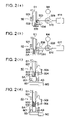
- FIG. 12( a )-( d ) show the procedures after the cover is attached
- FIG. 13 is a flow chart of the temperature control of the adhesive agent tank, wherein the first temperature sensor and the first temperature control section are used;
- FIG. 14 is a flow chart of the replenishing control of the adhesive agent, wherein the second temperature sensor and the second temperature control section are used.
- FIG. 15 is a flow chart of the replenishing control of the adhesive agent.
- FIG. 1 is a total view of the book-binding apparatus relating to the embodiments of the present invention.
- Book-binding apparatus B includes conveyance section 10 for conveying sheets S 1 ejected from an image forming apparatus (which is not illustrated) onto ejection tray 20 or sheet flipping section 40 , stacking section 50 to stack and bundle sheet S 1 which is fed individually from sheet flipping section 40 , adhesive agent coating section to, cover housing section 80 to store covers S 2 , cover supporting unit 90 for supporting the cover, and book ejecting section 100 for storing the completed books, whose cover and the sheets have been joined.
- conveyance section 10 for conveying sheets S 1 ejected from an image forming apparatus (which is not illustrated) onto ejection tray 20 or sheet flipping section 40 , stacking section 50 to stack and bundle sheet S 1 which is fed individually from sheet flipping section 40 , adhesive agent coating section to, cover housing section 80 to store covers S 2 , cover supporting unit 90 for supporting the cover, and book ejecting section 100 for storing the completed books, whose cover and the sheets have been joined.
- Sheet S 1 ejected from an image forming apparatus, is further ejected onto ejection tray 20 through ejection route 12 by path changing gate 11 provided on conveyance section 10 , or sheet S 1 is conveyed to sheet flipping section 40 which allows sheet S 1 to go and return.
- sheet S 1 is ejected onto ejection tray 20 in a mode except for book-binding.
- sheet S 1 is conveyed to sheet flipping section 40 through conveyance route 13 , sheet S 1 is switch-backed to be conveyed to stacking section 50 .
- stacking section 50 a predetermined volume of sheets S 1 are to be stacked, that is, after the predetermined number of sheets S 1 are stacked on stacking section 50 , stacking section 50 nips stacked sheets S 1 and rotates them to perpendicularly support bundled sheets S 1 .
- Adhesive agent is coated by coating section 60 onto the spine (which is supported on plate 506 in FIG. 1 ) of sheets S 1 , which is perpendicularly supported by stacking section 50 .
- Cover S 2 is adhered onto newly bound sheets S 1 so that book S 3 is formed, and which is ejected onto book ejecting section 100 .
- S 1 represents the sheet to be structured as a book
- S 2 represents the cover sheet of the book
- S 3 represents a formed book, including sheets S 1 and cover S 2 .
- control described above is conducted by a control section (which is not illustrated) in the book-binding apparatus, which is also conducted in the following explanation.
- Sheet S 1 is conveyed through conveyance route 13 , and further conveyed by paired ejection rollers 14 and paired swinging pressure rollers 401 to climb slanted reversing plate 402 , after which, sheet S 1 is conveyed downward by the reverse rotation of paired swinging pressure rollers 401 , and is dropped onto stacking section 50 .
- Slanted sheets S 1 are supported in stacking section 50 by a sheet supporting section composed of supporting plate 502 and receiving plate 506 .
- sheets S 1 are formed as a set of sheets.
- the number of sheets S 1 to be formed as a set have been determined by the total number of the document counted by an automatic document feeding device provided in the image forming apparatus, the number of the documents obtained from document image information via a personal computer, and the number of the documents previously inputted by an operator.
- Numeral 504 represents a holding member to hold stacked sheets S 1 , wherein every time when sheet S 1 is supplied to stacking section 50 , holding member 504 holds sheet S 1 respectively, by touching and separating from sheet S 1 .
- Numeral 505 represents a plate to jog the set of sheets S 1 .
- holding plate 503 moves to nip and support the stacked set of sheets S 1 .
- stacking section 50 rotates around axis 501 so that the stacked set of sheets S 1 is changed to a vertical position from the slanted position.
- FIG. 2 shows the procedure for coating the adhesive agent, while the stacked set of sheets S 1 is perpendicularly supported on stacking section 50 .
- Holding plate 503 activated by motor M 4 , presses the stacked set of sheets S 1 , and when driving torque of the press action reaches a predetermined value, holding plate 503 is stopped, and the stacked set of sheets S 1 is strongly sandwiched between supporting plate 502 and holding plate 503 .
- the position where holding plate 503 stops is detected by encoder 509 , and the position is memorized in a memory device of position detecting section 511 .
- receiving plate 506 rotates 90° to the position as shown in FIG. 2( b ).
- spine SA (which is the surface formed of edges of stacked set of sheets S 1 , and to be coated with an adhesive agent) of the stacked set of sheets S 1 is not in contact with adhesive agent coating roller 601 .
- coating section 60 storing melted hot-melt adhesive agent AD is driven upward by motor M 2 , after which adhesive agent coating roller 601 comes into contact with spine SA, and moves in the direction perpendicular to the surface of FIG. 2( d ), and thereby spine SA is coated with hot-melted adhesive agent AD.
- FIG. 3 is a plane view of coating section 60 which is viewed from the top
- FIG. 4 is a cross-sectional view taken along line Y-Y of FIG. 3
- FIG. 5 is a perspective view of coating section 60
- FIG. 6 is a cross-sectional view taken along line X-X of FIG. 3 , in which first temperature sensor TS 1 and second temperature sensor TS 2 are provided.
- endless belt 67 allows coating section 60 to move, since connecting member 612 is fixed to a point of endless belt 67 , and coating section 60 connected to sliding section 608 moves along slide rail 610 .
- Belt 67 is trained about pulleys 613 and 614 , which are provided near the extreme ends of slide rail 610 , and pulley 614 is driven by belt drive motor M 3 .
- numeral 604 represents an adhesive agent leveling roller to even out hot-melt adhesive agent AD supplied onto book spine SA, and gear G 1 (shown in FIG. 5 ) is mounted on rotation shaft 604 A.
- Numeral 618 represents a regulating plate to control the amount of hot-melt adhesive agent AD which is supplied onto adhesive agent coating roller 601 , and roller 618 is mounted at a predetermined clearance from roller 601 .
- Numeral 619 represents a cleaning plate to remove any remaining hot-melt adhesive agent AD on adhesive agent leveling roller 604 , and cleaning plate 619 comes into contact with adhesive agent leveling roller 604 at a predetermined pressure.
- Rollers 601 and 604 are driven by motor M 1 , and their rotation is set to be the same as the traveling direction of coating section 60 .
- Numeral 602 represents a tank to store hot-melt adhesive agent AD in the melted state. Heater 603 to heat tank 602 is placed below tank 602 .
- gear G 4 is rotated by motor M 1 through two timing pulleys and a timing belt.
- Idler gear G 2 is rotated by gear G 4 .
- Gear G 1 mounted on the shaft of adhesive leveling roller 604 , is rotated by gear G 4 .
- Gear G 3 mounted on the shaft of adhesive agent coating roller 601 , is rotated by idler gear G 2 . Accordingly adhesive agent coating roller 601 and adhesive leveling roller 604 are rotated by motor M 1 .
- first temperature sensor TS 1 is provided at the bottom of tank 602 .
- First temperature control section TC 1 shown in FIG. 4 controls the temperature of adhesive agent stored in tank 602 by activating or de-activating the power supply of heater 603 based on the electrical signals from first temperature sensor TS 1 .
- second temperature sensor TS 2 is provided at the position adjacent to the top level of the melted adhesive agent.
- Second temperature control section TC 2 shown in FIG. 4 controls the temperature of adhesive agent, based on electrical signals from second temperature sensor TS 2 .
- adhesive agent AD As adhesive agent AD is consumed, the top level of adhesive agent AD drops, and a distance is created between the top level of adhesive agent AD and second temperature sensor TS 2 . Accordingly, when the temperature detected by sensor TS 2 drops, and reaches a predetermined temperature, adhesive agent AD is replenished to tank 602 .
- coating section 60 is on standby at the right-most position (being the initial position) also known as the home position.
- coating section 60 is conveyed by belt 67 (being a second moving section) activated by motor M 3 , toward the left away from the home position.
- Coating section 60 is conveyed based on a signal that sheet sensor SE, located just downstream of reversing plate 402 (see FIG. 1) , detects the passage of the top of sheet S 1 which is the last one of stacked sheets S 1 on stacking section 50 . While coating section 60 is conveyed toward the left, adhesive agent coating roller 601 is not in contact with spine SA of stacked sheets S 1 .
- coating roller 601 is elevated by motor M 2 to come into contact with spine SA of sheets S 1 , and thereby coats adhesive agent AD on spine SA.
- agent coating operation starts at the start of the agent coating operation in FIG. 7( a ), when stacked sheets S 1 are vertically positioned to be coated, as well as when the conveyance of the cover sheet which was cut by cutter 81 is terminated, the adhesive coating operation starts.
- numeral 66 represents a chute
- numeral 64 represents a valve to replenish a predetermined volume of the adhesive agent.
- numeral 68 represents a conveyance section which conveys the solid pieces of adhesive agent to tank 602
- vibrator 69 is provided midstream of the conveyance path to prevent the solid pieces of adhesive agent from clogging in chute 66 .
- Numeral 70 serves as a counter to count the number of solid pieces of the adhesive agent, is an optical sensor including a light emitting section and a light receiving section.
- the solid piece of the adhesive agent passes counter 70 , the solid piece interrupts the light ray between the light emitting section and the light receiving section, whereby the number of pieces is counted based on the signals received by the light receiving section.
- valve 64 is opened, and the some pieces of the adhesive agent pass counter 70 .
- Signals representing the counted number are transmitted to the control section of the book-binding apparatus so that at least the necessary number of pieces of adhesive agent are replenished into tank 602 , after which valve 64 is closed by the signal from the control section.
- stacked sheets S 1 are supported between supporting plate 502 and holding plate 503 , and the position of holding plate 503 is detected by encoder 509 , and thereby the thickness of the stacked sheets S 1 is counted based on the memory device of position detecting section 511 .
- FIG. 8 is a cross-sectional view of cover housing section 80 to store cover S 2 and cover supporting unit 90
- FIG. 9 is across-sectional view of cover supporting unit 90 which is viewed from direction A in FIG. 8 .
- cover S 2 which is stored in cover sheet tray 801 of cover housing section 80 provided at the bottom of the book-binding apparatus, is picked up by paired supply-conveyance rollers 82 , and is aligned in cover supporting unit 90 , after which cover S 2 is switched-back to cutter 81 as a cover cutting section, whereby cover S 2 is cut the adequate length for stacked sheets S 8 .
- cover S 2 is conveyed by paired conveyance rollers 84 , and horizontally placed in cover supporting section 901 which is shown by dashed lines in FIG. 8 .
- Cover supporting section 901 is structured of plural members, such as pressuring members 91 and 92 , as well as cams 93 and 94 for driving pressuring members 91 and 92 .
- cutter 81 cuts cover S 2 to the proper length, based on information of the size of cover S 2 , information of the size of sheet S 1 , and information of the thickness of stacked sheets S 1 stored in position detecting section 511 . Trimmings from cover S 2 fall into box 83 .
- Cover S 2 which was cut to a predetermined length, is conveyed by upper guide plate 955 and lower guide plate 956 , each keeping the distance of nearly 5 mm. Cover S 2 is conveyed by paired cover conveyance roller 951 and driven roller 952 , the latter of which is provided on the top of cover holding members 95 and 96 .
- cover S 2 arrives at a predetermined position, which is determined based on information of the size of cover S 2 and information of the thickness of stacked sheets S 1 , cover S 2 is controlled to be stopped.
- cover holding member 97 is positioned under cover S 2 to hold up cover S 2 from beneath.
- FIG. 10( a ) is a top view of cover supporting section 901
- FIG. 10( b ) is a cross-sectional view taken along line C-C of FIG. 10( a ).
- Belts 98 A and 98 B correct any miss alignment of conveyed cover S 2 , and also convey bound book S 3 to book ejecting section 100 (see FIG. 1 ).
- alignment members 981 A and 982 B are provided to align both edges of cover S 2 perpendicular to the conveyance direction of cover S 2 .
- Belts 98 A and 98 B are entrained on convex rollers which are mounted on alignment members 981 A and 981 B, respectively.
- Alignment members 981 A and 981 B correct any miss alignment of each conveyed cover S 2 .
- cover supporting member 901 which is detailed later, goes up, alignment members 981 A and 981 B, as well as belts 98 A and 98 B are retracted to the positions shown by double-dashed lines in FIG. 10( a ).
- cover S 2 while pressed by pressing members 95 and 96 , goes up with cover supporting member 901 , conveyed by belts 99 A and 99 B (being first conveyance sections, see FIG. 9 ) driven by motors M 10 .
- FIG. 11( a ) shows the condition in that hot-melt adhesive agent AD has been applied.
- cover supporting section 901 supports cover S 2 at a beneath position, which is away from the spine of bundled stacked sheets S 1 .
- cover holding members 95 and 96 hold cover S 2 from above to keep cover S 2 in a flat condition.
- Cover S 2 goes up and comes into contact with spine SA of stacked sheets S 1 , while cover holding members 95 , 96 and 97 are released from holding by a motor (which is not illustrated), and whose final positions are shown in FIG. 11( b ).
- cover S 2 has been pushed up from beneath by cover holding member 97 , which is positioned under cover S 2 .
- Cover supporting section 901 further goes up about several mm higher than the position shown in FIG. 11( b ). The position gone up several mm is shown in FIG. 11( c ).
- pressing members 91 and 92 press cover S 2 from side to side to generate creases at a border of the spine cover and the front cover, as well as at the border of the spine cover and the back cover, after which cover S 2 is contacted to the adhesive agent applied on spine SA of sheets S 1 to produce book S 3 . Pressuring members 91 and 92 press against cover S 2 for 5 seconds with the pressure strength of about 200 Nf.
- pressing members 91 and 92 are horizontally moved by cams 93 and 94 (see FIG. 10 ) driven by a motor (which is not illustrated). It is also possible to structure racks on pressing members 91 and 92 , and the rotation of pinion gears engaging with the racks drives pressing member 91 and 92 .
- cover S 2 after cover S 2 is attached is detailed.
- cover supporting section 901 goes down about 100 mm driven by belts 99 A and 99 B, and returns to the home position, as shown in FIG. 12( a ).
- cover holding members 95 , 96 and 97 are turned from a vertical position to a horizontal position, and are again rotated counterclockwise, and cover lift-up member 971 also goes up.
- belts 98 A and 98 B are driven to a position which is narrower than the width of cover S 2 , to raise cover supporting member 901 about 70 mm.
- Book ejecting plate 101 is raised or lowered by the belt drive. After book ejecting plate 101 , on which book S 3 is placed, is lowered, book S 3 is shifted onto belt 102 , and is conveyed by belt 102 to be ejected from the book-binding apparatus.
- the thickness of the book and the replenishing amount of the adhesive agent will be detailed.
- Table 1 shows the relationship between the thickness of the book and the replenishing amount of the adhesive agent.
- the weight of a piece of the adhesive agent is 0.5 g/piece.
- the melting temperature of the adhesive agent is equal to or higher than 80° C., and the temperature for supplying the adhesive agent is determined to be equal to or lower than 160° C.
- FIG. 13 is a flow chart of the temperature control of adhesive agent tank, wherein the first temperature sensor and the first temperature control section are used.
- the first temperature sensor checks whether the adhesive agent temperature is in the control temperature (step S 02 ). If it is lower than the control temperature, a heater is activated (step S 03 ), while if it is higher than the control temperature, the heater is de-activated (step S 04 ).
- FIG. 14 is a flow chart of the replenishing control of the adhesive agent, wherein the second temperature sensor and the second temperature control section are used.
- “WUT” means the time in which the temperature of the adhesive agent reaches the control temperature, and adhesive operation can be performed.
- step S 11 After the replenishing control of the adhesive agent is started (step S 11 ), it is checked whether the warm-up time for the adhesive agent tank is completed or not (step S 12 ), if the warm-up time is completed, the second temperature sensor measures whether the temperature of the adhesive agent is higher than the control temperature (step S 13 ), and if it is higher than the control temperature, this condition is maintained (step S 14 ), and if it is lower than the control temperature, determination is made whether replenishment is to be performed or not (step S 15 ), wherein if replenishment is necessary, replenishment of the adhesive agent is performed (steps S 16 and S 17 ).
- FIG. 15 is a flow chart of replenishment-control of the adhesive agent.
- step S 21 In a starting step of replenishment of the adhesive agent (step S 21 ), it is checked whether replenishment of the adhesive agent is necessary or not (step S 22 ), and if it is determined to be necessary, by a control section represented by CPU having therein data based on Table 1, the replenishment amount of the adhesive agent is determined referring to the thickness of the book (step S 23 ). In step S 24 , replenishment operation is started based on the replenishing amount determined in step S 23 .
- step S 25 the number of the pieces is counted (step S 25 ), and it is checked whether the number of the pieces becomes the predetermined number (step S 26 ), and when the number has become the predetermined number, replenishment is stopped (step S 27 ), whereby, the operation is completed (step S 28 ).
- the predetermined amount of the adhesive agent is replenished into the adhesive agent tank, and thereby the book-binding can be stably performed.
- replenishment amount of the adhesive agent is controlled based on the thickness of the book, it is possible to keep the amount of the adhesive agent in the tank at a constant level.
- the replenishment amount is precisely controlled.
- a batch processing section may be used, which can also control the replenishment amount by a quite simple structure.
- the adhesive agent tends not to clog the conveyance path.
Landscapes
- Folding Of Thin Sheet-Like Materials, Special Discharging Devices, And Others (AREA)
Applications Claiming Priority (2)
| Application Number | Priority Date | Filing Date | Title |
|---|---|---|---|
| JP2005345426A JP4661558B2 (ja) | 2005-11-30 | 2005-11-30 | 糊付け製本装置 |
| JPJP2005-345426 | 2005-11-30 |
Publications (2)
| Publication Number | Publication Date |
|---|---|
| US20070122256A1 US20070122256A1 (en) | 2007-05-31 |
| US7527465B2 true US7527465B2 (en) | 2009-05-05 |
Family
ID=38087728
Family Applications (1)
| Application Number | Title | Priority Date | Filing Date |
|---|---|---|---|
| US11/507,615 Expired - Fee Related US7527465B2 (en) | 2005-11-30 | 2006-08-22 | Book-binding apparatus using adhesive agent |
Country Status (2)
| Country | Link |
|---|---|
| US (1) | US7527465B2 (ja) |
| JP (1) | JP4661558B2 (ja) |
Cited By (10)
| Publication number | Priority date | Publication date | Assignee | Title |
|---|---|---|---|---|
| US20070175386A1 (en) * | 2006-01-24 | 2007-08-02 | Konica Minolta Business Technologies, Inc. | Book-binding apparatus and image forming system |
| US20070286706A1 (en) * | 2006-05-02 | 2007-12-13 | Nisca Corporation | Adhesive applicator and bookmaking apparatus using the same |
| US20080056851A1 (en) * | 2006-09-04 | 2008-03-06 | Nisca Corporation | Adhesive Applicator, and Bookbinding and Image-Forming Apparatuses Equipped with the Applicator |
| US20080056850A1 (en) * | 2006-08-30 | 2008-03-06 | Konica Minolta Business Technologies, Inc. | Bookbinding apparatus |
| US20080056847A1 (en) * | 2006-08-30 | 2008-03-06 | Konica Minolta Business Technologies, Inc. | Bookbinding apparatus, bookbinding system, and adhesive coating method |
| US20080107501A1 (en) * | 2006-11-06 | 2008-05-08 | Konica Minolta Business Technologies, Inc. | Bookbinding apparatus and bookbinding system |
| US20080112778A1 (en) * | 2006-11-07 | 2008-05-15 | Konica Minolta Business Technologies, Inc. | Bookbinding apparatus and bookbinding system |
| US20090314049A1 (en) * | 2006-07-24 | 2009-12-24 | Masaharu Ueda | Method for producing pearlitic rail excellent in wear resistance and ductility |
| US20120109371A1 (en) * | 2010-10-27 | 2012-05-03 | Xerox Corporation | Methods and systems for automatic glue level control |
| US20120267218A1 (en) * | 2011-04-23 | 2012-10-25 | Martin Nolte | Device For Feeding Book Blocks To A Book Binding Machine |
Families Citing this family (13)
| Publication number | Priority date | Publication date | Assignee | Title |
|---|---|---|---|---|
| JP4760569B2 (ja) * | 2006-06-26 | 2011-08-31 | コニカミノルタビジネステクノロジーズ株式会社 | 製本装置及び画像形成システム |
| JP5095292B2 (ja) * | 2007-08-01 | 2012-12-12 | ニスカ株式会社 | 製本装置及びこれを備えた画像形成システム |
| JP5046825B2 (ja) * | 2007-09-20 | 2012-10-10 | ニスカ株式会社 | 製本装置 |
| JP2009126136A (ja) * | 2007-11-27 | 2009-06-11 | Nisca Corp | 製本装置における接着剤塗布装置及び製本装置並びに画像形成システム |
| JP5035098B2 (ja) * | 2008-05-07 | 2012-09-26 | コニカミノルタビジネステクノロジーズ株式会社 | 接着剤補給装置 |
| EP2133212B1 (de) * | 2008-06-13 | 2014-04-23 | Müller Martini Holding AG | Einrichtung zur Bearbeitung eines in einer umlaufenden Klammer einer Buchbindemaschine aus der Klammer hängend vorstehenden Rückens eines Buchblocks |
| US7963733B2 (en) | 2008-10-01 | 2011-06-21 | Perfect Systems, Llc | Apparatus for and a method of binding of a perfect bound book |
| JP5469877B2 (ja) * | 2009-02-18 | 2014-04-16 | ニスカ株式会社 | 接着剤塗布装置及び製本装置 |
| US20110044786A1 (en) * | 2009-08-18 | 2011-02-24 | Perfect Systems, Llc | Apparatus for and method of clamping and trimming a perfect bound book |
| US8739730B2 (en) | 2009-12-17 | 2014-06-03 | Jeffrey D. Marsh | Apparatus for and a method of determining condition of hot melt adhesive for binding of a perfect bound book |
| US8556563B2 (en) * | 2010-01-29 | 2013-10-15 | Perfect Systems, Llc | Adhesive applicator for perfect bound books and method of applying adhesive |
| US20120308334A1 (en) * | 2010-02-02 | 2012-12-06 | Horizon International Inc. | Machine for forming at least one crease on cover before attachment to book binding |
| US9067453B2 (en) * | 2012-03-02 | 2015-06-30 | Xerox Corporation | Book production system, method and program storage medium |
Citations (9)
| Publication number | Priority date | Publication date | Assignee | Title |
|---|---|---|---|---|
| US3925126A (en) * | 1973-07-05 | 1975-12-09 | Heller William C Jun | Vibratory book binding method |
| US5152654A (en) * | 1990-10-04 | 1992-10-06 | Minnesota Mining And Manufacturing Company | Hot melt adhesive applicator |
| JPH09156249A (ja) | 1995-11-30 | 1997-06-17 | Toppan Moore Co Ltd | 糊綴じ製本装置 |
| US6093279A (en) * | 1995-12-05 | 2000-07-25 | R. R. Donnelley & Sons Company | Apparatus for attaching endsheets without moisture wrinkles |
| US6142721A (en) * | 1998-01-30 | 2000-11-07 | Marsh; Jeffrey D. | Apparatus for and method of binding a book |
| JP2002177847A (ja) | 2000-12-15 | 2002-06-25 | Konica Corp | 糊塗布方法、糊塗布装置、糊付け製本装置及び画像形成装置 |
| US6685416B2 (en) * | 2001-07-11 | 2004-02-03 | Dynic Corporation | Bookbinding device and method |
| JP2004209746A (ja) | 2002-12-27 | 2004-07-29 | Duplo Seiko Corp | 製本装置 |
| JP2005178187A (ja) | 2003-12-19 | 2005-07-07 | Duplo Seiko Corp | 製本装置 |
Family Cites Families (3)
| Publication number | Priority date | Publication date | Assignee | Title |
|---|---|---|---|---|
| JP4308557B2 (ja) * | 2003-03-17 | 2009-08-05 | デュプロ精工株式会社 | 接着剤補充装置 |
| JP4454245B2 (ja) * | 2003-04-04 | 2010-04-21 | ニスカ株式会社 | 接着剤塗布装置及び画像形成装置 |
| JP4469771B2 (ja) * | 2005-09-13 | 2010-05-26 | ニスカ株式会社 | 製本装置 |
-
2005
- 2005-11-30 JP JP2005345426A patent/JP4661558B2/ja not_active Expired - Fee Related
-
2006
- 2006-08-22 US US11/507,615 patent/US7527465B2/en not_active Expired - Fee Related
Patent Citations (9)
| Publication number | Priority date | Publication date | Assignee | Title |
|---|---|---|---|---|
| US3925126A (en) * | 1973-07-05 | 1975-12-09 | Heller William C Jun | Vibratory book binding method |
| US5152654A (en) * | 1990-10-04 | 1992-10-06 | Minnesota Mining And Manufacturing Company | Hot melt adhesive applicator |
| JPH09156249A (ja) | 1995-11-30 | 1997-06-17 | Toppan Moore Co Ltd | 糊綴じ製本装置 |
| US6093279A (en) * | 1995-12-05 | 2000-07-25 | R. R. Donnelley & Sons Company | Apparatus for attaching endsheets without moisture wrinkles |
| US6142721A (en) * | 1998-01-30 | 2000-11-07 | Marsh; Jeffrey D. | Apparatus for and method of binding a book |
| JP2002177847A (ja) | 2000-12-15 | 2002-06-25 | Konica Corp | 糊塗布方法、糊塗布装置、糊付け製本装置及び画像形成装置 |
| US6685416B2 (en) * | 2001-07-11 | 2004-02-03 | Dynic Corporation | Bookbinding device and method |
| JP2004209746A (ja) | 2002-12-27 | 2004-07-29 | Duplo Seiko Corp | 製本装置 |
| JP2005178187A (ja) | 2003-12-19 | 2005-07-07 | Duplo Seiko Corp | 製本装置 |
Cited By (17)
| Publication number | Priority date | Publication date | Assignee | Title |
|---|---|---|---|---|
| US7783245B2 (en) * | 2006-01-24 | 2010-08-24 | Konica Minolta Business Technologies, Inc. | Book-binding apparatus and image forming system |
| US20070175386A1 (en) * | 2006-01-24 | 2007-08-02 | Konica Minolta Business Technologies, Inc. | Book-binding apparatus and image forming system |
| US20070286706A1 (en) * | 2006-05-02 | 2007-12-13 | Nisca Corporation | Adhesive applicator and bookmaking apparatus using the same |
| US8308412B2 (en) * | 2006-05-02 | 2012-11-13 | Nisca Corporation | Adhesive applicator and bookmaking apparatus using the same |
| US20090314049A1 (en) * | 2006-07-24 | 2009-12-24 | Masaharu Ueda | Method for producing pearlitic rail excellent in wear resistance and ductility |
| US20080056847A1 (en) * | 2006-08-30 | 2008-03-06 | Konica Minolta Business Technologies, Inc. | Bookbinding apparatus, bookbinding system, and adhesive coating method |
| US20080056850A1 (en) * | 2006-08-30 | 2008-03-06 | Konica Minolta Business Technologies, Inc. | Bookbinding apparatus |
| US7806640B2 (en) * | 2006-08-30 | 2010-10-05 | Konica Minolta Business Technologies, Inc. | Bookbinding apparatus, bookbinding system, and adhesive coating method |
| US7824143B2 (en) * | 2006-08-30 | 2010-11-02 | Konica Minolta Business Technologies, Inc. | Bookbinding apparatus |
| US8139999B2 (en) * | 2006-09-04 | 2012-03-20 | Nisca Corporation | Adhesive applicator, and bookbinding and image-forming apparatuses equipped with the applicator |
| US20080056851A1 (en) * | 2006-09-04 | 2008-03-06 | Nisca Corporation | Adhesive Applicator, and Bookbinding and Image-Forming Apparatuses Equipped with the Applicator |
| US20080107501A1 (en) * | 2006-11-06 | 2008-05-08 | Konica Minolta Business Technologies, Inc. | Bookbinding apparatus and bookbinding system |
| US8036591B2 (en) * | 2006-11-06 | 2011-10-11 | Konica Minolta Business Technologies, Inc. | Bookbinding apparatus and bookbinding system |
| US20080112778A1 (en) * | 2006-11-07 | 2008-05-15 | Konica Minolta Business Technologies, Inc. | Bookbinding apparatus and bookbinding system |
| US7869757B2 (en) * | 2006-11-07 | 2011-01-11 | Konica Minolta Business Technologies, Inc. | Bookbinding apparatus and bookbinding system |
| US20120109371A1 (en) * | 2010-10-27 | 2012-05-03 | Xerox Corporation | Methods and systems for automatic glue level control |
| US20120267218A1 (en) * | 2011-04-23 | 2012-10-25 | Martin Nolte | Device For Feeding Book Blocks To A Book Binding Machine |
Also Published As
| Publication number | Publication date |
|---|---|
| US20070122256A1 (en) | 2007-05-31 |
| JP4661558B2 (ja) | 2011-03-30 |
| JP2007144924A (ja) | 2007-06-14 |
Similar Documents
| Publication | Publication Date | Title |
|---|---|---|
| US7527465B2 (en) | Book-binding apparatus using adhesive agent | |
| US7584949B2 (en) | Bookbinding system, image forming apparatus, and bookbinding apparatus | |
| JP4956100B2 (ja) | 接着剤塗布装置及びこれを備えた製本装置並びに画像形成システム | |
| US8005417B2 (en) | Bookbinding system with an adhesive replenishing rate controller | |
| US7543805B2 (en) | Bookbinding system, image forming apparatus and bookbinding apparatus | |
| US7970339B2 (en) | Sheet feeding device and image forming apparatus | |
| WO2016051528A1 (ja) | 製本装置、用紙搬送装置、及び裁断装置 | |
| JP4655832B2 (ja) | 冊子製本装置 | |
| JP4807180B2 (ja) | 製本装置及び画像形成装置 | |
| US20070170631A1 (en) | Bookbinding apparatus and image forming system | |
| JP4609245B2 (ja) | 糊付け製本装置 | |
| KR20150146224A (ko) | 인쇄매체 후처리유닛 및 이를 갖춘 화상형성장치 | |
| JP4609293B2 (ja) | 糊付け製本装置 | |
| JP4591272B2 (ja) | 製本装置 | |
| JP2000095380A (ja) | カード状物搬送装置 | |
| JP6611175B2 (ja) | 自動連続画像彫刻装置及び方法 | |
| JP2008162179A (ja) | 接着剤塗布装置及びこれを備えた製本装置並びに画像形成システム | |
| JP2517504Y2 (ja) | 丁合装置 | |
| JPH10212065A (ja) | 製本装置 | |
| JP4967802B2 (ja) | 製本装置 | |
| JP2020105019A (ja) | シート束排出装置と製本装置 | |
| JP3762381B2 (ja) | 仕切り紙挿入型カード計数収納装置 | |
| JPH0330368Y2 (ja) | ||
| US20120134767A1 (en) | Bookbinding apparatus and image forming system | |
| JP2020093893A (ja) | シート束排出装置 |
Legal Events
| Date | Code | Title | Description |
|---|---|---|---|
| AS | Assignment |
Owner name: KONICA MINOLTA BUSINESS TECHNOLOGIES, INC., JAPAN Free format text: ASSIGNMENT OF ASSIGNORS INTEREST;ASSIGNORS:TOYOIZUMI, TERUHIKO;FUKUSHIMA, MASAHIKO;REEL/FRAME:018219/0300 Effective date: 20060712 |
|
| FEPP | Fee payment procedure |
Free format text: PAYOR NUMBER ASSIGNED (ORIGINAL EVENT CODE: ASPN); ENTITY STATUS OF PATENT OWNER: LARGE ENTITY |
|
| FPAY | Fee payment |
Year of fee payment: 4 |
|
| REMI | Maintenance fee reminder mailed | ||
| LAPS | Lapse for failure to pay maintenance fees | ||
| STCH | Information on status: patent discontinuation |
Free format text: PATENT EXPIRED DUE TO NONPAYMENT OF MAINTENANCE FEES UNDER 37 CFR 1.362 |
|
| FP | Lapsed due to failure to pay maintenance fee |
Effective date: 20170505 |