US7166951B2 - Electrostatic actuator and method of driving the same - Google Patents
Electrostatic actuator and method of driving the same Download PDFInfo
- Publication number
- US7166951B2 US7166951B2 US10/299,662 US29966202A US7166951B2 US 7166951 B2 US7166951 B2 US 7166951B2 US 29966202 A US29966202 A US 29966202A US 7166951 B2 US7166951 B2 US 7166951B2
- Authority
- US
- United States
- Prior art keywords
- stationary
- movable member
- electrodes
- electrode
- voltage
- Prior art date
- Legal status (The legal status is an assumption and is not a legal conclusion. Google has not performed a legal analysis and makes no representation as to the accuracy of the status listed.)
- Expired - Fee Related, expires
Links
Images


Classifications
-
- H—ELECTRICITY
- H02—GENERATION; CONVERSION OR DISTRIBUTION OF ELECTRIC POWER
- H02N—ELECTRIC MACHINES NOT OTHERWISE PROVIDED FOR
- H02N1/00—Electrostatic generators or motors using a solid moving electrostatic charge carrier
-
- H—ELECTRICITY
- H02—GENERATION; CONVERSION OR DISTRIBUTION OF ELECTRIC POWER
- H02N—ELECTRIC MACHINES NOT OTHERWISE PROVIDED FOR
- H02N1/00—Electrostatic generators or motors using a solid moving electrostatic charge carrier
- H02N1/002—Electrostatic motors
- H02N1/004—Electrostatic motors in which a body is moved along a path due to interaction with an electric field travelling along the path
Definitions
- the present invention relates to an electrostatic actuator in which a movable member is driven by an electrostatic force, and a method of driving the electrostatic actuator, particularly, to an electrostatic actuator in which the movable member can be driven with a high accuracy, and a method of driving the electrostatic actuator.
- electrostatic actuator in which the movable member is driven by an electrostatic force is disclosed in several publications, e.g., Japanese Patent Disclosure (Kokai) No. 8-140367, Japanese Patent No. 2928752, and “Electrostatic Linear Microactuator Mechanism” in “JOURNAL OF LIGHT WAVE TECHNOLOGY”, Vol. 17, No. 1, January 1999, IEEE”.
- the electrodes are arranged as shown in, for example, FIG. 1 , as disclosed in Japanese Patent No. 2928752 referred to above.
- a movable member 101 is arranged slidable between stationary members 102 and 103 , which are arranged to face each other.
- Electrode sections 106 are formed in the movable member 101 .
- two systems of stationary electrodes 102 a and 102 c to which a voltage is applied at different timings, are alternately arranged in the stationary member 102 .
- two systems of stationary electrodes 103 b and 103 d to which a voltage is applied at different timings, are alternately arranged in the other stationary member 103 .
- the stationary electrodes 102 a , 102 c , 103 b , 103 d which are formed in the stationary members 102 and 103 , and the electrode sections 106 of the movable member 101 have substantially equal dimensions in the pitch and the electrode width. It should be noted that the stationary electrodes 102 a and 102 c formed in the stationary member 102 and the stationary electrodes 103 b and 103 d formed in the stationary member 103 , the stationary electrodes 102 a , 102 c being positioned to face the stationary electrodes 103 b , 103 d , are arranged such that the phase of the arrangement is shifted from each other by 1 ⁇ 2.
- the switching circuit 105 when the switching circuit 105 is switched from the stationary electrode 102 a to the stationary electrode 103 b so as to permit voltage to be applied to the electrode 103 b , the movable member 101 is attracted toward the other stationary member 103 in a manner to permit the stationary electrode 103 b and the movable electrode 106 to be overlapped with each other. Further, when the switching circuit 105 is switched from the stationary electrode 103 b to the stationary electrode 102 c so as to permit voltage to be applied to the stationary electrode 102 c , the movable member 101 is attracted again toward the stationary member 102 in a manner to permit the stationary electrode 102 c and the movable electrode 106 to be overlapped with each other.
- the switching circuit 105 when the switching circuit 105 is switched from the stationary electrode 102 c to the stationary electrode 103 d so as to permit voltage to be applied to the stationary electrode 103 d , the movable member 101 is attracted again toward the stationary member 103 in a manner to permit the stationary electrode 103 d and the movable electrode 106 to be overlapped with other. It follows that, if voltage is successively applied to the stationary electrodes 102 a , 103 b , 102 c and 103 d by switching the switching circuit 105 , the movable member 101 is macroscopically moved forward in the direction denoted by the arrow 110 while being microscopically vibrated between the stationary members 102 and 103 .
- the movable member 101 is moved backward macroscopically in the direction opposite to the direction denoted by the arrow 110 .
- the electrostatic actuator of the construction described above it is necessary to align the paired stationary members 102 and 103 with a high accuracy. It is also necessary to form equidistantly the electrodes of the same width in the stationary members 102 and 103 with a high accuracy. Such being the situation, a sufficient time and a sufficient labor are required for manufacturing the parts of the electrostatic actuator and for assembling the manufactured parts with a high accuracy. It follows that the manufacturing cost of the electrostatic actuator is increased, which generates a problem that must be solved for achieving mass production of the electrostatic actuator.
- the manufacturing cost of the electrostatic actuator is increased so as to generate a problem that must be solved for achieving the mass production of the actuator mechanism.
- An object of the present invention is to provide an electrostatic actuator, which is driven by an electrostatic force and which permits increasing the electrostatic driving force while maintaining the capability of mass production, and a method of driving the electrostatic actuator.
- an electrostatic actuator comprising:
- a first stationary member provided with a first electrode group which includes at least three first stationary electrodes each having a first width and sequentially arranged at a first pitch in a predetermined direction;
- a second stationary member arranged to face the first stationary member and provided with a second electrode group which includes at least three second stationary electrodes each having the first width and arranged at the first pitch in the predetermined direction;
- a movable member configured to be movable in the predetermined direction, which is arranged between the first and second stationary members and is provided with first and second movable electrodes faced to the first and second stationary electrodes, respectively;
- a signal generator configured to generate one of first and second voltage signals having different first and second timing patterns, respectively, and apply the one of the first and second voltage signals alternately to the first and second stationary electrodes, the movable member being driven in the predetermined direction in response to the one of the first and second voltage signals.
- an electrostatic actuator comprising:
- a first stationary member provided with a first electrode group which includes at least three first stationary electrodes each having first width and sequentially arranged at substantially the first pitch in a predetermined direction;
- a second stationary member arranged to face the first stationary member and having a second stationary electrode
- a movable member configured to be movable in the predetermined direction, which is arranged between the first and second stationary members and is provided with first movable electrodes faced to the first electrode group and a second movable electrode faced the second stationary electrode;
- a signal generator configured to generate first and second voltage signals and an auxiliary voltage signal, alternately apply the first voltage signal to at least one of the first stationary electrodes in a first period and the second voltage signal to the second stationary electrode in a second period, and apply the auxiliary voltage signal to at least one of the first stationary electrodes in the second period to drive the movable member in the predetermined direction.
- an electrostatic actuator comprising:
- a first stationary member provided with an electrode group which includes at least three first stationary electrodes each having a first width and sequentially arranged at a first pitch in a predetermined direction;
- a second stationary member arranged to face the first stationary member and having a second stationary electrode
- a movable member configured to be movable in the predetermined direction, which is arranged between the first and second stationary members, and is provided with first movable electrodes faced the first stationary electrodes and a second movable electrode faced to the second stationary electrode;
- a signal generator configured to generate first and second voltage signals and alternately apply the first and second voltage signals to the first and second stationary electrodes in first and second periods, respectively, the first period being longer than the second period.
- a method of driving an electrostatic actuator to move a movable member in a space between first and second stationary members in a predetermined direction the first and second stationary members provided with first and second electrode groups which include at least three first and second stationary electrodes, respectively, the first and second stationary electrodes having a first width and sequentially arranged in a predetermined direction, and the movable member being provided with first and second movable electrodes faced to the first and second electrode groups, respectively, the driving method comprising:
- a method of driving an electrostatic actuator to move a movable member in a space between first and second stationary members in a predetermined direction the first and second stationary members provided with first electrode group including at least three first and second stationary electrodes, and a second stationary electrode, respectively, the first and second stationary electrodes having a first width and sequentially arranged in a predetermined direction, and the movable member being provided with first and second movable electrodes faced to the first electrode group and the second stationary electrode, respectively
- the driving method comprising:
- the driving method comprising:
- first and second voltage signals and an auxiliary voltage signal and an auxiliary voltage signal alternately applying the first voltage signal to at least one of the first stationary electrodes in a first period and the second voltage signal to the second stationary electrode in a second period, and applying the auxiliary voltage signal to at least one of the first stationary electrodes in the second period to drive the movable member in the predetermined direction.
- a method of driving an electrostatic actuator to move a movable member in a space between first and second stationary members in a predetermined direction the first and second stationary members provided with first electrode group including at least three first and second stationary electrodes, respectively, the first and second stationary electrodes having a first width and sequentially arranged in a predetermined direction, and the movable member being provided with first and second movable electrodes faced to the first and second electrode groups, respectively, the driving method comprising:
- first and second voltage signals and alternately apply the first and second voltage signals to the first and second stationary electrodes in first and second periods, respectively, the first period being longer than the second period.
- FIG. 1 schematically shows the construction of a conventional electrostatic actuator
- FIG. 2 schematically shows the construction of an electrostatic actuator according to one embodiment of the present invention
- FIG. 3 is a magnified view schematically showing the operation of the electrostatic actuator shown in FIG. 2 ;
- FIG. 4 is a magnified view schematically showing the operation of the electrostatic actuator shown in FIG. 2 ;
- FIG. 5 is a magnified view schematically showing the operation of the electrostatic actuator shown in FIG. 2 ;
- FIG. 6 is a graph showing the relationship between the deviation of the movable member and the driving force in the horizontal direction and the vertical direction in respect of the electrostatic actuator shown in FIG. 3 ;
- FIG. 7 shows an example of the arrangement of the stationary electrodes which are arranged with the phase substantially aligned in the electrostatic actuator shown in FIG. 2 ;
- FIGS. 8A , 8 B, 8 C, 8 D, 8 E, 8 F, 8 G and 8 H are timing charts collectively showing a pattern of the driving voltage for driving the electrostatic actuator having the electrode arrangement shown in FIG. 7 ;
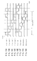
- FIG. 9 shows an example of the arrangement of the stationary electrodes which are arranged deviant by 1 ⁇ 2 phase in the electrostatic actuator shown in FIG. 2 ;
- FIGS. 10A , 10 B, 10 C, 10 D, 10 E, 10 F, 10 G and 10 H are timing charts collectively showing a pattern of the driving voltage for driving the electrostatic actuator having the electrode arrangement shown in FIG. 9 ;
- FIG. 11 is a graph showing the locus of the generated force in the case where the electrostatic actuator shown in FIG. 7 is driven by the driving voltage pattern shown in FIG. 8 ;
- FIG. 12 is a graph showing the locus of the generated force in the case where the electrostatic actuator shown in FIG. 9 is driven by the driving voltage pattern shown in FIG. 10 ;
- FIG. 13 schematically shows the construction of the electrostatic actuator according to the modified embodiment shown in FIG. 2 ;
- FIGS. 14A , 14 B, 14 C, 14 D, 14 E and 14 F are timing charts collectively showing a pattern of the driving voltage for driving the stationary electrodes which are arranged with the phase substantially aligned in the electrostatic actuator shown in FIG. 13 ;
- FIGS. 15A , 15 B, 15 C, 15 D, 15 E and 15 F are timing charts collectively showing a pattern of the driving voltage for driving the stationary electrodes which are arranged deviant by 1 ⁇ 2 phase in the electrostatic actuator shown in FIG. 13 ;
- FIG. 16 is a magnified view schematically showing the operation of the electrostatic actuator according to another embodiment of the present invention.
- FIG. 17 is a magnified view schematically showing the operation of the electrostatic actuator according to another embodiment of the present invention.
- FIG. 18 is a graph showing as a comparative example the locus of the generated force in the case where the electrostatic actuator according to the embodiment shown in FIG. 16 is driven by the ordinary operation;
- FIG. 19 is a graph covering the case where the electrostatic actuator according to the embodiment shown in FIG. 16 is driven by the operation that permits producing a force in the horizontal direction;
- FIGS. 20A , 20 B, 20 C, 20 D and 20 E are timing charts collectively exemplifying a pattern of the driving voltage that permits the electrostatic actuator shown in FIG. 16 to generate a force in the horizontal direction as shown in FIG. 18 ;
- FIG. 21 is a magnified view schematically showing the operation of the electrostatic actuator according to still another embodiment of the present invention.
- FIGS. 22A , 22 B, 22 C, 22 D and 22 E are timing charts collectively showing a pattern of the driving voltage for driving the electrostatic actuator shown in FIG. 21 ;
- FIG. 23 is a graph showing the locus of the force generated in the electrostatic actuator that is driven by the driving voltage pattern shown in FIG. 22 ;
- FIG. 24A is a graph showing the wave form denoting the movement of the movable member included in the electrostatic actuator shown in FIG. 21 ;
- FIG. 24B is a graph showing the wave form denoting the change in the voltage applied between the stationary electrode and the movable member in the electrostatic actuator shown in FIG. 21 ;
- FIG. 25 is a graph showing the relationship between the electrical resistance and the time delay Td in the case where the applied voltage is set at 150V in the electrostatic actuator shown in FIG. 21 ;
- FIG. 26 is a graph showing the relationship between the electrical resistance and the time period TU required for a unit movement in the case where the applied voltage is set at 150V in the electrostatic actuator shown in FIG. 21 ;
- FIG. 27 is a graph showing the relationship between the electrical resistance of the movable member and the time delay Td in the electrostatic actuator shown in FIG. 21 ;
- FIG. 28 is a graph showing the relationship between the electrical resistance of the movable member and the time period TU required for a unit movement in the electrostatic actuator shown in FIG. 21 ;
- FIG. 29 is a block diagram exemplifying a camera system in which is incorporated a circuit for optimizing a pattern of the driving signal for driving the electrostatic actuator according to another embodiment of the present invention.
- FIG. 2 shows an electrostatic actuator according to one embodiment of the present invention, which is called an electrostatic actuator of a both side propelling driving type.
- a movable member 11 that is to be driven is arranged in the space between two stationary members 12 and 13 that face each other.
- the movable member 11 is arranged slidable in the forward direction denoted by an arrow 21 or in the backward direction opposite to the forward direction denoted by the arrow 21 .
- Electrode sections 16 are formed in the movable member 11 .
- stationary electrodes 12 a , 12 b , 12 c and 12 d are arranged to form a group on the stationary member 12 .
- a plurality of groups of these stationary electrodes is consecutively arranged along the arrow 21 on the stationary member 12 .
- stationary electrodes 12 e , 12 f , 12 g and 12 h are arranged to form a group on the stationary member 13 .
- a plurality of groups of these stationary electrodes is also consecutively arranged along the arrow 21 on the stationary member 13 .
- the system in which voltage is applied at a different timing to the four stationary electrodes is called a four electrode system or is simply called a four system.
- letters A, B, C, D, E, F, G and H indicate stationary electrodes 12 a , 12 b , 12 c , 12 d , 13 e , 13 f , 13 g and 13 h , respectively, for convenience' sake in the description.
- these stationary electrodes are referred to in the following description as, for example, stationary electrode A ( 12 a ) or simply as electrode B ( 12 b ) in some cases.
- these stationary electrodes 12 a , 12 b , 12 c , 12 d , 13 e , 13 f , 13 g and 13 h are formed in substantially the same pitch Ph on the stationary members 12 and 13 .
- these stationary electrodes are substantially equal to each other in the width.
- the movable electrodes 16 are formed at a pitch 4 Ph on the movable member 11 in a manner to face the stationary electrodes 12 a , 12 b , 12 c , 12 d and the stationary electrodes 13 e , 13 f , 13 g , 13 h .
- the width L of the movable electrode 16 is set at a level 1.5 to 2.5 times as much as the width W of each of the stationary electrodes 12 a , 12 b , 12 c , 12 d and the stationary electrodes 13 e , 13 f , 13 g , 13 h .
- the stationary electrodes 12 a , 12 b , 12 c , 12 d and the stationary electrodes 13 e , 13 f , 13 g , 13 h are arranged to cover a range over which the movable member 11 is moved, and each of the movable electrodes 16 is positioned to face two adjacent electrodes included in the stationary electrodes 12 a , 12 b , 12 c , 12 d and the stationary electrodes 13 e , 13 f , 13 g , 13 h .
- the stationary electrodes 12 a , 12 b , 12 c , 12 d may be positioned simply to face the stationary electrodes 13 e , 13 f , 13 g , 13 h when the electrostatic actuator is assembled.
- the electrostatic actuator of the present invention shown in FIG. 2 differs from the conventional electrostatic actuator in that the stationary electrodes 12 a , 12 b , 12 c , 12 d need not be aligned with the stationary electrodes 13 e , 13 f , 13 g , 13 h when the electrostatic actuator is assembled.
- the stationary electrodes 12 a , 12 b , 12 c , 12 d and the stationary electrodes 13 e , 13 f , 13 g , 13 h are arranged to achieve an alignment in the phase of the arrangement, it is possible for the phase of the arrangement to be deviated within a range of 1 ⁇ 2 phase or within a range of between 0 and 1 ⁇ 2 phase.
- the stationary electrodes 12 a , 12 b , 12 c , 12 d and the stationary electrodes 13 e , 13 f , 13 g , 13 h are arranged to face each other, the deviation ⁇ P in the phase between the stationary electrodes 12 a , 12 b , 12 c , 12 d of the stationary member 12 and the stationary electrodes 13 e , 13 f , 13 g , 13 h of the stationary member 13 falls within a small range of between 0 and Ph/2 pitch, i.e., 0 ⁇ P ⁇ Ph/2.
- the movable electrode 16 In the electrostatic actuator shown in FIG. 2 , it is possible for the movable electrode 16 to have a positional relationship with the stationary electrodes 12 a , 12 b , 12 c , 12 d as shown in FIG. 3 . If voltage is applied in this case from a voltage source 6 to the stationary electrodes 12 b and 12 c through a switching circuit 5 , an electrostatic force, i.e., the Coulomb force, is generated between the stationary electrodes 12 b , 12 c and the movable electrode 16 , with the result that the movable member 11 is attracted toward the stationary member 12 such that the stationary electrodes 12 b , 12 c are allowed to overlap with the movable electrode 16 .
- an electrostatic force i.e., the Coulomb force
- the switching circuit 5 is switched from the stationary electrodes 12 b , 12 c to the stationary electrodes 13 f , 13 g so as to apply voltage to the stationary electrodes 13 f , 13 g or 13 g , 13 h , the movable member 11 is attracted toward the other stationary member 13 such that the movable electrode 16 is allowed to overlap with the stationary electrodes 13 f , 13 g or 13 g , 13 h .
- the switching circuit 5 when the switching circuit 5 is switched from the stationary electrodes 13 f , 13 g or 13 g , 13 h to the stationary electrodes 12 c , 12 d so as to apply voltage to the stationary electrodes 12 c , 12 d , the movable member 11 is attracted toward the stationary member 12 such that the movable electrode 16 is allowed to overlap with the stationary electrodes 12 c , 12 d . Further, when the switching circuit 5 is switched to apply voltage to electrodes of the other stationary member 13 , the movable member 11 is attracted toward the other stationary member 13 .
- the movable member 11 If voltage, which is successively switched, is applied to the electrodes of the stationary members as described above, the movable member 11 is macroscopically moved forward as denoted by the arrow 21 in FIG. 2 while being vibrated microscopically between the stationary members 12 and 13 . If the order of the voltage application is reversed, the movable member 11 is driven in the backward direction, which is opposite to the direction denoted by the arrow 21 in FIG. 2 .
- Described in the following with reference to FIGS. 3 to 6 is the relationship between the position of the movable electrode 16 and the force generated in the vertical direction and the horizontal direction (moving direction) between the movable electrode 16 and the four system electrodes 12 a , 12 b , 12 c , 12 d formed on the stationary member 12 in respect of the electrostatic actuator shown in FIG. 2 .
- n represents the number of projecting electrodes 16 formed in the movable member 11
- ⁇ represents the dielectric constant between the movable electrode 16 of the movable member 11 and each of the electrodes 12 a , 12 b , 12 c , 12 d formed on the stationary member 12
- M represents the depth distance, i.e., the length in the direction perpendicular to the moving direction of the movable member, in the case where the movable electrode 16 overlaps with some of the stationary electrodes 12 a , 12 b , 12 c , 12 d or represents 0 in the case where there is no overlapping
- S represents the area of the portion where the movable electrode and the stationary electrodes are positioned to face each other
- V represents the voltage applied between the electrodes
- d represents the distance between the electrodes.
- the distance “d” corresponds to the gap between the movable electrode 16 and the stationary electrode shown in FIG. 3 .
- the dielectric constant ⁇ is represented by the value obtained by multiplying the dielectric constant of vacuum by the relative dielectric constant of a certain substance present between the movable member 11 and each of the electrodes 12 a , 12 b , 12 c , 12 d formed on the stationary member 12 .
- the dielectric constant ⁇ 0 of vacuum is 8.85 ⁇ 10 ⁇ 12 [N/m].
- the relative dielectric constant of, for example, the air is about 1
- the relative dielectric constant of polyimide used for insulation of, for example, an electrode is about 3.
- FIG. 3 shows the state that the stationary electrodes 12 b and 12 c are allowed to overlap with the movable electrode 16 .
- FIGS. 4 and 5 shows the state that the stationary electrodes 12 b and 12 c are not allowed at all to overlap with the movable electrode 16 .
- the overlapping depth distance M is changed in accordance with the change from the state shown in FIG. 4 to the state shown in FIG. 3 or from the state shown in FIG. 3 to the state shown in FIG. 5 .
- S in formula (1) given above represents the area of the portion where the movable electrode faces the stationary electrodes, as described above. It should be noted that a single stationary electrode has a width W in the horizontal moving direction of the movable member 11 , and a single movable electrode 16 has a width L in the horizontal moving direction of the movable member 11 .
- the area S is equal to M ⁇ R, where R represents the width (overlapping length of the movable member in the moving direction) of the stationary electrode and the movable electrode positioned to face each other.
- M has a relationship of 0 ⁇ R ⁇ 2 W.
- the formulas (1) and (2) given above are directed to a model covering the case where the thickness direction of the electrode is neglected.
- neglected are the influence in the depth direction of the movable member 11 , i.e., the tapered side surfaces of the protruding movable electrode 16 shown in FIG. 2 , and the influences among the electrodes 12 a , 12 b , 12 c , 12 d formed on the stationary member 12 .
- the definition of the coordinate (X-Z) in FIGS. 3 to 6 will now be described.
- the center point P ref of the protruding electrode 16 of the movable member 11 is used as a reference point.
- formulas (1) and (2) given previously denote the magnitude alone of the generated force and do not denote the acting direction of the generated force.
- Formulas (1) and (2) given previously indicate that, if the displacement of the movable member 11 is not smaller than ⁇ L as shown in FIG. 4 , the protruding electrode 16 of the movable member 11 and the stationary electrode 12 b do not face each other even if these electrodes 16 and 12 b are positioned in parallel. As a result, an overlapping parallel plate portion is not included in the arrangement of the movable member 11 and the stationary member 12 . It follows that each of S in formula (1) and M in formula (2) becomes 0 and, thus, each of the generated force Fz in the vertical direction and the generated force Fy in the horizontal direction (moving direction) also becomes zero.
- the generated force Fy in the horizontal direction (moving direction) is rendered constant regardless of the position of the movable member 11 .
- the component R noted above i.e., the overlapping amount between the protruding electrode 16 of the movable member 11 and the stationary electrode
- M in formula (2) assumes a binary value of zero or a constant value in respect of the overlapping.
- the direction of the generated force is on the plus side, i.e., the direction of +X.
- the generated force Fz in the vertical direction is increased with increase in the overlapping amount in the horizontal direction between the protruding electrode 16 of the movable member 11 and the stationary electrode, i.e., with increase in R.
- the overlapping amount is rendered maximum when the displacement of the movable member 11 is exactly zero and, thus, the generated force Fz in the vertical direction is rendered maximum.
- FIG. 3 shows the state that the displacement of the movable member 11 is zero.
- the generated force Fy in the horizontal direction (moving direction) is constant and the direction of the force is reversed to minus regardless of the position of the movable member 11 in also the case where the displacement of the movable member 11 falls within a range of between 0 and +L.
- the generated force Fz in the vertical direction is decreased with decrease in the overlapping amount, i.e., decrease in R. If the displacement of the movable member 11 exceeds L, there is no overlapping amount and, thus, each of the generated force Fz in the vertical direction and the generated force in the horizontal direction (moving direction) is rendered zero, as described previously.
- FIG. 5 shows the state that the displacement of the movable member 11 is +L.
- the generated force Fy in the horizontal direction is changed to depict a rectangular wave form such that the generated force Fy is zero if the displacement of the movable member 11 is smaller than ⁇ L, the generated force Fy is changed to a plus constant value if the displacement of the movable member 11 falls within a range of between ⁇ L and 0, the generated force Fy is changed to a minus constant value if the displacement of the movable member 11 falls within a range of between 0 and +L, and the generated force Fy is changed again to zero if the displacement of the movable member 11 is larger than +L.
- the generated force is not instantly changed from zero to a constant value, but is changed gradually. The gradual change is based on the influences given by the component in the thickness direction of each electrode, which is neglected in each of formulas (1) and (2) given previously.
- the generated force in the gradually changed portion greatly affects the driving of the actuator and, thus, cannot be neglected in practice.
- FIG. 6 is a graph showing the changes obtained by a finite-element method in the generated force Fz and the generated force Fy in respect of the positional relationship between the protruding electrode 16 of the movable member 11 and each of the electrodes 12 a , 12 b , 12 c , 12 d formed on the stationary member 12 .
- the positional relationship is as in the coordinate system defined above.
- Curve I in FIG. 6 which is plotted by rectangular marks, corresponds to the generated force Fz in the vertical direction, and curve II plotted by circular marks corresponds to the generated force Fy in the horizontal direction (moving direction).
- the force (unit of N) is plotted on the ordinate, and the positional relationship between the movable electrode 16 of the movable member 11 and the stationary electrodes B ( 12 b ), C ( 12 c ) formed on the stationary member 2 is plotted on the abscissa in terms of the deviation ( ⁇ m).
- the dimension is determined on the assumption that the electrostatic actuator is used in a mobile device such as a portable telephone as a camera module, as described herein later.
- the gap d is 7.8 ⁇ m
- the width w of the stationary electrode is 12 ⁇ m
- the pitch Ph is 16 ⁇ m
- the width L of the protruding electrode 16 formed in the movable member 11 is 28 ⁇ m
- the number of movable electrodes 16 is 94.
- the generated force Fy in the horizontal direction (moving direction) is gradually changed immediately before and after the protruding movable electrode 16 of the movable member 11 overlaps with and is moved away from the stationary electrode B ( 12 b ), which clearly differs from the model given by formulas (1) and (2) in which the thickness is neglected.
- the generated force in the horizontal direction (moving direction) is replaced by a sine wave form joining the 0-point and the maximum value for the sake of brevity.
- the voltage V applied to the stationary electrodes 12 b , 12 c is a value calculated on the basis of 100V.
- a switching mode setting circuit 7 for designating one of a first voltage pattern VP 1 and a second voltage pattern VP 2 , which are described herein later, is arranged as shown in FIG. 2 in view of the characteristics shown in FIG.
- the positions of the stationary electrodes 12 a , 12 b , 12 c , 12 d and the stationary electrodes 13 e , 13 f , 13 g , 13 h are substantially aligned in assembling the electrostatic actuator as denoted by a broken line 50 shown in FIG. 7 and, thus, the deviation ⁇ P between the corresponding electrodes, e.g., between the stationary electrode A ( 12 a ) and the stationary electrode E ( 12 e ), is substantially zero or is sufficiently small, i.e., 0 ⁇
- the deviation ⁇ P between the corresponding electrodes is substantially equal to Ph/2 or is sufficiently close to Ph/2, i.e., Ph/2 ⁇
- FIG. 7 shows the positional relationship that permits the stationary electrodes 12 a , 12 b , 12 c , 12 d to overlap with the stationary electrodes 13 e , 13 f , 13 g , 13 h without giving rise to a deviation.
- the phase difference between the stationary electrodes 12 a , 12 b , 12 c , 12 d and the stationary electrodes 13 e , 13 f , 13 g , 13 h is substantially zero.
- FIG. 9 shows the positional relationship that permits producing the largest phase difference between the stationary electrodes 12 a , 12 b , 12 c , 12 d and the stationary electrodes 13 e , 13 f , 13 g , 13 h .
- the phase difference relating to the arrangement of the stationary electrodes 13 e , 13 f , 13 g , 13 h relative to the arrangement of the stationary electrodes 12 a , 12 b , 12 c , 12 d is 1 ⁇ 2 and the deviation ⁇ P thereof is Ph/2.
- the movable member 11 is macroscopically driven forward to the right on the paper while being microscopically vibrated in the up-down direction. As apparent from the description given above, the movable member 11 is driven backward to the left on the paper, if the order of the voltage pattern applied to the stationary electrodes 12 a , 12 b , 12 c , 12 d , 13 e , 13 f , 13 g , 13 h is reversed.
- the driving operation of the movable member 11 is as shown in the graph of FIG. 11 .
- the position of the movable member 11 in the horizontal direction (moving direction) relative to the stationary member 12 is plotted on the abscissa.
- the generated force in the moving direction when the movable member 11 is positioned in each of the relative positions is plotted on the ordinate.
- the description of AB phase, DA phase, etc. along the abscissa denotes that voltage is applied to the electrodes corresponding to the symbols shown in FIG. 7 .
- the AB phase it is denoted that voltage as shown in FIG. 8 is applied to the stationary electrodes A ( 12 a ) and B ( 12 b ).
- the definition of the coordinate will now be described.
- the center between the stationary electrodes A ( 12 a ) and B ( 12 b ) is used as the origin 0, and left side on the paper denotes minus and the right side on the paper denotes plus, as shown in FIG. 3 .
- the center point P ref of the protruding electrode 16 is used as a reference in the movable member 11 .
- the position of the movable member 11 relative to the stationary member 12 represents the displacement from the reference point P ref and the origin 0, and the plus-minus relationship is as described above.
- the voltage application is switched from the AB phase (voltage application to the stationary electrodes A ( 12 a ) and B ( 12 b )) to the FG phase (voltage application to the stationary electrodes F ( 12 f ) and G ( 13 g )).
- the generated force Fy in the horizontal direction has a sine wave form having the maximum value at the position of ⁇ 16 ⁇ m. It should be noted that the generated force is zero in each of the position of ⁇ 32 ⁇ m and the position of 0 ⁇ m. However, the position of ⁇ 32 ⁇ m differs from the position of 0 ⁇ m in the significance, though the generated force is zero in each of these positions.
- the position of ⁇ 32 ⁇ m denotes the state that the protruding electrode 16 of the movable member 11 is positioned to face exactly the stationary electrodes C ( 12 c ) and D ( 13 d ). If voltage is applied to the stationary electrodes A ( 12 a ) and B ( 12 b ) under this state, the protruding electrode 16 of the movable member 11 receives a generated force corresponding to the deviation of ⁇ 32 ⁇ m shown in FIG. 65 on the plus side from the AB phase (stationary electrodes A ( 12 a ) and B ( 12 b )) positioned forward in the moving direction.
- the protruding electrode 16 of the movable member 11 receives a generated force corresponding to the deviation of +32 ⁇ m shown in FIG. 6 on the minus side from the AB phase positioned backward in the moving direction. It follows that the generated force on the plus side is offset with the generated force on the minus side so as to permit the generated force to be zero.
- the position of 0 ⁇ m denotes the state that the protruding electrode 16 of the movable member 11 is positioned to face the stationary electrodes A ( 12 a ) and B ( 12 b ). If voltage is applied to the AB phase under this state, the generated force corresponds to the case where the deviation shown in FIG. 6 is 0 ⁇ m, and the generated force in the horizontal direction is zero.
- the generated force in the case of applying voltage to the stationary electrodes F ( 12 f ) and G ( 13 g ) is represented by a sine wave having the maximum value at the origin 0 .
- the switching of the electrodes to which voltage is applied from the stationary electrodes A ( 12 a ) and B ( 12 b ) to the stationary electrodes F ( 12 f ) and G ( 13 g ) denotes the change in the generated force Fy along the solid line leading from the AB phase to the FG phase plotted on the abscissa of the graph shown in FIG. 11 . It is seen from FIG. 11 that, if the electrodes are arranged as shown in FIG.
- the minimal values of the generated force are the same and are small in fluctuation.
- the distance d which corresponds to the gap shown in FIG.
- FIG. 9 The operation of the electrostatic actuator having the electrode arrangement in which the phase difference is 1 ⁇ 2 will now be described with reference to FIG. 9 .
- voltage is applied first to the stationary electrodes A ( 12 a ) and B ( 12 b ) formed on the stationary member 12 , as shown in FIGS. 10A and 10B .
- the attractive force 14 is exerted on the movable member 11 so as to drive the movable member 11 in a manner to permit the protruding electrode 16 of the movable member 11 to overlap with the stationary electrodes A ( 12 a ) and B ( 12 b ), as described previously.
- the movable member 11 is driven backward to the left on the paper, if the order of the voltage pattern applied to the stationary electrodes 12 a , 12 b , 12 c , 12 d , 13 e , 13 f , 13 g , 13 h is reversed.
- FIG. 12 shows the driving operation of the movable member 11 described previously with the attentions paid to the generated force Fy in the individual electrode sections described previously.
- the second voltage pattern VP 2 shown in FIG. 10 is applied to the stationary electrodes 12 a , 12 b , 12 c , 12 d , 13 e , 13 f , 13 g , 13 h , the phase difference between the movable member 11 and each of the stationary electrodes 12 a , 12 b , 12 c , 12 d , 13 e , 13 f , 13 g , 13 h causes the generated force to become as shown in FIG. 12 .
- the semi-arc denoting the generated force of the EF phase is deviated by 8 ⁇ m to the left on the paper because the stationary electrodes E ( 12 e ) and F ( 12 f ) are deviated from the stationary electrodes A ( 12 a ) and B ( 12 b ) by half the electrode pitch of, for example, 16 ⁇ m, i.e., deviated by 8 ⁇ m.
- the portion of the force generated in the movable member 11 is denoted by a solid line, the situation is as shown in FIG. 12 . If compared with the graph shown in FIG. 11 , it can be understood that the change in the generated force (force gap) is large and that the minimum value is lowered. However, the force Fy is kept generated in the moving direction.
- the phase difference relating to the arrangement of the stationary members 12 and 13 falls within a range of between 0 (minimum) and the half phase (maximum). Therefore, if the first voltage pattern PV 1 and the second voltage pattern PV 2 are generated from the switching circuit 5 , the electrostatic actuator is driven by any of the voltage patterns. To be more specific, the force Fy is kept generated in the moving direction so as to drive the movable member 11 even if the positions of the stationary members 12 and 13 are not aligned. It follows that it is possible to judge which of the driving voltage pattern VP 1 or VP 2 to apply is appropriate by applying first the first and second driving voltage patterns VP 1 and VP 2 to the stationary electrodes at a different timing.
- a position sensor 8 for detecting the movement of the movable member 11 in the electrostatic actuator as shown in FIG. 2 it is possible to mount a position sensor 8 for detecting the movement of the movable member 11 in the electrostatic actuator as shown in FIG. 2 , to detect which of the first and second driving voltage patterns VP 1 and VP 2 served to drive the movable member 11 by the position sensor 8 , and to allow the switching mode setting circuit 7 to designate one of the first and second driving voltage patterns in response to the output from the position sensor 8 .
- the electrostatic actuator shown in FIG. 2 is of a four system type in which voltage is applied to four stationary electrodes at a different timing.
- a first voltage pattern VP 1 as shown in FIGS. 14A to 14F is applied to the stationary electrodes 12 a , 12 b , 12 c and the stationary electrodes 13 e , 13 f , 13 g in the case where the stationary electrodes 12 a , 12 b , 12 c and the stationary electrodes 13 e , 13 f , 13 g are arranged with the phase difference of substantially zero. If voltage is applied to the stationary electrodes A ( 12 a ) and B ( 12 b ) formed on the stationary member 12 as shown in FIGS.
- the attractive force 14 is exerted on the movable member 11 so as to drive the movable member 11 in a manner to permit the protruding electrode 16 of the movable member 11 to overlap with the stationary electrodes A ( 12 a ) and B ( 12 b ).
- voltage is applied to the stationary electrodes F ( 12 f ) and G 13 f , which are positioned away from the stationary electrodes A ( 12 a ) and B ( 12 b ) by one pitch Ph in the moving direction, not to the stationary electrodes E ( 12 e ) and F ( 12 f ), which are positioned to face exactly the stationary electrodes A ( 12 a ) and B ( 12 b ), as shown in FIGS.
- FIGS. 14C and 14A voltage is applied to the stationary electrodes C ( 12 c ) and A ( 12 a ) formed on the stationary member 12 , as shown in FIGS. 14C and 14A , followed by applying voltage to the stationary electrodes E ( 12 e ) and F ( 12 f ), as shown in FIG. 14D and FIG. 8E . If the voltage application pattern of one cycle described above is repeated, the movable member 11 is macroscopically driven forward to the right on the paper while being microscopically vibrated in the up-down direction.
- the movable member 11 is driven backward to the left on the paper, if the order of the voltage pattern applied to the stationary electrodes 12 a , 12 b , 12 c , 13 e , 13 f , 13 g is reversed.
- the second voltage pattern VP 2 as shown in FIGS. 15A to 15F is applied to the stationary electrodes 12 a , 12 b , 12 c and the stationary electrodes 13 e , 13 f , 13 g in the case where the stationary electrodes 12 a , 12 b , 12 c and the stationary electrodes 13 e , 13 f , 13 g are arranged with the phase difference of about 1 ⁇ 2. If voltage is applied to the stationary electrodes A ( 12 a ) and B ( 12 b ) formed on the stationary member 12 as shown in FIGS.
- the attractive force 14 is exerted on the movable member 11 so as to drive the movable member 11 in a manner to permit the protruding electrode 16 of the movable member 11 to overlap with the stationary electrodes A ( 12 a ) and B ( 12 b ).
- voltage is applied to the stationary electrodes E ( 12 e ) and F ( 12 f ), which are positioned away from the stationary electrodes A ( 12 a ) and B ( 12 b ) by a half pitch Ph/2 in the moving direction, as shown in FIGS. 15D and 15E .
- the attractive force 15 is similarly exerted on the movable member 11 so as to drive the movable member 11 in a manner to permit the protruding electrode 16 of the movable member 11 to overlap with the stationary electrodes E ( 12 e ) and F ( 12 f ).
- voltage is applied to the stationary electrodes B ( 12 b ) and C ( 12 c ) formed on the stationary member 12 , as shown in FIGS. 15B and 15C , followed by applying voltage to the stationary electrodes F ( 12 f ) and G ( 13 g ), as shown in FIGS. 15E and 15F .
- FIGS. 15C and 15A voltage is applied to the stationary electrodes C ( 12 c ) and A ( 12 a ) formed on the stationary member 12 , as shown in FIGS. 15C and 15A , followed by applying voltage to the stationary electrodes C ( 13 g ) and A 13 a , as shown in FIGS. 15F and FIG. 15A . If the voltage application pattern of one cycle described above is repeated, the movable member 11 is macroscopically driven forward to the right on the paper while being microscopically vibrated in the up-down direction.
- the movable member 11 is driven backward to the left on the paper, if the order of the voltage pattern applied to the stationary electrodes 12 a , 12 b , 12 c , 13 e , 13 f , 13 g is reversed.
- the electrostatic actuator As apparent from the description given above relating to FIG. 13 , it is possible to apply the technical idea of the present invention to the electrostatic actuator according to the embodiment of the present invention as far as the electrostatic actuator is of the type of three system or more, in which voltage is applied to at least three stationary electrodes at a different timing.
- FIGS. 16 to 20 An electrostatic actuator according to another embodiment of the present invention will now be described with reference to FIGS. 16 to 20 .
- FIG. 16 shows an electrostatic actuator called a one side propelling driving type. Unlike the both side propelling driving type electrostatic actuator, which is shown in FIG. 2 , the electrostatic actuator shown in FIG. 16 comprises four stationary electrodes 12 a , 12 b , 12 c , 12 d , to which voltage is applied at a different timing and which are arranged to form a group on the stationary member 12 . A plurality of these groups are successively formed on the stationary member 12 . On the other hand, a single stationary electrode E ( 12 e ) is formed on the other stationary member 13 .
- the force Fy is not generated in the moving direction in attracting the movable member 11 by applying voltage to the stationary electrode E ( 12 e ). It follows that the operation tends to be rendered unstable depending on the posture of the electrostatic actuator. On the other hand, the force Fy can be generated in the moving direction in attracting the movable member 11 toward the stationary electrode E ( 12 e ) by applying an auxiliary voltage to some of the stationary electrodes 12 a , 12 b , 12 c , 12 d formed on the stationary member 12 in accordance with the movement of the movable member 11 .
- FIG. 18 shows a comparative example serving to facilitate the understanding of this embodiment of the present invention. In this fashion, it is possible to keep the force Fy generated by applying an auxiliary voltage to any of the stationary electrodes 12 a , 12 b , 12 c , 12 d in accordance with movement of the movable member in attracting the movable member 11 toward the stationary electrode E ( 12 e ).
- a voltage pattern shown in FIGS. 20A to 20E is applied to the stationary electrodes 12 a , 12 b , 12 c , 12 d and the stationary electrode 13 e .
- voltage is applied to the stationary electrodes A ( 12 a ) and B ( 12 b ) as shown in FIG. 20A so as to permit the movable electrode 16 to be attracted toward the stationary electrodes A ( 12 a ) and B ( 12 b ). If the voltage application is switched from the stationary electrodes A ( 12 a ) and B ( 12 b ) to the stationary electrode 13 e at the timing shown in FIG. 20E , the movable electrode 16 is attracted toward the stationary electrode 13 e .
- the movable electrode 16 is slightly moved toward the stationary electrodes B ( 12 b ) and C ( 12 c ) as shown in FIG. 19 as well as in FIG. 18 directed to a comparative example. Also, if the voltage application is switched from the stationary electrodes B ( 12 b ) and C ( 12 c ) to the stationary electrode 13 e at a certain timing, and if the auxiliary voltage Vs is temporarily applied to the stationary electrode C ( 12 c ) as shown in FIG. 20C , a driving force slightly moving toward the stationary electrode C ( 12 c ) as shown in FIG.
- t in each of FIGS. 18 and 19 represents the timing at which voltage is applied to each of the stationary electrodes 12 a , 12 b , 12 c and 12 d.
- FIG. 21 shows an electrostatic actuator of one side propelling driving type as in FIG. 16 .
- force is not generated in the moving direction when the movable member 11 is attracted toward the stationary electrode E ( 12 e ), with the result that the operation of the electrostatic actuator tends to be rendered unstable depending on the posture of the electrostatic actuator.
- changed in this embodiment is the ratio of the period during which voltage of a high level is applied to the stationary electrode E ( 12 e ) so as to permit the movable member 11 to be attracted to the stationary electrode E ( 12 e ) to the period during which voltage of a high level is applied to the stationary electrodes 12 a , 12 b , 12 c , 12 d so as to permit the movable member 11 to be attracted to the stationary electrode 12 a , 12 b , 12 c , 12 d , as shown in FIGS. 22A to 22E .
- the force Fy generated in the movable member 11 in the moving direction is schematically shown in FIG. 23 . As shown in FIGS.
- the ratio of the period during which voltage of a high level is applied to each of the stationary electrodes 12 a , 12 b , 12 c , 12 d to the period during which voltage of a high level is applied to the stationary electrode E ( 12 e ) is set at 2:1.
- the period during which voltage of a high level is applied to the stationary electrode E ( 12 e ) is made shorter than the period during which voltage of a high level is applied to each of the stationary electrodes 12 a , 12 b , 12 c , 12 d , it is possible to shorten the period during which the operation of the electrostatic actuator is rendered unstable under the influences given by the weight (gravitational force) of the electrostatic actuator itself accompanying the change in the posture of the electrostatic actuator itself. As a result, it is possible to suppress the unstable operation of the electrostatic actuator.
- the ratio of the period during which voltage of a high level is applied to each of the stationary electrodes 12 a , 12 b , 12 c , 12 d to the period during which voltage of a high level is applied to the stationary electrode E ( 12 e ) is set at 2:1 in the embodiment described above.
- the reason for the particular ratio is as given below.
- the standard moving speed at which the movable member 11 is moved by the operation of the electrostatic actuator is assumed to be 1.0 mm/s. In this movement, the period of the pattern shown in FIGS. 22A to 22E (one cycle) is set at 1 ms.
- the time required for the movable member 11 of the electrostatic actuator, which is attracted by the lower electrode 13 e , to be moved from the upper electrodes 12 a , 12 b , 12 c , 12 d to reach the lower electrode 13 e is calculated by formula (4) given below, which is based on formula (3) given below.
- formula (3) represents the force F generated in the lower electrode 13 e so as to attract the movable member 11 .
- Fz n ⁇ ⁇ ( SV 2 /2 d 2 ) (1)
- F ⁇ ( SV 2 /2 d 2 ) (3)
- ⁇ represents the dielectric constant, which is 8.85 ⁇ 10 ⁇ 12 F/m under vacuum
- S represents the electrode area of the lower electrode 13 e
- V represents the voltage applied to the lower electrode 13 e
- d represents the distance between the movable member 11 and the lower electrode 13 e.
- m represents the sum of the mass of the movable member 11 and the mass of the load moved together with the movable member 11 , e.g., the weight of the lens.
- H represents the moving distance of the movable member 11 , which corresponds to the amplitude of the vertical vibration.
- the effective distance of the gap between the upper and lower stationary electrodes (or the moving distance of the movable member in practice) is decreased so as to improve the generated force for moving the movable member 11 . It follows that it is necessary to make the time for attracting the movable member 11 to the stationary electrode 13 e arranged in the lower portion of the electrostatic actuator shorter than the time for moving the movable member 11 toward the stationary electrodes 12 a , 12 b , 12 d , 12 d .
- the time if calculated by the formula given above, is about 0.2 to 0.3 ms.
- the gap between the upper and lower electrodes, etc. are changed depending on, for example, the manufacturing accuracy of the movable member 11 , with the result that the moving time is also changed.
- the motion of the movable member 11 in the vertical direction is affected by the viscosity of the air present in the gap between the movable member 11 and the stationary electrodes 12 a , 12 b , 12 c , 12 d or between the movable member 11 and the stationary electrode 13 e .
- Counterforce proportional to the velocity of the movable member 11 is basically exerted on the movable member 11 . It should be noted in this connection that the magnitude and direction of the counterforce are greatly changed depending on the air passageway formed, which is determined by the posture of the movable member 11 relative to the stationary electrodes 12 a , 12 b , 12 c , 12 d or the stationary electrode 13 e .
- the moving time noted above is about 0.3 ms to 0.8 ms.
- the duty ratio d is not limited to 0.5. It is possible to set the duty ratio d based on the period of the driving pattern used such that the time required for the movable member 11 to be attracted by the stationary electrode 13 e formed in the lower portion falls within a range of between 0.3 ms and 0.8 ms as described above.
- the duty ratio d can be set to fall within a range of between 0.3 and 0.8, i.e., 0.3 ⁇ d ⁇ 0.8.
- the ratio of the period during which voltage of a high level is applied to each of the stationary electrodes 12 a , 12 b , 12 c , 12 d to the period during which voltage of a high level is applied to the stationary electrode E ( 12 e ) is set at 2:1.
- the period ratio noted above is not limited to 2:1 as described previously.
- the movable member 11 is slightly driven by application of voltage of a high level to each of the stationary electrodes 12 a , 12 b , 12 c , 12 d in the case where the movable electrode 16 of the movable member 11 has the ground potential.
- the movable member 11 is slightly driven by application of voltage of a low level to each of the stationary electrodes 12 a , 12 b , 12 c , 12 d in the case where the potential of the movable electrode 16 of the movable member 11 is maintained at a high level. It follows that, in this embodiment, the situation is apparently changed to the condition that the period during which voltage of a low level is applied to the stationary electrode E ( 12 e ) is shorter than the period during which voltage of a low level is applied to each of the stationary electrodes 12 a , 12 b , 12 c , 12 d.
- the time for the movable member 11 to be attracted toward the stationary electrode E ( 12 e ) arranged in the lower portion of the electrostatic actuator is set shorter than the time for the movable member 11 to be attracted toward the stationary electrodes 12 a , 12 b , 12 c , 12 d .
- FIG. 24A shows the moving distance of the movable member 11 and the time required for the movement when the movable member 11 is vibrated in the vertical direction.
- FIG. 24B shows the change in the potential difference between the stationary member 13 and the movable member 11 , which is generated by application of voltage to the stationary electrode 13 e on the lower side. If a driving voltage is imparted to the stationary electrode 13 e at a certain time point ta under the state that the movable member 11 is attracted toward the stationary electrodes 12 a , 12 b , 12 c , 12 d as shown in FIG.
- the movable member 11 begins to be moved toward the stationary member 13 at time point tb, a certain time delay Td residing between the time point ta and the time point tb, as shown in FIG. 24A . If the potential difference between the stationary member 13 and the movable member 11 is increased as shown in FIG. 24B , the movable member 11 is moved toward the stationary member 13 at a moving speed Vm. At time point tc a certain moving time TM after the time point tb, the movable member 11 is positioned on the side of the stationary member 13 and retained as it is.
- the potential difference between the stationary member 13 and the movable member 11 is lowered and, at the same time, the movable member 11 begins to be moved toward the stationary electrodes 12 a , 12 b , 12 c , 12 d at time point td, as shown in FIG. 24B .
- the moving speed Vm is obtained by dividing the moving distance H by the moving time TM.
- time period TU required for the unit movement of the movable member 11 (movement of the movable member with the moving distance H providing a unit).
- the movable member 11 can be kept in contact with the teeth-like stationary electrodes 12 a , 12 b , 12 c , 12 d in attracting the movable member 11 to the stationary electrode 13 e by shortening the attracting time corresponding to the moving time TM.
- a greater driving force in the horizontal direction is imparted to the movable member 11 .
- the driving force in the horizontal direction is scarcely generated in the movable member 11 , and the movable member is simply directed toward the stationary electrode 13 e by the driving force in the vertical direction.
- the attracting time toward the lower stationary electrode 13 e which corresponds to the moving time TM, to be shorter than the time required for the vibration of the movable member in the vertical direction, i.e., the time period TU required for the unit movement, and longer than the so-called “delay time Td” between the time point when a driving pulse signal is given to the lower stationary electrode 13 e so as to permit the instruction value of the driving pulse signal to begin to change the voltage and the time point when the movable member 11 gives reaction to the change in the voltage.
- the time TM for the movable member to be attracted by the lower stationary electrode 13 e to satisfy the formula “time delay Td ⁇ attracting time TM by the lower stationary electrode ⁇ time period TU required for the unit movement”.
- the delay time Td and the time period TU required for the unit movement are changed depending on the electrical conductance of the movable member.
- the delay time Td and the time period TU required for the unit movement are changed depending on the electrical resistivity of the material used for forming the movable member.
- FIG. 25 is a graph showing the relationship between the electrical resistivity and the time delay Td in the voltage application of 150V.
- FIG. 26 is a graph showing the relationship between the electrical resistivity and the time period TU required for the unit movement in the voltage application of 150V.
- the measurement was applied to two points for each of the movable member formed of a titanium material having an electrical resistance of 0.5 ⁇ and the movable member formed of a resin material (trade name of Pochicon) having an electrical resistance of 250 ⁇ under the voltage application of each of 120V, 150V and 170V , and the values between the two measured points were obtained by the interpolation.
- the time delay Td and the time period TU required for the unit movement during the upward movement differ from those during the downward movement. This is because the time delay Td and the time period TU required for the unit movement are affected by the gravity during the upward movement.
- the time delay Td and the time period TU required for the unit movement under a certain voltage application e.g., when the applied voltage is set at 150V as shown in FIGS. 27 and 28 .
- the electrical resistance of the titanium material was about 0.5 ⁇ . This value is changed depending on the shape of the movable member 11 . For example, the electrical resistance of the movable member 11 is naturally increased if the volume of the movable member 11 is increased.
- the time delay Td of the movable member 11 was about 0.6 ms during the upward movement and was about 0.4 ms during the downward movement of the movable member 11 .
- the time period TU required for the unit movement was about 1.7 ms during the upward movement and was about 1.2 ms during the downward movement of the movable member 11 , as shown in FIG. 27 . Therefore, in order to drive the movable member 11 such that the movable member 11 is not brought into contact with the lower stationary electrode 13 e and as if the movable member 11 is attracted to the teeth-shaped stationary electrodes 12 a , 12 b , 12 c , 12 d regardless of the posture of the electrostatic actuator, it is necessary make the attracting time TM of the lower stationary electrode 13 e longer than 0.6 ms and shorter than 1.2 ms, i.e., 0.6 ms ⁇ Tm ⁇ 1.2 ms.
- the time delay Td during the upward movement which is about 0.6 ms, to be shorter than the time required for the unit movement during the downward movement, which is about 1.2 ms. If this condition is not satisfied, it is difficult to obtain a sufficient effect unless the time for applying voltage to the lower stationary electrode is changed depending on the posture of electrostatic actuator. Where the applied voltage is changed, and where the material (electrical resistance) of the material used for forming the movable member is changed, it is possible to determine the time for applying voltage to the lower stationary electrode by the procedure similar to that described above.
- the time delay Td and the time period TU required for the unit movement are changed under the influences given by the resistance value depending on the change in the size of the movable element 11 (where the resistivity is the same, the resistance value is increased with increase in the volume) and the weight of the load. Therefore, in manufacturing a movable member and determining the time for applying voltage to the lower stationary electrode, it is necessary to measure first the applied voltage, the electrical resistance, the time delay Td and the time period TU required for the unit movement referred to above and, then, to determine the time for applying voltage to the lower stationary electrode based on the results of the measurement.
- a plurality of driving patterns are prepared in advance, and the driving pattern adapted for the arrangement of the upper and lower stationary electrodes is selected and applied.
- the driving pattern adapted for the arrangement of the upper and lower stationary electrodes is selected and applied.
- the system for selecting the appropriate driving pattern will now be described with reference to FIG. 29 .
- a reference numeral 20 shown in FIG. 29 represents the electrostatic actuator according to the embodiment described above.
- An objective lens system 21 is arranged in the void portion of the movable member 11 included in the electrostatic actuator 20 , and the driving circuit 22 for driving the movable member 10 as described previously is connected to the electrostatic actuator 20 .
- the electrostatic actuator 20 is housed as a camera module in a still or movie camera 24 .
- the objective lens system 21 is arranged to face an object 23 , and a pickup element 26 (CCD or CMOS) is fixed within the electrostatic actuator 20 or within the camera 24 .
- the objective lens system 21 and the pickup element 26 are arranged to permit the image of the object photographed by the objective lens system 21 to be formed on the pickup element 26 .
- a pixel signal is supplied from the pickup element 26 to a video processing circuit 27 , e.g., a video processing IC, with the result that the pixel signal is processed so as to be converted into a video signal.
- the video signal is supplied from the video processing circuit 27 to the camera or a monitor 30 arranged outside the camera, with the result that the image of the object is displayed on the monitor 30 .
- a drive processing circuit 28 for selecting the driving pattern is connected to the video processing circuit 27 , e.g., the video processing IC, and the brightness signal contained in the video signal or a brightness information (analog or digital brightness information) is supplied to the drive processing circuit 28 .
- the drive processing circuit 28 is connected to the measuring device 29 arranged outside the camera 24 as shown in FIG. 29 and the driving signal pattern is selected by the principle given below.
- the object 23 is arranged a predetermined distance L forward of the camera, and a certain driving pattern is given from the driving circuit 22 to the electrostatic actuator 20 .
- the pickup element 26 is driven so as to permit the video processing circuit 27 to give a brightness value information to the drive processing circuit 28 .
- the brightness value information is monitored by the measuring device 29 .
- the largest value can be obtained when the camera is focused on the object 23 . Therefore, the largest brightness value can be measured when the movable member 11 is allowed to be moved to permit the camera to be focused on the object by monitoring the brightness value.
- the movable member 11 within the electrostatic actuator 20 is moved so as to permit the objective lens system 21 to make a back and forth reciprocating movement a plurality of times within the electrostatic actuator 20 . It follows that the brightness value, in which the peak value is caused to appear periodically by the reciprocating movement of the objective lens 21 , is displayed on a display section 29 A within the measuring device 29 shown in FIG. 29 . To be more specific, the objective lens 21 is moved and, in addition, when the objective lens 21 passes through the same position during the reciprocating movement, the peak value is displayed periodically on the display section 29 A within the measuring device 29 .
- the driving circuit 28 supplies a lock signal to the driving circuit 22 such that the driving pattern is kept supplied to the electrostatic actuator 20 on the basis that an appropriate driving pattern is supplied from the driving circuit 22 to the electrostatic actuator 20 .
- the driving patterns generated from the driving circuit 22 are controlled so as to be defined to one of these driving patterns.
- the drive processing circuit 28 judges that the driving pattern is not appropriate so as to control the driving circuit 22 in a manner to allow the driving circuit 22 to impart another driving pattern to the electrostatic actuator 20 on the basis that the movable member 11 is not moved or the movable member 11 is not driven by an appropriate driving pattern.
- the movable member 11 is moved appropriately by measuring the device having the electrostatic actuator incorporated therein even if a sensor for detecting the movement of the movable member is not arranged in the electrostatic actuator, or even if it is not visually confirmed that the movable member 11 is moved appropriately within the electrostatic actuator 20 .
Applications Claiming Priority (2)
| Application Number | Priority Date | Filing Date | Title |
|---|---|---|---|
| JP2001-355098 | 2001-11-20 | ||
| JP2001355098A JP3529761B2 (ja) | 2001-11-20 | 2001-11-20 | 静電アクチュエータ及びその駆動方法 |
Publications (2)
| Publication Number | Publication Date |
|---|---|
| US20050253481A1 US20050253481A1 (en) | 2005-11-17 |
| US7166951B2 true US7166951B2 (en) | 2007-01-23 |
Family
ID=19166852
Family Applications (1)
| Application Number | Title | Priority Date | Filing Date |
|---|---|---|---|
| US10/299,662 Expired - Fee Related US7166951B2 (en) | 2001-11-20 | 2002-11-20 | Electrostatic actuator and method of driving the same |
Country Status (5)
| Country | Link |
|---|---|
| US (1) | US7166951B2 (ja) |
| EP (1) | EP1317054A1 (ja) |
| JP (1) | JP3529761B2 (ja) |
| KR (1) | KR100512823B1 (ja) |
| CN (2) | CN1237694C (ja) |
Cited By (4)
| Publication number | Priority date | Publication date | Assignee | Title |
|---|---|---|---|---|
| US20080218626A1 (en) * | 2002-09-30 | 2008-09-11 | Akihiro Koga | Camera unit for driving lenses and method of manufacturing the same |
| US20100072855A1 (en) * | 2008-09-25 | 2010-03-25 | Sanyo Electric Co., Ltd. | Electrostatic induction power generator |
| US10840826B2 (en) * | 2016-09-29 | 2020-11-17 | Citizen Watch Co., Ltd. | Electromechanical transducer |
| US11303225B2 (en) * | 2017-03-22 | 2022-04-12 | Citizen Watch Co., Ltd. | Electrostatic motor |
Families Citing this family (13)
| Publication number | Priority date | Publication date | Assignee | Title |
|---|---|---|---|---|
| JP3529761B2 (ja) * | 2001-11-20 | 2004-05-24 | 株式会社東芝 | 静電アクチュエータ及びその駆動方法 |
| EP1521355A2 (en) * | 2003-09-30 | 2005-04-06 | Kabushiki Kaisha Toshiba | Electrostatic actuator driver |
| JP4095529B2 (ja) * | 2003-09-30 | 2008-06-04 | 株式会社東芝 | 静電アクチュエータ、静電アクチュエータ駆動方法、電気機械変換素子及び電気機械変換素子駆動方法 |
| JP4027327B2 (ja) * | 2004-01-23 | 2007-12-26 | ファナック株式会社 | 静電モータ |
| JP2005295693A (ja) * | 2004-03-31 | 2005-10-20 | Toshiba Corp | 波形出力装置及び駆動装置 |
| JP4384012B2 (ja) | 2004-11-08 | 2009-12-16 | 株式会社東芝 | 静電アクチュエータ及びその駆動方法 |
| US7266267B2 (en) * | 2004-11-16 | 2007-09-04 | Georgia Tech Research Corp. | Microfluidic, optical, and electrical input output interconnects, methods of fabrication thereof, and methods of use thereof |
| FR2912375B1 (fr) * | 2007-02-14 | 2009-12-18 | Eurocopter France | Verin electrique de commande de vol pour aeronef |
| KR101003381B1 (ko) * | 2008-08-13 | 2010-12-22 | 삼성전기주식회사 | 렌즈 이송 모듈 |
| DE102008043836A1 (de) * | 2008-11-19 | 2010-05-20 | Robert Bosch Gmbh | Verfahren zum Betreiben eines elektrostatischen Antriebs und elektrostatische Antriebe |
| CN102270940A (zh) * | 2011-07-20 | 2011-12-07 | 太原理工大学 | 用于电力监测装置的电场感应式供电方法 |
| JP5350569B1 (ja) * | 2012-03-07 | 2013-11-27 | パナソニック株式会社 | 振動発電器及び振動発電装置と、振動発電装置を搭載した通信装置及び電子機器 |
| US10504656B2 (en) * | 2015-04-29 | 2019-12-10 | General Electric Company | Electrodes for linear switched capacitive devices |
Citations (15)
| Publication number | Priority date | Publication date | Assignee | Title |
|---|---|---|---|---|
| JPH04271284A (ja) * | 1991-02-25 | 1992-09-28 | Matsushita Electric Works Ltd | 静電アクチュエータ |
| US5534740A (en) * | 1991-05-27 | 1996-07-09 | Fujitsu Limited | Electrostatic actuator and method of controlling the same |
| JPH10150781A (ja) | 1996-11-18 | 1998-06-02 | Oki Electric Ind Co Ltd | 媒体搬送装置 |
| EP0911952A2 (en) | 1997-10-27 | 1999-04-28 | Hewlett-Packard Company | Electrostatic actuator |
| JPH11281870A (ja) * | 1998-03-30 | 1999-10-15 | Toshiba Corp | 撮像装置 |
| EP1139553A2 (en) | 2000-03-30 | 2001-10-04 | Kabushiki Kaisha Toshiba | Electrostatic actuator and method of driving the same |
| JP2001346385A (ja) | 2000-03-30 | 2001-12-14 | Toshiba Corp | 静電アクチュエータ、静電アクチュエータの駆動方法及びカメラモジュール |
| US6531804B2 (en) * | 2000-10-06 | 2003-03-11 | Kabushiki Kaisha Toshiba | Electrostatic actuator |
| US6611079B2 (en) * | 2000-10-31 | 2003-08-26 | Kabushiki Kaisha Toshiba | Electrostatic actuator and camera module using the same |
| US6680558B2 (en) * | 2000-09-28 | 2004-01-20 | Kabushiki Kaisha Toshiba | Electrostatic actuator and method of driving the same |
| US6713939B2 (en) * | 2000-09-28 | 2004-03-30 | Kabushiki Kaisha Toshiba | Electrostatic actuator and camera module using electrostatic actuator |
| US6765332B2 (en) * | 2001-12-28 | 2004-07-20 | Kabushiki Kaisha Toshiba | Electrostatic actuator and camera module |
| US6781281B2 (en) * | 2001-09-18 | 2004-08-24 | Kabushiki Kaisha Toshiba | Electrostatic microactuator having a movable piece between a pair of statical members |
| US6924940B2 (en) * | 2002-09-30 | 2005-08-02 | Kabushiki Kaisha Toshiba | Zoom lens unit and method of driving the same |
| US20050253481A1 (en) * | 2001-11-20 | 2005-11-17 | Akihiro Koga | Electrostatic actuator and method of driving the same |
Family Cites Families (6)
| Publication number | Priority date | Publication date | Assignee | Title |
|---|---|---|---|---|
| JPH05122948A (ja) * | 1991-10-25 | 1993-05-18 | Yaskawa Electric Corp | 静電モータ |
| JP3436814B2 (ja) * | 1994-12-29 | 2003-08-18 | アスモ株式会社 | 静電アクチュエータ |
| JPH0965667A (ja) * | 1995-08-23 | 1997-03-07 | Fujitsu Ltd | 静電アクチュエータ |
| JP2928752B2 (ja) | 1995-12-07 | 1999-08-03 | 株式会社東芝 | 静電アクチュエータ及びその駆動方法 |
| JP3452739B2 (ja) * | 1996-11-25 | 2003-09-29 | アスモ株式会社 | 静電アクチュエータ |
| JPH10239578A (ja) * | 1997-02-28 | 1998-09-11 | Toshiba Corp | 光学装置およびこの光学装置を用いた観察装置 |
-
2001
- 2001-11-20 JP JP2001355098A patent/JP3529761B2/ja not_active Expired - Fee Related
-
2002
- 2002-11-19 KR KR10-2002-0071835A patent/KR100512823B1/ko not_active IP Right Cessation
- 2002-11-20 US US10/299,662 patent/US7166951B2/en not_active Expired - Fee Related
- 2002-11-20 CN CNB02156955XA patent/CN1237694C/zh not_active Expired - Fee Related
- 2002-11-20 EP EP02257992A patent/EP1317054A1/en not_active Withdrawn
- 2002-11-20 CN CNB2005100689354A patent/CN100471024C/zh not_active Expired - Fee Related
Patent Citations (25)
| Publication number | Priority date | Publication date | Assignee | Title |
|---|---|---|---|---|
| JPH04271284A (ja) * | 1991-02-25 | 1992-09-28 | Matsushita Electric Works Ltd | 静電アクチュエータ |
| US5534740A (en) * | 1991-05-27 | 1996-07-09 | Fujitsu Limited | Electrostatic actuator and method of controlling the same |
| JPH10150781A (ja) | 1996-11-18 | 1998-06-02 | Oki Electric Ind Co Ltd | 媒体搬送装置 |
| EP0911952A2 (en) | 1997-10-27 | 1999-04-28 | Hewlett-Packard Company | Electrostatic actuator |
| JPH11281870A (ja) * | 1998-03-30 | 1999-10-15 | Toshiba Corp | 撮像装置 |
| US6784594B2 (en) * | 2000-03-30 | 2004-08-31 | Kabushiki Kaisha Toshiba | Electrostatic actuator and method of driving the same |
| EP1139553A2 (en) | 2000-03-30 | 2001-10-04 | Kabushiki Kaisha Toshiba | Electrostatic actuator and method of driving the same |
| JP2001346385A (ja) | 2000-03-30 | 2001-12-14 | Toshiba Corp | 静電アクチュエータ、静電アクチュエータの駆動方法及びカメラモジュール |
| US6806661B2 (en) * | 2000-03-30 | 2004-10-19 | Kabushiki Kaisha Toshiba | Electrostatic actuator and method of driving the same |
| KR20010095010A (ko) | 2000-03-30 | 2001-11-03 | 니시무로 타이죠 | 정전 액튜에이터 기구, 그 구동 방법, 및 그것을 이용한카메라 모듈 |
| US6670738B2 (en) * | 2000-03-30 | 2003-12-30 | Kabushiki Kaisha Toshiba | Electrostatic actuator and method of driving the same |
| US6713939B2 (en) * | 2000-09-28 | 2004-03-30 | Kabushiki Kaisha Toshiba | Electrostatic actuator and camera module using electrostatic actuator |
| US6829433B2 (en) * | 2000-09-28 | 2004-12-07 | Kabushiki Kaisha Toshiba | Electrostatic actuator and camera module using electrostatic actuator |
| US6750591B2 (en) * | 2000-09-28 | 2004-06-15 | Kabushiki Kaisha Toshiba | Method of driving an electrostatic actuator |
| US6680558B2 (en) * | 2000-09-28 | 2004-01-20 | Kabushiki Kaisha Toshiba | Electrostatic actuator and method of driving the same |
| US6774534B2 (en) * | 2000-09-28 | 2004-08-10 | Kabushiki Kaisha Toshiba | Electrostatic actuator and method of driving the same |
| US6531804B2 (en) * | 2000-10-06 | 2003-03-11 | Kabushiki Kaisha Toshiba | Electrostatic actuator |
| US6806618B2 (en) * | 2000-10-31 | 2004-10-19 | Kabushiki Kaisha Toshiba | Electrostatic actuator and camera module using the same |
| US6611079B2 (en) * | 2000-10-31 | 2003-08-26 | Kabushiki Kaisha Toshiba | Electrostatic actuator and camera module using the same |
| US6717326B2 (en) * | 2000-10-31 | 2004-04-06 | Kabushiki Kaisha Toshiba | Electrostatic actuator and camera module using the same |
| US6781281B2 (en) * | 2001-09-18 | 2004-08-24 | Kabushiki Kaisha Toshiba | Electrostatic microactuator having a movable piece between a pair of statical members |
| US6900576B2 (en) * | 2001-09-18 | 2005-05-31 | Kabushiki Kaisha Toshiba | Electrostatic microactuator method of activating the same, and camera module |
| US20050253481A1 (en) * | 2001-11-20 | 2005-11-17 | Akihiro Koga | Electrostatic actuator and method of driving the same |
| US6765332B2 (en) * | 2001-12-28 | 2004-07-20 | Kabushiki Kaisha Toshiba | Electrostatic actuator and camera module |
| US6924940B2 (en) * | 2002-09-30 | 2005-08-02 | Kabushiki Kaisha Toshiba | Zoom lens unit and method of driving the same |
Non-Patent Citations (4)
| Title |
|---|
| Akihiro Koga, et al. "Electrostatic Linear Microactuator Mechanism for Focusing a CCD Camera," Journal of Lightwave Technology (by IEEE), vol. 17, No. 1, Jan. 1999, pp. 43-47. |
| Patent Abstracts of Japan, JP 10-239578, Sep. 11, 1998. |
| U.S. Appl. No. 10/299,662, filed Nov. 20, 2002, Koga et al. |
| U.S. Appl. No. 11/377,191, filed Mar. 17, 2006, Akiba et al. |
Cited By (6)
| Publication number | Priority date | Publication date | Assignee | Title |
|---|---|---|---|---|
| US20080218626A1 (en) * | 2002-09-30 | 2008-09-11 | Akihiro Koga | Camera unit for driving lenses and method of manufacturing the same |
| US7893989B2 (en) | 2002-09-30 | 2011-02-22 | Kabushiki Kaisha Toshiba | Camera unit for driving lenses and method of manufacturing the same |
| US20100072855A1 (en) * | 2008-09-25 | 2010-03-25 | Sanyo Electric Co., Ltd. | Electrostatic induction power generator |
| US8018119B2 (en) * | 2008-09-25 | 2011-09-13 | Sanyo Electric Co., Ltd. | Electrostatic induction power generator |
| US10840826B2 (en) * | 2016-09-29 | 2020-11-17 | Citizen Watch Co., Ltd. | Electromechanical transducer |
| US11303225B2 (en) * | 2017-03-22 | 2022-04-12 | Citizen Watch Co., Ltd. | Electrostatic motor |
Also Published As
| Publication number | Publication date |
|---|---|
| JP2003164167A (ja) | 2003-06-06 |
| CN1420615A (zh) | 2003-05-28 |
| CN1237694C (zh) | 2006-01-18 |
| CN100471024C (zh) | 2009-03-18 |
| US20050253481A1 (en) | 2005-11-17 |
| JP3529761B2 (ja) | 2004-05-24 |
| KR20030041799A (ko) | 2003-05-27 |
| KR100512823B1 (ko) | 2005-09-07 |
| CN1691488A (zh) | 2005-11-02 |
| EP1317054A1 (en) | 2003-06-04 |
Similar Documents
| Publication | Publication Date | Title |
|---|---|---|
| US7166951B2 (en) | Electrostatic actuator and method of driving the same | |
| US6392827B1 (en) | Drive and guide mechanism and apparatus using the mechanism | |
| US7378837B2 (en) | Method and system for calibrating a micro-electromechanical system (MEMS) based sensor using tunneling current sensing | |
| US6744173B2 (en) | Multi-layer, self-aligned vertical combdrive electrostatic actuators and fabrication methods | |
| US7187104B2 (en) | Vibration-type driving device, control apparatus for controlling the driving of the vibration-type driving device, and electronic equipment having the vibration-type driving device and the control apparatus | |
| US7741832B2 (en) | Micro-electromechanical system (MEMS) based current and magnetic field sensor using tunneling current sensing | |
| US6841899B2 (en) | Actuator, actuator driving method, and atcuator system | |
| US7737606B2 (en) | Inertial drive actuator | |
| JP2003185406A (ja) | 位置検出装置 | |
| Hao et al. | A design methodology for a bulk-micromachined two-dimensional electrostatic torsion micromirror | |
| US6713939B2 (en) | Electrostatic actuator and camera module using electrostatic actuator | |
| JP5188024B2 (ja) | 揺動体装置、電位測定装置、及び光偏向装置 | |
| Mori et al. | Ultrasonic linear motor for a high precision XY stage | |
| JP3822596B2 (ja) | 静電アクチュエータ及びその駆動方法 | |
| JP3822597B2 (ja) | 静電アクチュエータ及びその駆動方法 | |
| US7514840B2 (en) | Electrostatic actuator | |
| US6566861B2 (en) | Pulse signal generator | |
| JPH05224751A (ja) | 静電式アクチュエータ | |
| JP2000205809A (ja) | 電気機械変換素子を使用したアクチエ―タにおける移動部材の位置検出機構及び位置検出方法 | |
| EP1310771A1 (en) | Pulse signal generator | |
| JPH05185383A (ja) | 多自由度アクチュエータ | |
| JP2005333721A (ja) | 静電アクチュエータ | |
| JP2004205282A (ja) | サーボ型加速度計 | |
| JPH07159666A (ja) | ズームレンズ | |
| JPH07120804A (ja) | カメラ |
Legal Events
| Date | Code | Title | Description |
|---|---|---|---|
| AS | Assignment |
Owner name: KABUSHIKI KAISHA TOSHIBA, JAPAN Free format text: ASSIGNMENT OF ASSIGNORS INTEREST;ASSIGNORS:KOGA, AKIHIRO;YOSHIDA, MITSUNOBU;KASAHARA, AKIHIRO;REEL/FRAME:013840/0525 Effective date: 20021114 |
|
| REMI | Maintenance fee reminder mailed | ||
| LAPS | Lapse for failure to pay maintenance fees | ||
| STCH | Information on status: patent discontinuation |
Free format text: PATENT EXPIRED DUE TO NONPAYMENT OF MAINTENANCE FEES UNDER 37 CFR 1.362 |
|
| FP | Lapsed due to failure to pay maintenance fee |
Effective date: 20110123 |