US7017724B2 - Clutch assembly - Google Patents
Clutch assembly Download PDFInfo
- Publication number
- US7017724B2 US7017724B2 US10/450,569 US45056903A US7017724B2 US 7017724 B2 US7017724 B2 US 7017724B2 US 45056903 A US45056903 A US 45056903A US 7017724 B2 US7017724 B2 US 7017724B2
- Authority
- US
- United States
- Prior art keywords
- clutch
- housing
- plate
- clutch assembly
- assembly according
- Prior art date
- Legal status (The legal status is an assumption and is not a legal conclusion. Google has not performed a legal analysis and makes no representation as to the accuracy of the status listed.)
- Expired - Fee Related
Links
- 230000005540 biological transmission Effects 0.000 claims abstract description 51
- 239000003921 oil Substances 0.000 claims description 94
- 230000002093 peripheral effect Effects 0.000 claims description 31
- 239000010687 lubricating oil Substances 0.000 claims description 8
- 238000003825 pressing Methods 0.000 claims description 2
- 238000002485 combustion reaction Methods 0.000 description 6
- 239000012530 fluid Substances 0.000 description 6
- 238000010521 absorption reaction Methods 0.000 description 5
- 238000003466 welding Methods 0.000 description 4
- 238000006243 chemical reaction Methods 0.000 description 3
- 230000000712 assembly Effects 0.000 description 2
- 238000000429 assembly Methods 0.000 description 2
- 230000006835 compression Effects 0.000 description 2
- 238000007906 compression Methods 0.000 description 2
- 230000000694 effects Effects 0.000 description 2
- 238000007789 sealing Methods 0.000 description 2
- 230000008878 coupling Effects 0.000 description 1
- 238000010168 coupling process Methods 0.000 description 1
- 238000005859 coupling reaction Methods 0.000 description 1
- 230000003247 decreasing effect Effects 0.000 description 1
- 230000000593 degrading effect Effects 0.000 description 1
- 230000002542 deteriorative effect Effects 0.000 description 1
- 238000007599 discharging Methods 0.000 description 1
- 230000035939 shock Effects 0.000 description 1
Images


Classifications
-
- F—MECHANICAL ENGINEERING; LIGHTING; HEATING; WEAPONS; BLASTING
- F16—ENGINEERING ELEMENTS AND UNITS; GENERAL MEASURES FOR PRODUCING AND MAINTAINING EFFECTIVE FUNCTIONING OF MACHINES OR INSTALLATIONS; THERMAL INSULATION IN GENERAL
- F16F—SPRINGS; SHOCK-ABSORBERS; MEANS FOR DAMPING VIBRATION
- F16F15/00—Suppression of vibrations in systems; Means or arrangements for avoiding or reducing out-of-balance forces, e.g. due to motion
- F16F15/10—Suppression of vibrations in rotating systems by making use of members moving with the system
- F16F15/12—Suppression of vibrations in rotating systems by making use of members moving with the system using elastic members or friction-damping members, e.g. between a rotating shaft and a gyratory mass mounted thereon
- F16F15/131—Suppression of vibrations in rotating systems by making use of members moving with the system using elastic members or friction-damping members, e.g. between a rotating shaft and a gyratory mass mounted thereon the rotating system comprising two or more gyratory masses
- F16F15/133—Suppression of vibrations in rotating systems by making use of members moving with the system using elastic members or friction-damping members, e.g. between a rotating shaft and a gyratory mass mounted thereon the rotating system comprising two or more gyratory masses using springs as elastic members, e.g. metallic springs
- F16F15/134—Wound springs
- F16F15/13469—Combinations of dampers, e.g. with multiple plates, multiple spring sets, i.e. complex configurations
-
- F—MECHANICAL ENGINEERING; LIGHTING; HEATING; WEAPONS; BLASTING
- F16—ENGINEERING ELEMENTS AND UNITS; GENERAL MEASURES FOR PRODUCING AND MAINTAINING EFFECTIVE FUNCTIONING OF MACHINES OR INSTALLATIONS; THERMAL INSULATION IN GENERAL
- F16D—COUPLINGS FOR TRANSMITTING ROTATION; CLUTCHES; BRAKES
- F16D25/00—Fluid-actuated clutches
- F16D25/06—Fluid-actuated clutches in which the fluid actuates a piston incorporated in, i.e. rotating with the clutch
- F16D25/062—Fluid-actuated clutches in which the fluid actuates a piston incorporated in, i.e. rotating with the clutch the clutch having friction surfaces
- F16D25/063—Fluid-actuated clutches in which the fluid actuates a piston incorporated in, i.e. rotating with the clutch the clutch having friction surfaces with clutch members exclusively moving axially
- F16D25/0635—Fluid-actuated clutches in which the fluid actuates a piston incorporated in, i.e. rotating with the clutch the clutch having friction surfaces with clutch members exclusively moving axially with flat friction surfaces, e.g. discs
- F16D25/0638—Fluid-actuated clutches in which the fluid actuates a piston incorporated in, i.e. rotating with the clutch the clutch having friction surfaces with clutch members exclusively moving axially with flat friction surfaces, e.g. discs with more than two discs, e.g. multiple lamellae
Definitions
- the present invention relates to a clutch assembly interposed between an engine and an automatic transmission of a vehicle, and more particularly, to a clutch assembly including a clutch and a damper device.
- a hydraulic power transmission such as a torque converter and a fluid coupling
- a clutch assembly of a vehicle is employed as a clutch assembly of a vehicle.
- the fluid supplied from the hydraulic power transmission allows a relative rotation between an input shaft of the automatic transmission and an output shaft of the engine so as to keep the operation of the drive source.
- the fluid of the hydraulic power transmission thus, allows the vehicle to have a smooth take-off and power of the engine is transmitted to the input shaft of the automatic transmission.
- the aforementioned hydraulic power transmission or the torque converter allows the vehicle to have a good automatic take-off performance owing to the relative rotation between the input and output members, and slip function.
- the required size of the hydraulic power transmission becomes relatively large. This may interfere with reduction in weight and size of the vehicle.
- a lock-up clutch is employed to prevent a power loss that generally occurs during power transmission through the fluid, the structure of the hydraulic power transmission may become further complicated. Even if the lock-up clutch is employed for the aforementioned reason, it cannot eliminate all the power loss.
- Japanese Patent Laid-Open Publication No. 2001-3955 discloses that the clutch assembly has a housing connected to an internal combustion engine, where a multiple disc clutch, a damper device and a one-way clutch are housed therein.
- the multiple disc clutch is connected by a pressure spring so as to generate a predetermined creep force.
- the multiple disc clutch is engaged under pressure of a piston upon supply of an oil pressure to an oil chamber. The driving force of the engine is then transmitted to the input shaft while the impact being absorbed by the damper device. Further the one-way clutch serves to prevent the vehicle from moving backward upon running uphill.
- the aforementioned clutch assembly has a clutch case serving as an output member and a hub serving as an input member in the housing such that a wet-type multiple disc clutch is formed by interposing a plurality of friction plates between the clutch case and the hub.
- the piston that presses the clutch is fit oil tightly with the clutch case and an outer race of the one-way clutch via O-rings, respectively.
- An oil pressure is supplied between the outer race and the clutch case from an oil hole formed in the input shaft to the oil chamber defined by the piston and the clutch case.
- the aforementioned clutch assembly has a housing that constitutes an outer frame of the clutch assembly, in which the clutch case for the clutch is provided as well as the oil chamber.
- the reaction force of the clutch against the pressure acts on the clutch case, and the force in the axial direction is generated between the housing and the elements housed in the clutch case.
- a thrust bearing and the like has to be provided for the purpose of bearing the axial force (thrust).
- the oil chamber is defined by the clutch case housed in the housing and the outer race, the oil passage through which the oil pressure is supplied/discharged between the input shaft and the oil chamber requires at least two oil seals interposing the oil hole formed in the input shaft.
- the oil chamber and the clutch are provided in the clutch case housed in the housing.
- the structure of the clutch assembly becomes complicated because of the needs for providing the thrust bearing and the oil passage in addition to the clutch case itself, thus degrading reliability of the clutch assembly.
- the damper device is disposed on an outer periphery in the radial direction of the multiple disc clutch.
- the radial size of the clutch assembly is increased.
- the radial size of the clutch may further be increased, thus deteriorating ease of mounting the clutch assembly on the vehicle.
- the clutch includes a first friction member, a second friction member, and a piston that is oil tightly fit with the housing so as to apply pressure to the first and the second friction members; and the damper device axially aligned with the clutch and having one end connected to a clutch hub that supports the second friction member and another end connected to the output member.
- the vehicle can be started through transmission of an output of the engine to an input shaft of the automatic transmission by connecting/disconnecting the clutch without using the torque converter (T/C).
- T/C torque converter
- This makes it possible to eliminate the slip between the input/output members as caused in the case where the T/C is employed, thus improving the transmission efficiency.
- an oil chamber is defined by fitting a piston of the clutch oil tightly with the housing, an oil leakage from the oil chamber to the housing can be prevented, further improving controllability of the clutch.
- the invention provides the clutch assembly having a simple structure by eliminating the clutch case for storing the clutch and the hydraulic actuator, as being separated from the housing, resulting in high reliability.
- a position of the damper spring can be freely determined in the radial direction of the damper device. This makes it possible to increase the degree of freedom in designing the damper device.
- a clutch assembly includes a clutch and a damper device housed in a housing that is connected to an engine output member, and an output member connected to an input shaft of an automatic transmission and having both sides directly supported on the housing via a bearing, and a take-off controller that transmits an output of the engine to the automatic transmission by engaging the clutch so as to start a vehicle.
- the damper device includes a drive plate connected to an output member of the clutch, a driven plate connected to the output member, a first spring functioning in a serial manner between the drive plate and the driven plate, and a second spring functioning between the drive plate and the driven plate with a predetermined allowance, and the first spring is disposed at an inner radial side of the damper device with respect to the second spring; and the damper device including the first and the second spring arranged in the radial direction is aligned with the clutch in an axial direction.
- the clutch and the damper device are aligned in the axial direction. This makes it possible to prevent the clutch assembly from becoming unnecessarily large-sized in the radial direction in spite of the first and second springs disposed for providing damper function.
- the resultant mountability of the clutch assembly to the vehicle thus, may be improved.
- FIG. 1 is a sectional view of a clutch assembly to which the present invention is applied, in which no one-way clutch is provided;
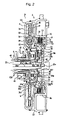
- FIG. 2 is a sectional view of a clutch assembly to which the present invention is applied, in which a one-way clutch is provided;
- FIG. 3 is a partial broken view representing the front of a damper device of the clutch assembly.
- FIG. 4 is a sectional view of a clutch assembly that has been partially modified.
- FIG. 1 shows a clutch assembly with no one-way clutch.
- FIG. 2 shows a clutch assembly with a one-way clutch.
- FIG. 4 shows a clutch assembly as a modified embodiment in which an input or a drive member and an output or a driven member of the damper device are reversed.
- the clutch assembly is connected to an internal combustion engine such as a gasoline engine to the right of the drawings, and connected to an automatic transmission, for example, a CVT, an automatic transmission with multiple speeds (6 forward speeds and 1 reverse speed) and the like to the left of the drawings.
- the clutch assembly has a clutch controller that engages the clutch 10 (described later) to transmit outputs of the engine to the automatic transmission such that the vehicle takes off.
- a clutch assembly 1 1 includes a housing 2 that forms an outer frame of the clutch assembly 1 1 .
- the housing 2 is formed by bonding a center piece 3 , a front cover 5 , a rear cover 6 and a rear hub 7 altogether by welding and the like.
- the center piece 3 and the front cover 5 are bonded at a welded point j 1 .
- the front cover 5 and the rear cover 6 are bonded at a welded point j 2 .
- the rear cover 6 and the rear hub 7 are bonded at a welded point j 3 .
- the front cover 5 constitutes a first housing member.
- the center piece 3 , the rear cover 6 and the rear hub 7 constitute a second housing member.
- the center piece 3 includes a protruding portion 3 a that fits with a crank shaft (not shown) or an engine output member of the engine, a hub 3 b , and a disc portion (front side surface) 3 c having a flat surface extending toward the outer radial direction.
- the front cover 5 includes a front side surface 5 a welded to an outer peripheral surface of the disc portion 3 c , an intermediate cylindrical portion 5 b that bends at substantially 90 degrees with respect to the front side surface 5 a and extends in an axial direction, a bent portion 5 c that bends at substantially 90 degrees with respect to the rear end portion of the cylindrical portion toward the outer radial direction, and an outer peripheral portion 5 d that extends in substantially an axial direction from an outer periphery of the bent portion 5 c .
- the rear cover 6 is welded to an end of the outer peripheral portion 5 d of the front cover 5 , and includes a rear side surface 6 a formed into an arm-like shape.
- the rear hub 7 includes a disc portion 7 a welded to an inner periphery of the rear surface 6 a , and a cylindrical portion 7 b that bends at 90 degrees with respect to the inner periphery of the disc portion 7 a , and extends in the axial direction.
- the intermediate cylindrical portion 5 b may be separated from the front cover such that they are joined by welding.
- a clutch 10 and a damper device 12 1 are housed in the housing 2 .
- the clutch 10 includes a wet-type multiple disc clutch in which a plurality of clutch plates (first friction members) 14 and clutch discs (second friction members) 13 are alternately disposed in the axial direction, and a hydraulic actuator 11 including a piston 20 (to be described later) and a cylinder for operating the clutch.
- a spline 15 is directly formed on the inner peripheral surface of the intermediate cylindrical portion 5 b of the front cover 5 . The spline 15 is brought into engagement with the clutch plates 14 as the outer friction plates so as to be fastened with a snap ring 14 a .
- a cylindrical clutch hub (clutch output member) 16 is disposed at an inner diameter side of the intermediate cylindrical portion 5 b .
- a spline 16 a formed on the outer peripheral surface of the clutch hub 16 is engaged with the clutch discs 13 as inner friction plates.
- the spline 15 is directly formed on the inner peripheral surface of the intermediate cylindrical portion 5 b so as to form a clutch drum directly on the front cover 5 .
- the clutch drum as being a separate element may be welded to the front cover 5 into one body.
- the center piece 3 has an annular groove 17 on an outer circumference of the disc portion 3 c located inside of the front cover 5 , and an annular groove 19 on an outer circumference of the hub portion 3 b .
- the piston 20 is oil tightly fit with the aforementioned annular grooves 17 , 19 via O-rings 21 , 22 , respectively.
- An oil chamber 23 that constitutes the hydraulic actuator 11 is defined by the piston 20 and the cylinder including the disc portion 3 c and the hub portion 3 b .
- the oil chamber 23 defined by the piston 20 and the housing 2 is disposed so as to be overlapped with the clutch plates 14 and the clutch discs 13 in the axial direction at the inner peripheries (inner radial side) thereof.
- the piston 20 has a collar 20 a that protrudes such that the inner periphery (inner radial side) thereof locates rearward in the axial direction (at the transmission side, inward of the housing).
- the O-ring 22 is slidably in contact with the inner peripheral surface of the collar 20 a .
- the piston 20 further has an outer periphery bent to protrude frontward in the axial direction (at the engine side, outward of the housing).
- the O-ring 21 is slidably in contact with the inner peripheral surface of the cylindrical portion 20 b .
- the oil chamber 23 may be defined by the piston 20 , the disc portion 3 c , the hub portion 3 b , and the intermediate cylindrical portion 5 c.
- the piston 20 extends to constitute a clutch operating portion.
- An end 20 c 1 of a projecting portion 20 c as the clutch operating portion is engaged with the spline 15 such that the piston is locked.
- the projecting portion 20 c has a protrusion 20 c 2 in the intermediate portion that abuts against the inner peripheral surface of the front surface 5 a of the front cover 5 .
- the position where the piston 20 makes a thrust is determined.
- the whole surface of the piston in the oil chamber 23 becomes an effective area to bear the pressure upon start of the oil pressure supply from the position where the piston is retracted. This makes it possible to start operation of the piston quickly.
- the projecting portion 20 c has a hole 20 d for discharging oil, and a concave groove 20 e.
- a retainer plate 25 is fastened to the hub portion 3 b of the center piece 3 with a snap ring.
- a return spring 26 is set under pressure between the retainer plate 25 and the back surface of the piston 20 .
- the center piece 3 has a concave portion 3 d formed at the side of the hub portion 3 b such that an input shaft 28 of the automatic transmission is fit in the concave portion 3 d .
- the input shaft has an oil hole 28 a formed therethrough in the axial direction.
- the oil hole 28 a is opened at the end of the input shaft.
- An O-ring 27 as a sealing device is fit between the input shaft and the concave portion 3 d of the center piece 3 .
- the center piece 3 has an oil hole 29 a that pierces therethrough from the concave portion 3 d and an oil hole 29 b that is formed between the oil hole 29 a and a corner of the hub portion 3 b such that a hydraulic pressure from the oil hole 28 a formed in the input shaft 28 is introduced from the opening of the oil hole 28 a into the oil chamber 23 via the oil holes (oil passages) 29 a , 29 b .
- the opening of the oil hole 28 a of the input shaft is led to the oil hole 29 a formed in the center piece 3 , only one O-ring 27 between the input shaft 28 and the center piece 3 is required.
- the blocked portion of the center piece requires no sealing device, thus simplifying the structure of the oil passage.
- a boss 30 serving as an output side of the clutch assembly 1 1 (output member) is spline coupled with the input shaft 28 , and a damper device 12 1 is housed in a large-diameter storage portion A defined by the bent portion 5 c and the rear cover 6 at the outer radial side of the boss 30 .
- the clutch 10 including the hydraulic actuator 11 is stored in a small-diameter storage portion B at the inner radial side of the intermediate cylindrical portion 5 b of the front cover.
- the damper device 12 1 has a drive plate 31 , an intermediate plate 32 , two driven plates 33 , and two kinds of coil springs 34 , 35 located on different radial positions, respectively such that the drive plate and the intermediate plate are interposed between the driven plates.
- connection plate 36 has an annular disc-like shape and is integrally formed with the clutch hub 16 through welding on the outer surface near the center.
- the outer periphery of the connection plate 36 is axially bent into a collar, on which a comb-like notch 36 a is formed.
- the connection plate 36 is connected to the drive plate 31 by engaging the notch 36 a with the outer periphery 31 a having concave/convex surface of the drive plate 31 .
- the inner periphery of the connection plate 36 constitutes a cylindrical hub portion 36 b that is slidably supported on the outer periphery 30 a of the boss 30 .
- An extending portion 33 a of the driven plate 33 is held by a ring member (ring portion) 37 so as to be integrally fixed with a rivet 38 to the boss 30 .
- a collar (protruding) portion 30 b that protrudes toward outer radial direction is formed to the front of the outer periphery of the boss 30 .
- the axial orientation of the hub portion 36 b of the connection plate 36 is defined between the collar portion 30 b and the extending portion 33 a . That is, the connection plate 36 abuts on the outer periphery (support portion) 30 a of the boss 30 and is supported by the extending portion 33 a (restricting member) of the driven plate and the collar portion 30 b that restricts its axial movement.
- the ring member 37 fixed to the boss has a short collar portion 37 a on the outer periphery.
- the inner periphery of the intermediate plate 32 abuts on the collar portion so as to support the intermediate plate 32 and the drive plate 31 .
- the boss 30 has a protrusion 30 d that is formed on the side surface of the intermediate portion and protrudes rearward.
- a thrust bearing 39 is interposed between the protrusion 30 d and the rear side surface 7 a of the rear hub 7 .
- a thrust bearing 40 is interposed between the front side surface of the boss 30 and the rear side surface of the hub portion 3 b of the center piece 3 .
- Those thrust bearings 39 , 40 serve to restrict the axial movements of the boss 30 , the damper device 12 1 that is integrally formed thereto, and the connection plate 36 that is supported by the boss 30 that restricts its axial movement so as to be supported.
- a spline 30 e formed in the inner periphery of the boss 30 is engaged with the spline 28 b formed in the input shaft 28 . Therefore the boss 30 serving as the output member is connected to the input shaft 28 of the automatic transmission, having both sides directly supported by the housing 2 via the thrust bearings 39 , 40 , respectively.
- a sleeve shaft 41 having a predetermined gap a is supported by the input shaft 28 via a bush 42 .
- a tip end of the sleeve shaft 41 is oil tightly fit with a hub portion 30 f of the boss via an O-ring 43 .
- a cylindrical portion 7 b of the rear hub 7 is disposed at an outer radial side of the sleeve shaft 41 in the presence of a predetermined gap b.
- the cylindrical portion 7 b is rotatively supported on a transmission case 45 via a bush 46 .
- the portion defined by the transmission case 45 and the cylindrical portion 7 b is oil tightly sealed with an oil seal 47 .
- a portion of the sleeve shaft 41 in contact with the bush 42 has a plurality of concave grooves 49 extending in the axial direction.
- a first oil passage is formed between the sleeve shaft 41 and the input shaft 28 for communicating the oil passage within the transmission case and the housing of the clutch assembly, which is defined by the gap a, the concave grooves 49 , and the spline 30 e or 28 b having its tooth partially cut.
- a second oil passage is formed of the gap b between the sleeve shaft 41 and the cylindrical portion 7 b of the rear hub.
- the supplied lubricating oil lubricates the thrust bearings 39 , 40 , the clutch 10 , the damper device 12 1 and the like within the housing 2 , and then discharged.
- portions between the outer peripheral surface 30 a of the boss that functions as a surface to support the connection plate 36 and the inner peripheral surface 36 b of the hub, and the collar portion 37 a of the ring member that functions as the surface for supporting the intermediate plate 32 are sufficiently lubricated.
- FIG. 3 is a partial broken view representing the front of the damper device 12 1 ( 12 2 ).
- the drive plate 31 formed into a ring shape has a concave-convex portion 31 a formed on the outer periphery so as to be engaged with the connection plate 36 .
- the drive plate 31 has a protruding portion 31 b formed on the inner periphery, which extends toward the inner radial direction.
- the ring shaped portion of the drive plate 31 has a hole 31 c that stores a coil spring (second spring) 34 with small diameter to which a predetermined pressure is applied.
- the intermediate plate 32 has a protruding portion 32 a that extends toward the outer radial direction on its outer periphery.
- a first spring 35 formed of two coil springs are set under pressure between the protruding portions 31 b and 32 a .
- the driven plates 33 disposed on both sides of the drive plate 31 and the intermediate plate 32 and are connected and fixed to those plates 31 , 32 with a pin 52 have spring housings 33 c , 33 d that store the first spring 35 and the second spring 34 , respectively.
- a first spring housing 33 c has a length enough to store two adjacent first springs 35 .
- a second spring housing 33 d has a length enough to include a predetermined allowance with respect to the second spring 34 .
- the rotation of the drive plate 31 is transmitted to the protruding portion 32 a while applying the pressure force to the first spring 35 from the protruding portion 31 b .
- the rotation transmitted to the protruding portion 32 a of the intermediate plate 32 is further transmitted to the driven plate 33 via the spring housing 33 c while applying the pressure force to the adjacent first spring 35 .
- Those two first springs 35 as being serially arranged are operated via the intermediate plate 32 such that the rotation is transmitted to the driven plate 33 while absorbing the impact acting on the drive plate 31 over a long stroke (long travel).
- a predetermined relative rotation between the drive plate 31 and the driven plate 33 caused by the two first springs 35 as being serially arranged serves to absorb the allowance between one end of the spring housing 33 d and the second spring 34 . Then the rotation of the drive plate 31 is transmitted to the driven plate 33 while applying pressure to the second spring 34 at the end of the housing. In addition to absorption of the predetermined torque upon compression of the first spring 35 , the impact can be absorbed in the middle of the stroke with a greater resistance upon exertion of the compressive deforming force of the second spring 34 .
- Each of the damper device 12 1 , 12 2 has the intermediate plate 32 such that the first springs 35 act on the portions between the drive plate 31 and the intermediate plate 32 , and between the intermediate plate 32 and the driven plate 33 .
- the first and the second springs 35 , 34 make it possible to increase the damper stroke so as to absorb the impact to the drive plate 31 over a relatively longer stroke upon transmission of the rotation to the driven plate 33 .
- This makes it possible to absorb fluctuations in the torque owing to the engine operation or upon engagement of the clutch 10 .
- the stroke established by placing the first springs 35 to be on the inner radial side with respect to the second spring 34 may become longer than the stroke established by placing the first springs 35 on the outer radial side. This is because the resultant rotational angle becomes relatively greater when the spring is disposed on the inner radial side compared with the spring disposed on the outer radial side.
- the clutch assembly 1 1 will be described.
- the oil pressure within the oil chamber 23 is released, the piston 20 is in a return position where the protruding portion 20 c2 is brought into abutment on the front cover 5 by the return spring 26 , and the clutch 10 is disengaged.
- the housing 2 connected to the internal combustion engine, rotates along with the rotation of the engine.
- the clutch 10 is disconnected, the rotation of the engine is not transmitted to the clutch hub 16 .
- the input shaft 28 is, thus, in a stopped state.
- a predetermined low oil pressure may be applied to the oil chamber 23 in order to bring the clutch 10 into a slip state such that the creep torque is applied to the input shaft 28 .
- the valve (not shown) is operated so as to supply a predetermined oil pressure to the oil hole 28 a of the input shaft 28 .
- the oil pressure is then supplied to the oil chamber 23 through the oil holes 29 a , 29 b .
- the reaction force of the clutch caused by the oil pressure acting on the oil chamber 23 directly acts on the disc portion 3 c of the housing that forms the oil chamber, and the intermediate cylindrical portion 5 b as the force in the opposite direction via the back-up plate 14 b and the snap ring 14 a .
- the reaction force therefore, is absorbed within the housing 2 directly without acting on the members other than the clutch assembly.
- the rotation of the housing 2 is transmitted to the damper device 12 1 via the clutch hub 16 and the connection plate 36 .
- the two adjacent first springs 35 arranged in series on the inner radial side serve to absorb the impact caused by the engagement of the clutch 10 over a long stroke.
- the second spring 34 disposed on the outer radial side serves to absorb further impact.
- the rotation is then transmitted to the driven plate 33 , and further to the input shaft 28 from the boss 30 that is integrally combined with the driven plate 33 .
- the damper device 12 1 having a larger radial size is stored in the large-diameter storage space A of the housing 2 .
- the springs 34 , 35 of the damper device 12 1 are released from the compression deformation to the normal states such that the rotation is transmitted in a substantially uniform condition.
- the hub portion 36 b of the connection plate 36 is axially oriented so as to be supported on the outer periphery 30 a of the boss 30 .
- the outer periphery 30 a rotates relatively to the hub portion 36 b along with the relative rotations between the drive plate 31 and the driven plate 33 .
- the hub portion 36 b and the outer periphery 30 a substantially rotate in an integrated manner.
- connection plate 36 is supported on the outer periphery 30 a of the boss for most of the times.
- the connection plate 36 does rotate relative to the outer periphery 30 a at a time of the impact absorption performed by the damper device.
- the connection plate 36 can be supported with no problems.
- the intermediate plate 32 is supported on the ring member 37 integrated with the boss 30 .
- the stroke and the stroke time of the intermediate plate 32 is shorter than that of the drive plate 31 , that is, the connection plate 36 integrated therewith and the relative rotation is performed in a sufficiently lubricated condition, those plates 32 , 31 can be supported with no problems.
- a space C is defined by the cylindrical portion 5 b and the outer periphery 5 d of the front cover 5 in the housing 2 .
- the space C is blocked by welding a lid member 55 to the front cover 5 .
- a flexible plate is connected to a screw hole 55 a such that the lid member 55 is connected to the internal combustion engine.
- the space C may be held in a hollow state.
- a predetermined load may be filled in the space C in case of necessity so as to enhance the fly-wheeling effect of the housing 2 .
- a motor-generator may be mounted in the space C so as to be employed as the drive unit for a hybrid vehicle (including an idling stop control).
- a ring gear 56 employed for an engine start-up device is also provided as shown in the figure.
- a clutch assembly 1 2 including a one-way clutch according to another embodiment will be described referring to FIG. 2 .
- This embodiment is substantially the same as the embodiment as described above except that the one-way clutch is provided.
- the main elements are designated as the reference numerals that are the same as those of the embodiment. The descriptions of those elements, thus, will be omitted.
- the rear portion of the boss 30 that supports the connection plate 36 is deeply cut, and the concave portion 30 g receives a one-way clutch 60 .
- An inner peripheral surface of an inner peripheral hub portion 30 f is engaged with the input shaft 28 with splines 30 e , 28 b .
- the one-way clutch 60 includes an outer race 61 , a sprag 62 , an inner race 63 , and left and right side plates 65 , and is positioned such that the outer race 61 is fit within the concave portion 30 g of the boss 30 .
- the rear portion of the outer race 61 that is, a ring extending portion (ring portion) 61 a extending toward the outer radial direction is fixed to the boss 30 together with the extending portion 33 a of the driven plate by the rivet 38 .
- the outer periphery of the ring extending portion 61 a has a collar shape, which abuts on the intermediate plate 32 so as to be supported.
- the inner race 63 has a sleeve 63 a with the inner circumference axially extending.
- the inner peripheral surface of the sleeve 63 a is fit with the sleeve shaft 41 and engaged with splines 63 b , 41 b .
- the boss 30 has a collar (protrusion) 30 a on a tip end of the outer peripheral surface (supporting portion) 30 a .
- the hub 36 b of the connection plate 36 is slidably supported on the outer peripheral surface, and is sandwitched between the collar portion 30 a and the extending portion 33 a of the driven plate so as to be supported and restricted with respect to its axial movement.
- the sleeve shaft 41 has a hole 41 c through which the input shaft 28 is communicated with the gap a of the sleeve shaft 41 , and the sleeve shaft 41 and the gap c of the sleeve 63 a .
- the first oil passage is communicated with the front side surface of the one-way clutch 60 , and with the housing 2 via the spline 30 having a cut portion or the spline 28 b and the thrust bearing 40 .
- the resultant lubricating oil passage that includes the first and the second oil passages is communicated with the housing 2 of the clutch assembly 1 2 from the transmission case 45 .
- the sleeve shaft 41 connected to the inner race 63 of the one-way clutch 60 via the sleeve 63 a is connected to a predetermined element of the device for selecting the speed among the forward and reverse speeds in the continuously variable transmission.
- the one-way clutch 60 is structured to restrict the rotation opposite to the running direction in the forward or the reverse range selected by the vehicle operator. In the case where the D range as the forward range is selected, the one-way clutch 60 restricts the rotation in the reverse direction so as to prevent the vehicle that stops uphill from being moved backward. In the case where the reverse range is selected, the one-way clutch 60 restricts the forward direction so as to prevent the vehicle that stops downhill from being moved forward.
- the clutch assembly of the modified embodiment has the damper device that is substantially the same as that of the embodiment as shown in FIG. 1 .
- the connection of those members thus, is different from that of the aforementioned embodiment.
- the main portions are designated as the same reference numerals. The description of those portions, thus, will be omitted.
- the clutch hub 16 of the clutch 10 has a spline 16 a that brings the clutch discs 13 into engagement at the outer radial side.
- the spline 16 a further extends to form an integrated clutch hub member 16 b having a cylindrical hub 16 c formed on its end.
- An extending portion 33 a of the drive plate 33 is integrally fixed to the extending portion (input member) 16 b as the integrated member with the rivet 70 and the like.
- the boss 30 serving as the output member has a cylindrical support portion (outer peripheral surface) 30 a formed on a front end, and a connecting portion 30 f as an extended rear end toward an outer radial direction.
- the end of the connecting portion 30 f is bent in the axial direction to form an edge portion (protrusion) 30 g .
- a connection plate 73 is fixed to be integrated with the connecting portion 30 f with the rivet 72 .
- the connecting portion 30 f is engaged with a concave/convex portion 31 a of the driven plate 31 by a notch 73 a formed on the end of the connection plate 73 .
- a thrust washer (latch member) 76 is fastened to the end of the support portion 30 a of the boss 30 with the snap ring (lock member) 75 .
- the hub portion 16 c of the clutch hub integrated member 16 b integrally combined with the drive plate (drive member) 33 is slidably supported on the support portion (outer peripheral surface) 30 a of the boss 30 .
- One end of the hub portion 16 c abuts on the thrust washer 76 , and the other end abuts on the tip of the edge portion 30 g of the boss 30 . Accordingly, the integrated member 16 b is supported while being restricted with respect to the axial movement.
- the torque from the clutch hub 16 is transmitted to the drive plate 33 in the damper device 12 2 .
- the damper device 12 2 absorbs the impact caused by the engagement of the clutch 10 over a long stroke by means of two first springs 35 disposed in series on the inner radial side.
- the damper device 12 2 further absorbs the impact in the middle of the long stroke by means of the second spring 34 disposed on the outer radial side.
- the torque is, then, transmitted to the driven plate 31 , and further to the boss 30 via the connection plate 73 .
- the clutch 10 is engaged/disengaged for connecting engine outputs to the input shaft 28 of the automatic transmission so as to start the vehicle without using the torque converter (T/C).
- the resultant transmission efficiency can be improved by reducing slip between input and output members employed in the torque converter.
- the present clutch assembly has the oil chamber 23 formed by fitting the piston 20 of the clutch 10 oil tightly with the housing 2 . Therefore, no leakage of oil from the oil chamber 23 to the housing 2 occurs, improving controllability of the clutch 10 .
- the present clutch assembly has a simple structure that does not require the clutch case formed of the member other than the housing 2 , which is employed for the clutch or the hydraulic actuator, thus improving reliability of the assembly.
- the position of the damper spring may be freely determined in the radial direction (longitudinal direction of the drawings as shown in FIGS. 1 , 2 , and 4 , respectively) of the damper devices 12 1 , 12 2 . This makes it possible to increase the degree of freedom in designing the damper devices 12 1 and 12 2 .
- the oil chamber 23 defined by the piston 20 and the housing 2 is disposed to be overlapped with the clutch plates 14 and the clutch discs 13 at the inner circumference thereof in the axial direction.
- the clutch 10 and each of the damper devices 12 1 , 12 2 are aligned in the axial direction, the length of the housing 2 in the axial direction is increased. However, such increase in the length can be kept to the minimum value.
- the housing 2 includes a connecting portion formed of the lid member 55 connected to an engine crank shaft (not shown), a front cover (first housing member) 5 to which the connecting portion is fixed, and a second housing member formed of a center piece 3 connected to the front cover 5 , a rear cover 6 and a rear hub 7 .
- the clutch plates 14 are fit with the spline 15 of the front cover 5 , the engine output torque is not transmitted through the welded points (bonded points) j 1 , j 2 between the first housing member 5 and the second housing member 3 , 6 , 7 .
- the strength of the housing 2 formed of a plurality of members may be easily established.
- the piston 20 is oil tightly fit with the center piece 3 or the like that forms the second housing member such that the clutch plates 14 and the clutch discs 13 are pressed upon supply of the oil pressure to the oil chamber 23 defined by the piston 20 and the center piece 3 . That is, the portion at which the front cover 5 and the center piece 3 are bonded is not formed within the oil chamber 23 . Therefore, even if a relatively higher oil pressure acts on the oil chamber 23 , the leakage of the oil may be reliably prevented.
- Each of the damper devices 12 1 , 12 2 includes the drive plate 31 , the driven plate 33 , the first springs 35 that act between the drive plate 31 and the driven plate 33 , and the second spring 34 that acts between the drive plate 31 and the driven plate 33 with a predetermined allowance. Then the drive plate 31 is connected to the clutch hub 16 , and the driven plate 33 is connected to the boss 30 . This makes it possible to align the clutch 10 and the damper device 12 1 or 12 2 in the axial direction even if the first and the second springs 35 , 34 are disposed for providing the damper characteristics. Therefore, the increase in each size of the clutch assemblies 1 1 , 1 2 , 1 3 in the radial direction may be prevented.
- the clutch assembly according to the present invention is useful as being employed for various types of vehicles having an internal combustion engine and an automatic transmission. It is preferable to apply the present invention especially to the clutch assembly that is demanded to have a simple structure and a high reliability.
Landscapes
- Engineering & Computer Science (AREA)
- General Engineering & Computer Science (AREA)
- Mechanical Engineering (AREA)
- Physics & Mathematics (AREA)
- Acoustics & Sound (AREA)
- Aviation & Aerospace Engineering (AREA)
- Hydraulic Clutches, Magnetic Clutches, Fluid Clutches, And Fluid Joints (AREA)
- Mechanical Operated Clutches (AREA)
Applications Claiming Priority (5)
| Application Number | Priority Date | Filing Date | Title |
|---|---|---|---|
| JP2001-246276 | 2001-08-14 | ||
| JP2001246276 | 2001-08-14 | ||
| JP2001-246277 | 2001-08-14 | ||
| JP2001246277 | 2001-08-14 | ||
| PCT/JP2002/008248 WO2003016736A1 (en) | 2001-08-14 | 2002-08-13 | Start clutch device |
Publications (2)
| Publication Number | Publication Date |
|---|---|
| US20040050647A1 US20040050647A1 (en) | 2004-03-18 |
| US7017724B2 true US7017724B2 (en) | 2006-03-28 |
Family
ID=26620533
Family Applications (1)
| Application Number | Title | Priority Date | Filing Date |
|---|---|---|---|
| US10/450,569 Expired - Fee Related US7017724B2 (en) | 2001-08-14 | 2003-09-10 | Clutch assembly |
Country Status (6)
| Country | Link |
|---|---|
| US (1) | US7017724B2 (ja) |
| EP (1) | EP1418359B1 (ja) |
| JP (4) | JP4267445B2 (ja) |
| KR (1) | KR100881792B1 (ja) |
| CN (1) | CN1323246C (ja) |
| WO (1) | WO2003016736A1 (ja) |
Cited By (10)
| Publication number | Priority date | Publication date | Assignee | Title |
|---|---|---|---|---|
| US20080006502A1 (en) * | 2006-07-05 | 2008-01-10 | Zf Friedrichshafen Ag | Clutch arrangement for the drive train of a vehicle |
| US20080264750A1 (en) * | 2007-04-27 | 2008-10-30 | Nsk-Warner K.K. | Starting clutch appartus |
| US20090145712A1 (en) * | 2007-12-10 | 2009-06-11 | Luk Lamellen Und Kupplungsbau Beteiligungs Kg | Power transmission mechanism |
| US20100133063A1 (en) * | 2007-08-02 | 2010-06-03 | Luk Lamellen Und Kupplungsbau Beteiligungs Kg | Device for damping vibrations, in particular a multi-step torsional vibration damper |
| US20110000756A1 (en) * | 2009-07-01 | 2011-01-06 | Gm Global Technology Operations, Inc. | Bi-directional impact absorption device for a clutch reaction plate |
| US20110114432A1 (en) * | 2009-11-17 | 2011-05-19 | Aisin Seiki Kabushiki Kaisha | Torque converter apparatus |
| US20120088589A1 (en) * | 2009-06-18 | 2012-04-12 | Roel Verhoog | Damper for coupling rotation of motor vehicle driving shafts |
| US20140027231A1 (en) * | 2011-03-31 | 2014-01-30 | Aisin Aw Co., Ltd. | Starting device |
| WO2014134250A1 (en) * | 2013-02-27 | 2014-09-04 | Schaeffler Technologies Gmbh & Co. Kg | A drive assembly for an automatic transmission including a clutch damper |
| US10132363B2 (en) * | 2012-02-02 | 2018-11-20 | Zf Friedrichshafen Ag | Clutch arrangement |
Families Citing this family (26)
| Publication number | Priority date | Publication date | Assignee | Title |
|---|---|---|---|---|
| DE10151654A1 (de) * | 2001-10-19 | 2003-04-30 | Zf Sachs Ag | Kupplungsanordnung |
| DE502004002172D1 (de) * | 2004-04-10 | 2007-01-11 | Borgwarner Inc | Kupplungseinrichtung, insbesondere Anfahrkupplungseinrichtung |
| DE102004030660A1 (de) * | 2004-06-24 | 2006-01-26 | Borgwarner Inc., Auburn Hills | Kupplung |
| KR100828689B1 (ko) | 2006-11-08 | 2008-05-09 | 현대자동차주식회사 | 차량용 자동 변속기 |
| JP2008309317A (ja) * | 2007-06-18 | 2008-12-25 | Aisin Aw Co Ltd | 発進装置 |
| DE102009004710B4 (de) * | 2008-01-31 | 2022-03-03 | Schaeffler Technologies AG & Co. KG | Kupplungsaggregat |
| JP5401821B2 (ja) | 2008-03-31 | 2014-01-29 | アイシン・エィ・ダブリュ株式会社 | 発進装置 |
| KR101405592B1 (ko) * | 2008-05-30 | 2014-06-10 | 현대자동차주식회사 | 하이브리드 차량의 발진 클러치 장치 |
| WO2010038670A1 (ja) | 2008-09-30 | 2010-04-08 | アイシン・エィ・ダブリュ 株式会社 | 自動変速機 |
| JP5195513B2 (ja) * | 2009-02-27 | 2013-05-08 | 日産自動車株式会社 | 車両のクラッチユニット |
| JP5388628B2 (ja) | 2009-03-02 | 2014-01-15 | 株式会社エクセディ | ダンパー機構 |
| JP5789944B2 (ja) * | 2010-09-24 | 2015-10-07 | アイシン精機株式会社 | トルク変動吸収装置 |
| MX350635B (es) * | 2011-09-23 | 2017-09-12 | Chrysler Group Llc | Aparato y método para embrague de transmisión automatizado llenado durante la operación intermitente del motor. |
| JP5667031B2 (ja) * | 2011-11-04 | 2015-02-12 | アイシン・エィ・ダブリュ株式会社 | 発進装置 |
| JP5589247B2 (ja) * | 2011-11-04 | 2014-09-17 | アイシン・エィ・ダブリュ株式会社 | 車両用駆動装置 |
| US8561499B1 (en) * | 2012-08-17 | 2013-10-22 | Chrysler Group Llc | Centrifugal pendulum absorber |
| KR101519269B1 (ko) | 2013-12-18 | 2015-05-11 | 현대자동차주식회사 | 발진 클러치장치 |
| JP6295690B2 (ja) * | 2014-02-04 | 2018-03-20 | スズキ株式会社 | バックトルクリミッターを有するクラッチ |
| JP6410509B2 (ja) * | 2014-08-04 | 2018-10-24 | 株式会社エフ・シー・シー | 鞍乗り型車両 |
| US20180208041A1 (en) * | 2015-09-18 | 2018-07-26 | Aisin Aw Co., Ltd. | Vehicle drive device |
| JP2018096454A (ja) * | 2016-12-13 | 2018-06-21 | 株式会社エクセディ | 振動低減装置 |
| JP7173701B2 (ja) * | 2019-02-14 | 2022-11-16 | トヨタ自動車株式会社 | 捩り振動低減装置 |
| US10808822B1 (en) * | 2019-05-10 | 2020-10-20 | Valeo Kapec Co., Ltd. | Hydrokinetic torque-coupling device having lock-up clutch with dual piston assembly and selectable one-way clutch |
| CN112283299B (zh) * | 2019-07-23 | 2024-09-27 | 舍弗勒技术股份两合公司 | 减振装置 |
| CN113565891B (zh) * | 2021-08-06 | 2024-09-17 | 星箭科技股份有限公司 | 一种自动离合器 |
| CN114183479B (zh) * | 2021-12-15 | 2025-04-01 | 华域动力总成部件系统(上海)有限公司 | 湿式离合减振装置 |
Citations (12)
| Publication number | Priority date | Publication date | Assignee | Title |
|---|---|---|---|---|
| JPS61189330A (ja) | 1985-02-13 | 1986-08-23 | Toyota Motor Corp | クラツチ装置 |
| JPH0516143A (ja) | 1991-07-10 | 1993-01-26 | Bridgestone Corp | タイヤ加硫機 |
| JPH08320030A (ja) | 1995-05-24 | 1996-12-03 | Aqueous Res:Kk | 発進装置 |
| JPH09177830A (ja) | 1995-12-14 | 1997-07-11 | Bayerische Motoren Werke Ag | 自動車用駆動装置 |
| JPH09184520A (ja) | 1995-12-28 | 1997-07-15 | Mitsubishi Motors Corp | 複板式クラッチ装置 |
| JP2000304065A (ja) | 1999-08-24 | 2000-10-31 | Nsk Warner Kk | 発進クラッチ |
| JP2001003955A (ja) | 1999-04-19 | 2001-01-09 | Nsk Warner Kk | 発進クラッチ |
| US6244401B1 (en) * | 1998-05-06 | 2001-06-12 | Luk Getriebe-Systeme Gmbh | Force transmitting apparatus |
| US6332521B1 (en) * | 1999-03-10 | 2001-12-25 | Nsk-Warner K.K. | Starting clutch |
| US6397996B1 (en) * | 1999-03-23 | 2002-06-04 | Nsk-Warner K.K. | Starting clutch |
| US6446779B1 (en) * | 1999-10-07 | 2002-09-10 | Nsk-Warner K.K. | Damper assembly |
| US6648117B2 (en) * | 2000-09-22 | 2003-11-18 | Nsk-Warner K.K. | Starting clutch and method for controlling same |
Family Cites Families (17)
| Publication number | Priority date | Publication date | Assignee | Title |
|---|---|---|---|---|
| JPS57179628A (en) * | 1981-04-28 | 1982-11-05 | Ishikawajima Harima Heavy Ind Co Ltd | Torsional vibration measuring apparatus for rotating shaft |
| US4509627A (en) | 1982-08-03 | 1985-04-09 | Aisin Warner Kabushiki Kaisha | Hydraulic centrifugal clutch |
| US4924978A (en) * | 1987-04-13 | 1990-05-15 | Kabushiki Kaisha Daiken Seisakusho | Lock-up device for torque converter |
| JPH01156324A (ja) * | 1987-12-14 | 1989-06-19 | Nippon Oil & Fats Co Ltd | ポリメリックペルオキシエステル |
| JPH01122537U (ja) * | 1988-02-16 | 1989-08-21 | ||
| JPH01165333U (ja) * | 1988-05-10 | 1989-11-20 | ||
| JPH05164143A (ja) * | 1991-12-12 | 1993-06-29 | Hino Motors Ltd | 油圧クラッチ |
| JPH05332400A (ja) * | 1992-05-26 | 1993-12-14 | Aisin Seiki Co Ltd | 捩じり振動緩衝装置 |
| JPH07127657A (ja) * | 1993-11-01 | 1995-05-16 | Aqueous Res:Kk | 半自動変速機のクラッチ機構 |
| JP3423410B2 (ja) * | 1994-05-16 | 2003-07-07 | アイシン・エィ・ダブリュ株式会社 | 自動変速機の変速制御装置 |
| JP3186550B2 (ja) * | 1995-11-02 | 2001-07-11 | トヨタ自動車株式会社 | フライホイール付油圧クラッチ装置 |
| JPH09303421A (ja) * | 1996-03-12 | 1997-11-25 | Nsk Warner Kk | ダンパ一体型発進装置 |
| JP3854661B2 (ja) * | 1996-05-29 | 2006-12-06 | 株式会社エクセディ | ロックアップ装置付きトルクコンバータ |
| JP4049942B2 (ja) * | 1999-06-16 | 2008-02-20 | ヴァレオユニシアトランスミッション株式会社 | 捩り振動減衰装置 |
| JP2001050314A (ja) * | 1999-07-21 | 2001-02-23 | Luk Lamellen & Kupplungsbau Gmbh | クラッチ |
| JP3625162B2 (ja) * | 1999-10-19 | 2005-03-02 | ジヤトコ株式会社 | 多板式ロックアップクラッチ付きトルクコンバータ |
| JP3682214B2 (ja) * | 2000-10-03 | 2005-08-10 | ヴァレオユニシアトランスミッション株式会社 | トルク伝達装置 |
-
2002
- 2002-08-13 EP EP02760620A patent/EP1418359B1/en not_active Expired - Lifetime
- 2002-08-13 JP JP2003521000A patent/JP4267445B2/ja not_active Expired - Fee Related
- 2002-08-13 CN CNB028031946A patent/CN1323246C/zh not_active Expired - Fee Related
- 2002-08-13 KR KR1020047000673A patent/KR100881792B1/ko not_active Expired - Fee Related
- 2002-08-13 WO PCT/JP2002/008248 patent/WO2003016736A1/ja not_active Ceased
-
2003
- 2003-09-10 US US10/450,569 patent/US7017724B2/en not_active Expired - Fee Related
-
2008
- 2008-08-18 JP JP2008210199A patent/JP2009002520A/ja active Pending
- 2008-08-18 JP JP2008210201A patent/JP2009008268A/ja not_active Withdrawn
- 2008-08-18 JP JP2008210200A patent/JP4837000B2/ja not_active Expired - Fee Related
Patent Citations (12)
| Publication number | Priority date | Publication date | Assignee | Title |
|---|---|---|---|---|
| JPS61189330A (ja) | 1985-02-13 | 1986-08-23 | Toyota Motor Corp | クラツチ装置 |
| JPH0516143A (ja) | 1991-07-10 | 1993-01-26 | Bridgestone Corp | タイヤ加硫機 |
| JPH08320030A (ja) | 1995-05-24 | 1996-12-03 | Aqueous Res:Kk | 発進装置 |
| JPH09177830A (ja) | 1995-12-14 | 1997-07-11 | Bayerische Motoren Werke Ag | 自動車用駆動装置 |
| JPH09184520A (ja) | 1995-12-28 | 1997-07-15 | Mitsubishi Motors Corp | 複板式クラッチ装置 |
| US6244401B1 (en) * | 1998-05-06 | 2001-06-12 | Luk Getriebe-Systeme Gmbh | Force transmitting apparatus |
| US6332521B1 (en) * | 1999-03-10 | 2001-12-25 | Nsk-Warner K.K. | Starting clutch |
| US6397996B1 (en) * | 1999-03-23 | 2002-06-04 | Nsk-Warner K.K. | Starting clutch |
| JP2001003955A (ja) | 1999-04-19 | 2001-01-09 | Nsk Warner Kk | 発進クラッチ |
| JP2000304065A (ja) | 1999-08-24 | 2000-10-31 | Nsk Warner Kk | 発進クラッチ |
| US6446779B1 (en) * | 1999-10-07 | 2002-09-10 | Nsk-Warner K.K. | Damper assembly |
| US6648117B2 (en) * | 2000-09-22 | 2003-11-18 | Nsk-Warner K.K. | Starting clutch and method for controlling same |
Non-Patent Citations (2)
| Title |
|---|
| Microfilm of the specification and drawings annexed to the request of Japanese Utility Model Application No. 18946/1988 (Laid-open No. 122537/1989) (Daikin Manufacturing Co., Ltd.), Aug. 21, 1989, Full text; Fig. 1. |
| Microfilm of the specification and drawings annexed to the request of Japanese Utility Model Application No. 61461/1988 (Laid-open No. 165333/1989) (Toyota Motor Corp.), Nov. 22, 1989, Full text; Fig. 3. |
Cited By (15)
| Publication number | Priority date | Publication date | Assignee | Title |
|---|---|---|---|---|
| US20080006502A1 (en) * | 2006-07-05 | 2008-01-10 | Zf Friedrichshafen Ag | Clutch arrangement for the drive train of a vehicle |
| US20080264750A1 (en) * | 2007-04-27 | 2008-10-30 | Nsk-Warner K.K. | Starting clutch appartus |
| US20100133063A1 (en) * | 2007-08-02 | 2010-06-03 | Luk Lamellen Und Kupplungsbau Beteiligungs Kg | Device for damping vibrations, in particular a multi-step torsional vibration damper |
| US20090145712A1 (en) * | 2007-12-10 | 2009-06-11 | Luk Lamellen Und Kupplungsbau Beteiligungs Kg | Power transmission mechanism |
| US8272985B2 (en) * | 2007-12-10 | 2012-09-25 | Schaeffler Technologies AG & Co. KG | Power transmission mechanism |
| US20120088589A1 (en) * | 2009-06-18 | 2012-04-12 | Roel Verhoog | Damper for coupling rotation of motor vehicle driving shafts |
| US8602901B2 (en) * | 2009-06-18 | 2013-12-10 | Valeo Embrayages | Damper for coupling rotation of motor vehicle driving shafts |
| US20110000756A1 (en) * | 2009-07-01 | 2011-01-06 | Gm Global Technology Operations, Inc. | Bi-directional impact absorption device for a clutch reaction plate |
| US8336689B2 (en) | 2009-07-01 | 2012-12-25 | GM Global Technology Operations LLC | Bi-directional impact absorption device for a clutch reaction plate |
| US20110114432A1 (en) * | 2009-11-17 | 2011-05-19 | Aisin Seiki Kabushiki Kaisha | Torque converter apparatus |
| US8695772B2 (en) * | 2009-11-17 | 2014-04-15 | Aisin Seiki Kabushiki Kaisha | Torque converter apparatus |
| US20140027231A1 (en) * | 2011-03-31 | 2014-01-30 | Aisin Aw Co., Ltd. | Starting device |
| US9027724B2 (en) * | 2011-03-31 | 2015-05-12 | Aisin Aw Co., Ltd. | Starting device |
| US10132363B2 (en) * | 2012-02-02 | 2018-11-20 | Zf Friedrichshafen Ag | Clutch arrangement |
| WO2014134250A1 (en) * | 2013-02-27 | 2014-09-04 | Schaeffler Technologies Gmbh & Co. Kg | A drive assembly for an automatic transmission including a clutch damper |
Also Published As
| Publication number | Publication date |
|---|---|
| JP4837000B2 (ja) | 2011-12-14 |
| EP1418359A4 (en) | 2006-07-05 |
| KR100881792B1 (ko) | 2009-02-03 |
| US20040050647A1 (en) | 2004-03-18 |
| EP1418359B1 (en) | 2011-12-14 |
| JP2009008267A (ja) | 2009-01-15 |
| EP1418359A1 (en) | 2004-05-12 |
| JP4267445B2 (ja) | 2009-05-27 |
| WO2003016736A1 (en) | 2003-02-27 |
| CN1323246C (zh) | 2007-06-27 |
| CN1476518A (zh) | 2004-02-18 |
| JP2009002520A (ja) | 2009-01-08 |
| KR20040020969A (ko) | 2004-03-09 |
| JPWO2003016736A1 (ja) | 2004-12-02 |
| JP2009008268A (ja) | 2009-01-15 |
Similar Documents
| Publication | Publication Date | Title |
|---|---|---|
| US7017724B2 (en) | Clutch assembly | |
| CN100472103C (zh) | 用于电动变速传动的扭矩减震器组件的液压回路 | |
| US8955658B2 (en) | Vehicle power transmission device | |
| JP4069777B2 (ja) | ハイブリッド車用駆動装置 | |
| US8974339B2 (en) | Vehicle power transmission device | |
| US8839922B2 (en) | Vehicle power transmission device | |
| US9097330B2 (en) | Vehicle power transmission device | |
| JP2010525267A (ja) | 原動機駆動車両用のトルク差または速度差応動クラッチ操作装置 | |
| JP3823650B2 (ja) | ハイブリッド車輌用駆動装置 | |
| US6878086B2 (en) | Automatic transmission | |
| US20080308378A1 (en) | Coupling device | |
| CN103119331A (zh) | 液力变矩器 | |
| JPS6053223B2 (ja) | 自動車用駆動装置 | |
| US20050137044A1 (en) | Multiple speed automatic transmission for motor vehicle | |
| JP4474357B2 (ja) | ツインクラッチ装置 | |
| JP3423410B2 (ja) | 自動変速機の変速制御装置 | |
| JP4599155B2 (ja) | 複式クラッチ装置 | |
| JP2022532175A (ja) | デュアルピストンアセンブリ及びセレクタブルワンウェイクラッチを有するロックアップクラッチを備えた流体力学的トルク結合装置 | |
| JP2001221255A (ja) | 4輪駆動車のトランスアクスル | |
| JP2824385B2 (ja) | 湿式クラッチ装置 | |
| JP2002070886A (ja) | カップリング及び発進クラッチ | |
| JP2025167209A (ja) | ハイブリッド車両の動力伝達装置 | |
| JP2023137521A (ja) | 動力伝達装置 | |
| JPH0226100B2 (ja) | ||
| JPS61189329A (ja) | クラツチ装置 |
Legal Events
| Date | Code | Title | Description |
|---|---|---|---|
| AS | Assignment |
Owner name: AISIN AW CO., LTD., JAPAN Free format text: ASSIGNMENT OF ASSIGNORS INTEREST;ASSIGNORS:HAYABUCHI, MASAHIRO;MAEDA, KOUJI;YAMASHITA, TOMOHIRO;AND OTHERS;REEL/FRAME:014645/0632;SIGNING DATES FROM 20030801 TO 20030827 Owner name: AISIN AW INDUSTRIES CO., LTD., JAPAN Free format text: ASSIGNMENT OF ASSIGNORS INTEREST;ASSIGNORS:HAYABUCHI, MASAHIRO;MAEDA, KOUJI;YAMASHITA, TOMOHIRO;AND OTHERS;REEL/FRAME:014645/0632;SIGNING DATES FROM 20030801 TO 20030827 |
|
| FPAY | Fee payment |
Year of fee payment: 4 |
|
| FPAY | Fee payment |
Year of fee payment: 8 |
|
| FEPP | Fee payment procedure |
Free format text: MAINTENANCE FEE REMINDER MAILED (ORIGINAL EVENT CODE: REM.) |
|
| LAPS | Lapse for failure to pay maintenance fees |
Free format text: PATENT EXPIRED FOR FAILURE TO PAY MAINTENANCE FEES (ORIGINAL EVENT CODE: EXP.) |
|
| STCH | Information on status: patent discontinuation |
Free format text: PATENT EXPIRED DUE TO NONPAYMENT OF MAINTENANCE FEES UNDER 37 CFR 1.362 |
|
| FP | Expired due to failure to pay maintenance fee |
Effective date: 20180328 |