US6825824B2 - Liquid crystal display and a driving method thereof - Google Patents
Liquid crystal display and a driving method thereof Download PDFInfo
- Publication number
- US6825824B2 US6825824B2 US09/773,603 US77360301A US6825824B2 US 6825824 B2 US6825824 B2 US 6825824B2 US 77360301 A US77360301 A US 77360301A US 6825824 B2 US6825824 B2 US 6825824B2
- Authority
- US
- United States
- Prior art keywords
- gray
- data
- signals
- lcd
- voltage
- Prior art date
- Legal status (The legal status is an assumption and is not a legal conclusion. Google has not performed a legal analysis and makes no representation as to the accuracy of the status listed.)
- Expired - Lifetime, expires
Links
Images




Classifications
-
- G—PHYSICS
- G09—EDUCATION; CRYPTOGRAPHY; DISPLAY; ADVERTISING; SEALS
- G09G—ARRANGEMENTS OR CIRCUITS FOR CONTROL OF INDICATING DEVICES USING STATIC MEANS TO PRESENT VARIABLE INFORMATION
- G09G3/00—Control arrangements or circuits, of interest only in connection with visual indicators other than cathode-ray tubes
- G09G3/20—Control arrangements or circuits, of interest only in connection with visual indicators other than cathode-ray tubes for presentation of an assembly of a number of characters, e.g. a page, by composing the assembly by combination of individual elements arranged in a matrix no fixed position being assigned to or needed to be assigned to the individual characters or partial characters
- G09G3/2007—Display of intermediate tones
- G09G3/2011—Display of intermediate tones by amplitude modulation
-
- G—PHYSICS
- G09—EDUCATION; CRYPTOGRAPHY; DISPLAY; ADVERTISING; SEALS
- G09G—ARRANGEMENTS OR CIRCUITS FOR CONTROL OF INDICATING DEVICES USING STATIC MEANS TO PRESENT VARIABLE INFORMATION
- G09G3/00—Control arrangements or circuits, of interest only in connection with visual indicators other than cathode-ray tubes
- G09G3/20—Control arrangements or circuits, of interest only in connection with visual indicators other than cathode-ray tubes for presentation of an assembly of a number of characters, e.g. a page, by composing the assembly by combination of individual elements arranged in a matrix no fixed position being assigned to or needed to be assigned to the individual characters or partial characters
- G09G3/34—Control arrangements or circuits, of interest only in connection with visual indicators other than cathode-ray tubes for presentation of an assembly of a number of characters, e.g. a page, by composing the assembly by combination of individual elements arranged in a matrix no fixed position being assigned to or needed to be assigned to the individual characters or partial characters by control of light from an independent source
- G09G3/36—Control arrangements or circuits, of interest only in connection with visual indicators other than cathode-ray tubes for presentation of an assembly of a number of characters, e.g. a page, by composing the assembly by combination of individual elements arranged in a matrix no fixed position being assigned to or needed to be assigned to the individual characters or partial characters by control of light from an independent source using liquid crystals
- G09G3/3611—Control of matrices with row and column drivers
- G09G3/3648—Control of matrices with row and column drivers using an active matrix
-
- G—PHYSICS
- G09—EDUCATION; CRYPTOGRAPHY; DISPLAY; ADVERTISING; SEALS
- G09G—ARRANGEMENTS OR CIRCUITS FOR CONTROL OF INDICATING DEVICES USING STATIC MEANS TO PRESENT VARIABLE INFORMATION
- G09G2320/00—Control of display operating conditions
- G09G2320/02—Improving the quality of display appearance
-
- G—PHYSICS
- G09—EDUCATION; CRYPTOGRAPHY; DISPLAY; ADVERTISING; SEALS
- G09G—ARRANGEMENTS OR CIRCUITS FOR CONTROL OF INDICATING DEVICES USING STATIC MEANS TO PRESENT VARIABLE INFORMATION
- G09G2320/00—Control of display operating conditions
- G09G2320/02—Improving the quality of display appearance
- G09G2320/0252—Improving the response speed
-
- G—PHYSICS
- G09—EDUCATION; CRYPTOGRAPHY; DISPLAY; ADVERTISING; SEALS
- G09G—ARRANGEMENTS OR CIRCUITS FOR CONTROL OF INDICATING DEVICES USING STATIC MEANS TO PRESENT VARIABLE INFORMATION
- G09G2340/00—Aspects of display data processing
- G09G2340/16—Determination of a pixel data signal depending on the signal applied in the previous frame
-
- G—PHYSICS
- G09—EDUCATION; CRYPTOGRAPHY; DISPLAY; ADVERTISING; SEALS
- G09G—ARRANGEMENTS OR CIRCUITS FOR CONTROL OF INDICATING DEVICES USING STATIC MEANS TO PRESENT VARIABLE INFORMATION
- G09G5/00—Control arrangements or circuits for visual indicators common to cathode-ray tube indicators and other visual indicators
- G09G5/36—Control arrangements or circuits for visual indicators common to cathode-ray tube indicators and other visual indicators characterised by the display of a graphic pattern, e.g. using an all-points-addressable [APA] memory
- G09G5/39—Control of the bit-mapped memory
Definitions
- the present invention relates to a Liquid Crystal Display (LCD) and a driving method thereof. More specifically, the present invention relates to an LCD and a driving method for providing compensated data voltage in order to improve a response time of the liquid crystal.
- LCD Liquid Crystal Display
- a liquid crystal layer having anisotropic permittivity is injected between two substrates of a panel, and the light transmittivity of the panel is controlled by applying and controlling the electric field. Desired images are obtained in such a manner.
- An LCD is one of the most commonly used portable flat panel display devices.
- the thin film transistor liquid crystal display (TFT-LCD) employing the TFT as a switching element is most widely used.
- TFT-LCDs As more TFT-LCDs have been used as display devices of computers and televisions, it becomes increasingly important to implement moving pictures on the TFT-LCD.
- conventional TFT-LCDs have a relatively slow response speed. So it is difficult to implement moving pictures on the conventional TFT-LCD.
- different type of TFT-LCD that uses the optically compensated band (OCB) mode or ferro-electric liquid crystal (FLC) has been developed.
- OCB optically compensated band
- FLC ferro-electric liquid crystal
- the structure of the conventional TFT-LCD panel must be modified to use the OCB mode or the FLC.
- an LCD comprises: a data gray signal modifier for receiving gray signals from a data gray signal source, and outputting modification gray signals by considering gray signals of present and previous frames; a data driver for changing the modification gray signals into corresponding data voltages and outputting image signals; a gate driver for sequentially supplying scanning signals; and an LCD panel comprising a plurality of gate lines for transmitting the scanning signals; a plurality of data lines, being insulated from the gate lines and crossing them, for transmitting the image signals; and a plurality of pixels, formed by an area surrounded by the gate lines and data lines and arranged as a matrix pattern, having switching elements connected to the gate lines and data lines.
- the data gray signal modifier comprises: a frame storage device for receiving the gray signals from the data gray signal source, storing the gray signals during a single frame, and outputting the same; a controller for controlling writing and reading the gray signals of the frame storage device; and a data gray signal converter for considering the gray signals of a present frame transmitted by the data gray signal source and the gray signals of a previous frame transmitted by the frame storage device, and outputting the modification gray signals.
- the LCD further comprises: a combiner for receiving the gray signals from the data gray signal source, combining the gray signals to be synchronized with the clock signal frequency with which the controller is synchronized, and outputting the combined gray signals to the frame storage device and the data gray signal converter; and a divider for dividing the gray signals output by the data gray signal converter so as to be synchronized with the frequency with which the gray signals transmitted by the data gray signal source are synchronized.
- an LCD driving method comprising a plurality of gate lines; a plurality of data lines being insulated from the gate lines and crossing them; and a plurality of pixels, formed by an area surrounded by the gate lines and data lines and arranged as a matrix pattern, having switching elements connected to the gate lines and data lines
- an LCD driving method comprises: (a) sequentially supplying scanning signals to the gate lines; (b) receiving image signals from an image signal source, and generating modification image signals by considering image signals of present and previous frames; and (c) supplying data voltages corresponding to the generated modification image signals to the data lines.
- FIG. 1 shows an equivalence circuit of an LCD pixel
- FIG. 2 shows data voltages and pixel voltages supplied by a prior driving method
- FIG. 3 shows a light transmission rate of the LCD according to a conventional driving method
- FIG. 4 shows a modeled relation between the voltage and permittivity of the LCD
- FIG. 5 shows a method for supplying the data voltage according to a first preferred embodiment of the present invention
- FIG. 6 shows a light transmission rate of the LCD when supplying the data voltage according to the first preferred embodiment of the present invention
- FIG. 7 shows a light transmission rate of the LCD when supplying the data voltage according to a second preferred embodiment of the present invention
- FIG. 8 shows an LCD according to the preferred embodiment of the present invention
- FIG. 9 shows a data gray signal modifier according to the preferred embodiment of the present invention.
- FIG. 10 shows a conversion table according to the first preferred embodiment of the present invention
- FIG. 11 shows a data gray signal modifier according to a second embodiment of the present invention.
- FIG. 12 conceptually shows an operation of the data gray signal modifier according to the first preferred embodiment of the present invention shown in FIG. 11;
- FIG. 13 conceptually shows an operation of the data gray signal modifier according to the second preferred embodiment of the present invention shown in FIG. 11;
- FIG. 14 shows a data gray signal modifier according to a third embodiment of the present invention.
- FIGS. 15 ( a ) to 15 ( c ) show a conversion process of the modified gray data computed according to the third preferred embodiment of the present invention.
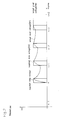
- FIG. 16 shows a waveform diagram for comparing the conventional voltage supply method with that according to the preferred embodiment of the present invention.
- the LCD comprises a plurality of gate lines which transmit scanning signals, a plurality of data lines which cross the gate lines and transmit image data, and a plurality of pixels which are formed by regions defined by the gate lines and data lines, and are interconnected through the gate lines, data lines, and switching elements.
- Each pixel of the LCD can be modeled as a capacitor having the liquid crystal as dielectric material, that is, a liquid crystal capacitor.
- FIG. 1 shows an equivalence circuit of the pixel of the LCD.
- the LCD pixel comprises a TFT 10 having a source electrode connected to a data line D m and a gate electrode connected to a gate line S n , a liquid crystal capacitor C 1 connected between a drain electrode of the TFT 10 and a common voltage V com , and a storage capacitor C st connected to the drain electrode of the TFT 10 .
- the data voltage V d supplied to the data line is supplied to each pixel electrode (not illustrated) via the TFT 10 .
- an electric field corresponding to a difference between the pixel voltage V p supplied to the pixel electrode and the common voltage V com is supplied to the liquid crystal (shown as the liquid crystal capacitor in FIG. 1) so that the light permeates the TFT with a transmission corresponding to a strength of the electric field.
- the pixel voltage V p is maintained during one frame period.
- the storage capacitor C st is used in an auxiliary manner so as to maintain the pixel voltage V p supplied to the pixel electrode.
- the liquid crystal capacitance C(0V) becomes ⁇ ⁇ A/d
- ⁇ ⁇ represents the permittivity when the liquid crystal molecules are arranged in parallel the LCD substrate, that is, when the liquid crystal molecules are arranged in the direction perpendicular to the direction of the light.
- A represents the area of the LCD substrate
- ‘d’ represents the distance between the substrates.
- the voltage for implementing a full black is set to be 5V
- the liquid crystal is arranged in the direction perpendicular to the substrate, and therefore, the liquid crystal capacitance C(5V) becomes ⁇ ⁇ A/d. Since g ⁇ ⁇ - ⁇ ⁇ >0 in the case of the liquid crystal used in the TN mode, the more the pixel voltage is supplied to the liquid crystal, the greater becomes the liquid crystal capacitance.
- the amount of charge necessary for making the n-th frame full black is C(5V) ⁇ 5V.
- the liquid crystal capacitance becomes C(0V) since the liquid crystal has not yet responded during the TFT's turn ON period.
- the n-th frame supplies 5V data voltage V d to the pixel
- the actual amount of the charge provided to the pixel becomes C(0V) ⁇ 5V
- C(0V) ⁇ C(5V) the pixel voltage below 5V (e.g., 3.5V) is actually supplied to the liquid crystal, and the full black is not implemented.
- the (n+1)th frame supplies 5V data voltage V d so as to implement the full black
- the amount of the charge actually provided to the liquid crystal becomes C(3.5V) ⁇ 5V.
- the voltage V p actually supplied to the liquid crystal ranges between 3.5V and 5V.
- the gray level of the present frame reaches the desired gray level after a few frames. It is because the gray level of the present frame is affected by the gray level of the previous frame.
- the permittivity of the pixel of the present frame reaches a desired value after a few frames since the permittivity of the pixel of the present frame is affected by that of the pixels of the previous frame.
- the n-th frame supplies 5V data voltage so as to implement the full black
- the amount of the charge corresponding to C(5V) ⁇ 5V is charged to the pixel since the liquid crystal capacitance is C(5V)
- the pixel voltage V p of the liquid crystal becomes 5V.
- the pixel voltage V p actually supplied to the liquid crystal is determined by the data voltage supplied to the present frame as well as the pixel voltage V p of the previous frame.
- FIG. 2 shows the data voltages and pixel voltages supplied by a conventional driving method.
- the data voltage V d corresponding to a target pixel voltage V w is conventionally supplied for each frame without regarding the pixel voltage V p of the previous frame.
- the actual pixel voltage V p supplied to the liquid crystal becomes lower or higher than the target pixel voltage by the liquid crystal capacitance corresponding to the pixel voltage of the previous frame, as described above.
- the pixel voltage V p reaches the target pixel voltage after a few frames.
- FIG. 3 shows a transmission rate of the LCD according to the conventional driving method.
- the transmission rate reaches the target transmission rate after a few frames even when the response time of the liquid crystal is within one frame.
- a picture signal S n of the present frame is compared with a picture signal S n ⁇ 1 of a previous frame so as to generate a modification signal S n ′ and the modified picture signal S n ′ is supplied to each pixel.
- the picture signal S n represents the data voltage in the case of analog driving methods.
- binary gray codes are used to control the data voltage in digital driving methods, the actual modification of the voltage supplied to the pixel is performed by the modification of the gray signal.
- the picture signal (the gray signal or data voltage) of the present frame is identical with the picture signal of the previous frame, the modification is not performed.
- the modification degree is proportional to the difference between the present gray signal (data voltage) and the gray signal (data voltage) of the previous frame.
- FIG. 4 shows a model exhibiting the relationship between the voltage and permittivity of the LCD.
- the horizontal axis represents the pixel voltage.
- the vertical axis represents a ratio between the permittivity ⁇ ( ⁇ ) at a certain level of pixel voltage v and the permittivity ⁇ ⁇ when the liquid crystal is arranged in parallel with the substrate; that is, when the liquid crystal lines perpendicular to the permeating direction of the light.
- V th to be 1V
- V max to be 4V.
- the V th and V max respectively represent the pixel voltages of the full white and full black (or vice versa).
- the storage capacitance C st When the capacitance of the storage capacitor (which will be referred to as the storage capacitance) is set to be identical to an average value ⁇ C l > of the liquid crystal capacitance, and the area of the LCD substrate and distance between the substrates are respectively set to be ‘A’ and ‘d’, the storage capacitance C st can be expressed as Equation 1.
- Equation 2 ⁇ ( ⁇ )/ ⁇ ⁇ can be expressed as Equation 2.
- Equation 3 Since total capacitance C(V) of the LCD is the sum of the liquid crystal and the storage capacitance, the capacitance C(V) can be expressed in Equation 3 from Equations 1 and 2.
- Equation 4 Since the charge Q supplied to the pixel is preserved, the following Equation 4 is established.
- V n represents the data voltage (or, an absolute value of the data voltage of an inverting driving method) to be supplied to the present frame
- C(V n ⁇ 1 ) represents the capacitance corresponding to the pixel voltage of the previous frame (that is, (n ⁇ 1)th frame)
- C(V f ) represents the capacitance corresponding to the actual voltage V f of the pixel of the present frame (that is, n-th frame).
- Equation 5 can be derived from Equations 3 and 4.
- V f ( ⁇ 3+ ⁇ square root over (9+4 V n ( V n ⁇ 1 +3))) ⁇ / 2 Equation 6
- the actual pixel voltage V f is determined by the data voltage V n supplied to the present frame and the pixel voltage V n ⁇ 1 supplied to the previous frame.
- the data voltage supplied in order for the pixel voltage to reach the target for voltage V n at the n-th frame is set to be V n ′
- the data voltage V n ′ can be expressed as Equation 7 from Equation 5.
- V n ⁇ 1 +3) ⁇ V n ′ ( V n +3) ⁇ V n Equation 7
- the pixel voltage can directly reach the target pixel voltage V n .
- Equation 8 is derived from FIG. 4 and a few assumptions, and the data voltage V n ′ applied to the general LCD can be expressed as Equation 9.
- the function f is determined by the characteristics of the LCD.
- the function f has the following characteristics.
- FIG. 5 shows the method for supplying the data voltage.
- the target voltage of the present frame is different from the pixel voltage of the previous frame
- the voltage higher (or lower) than the target voltage of the present frame is supplied as the modified data voltage so as to reach the target voltage level at the first frame, and after this, the target voltage is supplied as the data voltage at the following frames. This improves the response speed of the liquid crystal.
- the modified data voltage (charges) is determined by considering the liquid crystal capacitance determined by the pixel voltage of the previous frame. That is, the charge Q is supplied by considering the pixel voltage level of the previous frame so as to directly reach the target voltage level at the first frame.
- FIG. 6 shows a permittivity of the LCD in the case of supplying the data voltage according to the first preferred embodiment of the present invention. As shown, since the modified data voltage is supplied according to the first preferred embodiment, the permittivity directly reaches the target permittivity.
- a modified voltage V n ′ a little higher than the target voltage is supplied the pixel voltage.
- the permittivity becomes lower than the target permittivity before a half of the response time of the liquid crystal, but after this, the permittivity becomes overcompensated compared to the target value so that the average permittivity becomes equal to the target permittivity.
- FIG. 8 shows an LCD according to the preferred embodiment of the present invention.
- the LCD according to the preferred embodiment uses a digital driving method.
- the LCD comprises an LCD panel 100 , a gate driver 200 , a data driver 300 and a data gray signal modifier 400 .
- a plurality of gate lines S 1 , S 2 , . . . , Sn for transmitting gate ON signals, and a plurality of data lines D 1 , D 2 , . . . , Dn for transmitting the modified data voltages are formed on the LCD panel 100 .
- An area surrounded by the gate lines and data lines forms a pixel, and the pixel comprises TFTs 110 having a gate electrode connected to the gate line and having a source electrode connected to the data line, a pixel capacitor C 1 connected to a drain electrode of the TFT 110 , and a storage capacitor C st .
- the gate driver 200 sequentially supplies the gate ON voltage to the gate lines so as to turn on the TFT having a gate electrode connected to the gate line to which the gate ON voltage is supplied.
- the data gray signal modifier 400 receives n-bit data gray signals G n from a data gray signal source (e.g., a graphic signal controller), and outputs the m-bit modified data gray signals G n ′ after considering the m-bit data gray signals of the present and previous frames.
- a data gray signal source e.g., a graphic signal controller
- the data gray signal modifier 400 can be a stand-alone unit or can be integrated into a graphic card or an LCD module.
- the data driver 300 converts the modified gray signals G n ′ received from the data gray signal modifier 400 into corresponding gray voltages (data voltages) so as to supply the same to the data lines.
- FIG. 9 shows a detailed block diagram of the data gray signal modifier 400 of FIG. 8 .
- the data gray signal modifier 400 comprises a combiner 410 , a frame memory 420 , a controller 430 , a data gray signal converter 440 and a divider 450 .
- the combiner 410 receives gray signals from the data gray signal source, and converts the frequency of the data stream into a speed that can be processed by the data gray signal modifier 400 . For example, if 24-bit data synchronized with the 65 MHz frequency are transmitted from the data gray signal source and the processing speed of the components of the data gray signal modifier 400 is limited within 50 MHz, the combiner 410 combines the 24-bit gray signals into 48-bit gray signals G m two by two and then transmits the same to the frame memory 420 .
- the combined gray signals G m output the previous gray signals G m ⁇ 1 , stored in a predetermined address to the data gray signal converter 440 according to a control process by the controller 430 and concurrently stores the gray signals G m transmitted by the combiner 410 in the above-noted address.
- the data gray signal converter 440 receives the present frame gray signals G m output by the combiner and the previous frame gray signals G m ⁇ 1 output by the frame memory 420 , and generates modified gray signals G m ′ by processing the gray signals of the present and previous frames.
- the divider 450 divides 48-bit modified data gray signals G m ′ from the data gray signal converter 440 and outputs 24-bit modified gray signals G n ′.
- the combiner 410 and the divider 450 are needed, but in the case the clock frequency synchronized to the data gray signal is identical with that for accessing the frame memory 420 , the combiner 410 and the divider 450 are not needed.
- Any digital circuits that satisfy the above-defined equation 9 can be manufactured as the data gray signal converter 440 .
- the gray signals can be modified by accessing the lookup table.
- the lookup table makes the circuit simpler compared to the computation process.
- a truncation concept can be introduced. For example, it is assumed that the voltage from 0 to 8V is necessary when the liquid crystal is activated at voltage from 1 to 4V and a modification voltage is considered. At this time, when dividing the voltage having the range from 0 to 8V into 64 levels in order to perform a full modification, the number of the grays which can be actually represented becomes about 30 at most. Therefore, in the case the range of the voltage becomes 1 to 4V and the modified voltage V n ′ becomes greater than 4V, the number of the grays can be reduced if truncating all the modification voltages to 4V.
- FIG. 10 shows a configuration of the lookup table using the concept of the truncation according to the preferred embodiment of the present invention.
- the LCD driven by a digital method is described, and also the present invention can be applied to the LCD driven by an analog method.
- the pixel voltage reaches the target voltage level as the data voltage is modified and the modified data voltage is provided to the pixels. Therefore, the configuration of the TFT LCD panel does not have to be changed and the response time of the liquid crystal can be improved.
- FIG. 11 shows a detailed block diagram of the data gray signal modifier 400 according to a second preferred embodiment of the present invention.
- the data gray signal modifier 400 comprises a frame memory 460 , a controller 470 and a data gray signal converter 480 , and receives n-bit gray signals of the respective red (R), green (G) and blue (B) from the data gray signal source. Therefore, the total number of bits of the gray signals transmitted to the data gray signal converter 480 becomes (3 ⁇ n) bits.
- a skilled person can make either the (3 ⁇ n)-bit gray signals be concurrently supplied to the data gray signal modifier 480 from the data gray signal source, or make the respective n-bit R, G and B gray signals be sequentially supplied to the same.
- the frame memory 460 fixes the bit of the gray signal to be modified.
- the frame memory 460 receives m bits of the n-bit R, G and B gray signals from the data gray signal source, stores the same in predetermined addresses corresponding to the R, G and B, and outputs the same to the data gray signal converter 480 after a single frame delay. That is, the frame memory 460 receives the m-bit gray signals G, of the present frame and outputs m-bit gray signals G n ⁇ 1 of the previous frame.
- the data gray signal converter 480 receives (n-m) bits of the present frame G n which are passed through without modification, m bits of the present frame received for modification, and m bits of the previous frame G n ⁇ 1 delayed by the frame memory 460 , and then generates the modified gray signals G n ′ by considering the m bits of the present and previous frames.
- FIG. 12 conceptually shows an operation of the data gray signal modifier according to the first preferred embodiment of the present invention. It is assumed that the R, G and B gray signals transmitted to the data gray signal modifier 400 from the data gray signal source are respectively 8-bit signals.
- Two bits (bits of the present frame) starting from the LSB among 8-bit gray signals transmitted to the data gray signal modifier 400 are not modified, and they are input to the data gray signal converter 480 .
- the remaining 6 bits of the present frame are input to the data gray signal converter 480 for modification and concurrently stored in predetermined addresses of the frame memory 460 .
- the frame memory 460 stores the bit of the present frame during a single frame period and then outputs the same, 6-bit gray signals of the previous frame are output to the data gray signal converter 480 .
- the data gray signal converter 480 receives 6-bit R gray signals of the present frame and 6-bit R gray signals of the previous frame, generates modified gray signals considering the 6-bit R gray signals of the previous and present frames, adds the generated 6-bit gray signals and the 2-bit LSB gray signals of the present frame, and outputs finally modified 8-bit gray signals G n ′.
- the data gray signal converter 480 outputs modified 8-bit G and B gray signals considering the 6-bit gray signals of the present and previous frames.
- the 8-bit modified gray signals are converted into corresponding voltages by a data driver and supplied to the data lines.
- the 6-bit R, G and B gray signals are stored in the established addresses of the frame memory 460 .
- a skilled person can use a single frame memory 460 to assign the addresses for covering the R, G and B, or use three frame memories for the respective R, G and B to function as a single frame.
- the prior frame memory stores 8-bit R, G and B gray signals in the case of SXGA (1,280 ⁇ 1,024), and therefore at least 30 Mb memories are necessary, but the frame memory 460 according to the preferred embodiment of the present invention only stores 6-bit gray signals, thereby reducing memory capacity needed.
- FIG. 13 conceptually shows an operation of the data gray signal modifier according to the second preferred embodiment of the present invention.
- the data gray signal modifier is designed using one frame memory and one data gray signal converter.
- the number of the frame memories and the data gray signal converters can be changed according to grades of the LCD panels, the bit number of the gray signals, and designer's intention.
- three memories for configuring the frame memory and the data gray signal converter can be used to process R, G and B.
- a skilled person can configure the frame memory by using first and second memories for processing reading and writing processes corresponding to the respective R, G and B gray signals so as to enhance data processing speed.
- the gray signals are sequentially input to the frame memory, odd-numbered gray signals are stored in the first memory, and even-numbered gray signals are stored in the second memory, and when the odd-numbered gray signals are stored in the first memory, the second memory reads the first memory, and when the even-numbered gray signals are stored in the second memory, the first memory reads the second memory so that the data can be written/read to and from the frame memory within a shorter time.
- the configuration of the data gray signal modifier 400 is similar to that of the first preferred embodiment.
- the data gray signal modifier 400 of the second preferred embodiment is different from the first preferred embodiment because the data gray signal modifier 400 of the second preferred embodiment reduces the bit number of the output gray signals compared to the bit number of the input gray signals.
- the lower 3 bits of the 8-bit R gray signals are not modified and are passed though the dotted line in the figure, and the remaining 5 bits of the present frame are input to the data gray signal converter 480 and the frame memory 460 .
- the 5-bit R gray signals of the present frame input to the frame memory 460 are stored in predetermined addresses and then output at the next frame, and 5-bit R gray signals of the previous frame are output to the data gray signal converter 480 .
- the data gray signal converter 480 then receives the 5-bit R gray signals of the present and previous frames G n and G n ⁇ 1 generates the modified gray signals G n ′ proportional to the differences between the gray signals of the present and previous frames, and outputs the same.
- the modified R gray signals G n ′ are 8-bit signals obtained by an addition of the modified 5 bits and the unmodified 3 bits.
- Two bits of the 8-bit G gray signals are passed via the dotted line, and remaining 6-bit gray signals G n are input to the data gray signal converter 480 and the by frame memory 460 .
- the frame memory 460 stores the 6-bit G gray signals of the present frame in a predetermined address, and outputs the 6-bit G gray signals of the previous frame G n ⁇ 1 . Therefore, the data gray signal converter 480 outputs the modified gray signals G n ′ using the 6-bit G gray signals of the present and previous frames.
- the modified G gray signals G n ′ are obtained by an addition of the modified 6 bits and unmodified 2 bits.
- the frame memory 460 stores the 5-bit G gray signals of the present frame in a predetermined address and outputs the 5-bit G gray signals of the previous frame G n ⁇ 1 .
- the data gray signal converter 480 outputs modified gray signals G n ′ by using the 5-bit G gray signals of the present and previous frames.
- the modified G gray signals G n ′ are 8 bits obtained by an addition of the modified 5 bits and unmodified 3 bits.
- the passed bits among the 8-bit R, G and B gray signals start from the LSB, and a skilled person in the art can change the number of the passed bits.
- the skilled person in the art can change the capacity and number of the frame memories and modify the data gray signal converter.
- a digital circuit that satisfies Equation 9 can be manufactured as the data gray signal converter 480 according to the preferred embodiment, or a look-up table is made and then stored into a read only memory (ROM), and accessed to modify the gray signals. Since the modified data voltage V n ′ is not only proportional to the difference between the data voltage V n ⁇ 1 of the previous frame and the data voltage V n of the present frame, but is also dependent on absolute values of the data voltages, the lookup table makes the configuration of the circuit simpler than the computation.
- FIGS. 12 and 13 an example in which an LCD panel is the SXGA (1,280 ⁇ 1,024) type and 8-bit gray signals are supplied, will now be described.
- the frame memory requires at least 30 Mb.
- the data gray signal converter requires 512 Kb ⁇ 6 when processing two R, G and B pixels per one clock from the controller 470 . And it requires 512 Kb ⁇ 3 when processing one R, G and B pixel per one clock signal.
- the data gray signal modifier 400 receives 48-bit signals. Since the bus size of the memory is configured as ⁇ 4, ⁇ 8, ⁇ 16 and ⁇ 32, the 48-bit bus is configured using three 16-bit wide memories.
- the capacity of the frame memory and the data gray signal converter can be reduced.
- a number of modification bits are omitted when modifying the gray signals since human eyes are not as sensitive to moving pictures as to still pictures. Therefore, it is desirable to omit modification bits up to the number where the human eyes cannot discern the variation of the gray signals of the moving pictures.
- the data voltage is modified and the modified data voltage is supplied to the pixels so that the pixel voltage reaches the target voltage level.
- the response speed of the liquid crystal can be improved without changing the configuration of the TFT-LCD panel.
- FIGS. 9 and 11 an image signal modification circuit for improving the response speed of the liquid crystal is shown in FIGS. 9 and 11.
- the gray signals except a portion of the LSB are modified, and this algorithm is simple and easy to apply.
- DCC modification value 168 (10101000) gray level (G n ′) LO maximizes the response speed, when 208 (11010000) gray level (G n ⁇ 1 ) changes to 192 (11000000) gray level (G n ).
- a modification of the full 8 bits generates no problem.
- a modification of MSB 4 bits so as to reduce the cost cannot provide a room for the value 168 in the lookup table.
- the value of 176 (10110000) or 160 (10100000) is input to the lookup table. That is, modification errors are generated as much as the omitted LSB bits. This can generate a greater problem in the following interval.
- the second problem is as follows.
- a modification value be 176 gray level when the 208 gray level is switched to the 192 gray level. Then, 176 or 175 gray level must be provided to obtain a maximum liquid crystal response speed when the 207 gray level is switched to the 192 gray level.
- gray levels are distributed on a uniform screen of about 208 gray level.
- the difference of gray level 1 between the 208 and 207 gray levels may exaggerate the display defects, as the compensation difference widens.
- FIG. 14 shows a data gray signal modifier according to a third embodiment of the present invention.
- the same portions compared to FIG. 9 will be assigned with identical reference numerals and no further description will be provided.
- the data gray signal converter 460 of the data gray signal modifier comprises a lookup table 462 and a calculator 464 .
- the combiner 410 provides MSB 4-bit gray data G m [0:3] of the present frame and MSB 4-bit gray data G m ⁇ 1 [ 0 : 3 ] of the previous frame, the values f, a and b stored in the lookup table are extracted and provided to the calculator 464 .
- the calculator 464 receives the LSB 4-bit gray data G m [ 4 : 7 ] of the present frame from the combiner 410 , the LSB 4-bit gray data G m ⁇ 1 [ 4 : 7 ] of the previous frame from the frame memory 420 , the variables f, a and b to modify the moving pictures from the lookup table. Then it performs a predetermined computation and outputs first modified gray data G m ′[ 0 : 7 ] to the divider 450 .
- the first modified 36-bit gray data provided to the divider 450 are divided, and the modified 24-bit gray data G n ′ are output to the data driver 300 .
- the LCD driven by a digital method is described, and also the present invention can be is applied to the LCD driven by an analog method.
- the MSB y bits of the x bits are modified using the gray lookup table and the remaining z bits, that is (x-y) bits are modified by computation.
- [A]n is a multiple of the maximum 2 n not greater than A.
- [A] n is a value representing that n of the LSBs in A are all zeros.
- m [A] is a value representing that m of the MSBs in A are all zeros.
- m [A] n is a value representing that n of the LSBs and m of the MSBs in A are all zeros.
- G n ′ f ⁇ ( [ G n ] 4 , [ G n - 1 ] 4 ) + a ⁇ ( [ G n ] 4 , [ G n - 1 ] 4 ) ⁇ 4 ⁇ [ G n ] 16 - b ⁇ ( [ G n ] 4 , [ G n - 1 ] 4 ) ⁇ 4 ⁇ [ G n ] 16 Equation 10
- the quantization errors can be reduced by using the gray lookup table.
- the f, a and b are given as follows.
- Equation 11 can be used.
- G n ′ f ′ + [ G n ] 4 + a ⁇ ( [ G n ] 4 , [ G n - 1 ] 4 ) ⁇ 4 ⁇ [ G n ] 16 - b ⁇ ( [ G n ] 4 , [ G n - 1 ] 4 ) ⁇ 4 ⁇ [ G n ] 16 Equation 11
- Equation 12 can also be used.
- G n ′ f ′ ⁇ ( [ G n ] 4 , [ G n - 1 ] z ) + G n + a ′ ⁇ ( [ G n ] 4 , [ G n - 1 ] 4 ) ⁇ 4 ⁇ [ G n ] 16 - b ⁇ ( [ G n ] 4 , [ G n - 1 ] 4 ) ⁇ 4 ⁇ [ G n ] 16 Equation 12
- the size of the lookup table for the modified gray data decreases in the order of equation 10, equation 11 and equation 12, but the logic complication increases on the contrary.
- all the 8-bit data may not be stored when the capacity of the frame memory or the number of input/output pins should be reduced.
- the dimension of ⁇ 32 should be used so as to store 24-bit color information of the respective R, G and B, but it costs a lot.
- a dimension of ⁇ 16 can be used, and 5-bit R, 6-bit G and 5-bit G can only be stored.
- the gray values can be modified as follows.
- the modification gray values are output as follows.
- G n ′ f ⁇ ( [ G n ] 4 , [ G n - 1 ] 4 ) + a ⁇ ( [ G n ] 4 , [ G n - 1 ] 4 ) ⁇ 4 ⁇ [ G n ] 16 - b ⁇ ( [ G n ] 4 , [ G n - 1 ] 4 ) ⁇ 4 ⁇ [ G n ] ⁇ ⁇ ⁇ 2 4 Equation 13
- [G n ] 4 represents that zeros are provided to all the LSB 4 bits of G n
- [G n ⁇ 1 ] 4 represents that zeros are provided to all the LSB 4 bits of G n ⁇ 1
- 4 [G n ] represents that zeros are provided to all the MSB 4 bits of G n
- the values of a and b are positive integers
- 4 [G n ]>>2 functions such that binary data of the computed 4 [G n ] are shifted in the right direction by 2 bits, and as a result, it functions as divided by 2 2 .
- G n ′ f ⁇ ( [ G n ] 4 , [ G n - 1 ] 4 ) + a ⁇ ( [ G n ] 4 , [ G n - 1 ] 4 ) ⁇ 4 ⁇ [ G n ] 16 - b ⁇ ( [ G n ] 4 , [ G n - 1 ] 4 ) ⁇ 4 ⁇ [ G n ] ⁇ ⁇ ⁇ 3 2 Equation 14
- [G n ] 4 represents that zeros are provided to all the LSB 4 bits of G n
- [G n ⁇ 1 ] 4 represents that zeros are provided to all the LSB 4 bits of G n ⁇ 1
- 4 [G n ] represents that zeros are provided to all the MSB 4 bits of G n
- the values of a and b are positive integers
- 4 [G n ]>>3 functions such that binary data of the computed 4 [G n ] are shifted in the right direction by 3 bits, and as a result, it functions as divided by 2 3 .
- the pixel frequency may increase, rendering the high speed computation difficult.
- the gray data G n of the present frame can be modified omitting some LSBs.
- G n ′ f ⁇ ( [ G n ] 4 , [ G n - 1 ] 4 ) + a ⁇ ( [ G n ] 4 , [ G n - 1 ] 4 ) ⁇ 4 ⁇ [ G n ] ⁇ ⁇ ⁇ 2 4 - b ⁇ ( [ G n ] 4 , [ G n - 1 ] 4 ) ⁇ 4 ⁇ [ G n ] ⁇ ⁇ ⁇ 2 4 Equation 15
- G n ′ f ⁇ ( [ G n ] 8 - p , [ G n - 1 ] 8 - p ) + a ⁇ ( [ G n ] 8 - p , [ G n - 1 ] 8 - p ) ⁇ p ⁇ [ G n ] 8 - q ⁇ ⁇ ⁇ ( 8 - q ) 2 ( q - p ) - b ⁇ ( [ G n ] 8 - p , [ G n - 1 ] 8 - p ) ⁇ p ⁇ [ G n ] 8 - r ⁇ ⁇ ( 8 - r ) 2 ( r - p ) Equation 16
- image signals G n of a frame are modified compared to the image signals G n ⁇ 1 of a previous frame and using the equations 17 through 20.
- the response speed of the LCD panel becomes faster based on the following reasons.
- desired voltage is supplied. If 5V is supplied to liquid crystal cells, the actual 5V is supplied to the cells. When the liquid crystal reacts to the electric field and is the direction of the director of the liquid crystal is changed, the capacitance also changes. Accordingly, the voltage different from the previous one is supplied to the liquid crystal.
- the conventional AMLCD driving method does not provide accurate voltages because of the above-noted mechanism, but the voltage between the previous and present voltages. Accordingly, the actual response speed of the LCD panel is delayed more than one frame.
- the response time of the liquid crystal material generally becomes faster as the voltage varies a lot. For example, when rising, the response speed is faster when the voltage switches from 1V to 3V than when switching from 1V to 2V. When falling, the response speed is faster when the voltage switches from 3V to 1V than when switching from 3V to 2V.
- the response time of the liquid crystal exceeds the period of one frame (16.7 ms)
- the response time can be shortened within one frame period by a forced traction method.
- a response time of a liquid crystal is 30 ms when the voltage changes from 1V to 2V. In other words, in order to obtain the transmission corresponding to 2V, it takes 30 ms when 2V voltage is supplied.
- the liquid crystal reaches its target transmission corresponding to 2V before 30 ms. That is, when supplying 3V in order to obtain desired transmission corresponding to 2V, the liquid crystal reaches its target transmission corresponding to 2V in a time period shorter than 30 ms.
- the liquid crystal When continuously supplying 3V, the liquid crystal reaches 3V. Accordingly, the accessive voltage is cut off when the voltage reaches 2V, and then 2V is supplied. Then, the liquid crystal reaches 2V in a time period shorter than 30 ms. A time to cut off the voltage, that is, to switch the voltage is when the frame is switched. Therefore, if the voltage of the liquid crystal reaches 2V after a single frame (16.7 ms), 3V voltage is supplied for one frame and switched to 2V at a subsequent frame, effectively achieving the response time of 16.7 ms. In this case, the transmission errors during the response time (e.g., 16.7 ms) of the liquid crystal can be set off using the compensation method.
- the pixel voltage can reach the target voltage level by modifying the data voltage and supplying the modified data voltage to the pixels. Hence, the response speed of the liquid crystal can be improved without modifying the configuration of the TFT LCD panel.
- the size of the gray lookup table of the image signal modification circuit that enhances the response speed of the liquid crystal can be reduced and the quantization errors can be removed.
Landscapes
- Engineering & Computer Science (AREA)
- Physics & Mathematics (AREA)
- Computer Hardware Design (AREA)
- General Physics & Mathematics (AREA)
- Theoretical Computer Science (AREA)
- Chemical & Material Sciences (AREA)
- Crystallography & Structural Chemistry (AREA)
- Control Of Indicators Other Than Cathode Ray Tubes (AREA)
- Liquid Crystal Display Device Control (AREA)
- Liquid Crystal (AREA)
Priority Applications (4)
| Application Number | Priority Date | Filing Date | Title |
|---|---|---|---|
| US10/992,220 US7154459B2 (en) | 2000-02-03 | 2004-11-19 | Liquid crystal display and a driving method thereof |
| US11/504,194 US7365724B2 (en) | 2000-02-03 | 2006-08-15 | Liquid crystal display and driving method thereof |
| US12/107,332 US7667680B2 (en) | 2000-02-03 | 2008-04-22 | Liquid crystal display and driving method thereof |
| US12/651,736 US8035594B2 (en) | 2000-02-03 | 2010-01-04 | Liquid crystal display and driving method thereof |
Applications Claiming Priority (6)
| Application Number | Priority Date | Filing Date | Title |
|---|---|---|---|
| KR1020000005442A KR100670048B1 (ko) | 2000-02-03 | 2000-02-03 | 액정 표시 장치 및 그의 구동 방법 |
| KR2000-5442 | 2000-02-03 | ||
| KR2000-43509 | 2000-07-27 | ||
| KR1020000043509A KR20020010216A (ko) | 2000-07-27 | 2000-07-27 | 액정 표시 장치 및 그의 구동 방법 |
| KR2000-73672 | 2000-12-06 | ||
| KR1020000073672A KR100362475B1 (ko) | 2000-12-06 | 2000-12-06 | 액정 표시 장치와 이의 구동 장치 및 방법 |
Related Child Applications (1)
| Application Number | Title | Priority Date | Filing Date |
|---|---|---|---|
| US10/992,220 Division US7154459B2 (en) | 2000-02-03 | 2004-11-19 | Liquid crystal display and a driving method thereof |
Publications (2)
| Publication Number | Publication Date |
|---|---|
| US20010038372A1 US20010038372A1 (en) | 2001-11-08 |
| US6825824B2 true US6825824B2 (en) | 2004-11-30 |
Family
ID=27350162
Family Applications (5)
| Application Number | Title | Priority Date | Filing Date |
|---|---|---|---|
| US09/773,603 Expired - Lifetime US6825824B2 (en) | 2000-02-03 | 2001-02-02 | Liquid crystal display and a driving method thereof |
| US10/992,220 Expired - Lifetime US7154459B2 (en) | 2000-02-03 | 2004-11-19 | Liquid crystal display and a driving method thereof |
| US11/504,194 Expired - Lifetime US7365724B2 (en) | 2000-02-03 | 2006-08-15 | Liquid crystal display and driving method thereof |
| US12/107,332 Expired - Fee Related US7667680B2 (en) | 2000-02-03 | 2008-04-22 | Liquid crystal display and driving method thereof |
| US12/651,736 Expired - Fee Related US8035594B2 (en) | 2000-02-03 | 2010-01-04 | Liquid crystal display and driving method thereof |
Family Applications After (4)
| Application Number | Title | Priority Date | Filing Date |
|---|---|---|---|
| US10/992,220 Expired - Lifetime US7154459B2 (en) | 2000-02-03 | 2004-11-19 | Liquid crystal display and a driving method thereof |
| US11/504,194 Expired - Lifetime US7365724B2 (en) | 2000-02-03 | 2006-08-15 | Liquid crystal display and driving method thereof |
| US12/107,332 Expired - Fee Related US7667680B2 (en) | 2000-02-03 | 2008-04-22 | Liquid crystal display and driving method thereof |
| US12/651,736 Expired - Fee Related US8035594B2 (en) | 2000-02-03 | 2010-01-04 | Liquid crystal display and driving method thereof |
Country Status (5)
| Country | Link |
|---|---|
| US (5) | US6825824B2 (de) |
| EP (2) | EP1122711A3 (de) |
| JP (2) | JP5095889B2 (de) |
| CN (1) | CN1262867C (de) |
| TW (1) | TWI280547B (de) |
Cited By (26)
| Publication number | Priority date | Publication date | Assignee | Title |
|---|---|---|---|---|
| US20020024481A1 (en) * | 2000-07-06 | 2002-02-28 | Kazuyoshi Kawabe | Display device for displaying video data |
| US20030122854A1 (en) * | 2001-11-29 | 2003-07-03 | Yoshihisa Ooishi | Display controller and display device provided therewith |
| US20030151579A1 (en) * | 2002-02-08 | 2003-08-14 | Lee Baek-Woon | Liquid crystal display, driving method thereof and frame memory |
| US20030193460A1 (en) * | 2002-04-10 | 2003-10-16 | Samsung Electronics Co., Ltd. | Apparatus and method to improve a response speed of an LCD |
| US20030231158A1 (en) * | 2002-06-14 | 2003-12-18 | Jun Someya | Image data processing device used for improving response speed of liquid crystal display panel |
| US20040125064A1 (en) * | 2002-12-19 | 2004-07-01 | Takako Adachi | Liquid crystal display apparatus |
| US20050001802A1 (en) * | 2003-07-04 | 2005-01-06 | Seung-Woo Lee | Liquid crystal display apparatus and method for driving the same |
| US20050088398A1 (en) * | 2000-02-03 | 2005-04-28 | Lee Baek-Woon | Liquid crystal display and a driving method thereof |
| US20050253793A1 (en) * | 2004-05-11 | 2005-11-17 | Liang-Chen Chien | Driving method for a liquid crystal display |
| US20060092117A1 (en) * | 2004-10-29 | 2006-05-04 | Daisuke Kubota | Liquid crystal display device and method for driving the same |
| US20060109220A1 (en) * | 2001-09-04 | 2006-05-25 | Ham Yong S | Method and apparatus for driving liquid crystal display |
| US20060109276A1 (en) * | 2004-11-19 | 2006-05-25 | Nec Lcd Technologies, Ltd. | Data outputting method, data outputting device, liquid crystal panel driving device, and liquid crystal display device |
| US20060164370A1 (en) * | 2005-01-24 | 2006-07-27 | Chul-Woo Park | Liquid crystal display device |
| US20070091042A1 (en) * | 2005-10-25 | 2007-04-26 | Lg Philips Lcd Co., Ltd. | Flat display apparatus and picture quality controlling method thereof |
| US20070200811A1 (en) * | 2006-02-27 | 2007-08-30 | Lg.Philips Lcd Co., Ltd. | Apparatus and method for driving liquid crystal display device |
| US7289161B2 (en) * | 2003-01-24 | 2007-10-30 | Mitsubishi Denki Kabushiki Kaisha | Frame data compensation amount output device, frame data compensation device, frame data display device, and frame data compensation amount output method, frame data compensation method |
| US20070285377A1 (en) * | 2006-05-02 | 2007-12-13 | Epson Imaging Devices Corporation | Electro-optical device, circuit and method for driving the same, and electronic apparatus |
| US20080013126A1 (en) * | 2006-07-11 | 2008-01-17 | Hannstar Display Corporation | Liquid Crystal Display and Over Driving Method Thereof |
| US20080055220A1 (en) * | 2006-09-05 | 2008-03-06 | Yuri Azuma | Display control device, semiconductor integrated circuit device and mobile terminal device |
| US20080055219A1 (en) * | 2006-09-01 | 2008-03-06 | Lg.Philips Lcd Co., Ltd. | Display device and method of driving the same |
| US20080068390A1 (en) * | 2006-09-15 | 2008-03-20 | Tatsuya Ishii | Semiconductor integrated circuit device and mobile terminal device |
| US20080129672A1 (en) * | 2005-03-14 | 2008-06-05 | Tomoyuki Ishihara | Image Display Apparatus, Image Display Monitor and Television Receiver |
| US20080174576A1 (en) * | 2007-01-23 | 2008-07-24 | Lee Baek-Woon | Display device and driving method thereof |
| US20080180380A1 (en) * | 2007-01-29 | 2008-07-31 | Han-Yung Jung | Liquid crystal display device and method of driving the same |
| US20090040167A1 (en) * | 2007-08-06 | 2009-02-12 | Wein-Town Sun | Programmable nonvolatile memory embedded in a timing controller for storing lookup tables |
| TWI406243B (zh) * | 2008-12-19 | 2013-08-21 | Innolux Corp | 平面顯示裝置 |
Families Citing this family (82)
| Publication number | Priority date | Publication date | Assignee | Title |
|---|---|---|---|---|
| JP3470095B2 (ja) * | 2000-09-13 | 2003-11-25 | 株式会社アドバンスト・ディスプレイ | 液晶表示装置及びその駆動用回路装置 |
| JP2008242472A (ja) * | 2000-10-27 | 2008-10-09 | Mitsubishi Electric Corp | 液晶表示装置の駆動回路および駆動方法 |
| US6771242B2 (en) * | 2001-06-11 | 2004-08-03 | Lg. Philips Lcd Co., Ltd. | Method and apparatus for driving liquid crystal display |
| JP2003084736A (ja) * | 2001-06-25 | 2003-03-19 | Nec Corp | 液晶表示装置 |
| JP2003044017A (ja) * | 2001-08-03 | 2003-02-14 | Nec Corp | 画像表示装置 |
| KR100769166B1 (ko) * | 2001-09-04 | 2007-10-23 | 엘지.필립스 엘시디 주식회사 | 액정표시장치의 구동방법 및 장치 |
| KR100806903B1 (ko) * | 2001-09-27 | 2008-02-22 | 삼성전자주식회사 | 액정 표시 장치 및 이의 구동 방법 |
| JP3617498B2 (ja) * | 2001-10-31 | 2005-02-02 | 三菱電機株式会社 | 液晶駆動用画像処理回路、およびこれを用いた液晶ディスプレイ装置、ならびに画像処理方法 |
| TW575864B (en) * | 2001-11-09 | 2004-02-11 | Sharp Kk | Liquid crystal display device |
| KR100840316B1 (ko) * | 2001-11-26 | 2008-06-20 | 삼성전자주식회사 | 액정 표시 장치 및 그의 구동 방법 |
| KR100831228B1 (ko) * | 2002-01-30 | 2008-05-21 | 삼성전자주식회사 | 유기 전계발광 표시장치 및 그의 구동방법 |
| JP3924485B2 (ja) * | 2002-03-25 | 2007-06-06 | シャープ株式会社 | 液晶表示装置の駆動方法及びその液晶表示装置 |
| KR100864492B1 (ko) * | 2002-05-03 | 2008-10-20 | 삼성전자주식회사 | 액정 표시 장치 및 그 구동 방법 |
| KR100878267B1 (ko) * | 2002-05-08 | 2009-01-13 | 삼성전자주식회사 | 액정 표시 장치 |
| US7342564B2 (en) * | 2002-08-08 | 2008-03-11 | Lg. Philips Lcd Co., Ltd. | Method and apparatus for driving liquid crystal display |
| KR20040020317A (ko) * | 2002-08-30 | 2004-03-09 | 삼성전자주식회사 | 액정 표시 장치 및 그 구동 방법 |
| JP2004133159A (ja) * | 2002-10-10 | 2004-04-30 | Sanyo Electric Co Ltd | 液晶パネル駆動装置 |
| KR100890026B1 (ko) * | 2002-11-20 | 2009-03-25 | 삼성전자주식회사 | 액정 표시 장치의 구동 장치 및 그 방법 |
| KR100915234B1 (ko) * | 2002-12-17 | 2009-09-02 | 삼성전자주식회사 | 계조 전압의 선택 범위를 변경할 수 있는 액정 표시장치의 구동 장치 및 그 방법 |
| JP3703806B2 (ja) * | 2003-02-13 | 2005-10-05 | 三菱電機株式会社 | 画像処理装置、画像処理方法、および画像表示装置 |
| KR100697378B1 (ko) * | 2003-03-10 | 2007-03-20 | 비오이 하이디스 테크놀로지 주식회사 | 액정표시장치 및 그 구동방법 |
| KR100945577B1 (ko) * | 2003-03-11 | 2010-03-08 | 삼성전자주식회사 | 액정 표시 장치의 구동 장치 및 그 방법 |
| JP2004302160A (ja) * | 2003-03-31 | 2004-10-28 | Fujitsu Display Technologies Corp | 液晶表示装置 |
| CN100367767C (zh) * | 2003-04-02 | 2008-02-06 | 夏普株式会社 | 图像显示设备的驱动装置、图像显示设备以及电视接收器 |
| CN1323379C (zh) * | 2003-04-02 | 2007-06-27 | 友达光电股份有限公司 | 数据驱动电路及由其驱动数据的方法 |
| EP1467346B1 (de) * | 2003-04-07 | 2012-03-07 | Samsung Electronics Co., Ltd. | Flüssigkristallanzeige und Verfahren zu deren Ansteuerung |
| TWI259992B (en) | 2003-05-22 | 2006-08-11 | Au Optronics Corp | Liquid crystal display device driver and method thereof |
| KR100943278B1 (ko) * | 2003-06-09 | 2010-02-23 | 삼성전자주식회사 | 액정 표시 장치와 이의 구동 장치 및 방법 |
| CN100466056C (zh) * | 2003-06-11 | 2009-03-04 | 友达光电股份有限公司 | 液晶显示器的扫描方法 |
| JP4239892B2 (ja) * | 2003-07-14 | 2009-03-18 | セイコーエプソン株式会社 | 電気光学装置とその駆動方法ならびに投射型表示装置、電子機器 |
| KR100973813B1 (ko) | 2003-08-06 | 2010-08-03 | 삼성전자주식회사 | 액정 표시 장치 및 영상 신호 보정 방법 |
| TW200522721A (en) * | 2003-08-28 | 2005-07-01 | Samsung Electronics Co Ltd | Signal processing device and method, and display device including singal processing device |
| KR100968568B1 (ko) * | 2003-08-28 | 2010-07-08 | 삼성전자주식회사 | 신호 처리 장치 및 방법 |
| TWI230369B (en) * | 2003-10-01 | 2005-04-01 | Vastview Tech Inc | Driving circuit of a liquid crystal display and driving method thereof |
| TWI230291B (en) | 2003-11-17 | 2005-04-01 | Vastview Tech Inc | Driving circuit and driving method thereof for a liquid crystal display |
| KR100992133B1 (ko) * | 2003-11-26 | 2010-11-04 | 삼성전자주식회사 | 신호 처리 장치 및 방법 |
| CN100353409C (zh) * | 2003-12-02 | 2007-12-05 | 钰瀚科技股份有限公司 | 用来驱动一液晶显示面板的驱动电路 |
| JP2005172847A (ja) * | 2003-12-05 | 2005-06-30 | Sharp Corp | 液晶表示装置、並びに、それを用いた液晶テレビおよび液晶モニタ |
| EP1548698A1 (de) * | 2003-12-22 | 2005-06-29 | VastView Technology Inc. | Steuerschaltung einer Flüssigkristallanzeige und Steuerverfahren dafür |
| CN100367100C (zh) * | 2004-04-14 | 2008-02-06 | 财团法人工业技术研究院 | 使显示装置画面均匀化的方法和使画面均匀化的显示装置 |
| WO2005104079A1 (en) * | 2004-04-26 | 2005-11-03 | Koninklijke Philips Electronics N.V. | Enhanced overdrive for displays |
| JP2005316146A (ja) * | 2004-04-28 | 2005-11-10 | Fujitsu Display Technologies Corp | 液晶表示装置及びその処理方法 |
| KR100599770B1 (ko) * | 2004-05-25 | 2006-07-13 | 삼성에스디아이 주식회사 | 액정 표시 장치 및 이의 구동방법. |
| KR100637436B1 (ko) * | 2004-06-03 | 2006-10-20 | 삼성에스디아이 주식회사 | 액정 표시 장치 및 그 구동 방법 |
| EP1761912A1 (de) * | 2004-06-22 | 2007-03-14 | Koninklijke Philips Electronics N.V. | Ansteuerung einer flüssigkristallanzeige mit einem polaritätsumkehrungsmuster |
| KR101018754B1 (ko) * | 2004-10-04 | 2011-03-04 | 삼성전자주식회사 | 액정 표시 장치 및 영상 신호 보정 방법 |
| US8493299B2 (en) * | 2004-12-09 | 2013-07-23 | Sharp Kabushiki Kaisha | Image data processing device, liquid crystal display apparatus including same, display apparatus driving device, display apparatus driving method, program therefor, and storage medium |
| KR20060065956A (ko) * | 2004-12-11 | 2006-06-15 | 삼성전자주식회사 | 액정 표시 장치 및 표시 장치의 구동 장치 |
| KR101280310B1 (ko) | 2005-05-27 | 2013-07-01 | 티피오 디스플레이스 코포레이션 | 디스플레이 구동 방법 |
| CN100410982C (zh) * | 2005-06-30 | 2008-08-13 | 联咏科技股份有限公司 | 显示面板 |
| KR101160832B1 (ko) * | 2005-07-14 | 2012-06-28 | 삼성전자주식회사 | 표시 장치 및 영상 신호 보정 방법 |
| KR101152130B1 (ko) * | 2005-08-05 | 2012-06-15 | 삼성전자주식회사 | 박막 트랜지스터 표시판 및 그 제조 방법 |
| KR101240645B1 (ko) | 2005-08-29 | 2013-03-08 | 삼성디스플레이 주식회사 | 표시 장치 및 그 구동 방법 |
| KR20070035741A (ko) * | 2005-09-28 | 2007-04-02 | 삼성전자주식회사 | 액정 표시 장치 및 그 구동 방법 |
| JP4555207B2 (ja) | 2005-10-18 | 2010-09-29 | Necディスプレイソリューションズ株式会社 | 画質改善装置および画質改善方法 |
| KR101197222B1 (ko) * | 2005-10-19 | 2012-11-02 | 엘지디스플레이 주식회사 | 액정표시장치용 구동회로 및 그 구동방법 |
| US8384639B2 (en) * | 2006-02-07 | 2013-02-26 | Sharp Kabushiki Kaisha | Liquid crystal display device and method for emphasizing temporal signal change on a video signal based on at least a polarity for the video signal |
| KR101256011B1 (ko) * | 2006-04-17 | 2013-04-18 | 삼성디스플레이 주식회사 | 구동장치 및 이를 갖는 표시장치 |
| KR101254030B1 (ko) | 2006-06-27 | 2013-04-12 | 삼성디스플레이 주식회사 | 표시 장치와 이의 구동 장치 및 구동 방법 |
| CN101490737B (zh) * | 2006-09-12 | 2013-06-26 | 夏普株式会社 | 液晶驱动电路、驱动方法及液晶显示装置 |
| JP2008268384A (ja) * | 2007-04-17 | 2008-11-06 | Nec Lcd Technologies Ltd | 液晶表示装置 |
| JP5074820B2 (ja) | 2007-05-22 | 2012-11-14 | ルネサスエレクトロニクス株式会社 | 画像処理装置および画像処理方法 |
| JP5060864B2 (ja) * | 2007-08-06 | 2012-10-31 | ザインエレクトロニクス株式会社 | 画像信号処理装置 |
| JP5010391B2 (ja) * | 2007-08-17 | 2012-08-29 | ザインエレクトロニクス株式会社 | 画像信号処理装置 |
| CN101960510A (zh) * | 2008-03-11 | 2011-01-26 | 夏普株式会社 | 驱动电路、驱动方法、液晶显示面板、液晶组件、以及液晶显示装置 |
| KR101587913B1 (ko) * | 2008-06-02 | 2016-01-25 | 삼성디스플레이 주식회사 | 영상 신호 보정 장치 및 이를 포함한 액정 표시 장치 |
| CN101727848B (zh) * | 2008-10-10 | 2012-02-15 | 华映视讯(吴江)有限公司 | 液晶显示器的数据调整装置及其数据调整方法 |
| WO2010071635A1 (en) * | 2008-12-16 | 2010-06-24 | Hewlett-Packard Development Company, L.P. | Spatial light modulator |
| US8669973B2 (en) | 2009-05-29 | 2014-03-11 | Sharp Kabushiki Kaisha | Liquid crystal display element, liquid crystal display device, and method for displaying with liquid crystal display element |
| WO2011008724A2 (en) * | 2009-07-13 | 2011-01-20 | Dolby Laboratories Licensing Corporation | Systems and methods for controlling drive signals in spatial light modulator displays |
| US9007284B2 (en) | 2009-07-30 | 2015-04-14 | Sharp Kabushiki Kaisha | Liquid crystal display element, liquid crystal display device, and display method employed in liquid crystal display element |
| KR101600492B1 (ko) * | 2009-09-09 | 2016-03-22 | 삼성디스플레이 주식회사 | 표시장치 및 이의 구동방법 |
| US9214122B2 (en) | 2009-11-27 | 2015-12-15 | Sharp Kabushiki Kaisha | LCD device and television receiver |
| JP5403553B2 (ja) * | 2010-01-05 | 2014-01-29 | 株式会社ジャパンディスプレイ | 液晶表示装置及びその駆動方法 |
| US9335592B2 (en) | 2011-07-01 | 2016-05-10 | National University Corporation Tottori University | Liquid crystal display panel, liquid crystal display, and electronic unit |
| KR20130087927A (ko) * | 2012-01-30 | 2013-08-07 | 삼성디스플레이 주식회사 | 영상 신호 처리 장치 및 영상 신호 처리 방법 |
| CN104317085B (zh) * | 2014-11-13 | 2017-01-25 | 京东方科技集团股份有限公司 | 一种数据电压补偿方法、数据电压补偿装置和显示装置 |
| US10128571B2 (en) * | 2015-02-13 | 2018-11-13 | Kymeta Corporation | Counter electrode device, system and method for varying the permittivity of a liquid crystal device |
| CN104793423B (zh) * | 2015-05-11 | 2018-07-10 | 京东方科技集团股份有限公司 | 一种显示方法及装置 |
| JP2017044962A (ja) | 2015-08-28 | 2017-03-02 | 株式会社ジャパンディスプレイ | 液晶表示装置、液晶表示装置の駆動方法及び駆動処理装置 |
| KR101945225B1 (ko) * | 2018-06-08 | 2019-02-07 | (주)트라이시스 | 이미지 데이터 처리 방법 및 장치 |
| CN114530131A (zh) * | 2022-02-22 | 2022-05-24 | 北京京东方光电科技有限公司 | 调光面板的驱动方法、装置、电子设备及存储介质 |
Citations (3)
| Publication number | Priority date | Publication date | Assignee | Title |
|---|---|---|---|---|
| US5111195A (en) * | 1989-01-31 | 1992-05-05 | Sharp Kabushiki Kaisha | Driving circuit for a matrix type display device |
| US5465102A (en) * | 1991-04-17 | 1995-11-07 | Casio Computer Co., Ltd. | Image display apparatus |
| US5905484A (en) * | 1995-09-25 | 1999-05-18 | U.S. Philips Corporation | Liquid crystal display device with control circuit |
Family Cites Families (23)
| Publication number | Priority date | Publication date | Assignee | Title |
|---|---|---|---|---|
| JP2650479B2 (ja) * | 1989-09-05 | 1997-09-03 | 松下電器産業株式会社 | 液晶制御回路および液晶パネルの駆動方法 |
| JP3167351B2 (ja) * | 1990-09-03 | 2001-05-21 | 株式会社東芝 | 液晶表示装置 |
| NL9002516A (nl) * | 1990-11-19 | 1992-06-16 | Philips Nv | Weergeefinrichting en werkwijze ter vervaardiging daarvan. |
| WO1994001855A2 (en) * | 1992-06-30 | 1994-01-20 | Westinghouse Electric Corporation | Symmetric drive for an electroluminescent display panel |
| US5649083A (en) * | 1994-04-15 | 1997-07-15 | Hewlett-Packard Company | System and method for dithering and quantizing image data to optimize visual quality of a color recovered image |
| EP0741898B1 (de) * | 1994-11-24 | 2003-01-15 | Koninklijke Philips Electronics N.V. | Flüssigkristallanzeigegerät mit aktiver matrix und steurungsverfahren dafür zur kompensation von übersprechen |
| US5566064A (en) * | 1995-05-26 | 1996-10-15 | Apple Computer, Inc. | High efficiency supply for electroluminescent panels |
| JP3234131B2 (ja) * | 1995-06-23 | 2001-12-04 | 株式会社東芝 | 液晶表示装置 |
| JP3277121B2 (ja) | 1996-05-22 | 2002-04-22 | インターナショナル・ビジネス・マシーンズ・コーポレーション | 液晶デイスプレイの中間表示駆動方式 |
| JPH1039837A (ja) | 1996-07-22 | 1998-02-13 | Hitachi Ltd | 液晶表示装置 |
| JP3361705B2 (ja) | 1996-11-15 | 2003-01-07 | 株式会社日立製作所 | 液晶コントローラおよび液晶表示装置 |
| KR19980085824A (ko) | 1997-05-30 | 1998-12-05 | 문정환 | 반도체 소자의 배선 형성방법 |
| JP2001500994A (ja) * | 1997-07-22 | 2001-01-23 | コーニンクレッカ フィリップス エレクトロニクス エヌ ヴィ | 表示装置 |
| JPH1152906A (ja) | 1997-07-30 | 1999-02-26 | Fujitsu Ltd | 画像処理装置 |
| JP3305240B2 (ja) * | 1997-10-23 | 2002-07-22 | キヤノン株式会社 | 液晶表示パネル駆動装置と駆動方法 |
| JP3472473B2 (ja) | 1998-03-25 | 2003-12-02 | シャープ株式会社 | 液晶パネルの駆動方法および液晶表示装置 |
| JPH11326868A (ja) * | 1998-05-08 | 1999-11-26 | Seiko Epson Corp | 液晶表示装置 |
| US6278423B1 (en) * | 1998-11-24 | 2001-08-21 | Planar Systems, Inc | Active matrix electroluminescent grey scale display |
| JP2001201732A (ja) | 2000-01-21 | 2001-07-27 | Victor Co Of Japan Ltd | 液晶表示装置 |
| TWI280547B (en) * | 2000-02-03 | 2007-05-01 | Samsung Electronics Co Ltd | Liquid crystal display and driving method thereof |
| JP2002108294A (ja) * | 2000-09-28 | 2002-04-10 | Advanced Display Inc | 液晶表示装置 |
| JP3681121B2 (ja) * | 2001-06-15 | 2005-08-10 | キヤノン株式会社 | 駆動回路及び表示装置 |
| JP4288589B2 (ja) | 2003-11-14 | 2009-07-01 | 株式会社白寿生科学研究所 | スピーカ装置およびスピーカシステム |
-
2001
- 2001-01-30 TW TW090101788A patent/TWI280547B/zh not_active IP Right Cessation
- 2001-01-31 EP EP01102227A patent/EP1122711A3/de not_active Withdrawn
- 2001-01-31 EP EP08160307A patent/EP1995718A3/de not_active Withdrawn
- 2001-02-02 US US09/773,603 patent/US6825824B2/en not_active Expired - Lifetime
- 2001-02-03 CN CN01111679.XA patent/CN1262867C/zh not_active Expired - Fee Related
- 2001-02-05 JP JP2001028541A patent/JP5095889B2/ja not_active Expired - Fee Related
-
2004
- 2004-11-19 US US10/992,220 patent/US7154459B2/en not_active Expired - Lifetime
-
2006
- 2006-08-15 US US11/504,194 patent/US7365724B2/en not_active Expired - Lifetime
-
2008
- 2008-04-22 US US12/107,332 patent/US7667680B2/en not_active Expired - Fee Related
-
2010
- 2010-01-04 US US12/651,736 patent/US8035594B2/en not_active Expired - Fee Related
-
2012
- 2012-03-29 JP JP2012077273A patent/JP5781463B2/ja not_active Expired - Fee Related
Patent Citations (4)
| Publication number | Priority date | Publication date | Assignee | Title |
|---|---|---|---|---|
| US5111195A (en) * | 1989-01-31 | 1992-05-05 | Sharp Kabushiki Kaisha | Driving circuit for a matrix type display device |
| US5465102A (en) * | 1991-04-17 | 1995-11-07 | Casio Computer Co., Ltd. | Image display apparatus |
| US5844533A (en) * | 1991-04-17 | 1998-12-01 | Casio Computer Co., Ltd. | Gray scale liquid crystal display |
| US5905484A (en) * | 1995-09-25 | 1999-05-18 | U.S. Philips Corporation | Liquid crystal display device with control circuit |
Cited By (56)
| Publication number | Priority date | Publication date | Assignee | Title |
|---|---|---|---|---|
| US20060274007A1 (en) * | 2000-02-03 | 2006-12-07 | Lee Baek-Woon | Liquid crystal display and driving method thereof |
| US20100103158A1 (en) * | 2000-02-03 | 2010-04-29 | Samsung Electronics Co., Ltd | Liquid crystal display and driving method thereof |
| US8035594B2 (en) | 2000-02-03 | 2011-10-11 | Samsung Electronics Co., Ltd. | Liquid crystal display and driving method thereof |
| US7154459B2 (en) * | 2000-02-03 | 2006-12-26 | Samsung Electronics Co., Ltd. | Liquid crystal display and a driving method thereof |
| US7365724B2 (en) | 2000-02-03 | 2008-04-29 | Samsung Electronics Co., Ltd. | Liquid crystal display and driving method thereof |
| US20080191986A1 (en) * | 2000-02-03 | 2008-08-14 | Samsung Electronics Co., Ltd | Liquid crystal display and driving method thereof |
| US7667680B2 (en) | 2000-02-03 | 2010-02-23 | Samsung Electronics Co., Ltd. | Liquid crystal display and driving method thereof |
| US20050088398A1 (en) * | 2000-02-03 | 2005-04-28 | Lee Baek-Woon | Liquid crystal display and a driving method thereof |
| US20020024481A1 (en) * | 2000-07-06 | 2002-02-28 | Kazuyoshi Kawabe | Display device for displaying video data |
| US7158107B2 (en) | 2000-07-06 | 2007-01-02 | Hitachi, Ltd. | Display device for displaying video data |
| US20060109220A1 (en) * | 2001-09-04 | 2006-05-25 | Ham Yong S | Method and apparatus for driving liquid crystal display |
| US7528850B2 (en) * | 2001-09-04 | 2009-05-05 | Lg Display Co., Ltd. | Method and apparatus for driving liquid crystal display |
| US20030122854A1 (en) * | 2001-11-29 | 2003-07-03 | Yoshihisa Ooishi | Display controller and display device provided therewith |
| US7164415B2 (en) | 2001-11-29 | 2007-01-16 | Hitachi, Ltd. | Display controller and display device provided therewith |
| US7002538B2 (en) * | 2002-02-08 | 2006-02-21 | Samsung Electronics Co., Ltd. | Liquid crystal display, driving method thereof and frame memory |
| US20030151579A1 (en) * | 2002-02-08 | 2003-08-14 | Lee Baek-Woon | Liquid crystal display, driving method thereof and frame memory |
| US7221347B2 (en) | 2002-04-10 | 2007-05-22 | Samsung Electronics Co., Ltd. | Apparatus and method to improve a response speed of an LCD |
| US20030193460A1 (en) * | 2002-04-10 | 2003-10-16 | Samsung Electronics Co., Ltd. | Apparatus and method to improve a response speed of an LCD |
| US7034788B2 (en) * | 2002-06-14 | 2006-04-25 | Mitsubishi Denki Kabushiki Kaisha | Image data processing device used for improving response speed of liquid crystal display panel |
| US20030231158A1 (en) * | 2002-06-14 | 2003-12-18 | Jun Someya | Image data processing device used for improving response speed of liquid crystal display panel |
| US7239298B2 (en) * | 2002-12-19 | 2007-07-03 | Sharp Kabushiki Kaisha | Liquid crystal display apparatus |
| US7782288B2 (en) | 2002-12-19 | 2010-08-24 | Sharp Kabushiki Kaisha | Liquid crystal display apparatus |
| US20070222731A1 (en) * | 2002-12-19 | 2007-09-27 | Takako Adachi | Liquid crystal display apparatus |
| US20040125064A1 (en) * | 2002-12-19 | 2004-07-01 | Takako Adachi | Liquid crystal display apparatus |
| US7289161B2 (en) * | 2003-01-24 | 2007-10-30 | Mitsubishi Denki Kabushiki Kaisha | Frame data compensation amount output device, frame data compensation device, frame data display device, and frame data compensation amount output method, frame data compensation method |
| US7304624B2 (en) * | 2003-07-04 | 2007-12-04 | Samsung Electronics Co., Ltd. | Liquid crystal display apparatus and method for driving the same |
| US20050001802A1 (en) * | 2003-07-04 | 2005-01-06 | Seung-Woo Lee | Liquid crystal display apparatus and method for driving the same |
| US20050253793A1 (en) * | 2004-05-11 | 2005-11-17 | Liang-Chen Chien | Driving method for a liquid crystal display |
| US8164557B2 (en) | 2004-10-29 | 2012-04-24 | Semiconductor Energy Laboratory Co., Ltd. | Liquid crystal display device and method for driving the same |
| US20060092117A1 (en) * | 2004-10-29 | 2006-05-04 | Daisuke Kubota | Liquid crystal display device and method for driving the same |
| US20060109276A1 (en) * | 2004-11-19 | 2006-05-25 | Nec Lcd Technologies, Ltd. | Data outputting method, data outputting device, liquid crystal panel driving device, and liquid crystal display device |
| US7679619B2 (en) * | 2004-11-19 | 2010-03-16 | Nec Lcd Technologies, Ltd. | Data outputting method, data outputting device, liquid crystal panel driving device, and liquid crystal display device |
| US7522143B2 (en) * | 2005-01-24 | 2009-04-21 | Samsung Mobile Display Co., Ltd. | Liquid crystal display device |
| US20060164370A1 (en) * | 2005-01-24 | 2006-07-27 | Chul-Woo Park | Liquid crystal display device |
| US20080129672A1 (en) * | 2005-03-14 | 2008-06-05 | Tomoyuki Ishihara | Image Display Apparatus, Image Display Monitor and Television Receiver |
| US8130246B2 (en) * | 2005-03-14 | 2012-03-06 | Sharp Kabushiki Kaisha | Image display apparatus, image display monitor and television receiver |
| US7786971B2 (en) * | 2005-10-25 | 2010-08-31 | Lg. Display Co., Ltd. | Flat display apparatus capable of compensating a panel defect electrically and picture quality controlling method thereof |
| US20070091042A1 (en) * | 2005-10-25 | 2007-04-26 | Lg Philips Lcd Co., Ltd. | Flat display apparatus and picture quality controlling method thereof |
| US8059143B2 (en) | 2005-10-25 | 2011-11-15 | Lg Display Co., Ltd. | Flat display apparatus capable of compensating a panel defect electrically and picture quality controlling method thereof utilizing dithering |
| US20110007090A1 (en) * | 2005-10-25 | 2011-01-13 | Lg Display Co., Ltd. | Flat display apparatus capable of compensating a panel defect electrically and picture quality controlling method thereof |
| US20070200811A1 (en) * | 2006-02-27 | 2007-08-30 | Lg.Philips Lcd Co., Ltd. | Apparatus and method for driving liquid crystal display device |
| US7843412B2 (en) * | 2006-02-27 | 2010-11-30 | Lg Display Co., Ltd. | Apparatus and method for driving liquid crystal display device |
| US20070285377A1 (en) * | 2006-05-02 | 2007-12-13 | Epson Imaging Devices Corporation | Electro-optical device, circuit and method for driving the same, and electronic apparatus |
| US20080013126A1 (en) * | 2006-07-11 | 2008-01-17 | Hannstar Display Corporation | Liquid Crystal Display and Over Driving Method Thereof |
| US7884791B2 (en) | 2006-07-11 | 2011-02-08 | Hannstar Display Corporation | Liquid crystal display and over driving method thereof |
| US20080055219A1 (en) * | 2006-09-01 | 2008-03-06 | Lg.Philips Lcd Co., Ltd. | Display device and method of driving the same |
| US8035591B2 (en) * | 2006-09-01 | 2011-10-11 | Lg Display Co., Ltd. | Display device and method of driving the same |
| US20080055220A1 (en) * | 2006-09-05 | 2008-03-06 | Yuri Azuma | Display control device, semiconductor integrated circuit device and mobile terminal device |
| US20080068390A1 (en) * | 2006-09-15 | 2008-03-20 | Tatsuya Ishii | Semiconductor integrated circuit device and mobile terminal device |
| US7889164B2 (en) * | 2006-09-15 | 2011-02-15 | Renesas Electronics Corporation | Semiconductor integrated circuit device and mobile terminal device |
| US20080174576A1 (en) * | 2007-01-23 | 2008-07-24 | Lee Baek-Woon | Display device and driving method thereof |
| US8368623B2 (en) | 2007-01-23 | 2013-02-05 | Samsung Display Co., Ltd. | Display device and driving method thereof |
| US7911431B2 (en) * | 2007-01-29 | 2011-03-22 | Lg Display Co., Ltd. | Liquid crystal display device and method of driving the same |
| US20080180380A1 (en) * | 2007-01-29 | 2008-07-31 | Han-Yung Jung | Liquid crystal display device and method of driving the same |
| US20090040167A1 (en) * | 2007-08-06 | 2009-02-12 | Wein-Town Sun | Programmable nonvolatile memory embedded in a timing controller for storing lookup tables |
| TWI406243B (zh) * | 2008-12-19 | 2013-08-21 | Innolux Corp | 平面顯示裝置 |
Also Published As
| Publication number | Publication date |
|---|---|
| US20010038372A1 (en) | 2001-11-08 |
| US20050088398A1 (en) | 2005-04-28 |
| JP5095889B2 (ja) | 2012-12-12 |
| TWI280547B (en) | 2007-05-01 |
| CN1310434A (zh) | 2001-08-29 |
| US20080191986A1 (en) | 2008-08-14 |
| US7365724B2 (en) | 2008-04-29 |
| US8035594B2 (en) | 2011-10-11 |
| US20060274007A1 (en) | 2006-12-07 |
| EP1122711A3 (de) | 2001-09-12 |
| US7154459B2 (en) | 2006-12-26 |
| CN1262867C (zh) | 2006-07-05 |
| JP5781463B2 (ja) | 2015-09-24 |
| EP1122711A2 (de) | 2001-08-08 |
| EP1995718A2 (de) | 2008-11-26 |
| JP2001265298A (ja) | 2001-09-28 |
| US7667680B2 (en) | 2010-02-23 |
| US20100103158A1 (en) | 2010-04-29 |
| JP2012137782A (ja) | 2012-07-19 |
| EP1995718A3 (de) | 2011-03-23 |
Similar Documents
| Publication | Publication Date | Title |
|---|---|---|
| US6825824B2 (en) | Liquid crystal display and a driving method thereof | |
| US7095393B2 (en) | Liquid crystal display and a driving method thereof | |
| KR100593765B1 (ko) | 액정 표시 장치 및 그 구동 방법 | |
| JP5419860B2 (ja) | 駆動装置 | |
| JP2761128B2 (ja) | 液晶表示装置 | |
| US7298352B2 (en) | Apparatus and method for correcting gamma voltage and video data in liquid crystal display | |
| CN100461249C (zh) | 液晶显示器及其驱动设备 | |
| US20030132906A1 (en) | Gray scale display reference voltage generating circuit and liquid crystal display device using the same | |
| KR20020010216A (ko) | 액정 표시 장치 및 그의 구동 방법 | |
| KR100796748B1 (ko) | 액정 표시 장치와 이의 구동 장치 | |
| KR100514080B1 (ko) | 액정 표시 장치와 이의 구동 장치 및 방법 | |
| KR100362475B1 (ko) | 액정 표시 장치와 이의 구동 장치 및 방법 | |
| KR100670048B1 (ko) | 액정 표시 장치 및 그의 구동 방법 | |
| JPH04291395A (ja) | 情報端末装置 |
Legal Events
| Date | Code | Title | Description |
|---|---|---|---|
| STCF | Information on status: patent grant |
Free format text: PATENTED CASE |
|
| FEPP | Fee payment procedure |
Free format text: PAYOR NUMBER ASSIGNED (ORIGINAL EVENT CODE: ASPN); ENTITY STATUS OF PATENT OWNER: LARGE ENTITY |
|
| FPAY | Fee payment |
Year of fee payment: 4 |
|
| FEPP | Fee payment procedure |
Free format text: PAYOR NUMBER ASSIGNED (ORIGINAL EVENT CODE: ASPN); ENTITY STATUS OF PATENT OWNER: LARGE ENTITY Free format text: PAYER NUMBER DE-ASSIGNED (ORIGINAL EVENT CODE: RMPN); ENTITY STATUS OF PATENT OWNER: LARGE ENTITY |
|
| FPAY | Fee payment |
Year of fee payment: 8 |
|
| AS | Assignment |
Owner name: SAMSUNG ELECTRONICS CO., LTD., KOREA, REPUBLIC OF Free format text: ASSIGNMENT OF ASSIGNORS INTEREST;ASSIGNOR:LEE, BAEK-WOON;REEL/FRAME:028953/0092 Effective date: 20010503 |
|
| AS | Assignment |
Owner name: SAMSUNG DISPLAY CO., LTD., KOREA, REPUBLIC OF Free format text: ASSIGNMENT OF ASSIGNORS INTEREST;ASSIGNOR:SAMSUNG ELECTRONICS CO., LTD.;REEL/FRAME:028984/0774 Effective date: 20120904 |
|
| FPAY | Fee payment |
Year of fee payment: 12 |