US6656591B2 - Diamond-coated body including interface layer interposed between substrate and diamond coating, and method of manufacturing the same - Google Patents
Diamond-coated body including interface layer interposed between substrate and diamond coating, and method of manufacturing the same Download PDFInfo
- Publication number
- US6656591B2 US6656591B2 US09/960,375 US96037501A US6656591B2 US 6656591 B2 US6656591 B2 US 6656591B2 US 96037501 A US96037501 A US 96037501A US 6656591 B2 US6656591 B2 US 6656591B2
- Authority
- US
- United States
- Prior art keywords
- diamond
- substrate
- interface layer
- coated body
- diamond coating
- Prior art date
- Legal status (The legal status is an assumption and is not a legal conclusion. Google has not performed a legal analysis and makes no representation as to the accuracy of the status listed.)
- Expired - Fee Related, expires
Links
Images


Classifications
-
- C—CHEMISTRY; METALLURGY
- C23—COATING METALLIC MATERIAL; COATING MATERIAL WITH METALLIC MATERIAL; CHEMICAL SURFACE TREATMENT; DIFFUSION TREATMENT OF METALLIC MATERIAL; COATING BY VACUUM EVAPORATION, BY SPUTTERING, BY ION IMPLANTATION OR BY CHEMICAL VAPOUR DEPOSITION, IN GENERAL; INHIBITING CORROSION OF METALLIC MATERIAL OR INCRUSTATION IN GENERAL
- C23C—COATING METALLIC MATERIAL; COATING MATERIAL WITH METALLIC MATERIAL; SURFACE TREATMENT OF METALLIC MATERIAL BY DIFFUSION INTO THE SURFACE, BY CHEMICAL CONVERSION OR SUBSTITUTION; COATING BY VACUUM EVAPORATION, BY SPUTTERING, BY ION IMPLANTATION OR BY CHEMICAL VAPOUR DEPOSITION, IN GENERAL
- C23C16/00—Chemical coating by decomposition of gaseous compounds, without leaving reaction products of surface material in the coating, i.e. chemical vapour deposition [CVD] processes
- C23C16/02—Pretreatment of the material to be coated
- C23C16/0272—Deposition of sub-layers, e.g. to promote the adhesion of the main coating
-
- C—CHEMISTRY; METALLURGY
- C23—COATING METALLIC MATERIAL; COATING MATERIAL WITH METALLIC MATERIAL; CHEMICAL SURFACE TREATMENT; DIFFUSION TREATMENT OF METALLIC MATERIAL; COATING BY VACUUM EVAPORATION, BY SPUTTERING, BY ION IMPLANTATION OR BY CHEMICAL VAPOUR DEPOSITION, IN GENERAL; INHIBITING CORROSION OF METALLIC MATERIAL OR INCRUSTATION IN GENERAL
- C23C—COATING METALLIC MATERIAL; COATING MATERIAL WITH METALLIC MATERIAL; SURFACE TREATMENT OF METALLIC MATERIAL BY DIFFUSION INTO THE SURFACE, BY CHEMICAL CONVERSION OR SUBSTITUTION; COATING BY VACUUM EVAPORATION, BY SPUTTERING, BY ION IMPLANTATION OR BY CHEMICAL VAPOUR DEPOSITION, IN GENERAL
- C23C16/00—Chemical coating by decomposition of gaseous compounds, without leaving reaction products of surface material in the coating, i.e. chemical vapour deposition [CVD] processes
- C23C16/02—Pretreatment of the material to be coated
-
- B—PERFORMING OPERATIONS; TRANSPORTING
- B23—MACHINE TOOLS; METAL-WORKING NOT OTHERWISE PROVIDED FOR
- B23C—MILLING
- B23C5/00—Milling-cutters
- B23C5/02—Milling-cutters characterised by the shape of the cutter
- B23C5/10—Shank-type cutters, i.e. with an integral shaft
-
- C—CHEMISTRY; METALLURGY
- C23—COATING METALLIC MATERIAL; COATING MATERIAL WITH METALLIC MATERIAL; CHEMICAL SURFACE TREATMENT; DIFFUSION TREATMENT OF METALLIC MATERIAL; COATING BY VACUUM EVAPORATION, BY SPUTTERING, BY ION IMPLANTATION OR BY CHEMICAL VAPOUR DEPOSITION, IN GENERAL; INHIBITING CORROSION OF METALLIC MATERIAL OR INCRUSTATION IN GENERAL
- C23C—COATING METALLIC MATERIAL; COATING MATERIAL WITH METALLIC MATERIAL; SURFACE TREATMENT OF METALLIC MATERIAL BY DIFFUSION INTO THE SURFACE, BY CHEMICAL CONVERSION OR SUBSTITUTION; COATING BY VACUUM EVAPORATION, BY SPUTTERING, BY ION IMPLANTATION OR BY CHEMICAL VAPOUR DEPOSITION, IN GENERAL
- C23C16/00—Chemical coating by decomposition of gaseous compounds, without leaving reaction products of surface material in the coating, i.e. chemical vapour deposition [CVD] processes
- C23C16/22—Chemical coating by decomposition of gaseous compounds, without leaving reaction products of surface material in the coating, i.e. chemical vapour deposition [CVD] processes characterised by the deposition of inorganic material, other than metallic material
- C23C16/26—Deposition of carbon only
- C23C16/27—Diamond only
-
- B—PERFORMING OPERATIONS; TRANSPORTING
- B23—MACHINE TOOLS; METAL-WORKING NOT OTHERWISE PROVIDED FOR
- B23C—MILLING
- B23C2224/00—Materials of tools or workpieces composed of a compound including a metal
- B23C2224/14—Chromium aluminium nitride (CrAlN)
-
- B—PERFORMING OPERATIONS; TRANSPORTING
- B23—MACHINE TOOLS; METAL-WORKING NOT OTHERWISE PROVIDED FOR
- B23C—MILLING
- B23C2224/00—Materials of tools or workpieces composed of a compound including a metal
- B23C2224/24—Titanium aluminium nitride (TiAlN)
-
- B—PERFORMING OPERATIONS; TRANSPORTING
- B23—MACHINE TOOLS; METAL-WORKING NOT OTHERWISE PROVIDED FOR
- B23C—MILLING
- B23C2224/00—Materials of tools or workpieces composed of a compound including a metal
- B23C2224/56—Vanadium aluminium nitride (VAlN)
-
- B—PERFORMING OPERATIONS; TRANSPORTING
- B23—MACHINE TOOLS; METAL-WORKING NOT OTHERWISE PROVIDED FOR
- B23C—MILLING
- B23C2226/00—Materials of tools or workpieces not comprising a metal
- B23C2226/31—Diamond
-
- B—PERFORMING OPERATIONS; TRANSPORTING
- B23—MACHINE TOOLS; METAL-WORKING NOT OTHERWISE PROVIDED FOR
- B23C—MILLING
- B23C2228/00—Properties of materials of tools or workpieces, materials of tools or workpieces applied in a specific manner
- B23C2228/10—Coating
-
- Y—GENERAL TAGGING OF NEW TECHNOLOGICAL DEVELOPMENTS; GENERAL TAGGING OF CROSS-SECTIONAL TECHNOLOGIES SPANNING OVER SEVERAL SECTIONS OF THE IPC; TECHNICAL SUBJECTS COVERED BY FORMER USPC CROSS-REFERENCE ART COLLECTIONS [XRACs] AND DIGESTS
- Y10—TECHNICAL SUBJECTS COVERED BY FORMER USPC
- Y10T—TECHNICAL SUBJECTS COVERED BY FORMER US CLASSIFICATION
- Y10T428/00—Stock material or miscellaneous articles
- Y10T428/24—Structurally defined web or sheet [e.g., overall dimension, etc.]
- Y10T428/24479—Structurally defined web or sheet [e.g., overall dimension, etc.] including variation in thickness
-
- Y—GENERAL TAGGING OF NEW TECHNOLOGICAL DEVELOPMENTS; GENERAL TAGGING OF CROSS-SECTIONAL TECHNOLOGIES SPANNING OVER SEVERAL SECTIONS OF THE IPC; TECHNICAL SUBJECTS COVERED BY FORMER USPC CROSS-REFERENCE ART COLLECTIONS [XRACs] AND DIGESTS
- Y10—TECHNICAL SUBJECTS COVERED BY FORMER USPC
- Y10T—TECHNICAL SUBJECTS COVERED BY FORMER US CLASSIFICATION
- Y10T428/00—Stock material or miscellaneous articles
- Y10T428/24—Structurally defined web or sheet [e.g., overall dimension, etc.]
- Y10T428/24628—Nonplanar uniform thickness material
-
- Y—GENERAL TAGGING OF NEW TECHNOLOGICAL DEVELOPMENTS; GENERAL TAGGING OF CROSS-SECTIONAL TECHNOLOGIES SPANNING OVER SEVERAL SECTIONS OF THE IPC; TECHNICAL SUBJECTS COVERED BY FORMER USPC CROSS-REFERENCE ART COLLECTIONS [XRACs] AND DIGESTS
- Y10—TECHNICAL SUBJECTS COVERED BY FORMER USPC
- Y10T—TECHNICAL SUBJECTS COVERED BY FORMER US CLASSIFICATION
- Y10T428/00—Stock material or miscellaneous articles
- Y10T428/25—Web or sheet containing structurally defined element or component and including a second component containing structurally defined particles
- Y10T428/252—Glass or ceramic [i.e., fired or glazed clay, cement, etc.] [porcelain, quartz, etc.]
-
- Y—GENERAL TAGGING OF NEW TECHNOLOGICAL DEVELOPMENTS; GENERAL TAGGING OF CROSS-SECTIONAL TECHNOLOGIES SPANNING OVER SEVERAL SECTIONS OF THE IPC; TECHNICAL SUBJECTS COVERED BY FORMER USPC CROSS-REFERENCE ART COLLECTIONS [XRACs] AND DIGESTS
- Y10—TECHNICAL SUBJECTS COVERED BY FORMER USPC
- Y10T—TECHNICAL SUBJECTS COVERED BY FORMER US CLASSIFICATION
- Y10T428/00—Stock material or miscellaneous articles
- Y10T428/26—Web or sheet containing structurally defined element or component, the element or component having a specified physical dimension
- Y10T428/263—Coating layer not in excess of 5 mils thick or equivalent
- Y10T428/264—Up to 3 mils
- Y10T428/265—1 mil or less
-
- Y—GENERAL TAGGING OF NEW TECHNOLOGICAL DEVELOPMENTS; GENERAL TAGGING OF CROSS-SECTIONAL TECHNOLOGIES SPANNING OVER SEVERAL SECTIONS OF THE IPC; TECHNICAL SUBJECTS COVERED BY FORMER USPC CROSS-REFERENCE ART COLLECTIONS [XRACs] AND DIGESTS
- Y10—TECHNICAL SUBJECTS COVERED BY FORMER USPC
- Y10T—TECHNICAL SUBJECTS COVERED BY FORMER US CLASSIFICATION
- Y10T428/00—Stock material or miscellaneous articles
- Y10T428/30—Self-sustaining carbon mass or layer with impregnant or other layer
Definitions
- the present invention relates in general to a diamond-coated body, and more particularly to such a diamond-coated body in which a diamond coating is fixed to a substrate with a sufficiently high strength even where the substrate is made of a super-fine particle cemented carbide with a high Co content, and also to a method of manufacturing the same.
- a diamond-coated cutting tool in which a tool substrate made of a cemented carbide is coated with a diamond coating.
- a CVD (chemical vapor deposition) method or other method at a raised temperature of 700-1000° C., Co (cobalt) contained in the cemented carbide is separated from the tool substrate due to the raised temperature so that diamond particles of the diamond coating are graphitized.
- Such graphitization of the diamond particles undesirably reduces an adhesive or bonding strength with which the diamond coating is bonded to the tool substrate.
- the tool substrate is commonly subjected to an acid treatment in which Co adjacent to the surface of the substrate is removed by using a suitable acid such as sulfuric acid or nitric acid, prior to the formation of the diamond coating on the substrate.
- a suitable acid such as sulfuric acid or nitric acid
- the super-fine particle cemented carbide which inherently has a higher degree of toughness or unbrittleness owing to its high Co content, than the other cemented carbide, and which is advantageously used as the material of the substrate of the cutting tool serving to cut particularly a cast iron or other hard materials.
- JP-B2-6-951 discloses a diamond-coated body including a substrate, a crystalline diamond coating, an interface layer which is made of TiC or other material, and a layer which has a non-crystalline carbonized structure.
- the interface layer is disposed on the substrate, and the non-crystalline carbonized structure layer is disposed on the interface layer so as to be interposed between the interface layer and the diamond coating.
- This first object may be achieved according to any one of first through eleventh aspects of the invention which are described below.
- This second object may be achieved according to either of twelfth and thirteenth aspects of the invention which are described below.
- the first aspect of this invention provides a diamond-coated body comprising: a substrate made of a cemented carbide; a diamond coating; and an interface layer interposed between the substrate and the diamond coating, wherein the interface layer consists of a solid solution including an aluminum nitride and a metal which belongs to one of groups IVa, Va and VIa of the periodic table.
- the diamond-coated body of the invention can be also interpreted to comprise the above-described substrate, and a multilayer coating which covers the substrate and which includes the above-described diamond coating as its outer layer and the above-described interface layer as its inner layer.
- the diamond coating and the interface layer can be also interpreted to cooperate with each other to provide a multilayer coating which covers the substrate.
- the above-described interface layer can be also referred to as an intermediate layer.
- the diamond coating is held in contact with the interface layer.
- the crystalline diamond coating is disposed directly on an outer surface of the interface layer, without a layer consisting of a non-crystalline carbonized structure which is conventionally provided to be interposed between the interface layer and the diamond coating, as discussed above in Discussion of the Related Art.
- the interface layer includes one of TiAlN (aluminum titanium nitride), CrAlN (aluminum chromium nitride) and VAlN (aluminum vanadium nitride), and is formed on a surface of the substrate in accordance with a physical vapor deposition method.
- TiAlN is interpreted to mean a solid solution including an aluminum nitride and Ti
- CrAlN is interpreted to mean a solid solution including an aluminum nitride and Cr
- VAlN is interpreted to mean a solid solution including an aluminum nitride and V.
- the substrate is made of a super-fine particle cemented carbide which includes WC (tungsten carbide) as a main component thereof, the super-fine particle cemented carbide further including Co such that a content of Co therein is 3-25 wt %.
- the content of Co in the super-fine particle cemented carbide is 5-10 wt %.
- the super-fine particle cemented carbide includes a hard phase which is provided by particles whose average diameter is not larger than 1 ⁇ m.
- the substrate has pits and projections formed on a surface thereof such that the surface of the substrate has a roughness curve whose maximum height Ry is within a range from 0.5 ⁇ m to 2 ⁇ m.
- the interface layer is held in contact with the surface of the substrate which has the roughness curve, and wherein the interface layer has a thickness ranging from 0.5 ⁇ m to 5 ⁇ m.
- the diamond coating has a thickness ranging from 5 ⁇ m to 20 ⁇ m.
- the diamond-coated body in the diamond-coated body defined in any one of the first through ninth aspects of the invention, consists of a machining tool which is to be moved relative to a workpiece, for thereby machining the workpiece.
- the machining tool in the diamond-coated body defined in the tenth aspect of the invention, consists of an end mill.
- the twelfth aspect of the invention provides a method of manufacturing a diamond-coated body comprising (a) a substrate made of a cemented carbide, (b) a diamond coating, and (c) an interface layer interposed between the substrate and the diamond coating, the method comprising: a surface roughening step of roughening a surface of the substrate such that the roughened surface has pits and projections formed thereon; an interface-layer forming step of forming the interface layer out of one of TiAlN, CrAlN and VAlN in accordance with a physical vapor deposition method, such that the interface layer is held in contact in an inner surface thereof with the roughened surface of the substrate having the pits and projections; and a diamond-coating forming step of forming the diamond coating in accordance with a chemical vapor deposition method, such that the diamond coating is held in contact with an outer surface of the interface layer.
- the surface of the substrate is roughened to have pits and projections such that the surface of the substrate has a predetermined degree of surface roughness, and wherein a thickness of the interface layer is determined on the basis of the predetermined degree of surface roughness of the surface of the substrate such that the pits and projections of the surface of the substrate cause the outer surface of the interface layer to have pits and projections.
- the interface layer consists of the solid solution including the aluminum nitride and the metal (e.g., Ti (titanium), Cr (chromium) and V (vanadium)) which belongs to one of the groups IVa, Va and VIa of the periodic table.
- the diamond coating can be fixed to the substrate through the interface layer with a sufficiently large adhesive or fixing strength, even in the absence of a layer having a non-crystalline carbonized structure. This arrangement contributes to simplification of the construction of the diamond-coated body and accordingly reduction of the cost of manufacture of the diamond-coated body.
- the fixing strength is increased by so-called “droplets”, i.e., small pits and projections which are likely to be formed in the outer surface of the interface layer, for example, where the interface layer is formed of TiAlN in accordance with a physical vapor deposition (PVD) method. That is, the small pits and projections are effective to increase an area of the outer surface of the interface layer which can be held in contact with the diamond coating, and to enable the interface layer to be brought into engagement in its pits and projections with the diamond coating.
- droplets i.e., small pits and projections which are likely to be formed in the outer surface of the interface layer, for example, where the interface layer is formed of TiAlN in accordance with a physical vapor deposition (PVD) method. That is, the small pits and projections are effective to increase an area of the outer surface of the interface layer which can be held in contact with the diamond coating, and to enable the interface layer to be brought into engagement in its pits and projections with the diamond coating.
- the interface layer interposed between the substrate and the diamond coating further contributes to prevent Co contained in the substrate from being separated from the substrate during the formation of the diamond coating, avoiding a risk of reduction in the fixing strength with which the diamond coating is fixed to the interface layer and the substrate, and accordingly making it possible to eliminate an acid treatment or other treatment for removing Co from the substrate, prior to the formation of the diamond coating.
- the interface layer and the diamond coating can be fixed to the substrate with the sufficiently high fixing strength, not only where the substrate is made of the ordinary cemented carbide but also where the substrate is made of the super-fine particle cemented carbide having a high Co content. Therefore, in the diamond-coated body of the invention, the super-fine particle cemented carbide may be used as a material for forming the substrate.
- the machining tool can be advantageously used to machine or cut a workpiece made of a hard material such as a cast iron and an aluminum alloy casting containing high silicon, with its remarkably improved durability owing to a high degree of wear resistance of the diamond coating and a high degree of unbrittleness of the super-fine particle cemented carbide.
- the manufacturing method defined in either of the twelfth and thirteen aspects of the invention provides substantially the same technical advantages as the diamond-coated body defined in any one of the first through eleventh aspects of the invention.
- the diamond-coated body of the present invention may be a diamond-coated machining tool, such as an end mill, a drill, a tap, a threading die, a replaceable insert which is fixed to a tool holder used for a lathe cutting or milling operation, a cold-forming tool which is designed to form a workpiece into a desired shape by plastically deforming the workpiece, and any other machining tools each of which is to be moved relative to a workpiece for thereby machining the workpiece.
- the diamond-coated body of the invention may be other than such machining tools.
- the machining tool provided by the diamond-coated body of the invention is advantageously used to machine, particularly, a workpiece made of a hard material, and is capable of exhibiting an remarkably improved durability.
- the substrate is made of the super-fine particle cemented carbide which has a high Co content.
- the principle of the invention may be applied to the diamond-coated body in which the substrate is made of an ordinary cemented carbide.
- the interface layer preferably includes one of TiAlN, CrAlN and VAlN, more preferably includes TiAlN.
- the thickness of the interface layer is determined on the basis of the degree of the surface roughness of the substrate surface such that the pits and projections of the substrate surface cause the outer surface of the interface layer to have pits and projections.
- the outer surface of the interface layer does not have to have the same roughness curve as the substrate surface. Namely, the pits and projections of the outer surface of the interface layer does not have to have a profile identical with that of the pits and projections of the substrate surface.
- the thickness of the interface layer preferably ranges from 0.5 ⁇ m to 5 ⁇ m, while the maximum height Ry of the roughness curve of the substrate surface is preferably within a range from 0.5 ⁇ m to 2 ⁇ m.
- the thickness of the diamond coating preferably ranges from 5 ⁇ m to 20 ⁇ m, more preferably ranges from 10 ⁇ m to 15 ⁇ m, although the optimum range of the thickness of the diamond coating varies depending upon the material of the interface layer and the surface roughness of the outer surface of the interface layer.
- the substrate surface is roughed, preferably, by an electrolytic polishing or other chemical corrosion treatment, or by a sandblasting with abrasive grains made of SiC or other materials.
- the interface layer is formed in accordance with a PVD method such as sputtering method, ion plating method and other vacuum vapor deposition method.
- the interface layer may be formed by other coating method, depending upon the material forming the interface layer.
- the diamond coating is formed, preferably, in accordance with a CVD method such as a microwave plasma CVD method and a hot filament CVD method.
- a CVD method such as a microwave plasma CVD method and a hot filament CVD method.
- the diamond-coating forming step may be implemented by using the other method such as a high-frequency plasma CVD method.
- FIG. 1A is an elevational view of a diamond-coated body in the form of an end mill which is constructed according to the present invention
- FIG. 1B is a cross sectional view of a cutting teeth portion of the end mill of FIG. 1A, showing an interface layer which is interposed between a diamond coating and a substrate;
- FIG. 2 is a flow chart illustrating a procedure for manufacturing the end mill of FIG. 1A;
- FIG. 3 is a view schematically showing, by way of example, a microwave plasma CVD device which is used in a diamond-coating forming step S 4 of the manufacturing procedure of FIG. 2;
- FIG. 4 is a table showing constructions of six end mills of Samples 1 - 6 used in a durability test which was conducted by the present inventors;
- FIG. 5 is a table showing cutting conditions under which the durability test was conducted
- FIG. 6 is a graph showing a result of the durability test.
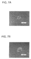
- FIGS. 7A and 7B are photographs showing impressions formed on respective surfaces of Samples 1 and 5 after a diamond identator has been forced onto the surfaces with a predetermined load.
- FIG. 1A is an elevational view of a diamond-coated body in the form of an end mill 10 which is constructed according to this invention.
- the end mill 10 includes a tool substrate (base material) 12 having a generally cylindrical shape and formed of a super-fine particle cemented carbide which includes WC as its main component and also Co such that a content of Co is 5-10 wt %.
- the super-fine particle cemented carbide includes a hard phase which is provided by particles having an average diameter or size of not larger than 1 ⁇ m.
- the tool substrate 12 has a cutting teeth portion 14 and a shank portion 15 which are formed integrally with each other.
- the cutting teeth portion 14 in which helical flutes and cutting teeth are formed, has a surface that is coated with a diamond coating 16 .
- FIG. 1A is an elevational view of a diamond-coated body in the form of an end mill 10 which is constructed according to this invention.
- the end mill 10 includes a tool substrate (base material) 12 having a generally cylindrical shape and formed
- the oblique-lined portion represents a portion of the surface on which the diamond coating 16 is coated.
- Each of the cutting teeth has a peripheral flank face, a bottom or end flank face and a rake face which is provided by the corresponding one of the helical flutes, so that a peripheral cutting edge and a bottom or end cutting edge are formed in each cutting tooth.
- the peripheral cutting edge is defined by an intersection of the rake face and the peripheral flank face, while the end cutting edge is defined by an intersection of the rake face and the end flank face.
- the end mill 10 further includes an interface layer 18 which is interposed between the tool substrate 12 and the diamond coating 16 .
- the interface layer 18 is held in contact in its inner and outer surfaces with the tool substrate 12 and the diamond coating 16 , respectively, as shown in FIG. 1B which is a cross sectional view of a radially outer portion of the cutting teeth portion 14 of the end mill 10 .
- FIG. 2 is a flow chart illustrating a procedure for manufacturing the end mill 10 .
- the manufacturing procedure is initiated with a substrate preparing step S 1 in which a super-fine particle cemented carbide bar is subjected to a grinding operation and/or other machining operation for forming the tool substrate 12 .
- a surface roughening step S 2 is then implemented to roughen the surface of the cutting teeth portion 14 of the tool substrate 12 , for increasing a strength with which the interface layer 18 and the diamond coating 16 adhere to or are fixed to the tool substrate 12 .
- This surface roughening step S 2 is implemented, for example, by an electrolytic polishing or other chemical corrosion treatment, or by a sandblasting with suitable abrasive grains, such that the roughened surface has a roughness curve whose maximum height Ry is held within a range from 0.5 ⁇ m to 2 ⁇ m.
- An interface-layer forming step S 3 is then implemented to form the interface layer 18 , which is provided by TiAlN, on the roughened surface of the cutting teeth portion 14 of the tool substrate 12 in accordance with an ion plating method or other PVD method, without an acid treatment or other treatment for removing Co from the tool substrate 12 .
- the formation of the interface layer 18 is carried out at a raised temperature of 400-500° C. However, this temperature is lower than a temperature of 700-1000° C. at which the formation of the diamond coating is carried out.
- the surface of the cutting teeth portion 14 is bombarded with generated ions which collide with the surface of the cutting teeth portion 14 .
- the interface layer 18 is formed such that the interface layer 18 has a predetermined thickness, for example, of about 2-5 ⁇ m.
- the thickness of the interface layer 18 is predetermined on the basis of a degree of the surface roughness of the tool substrate 12 such that the pits and projections formed in the surface of the tool substrate 12 cause the outer surface of the interface layer 18 to have pits and projections which provide a suitable degree of surface roughness, as shown in FIG. 1 B.
- the interface-layer forming step S 3 is followed by a diamond-coating forming step S 4 in which diamond particles are formed and grown on the outer surface of the interface layer 18 by using a microwave plasma CVD device 20 as shown in FIG. 3, so that the interface layer 18 is coated with the diamond coating 16 .
- the diamond coating 16 is formed to have a predetermined thickness, for example, of about 5-15 ⁇ m, which enables the diamond coating 16 to have a required degree of wear resistance.
- the diamond coating 16 is bonded or fixed to the interface layer 18 with a strength increased by the pits and projections and also droplets (relatively small pits and projections) formed on the outer surface of the interface layer 18 . That is, the diamond coating 16 is fixed to the interface layer 18 or the tool substrate 12 with the sufficiently strength, without necessity of provision of a layer of a non-crystalline carbonized structure between the interface layer 18 and the diamond coating 16 .
- the microwave plasma CVD device 20 of FIG. 3 includes a tubular furnace or reactor 22 , a microwave generator 24 , a gas supplier 26 , a vacuum pump 28 and an electromagnetic coil 30 .
- the device 20 further includes a table 32 which is disposed in the tubular reactor 22 , and a supporting member 36 which is disposed on the table 32 .
- a plurality of tool substrates 12 are supported by the supporting member 36 such that the cutting teeth portion 14 of each tool substrate 12 which is to be coated with the diamond coating 16 is positioned upwardly of the shank portion 15 .
- the microwave generator 24 serves to generate, for example, a microwave having a frequency of about 2.45 GHz.
- Each tool substrate 12 is heated with introduction of the microwave into the reactor 22 , and a temperature at the surface of the cutting tooth portion 14 of the heated substrate 12 is detected by a radiation thermometer which is provided in an observation window 38 formed through an upper wall of the tubular reactor 22 .
- An electric power supplied to the microwave generator 24 is controlled in a feedback manner, i.e., on the basis of a signal representative of the detected temperature, such that the detected temperature coincides with a predetermined temperature.
- a silica glass plate 40 is provided in an upper portion of the tubular reactor 22 , so that the tool substrates 12 can be observed through the glass plate 40 , and a vacuum state within the tubular reactor 22 established by the vacuum pump 28 can be maintained by the glass plate 40 .
- the gas supplier 26 serves to supply a material gas such as methane (CH 4 ), hydrogen (H 2 ) and carbon monoxide (CO) into the tubular reactor 22 .
- the gas suppliers 26 includes a gas cylinder which is filled with the material gas, a flow control valve which serves to control a flow rate of the material gas, and a flowmeter which serves to measure the flow rate of the material gas.
- the vacuum pump 28 serves to reduce the pressure in the interior of the reactor 22 , by sucking the gas in the interior of the reactor 22 .
- An electric current supplied to the a motor of the vacuum pump 28 is controlled in a feedback manner such that an actual value of the pressure detected by a pressure gage 42 coincides with a predetermined value.
- the electromagnetic coil 30 consists of an annular mass which is positioned radially outwardly of the tubular reactor 22 so as to surround the outer circumferential surface of the reactor 22 .
- the diamond-coating forming step S 4 consists of a nucleus bonding step and a crystal growing step.
- the flow rates of the methane and hydrogen are controlled to be respective predetermined values, while the microwave generator 24 is controlled such that the temperature at the surface of the tool substrate 12 coincides with a predetermined value which may range from 700° C. to 900° C.
- the vacuum pump 28 is activated such that the pressure in the reactor 22 coincides with a predetermined value which may range from 2.7 ⁇ 10 2 Pa to 2.7 ⁇ 10 3 Pa.
- nucleus layer used in this specification may be interpreted to mean a layer consisting of an aggregation of a multiplicity of nucleuses.
- the nucleus bonding step is followed by the crystal growing step in which the flow rates of the methane and hydrogen are controlled such that the concentration of the methane in the supplied gas coincides with a predetermined value which may range from 1% to 4%.
- the microwave generator 24 is controlled such that the temperature at the outer surface of the interface layer 18 coincides with a predetermined value which may range from 800° C. to 900° C.
- the vacuum pump 28 is activated such that the pressure in the reactor 22 coincides with a predetermined value which may range from 1.3 ⁇ 10 3 Pa to 6.7 ⁇ 10 3 Pa.
- the concentration of the methane, the temperature of the outer surface of the interface layer 18 and the pressure in the tubular reactor 22 are held in the respective predetermined values for a predetermined time, whereby the diamond crystals are grown from the nucleus layer, for forming the diamond coating 16 having a predetermined thickness.
- the diamond coating 16 can be adapted to consist of a plurality of layers each formed of grown diamond crystallites, by repeatedly implementing the nucleus bonding step and the crystal growing step.
- the interface layer 18 consisting of TiAlN is provided to be disposed on the roughened surface of the tool substrate 12 , and the interface layer 18 is coated with the diamond coating 16 .
- the diamond coating 16 can be fixed to the tool substrate 12 through the interface layer 18 with a sufficiently large fixing strength, in spite of the absence of a layer consisting of a non-crystalline carbonized structure. This arrangement contributes to simplification of the construction of the end mill 10 and accordingly reduction of the cost of manufacture of the end mill 10 .
- the fixing strength is increased owing to what are called “droplets”, i.e., small pits and projections which are likely to be formed in the outer surface of the interface layer 18 , for example, where the interface layer 18 is formed of TiAlN in accordance with a physical vapor deposition (PVD) method. That is, the droplets cooperate with the roughened surface of the tool substrate 12 , for increasing an area of the outer surface of the interface layer 18 which can be held in contact with the diamond coating 16 and for enabling the interface layer 18 to mesh in its pits and projections with the diamond coating 16 .
- droplets i.e., small pits and projections which are likely to be formed in the outer surface of the interface layer 18 , for example, where the interface layer 18 is formed of TiAlN in accordance with a physical vapor deposition (PVD) method. That is, the droplets cooperate with the roughened surface of the tool substrate 12 , for increasing an area of the outer surface of the interface layer 18 which can be held in contact with the diamond coating 16 and
- the interface layer 18 interposed between the tool substrate 12 and the diamond coating 16 further contributes to prevent Co, contained in the tool substrate 12 , from being separated from the tool substrate 12 during the formations of the interface layer 18 and the diamond coating 16 , avoiding a risk of reduction in the fixing strength with which the diamond coating 16 is fixed to the interface layer 18 and the tool substrate 12 , and accordingly making it possible to eliminate an acid treatment or other treatment for removing Co from the tool substrate 12 , prior to the formation of the diamond coating 16 .
- the interface layer 18 and the diamond coating 16 can be fixed to the tool substrate 12 with the sufficiently high fixing strength, not only where the tool substrate 12 is made of the ordinary cemented carbide but also where the tool substrate 12 is made of the super-fine particle cemented carbide having a high Co content.
- the super-fine particle cemented carbide can be used as a material for forming the tool substrate 12 , so that the end mill 10 can be advantageously used to machine or cut a workpiece made of a hard material such as a cast iron and an aluminum alloy casting containing high silicon, with its remarkably improved durability owing to a high degree of wear resistance of the diamond coating 16 and a high degree of unbrittleness of the tool substrate 12 formed of the super-fine particle cemented carbide.
- each of Samples 1 , 2 and 6 had a tool substrate formed of a super-fine particle cemented carbide, while each of Samples 3 , 4 and 5 had a tool substrate formed of an ordinary cemented carbide.
- Each of Samples 1 - 4 included a diamond coating and an interface layer which was interposed between the tool substrate and the diamond coating and which was formed of TiAlN, while each of Samples 5 and 6 did not include an interface layer so that the diamond coating was disposed directly on the tool substrate.
- the surface of the tool substrate was roughed by an electrolytic polishing or a sandblasting with abrasive grains made of SiC, prior to the formations of the interface layer and the diamond coating.
- each of Samples 5 and 6 the surface of the tool substrate was roughed by an electrolytic polishing and then subjected to an acid treatment for removing Co from the tool substrate, prior to the formation of the diamond coating.
- the thickness of the diamond coating of each of Samples 1 - 3 , 5 and 6 was 10 ⁇ m, while that of Sample 4 was 14 ⁇ m.
- the diameter of the cutting teeth portion of each of Samples 1 - 6 was 10 mm.
- Samples 1 and 4 remained still serviceable even after the cutting of the side face of ADC12 through the distance of 65 m, while Samples 2 , 3 , 5 and 6 became unserviceable due to removals of the diamond coatings from the tool substrates when the above-described accumulative distances of Samples 2 , 3 , 5 and 6 amounted to 30 m, 37 m, 44 m and 23 m, respectively, as indicated by the graph of FIG. 6 .
- Sample 1 constructed according to the present invention exhibited a durability that was improved by at least about 50% over that of Sample 5 in which the ordinary cemented carbide substrate was subjected to the Co removing treatment (acid treatment) and then coated with the diamond coating.
- the provision of the interface layer is effective to bond or fix to the tool substrate with a sufficiently high strength even where the substrate is made of the super-fine particle cemented carbide.
- a suitable thickness of the diamond coating is effective to further improve the service life of the tool.
- FIGS. 7A and 7B are photographs showing impressions or indentations which result in local removals of diamond coatings of Samples 1 and 5 , respectively, after the diamond indentator was forced onto the surfaces of these Samples.
- the indentation formed on the surface of Sample 1 was smaller than that formed on the surface of Sample 5 . That is, Sample 1 exhibited a higher fixing strength of the diamond coating to the tool substrate, than that of Sample 5 .
Landscapes
- Chemical & Material Sciences (AREA)
- Engineering & Computer Science (AREA)
- Mechanical Engineering (AREA)
- Metallurgy (AREA)
- Chemical Kinetics & Catalysis (AREA)
- Materials Engineering (AREA)
- General Chemical & Material Sciences (AREA)
- Organic Chemistry (AREA)
- Inorganic Chemistry (AREA)
- Cutting Tools, Boring Holders, And Turrets (AREA)
- Chemical Vapour Deposition (AREA)
- Crystals, And After-Treatments Of Crystals (AREA)
- Physical Vapour Deposition (AREA)
Applications Claiming Priority (2)
| Application Number | Priority Date | Filing Date | Title |
|---|---|---|---|
| JP2000-375918 | 2000-12-11 | ||
| JP2000375918A JP3590579B2 (ja) | 2000-12-11 | 2000-12-11 | ダイヤモンド被覆部材およびその製造方法 |
Publications (2)
| Publication Number | Publication Date |
|---|---|
| US20020071949A1 US20020071949A1 (en) | 2002-06-13 |
| US6656591B2 true US6656591B2 (en) | 2003-12-02 |
Family
ID=18844854
Family Applications (1)
| Application Number | Title | Priority Date | Filing Date |
|---|---|---|---|
| US09/960,375 Expired - Fee Related US6656591B2 (en) | 2000-12-11 | 2001-09-24 | Diamond-coated body including interface layer interposed between substrate and diamond coating, and method of manufacturing the same |
Country Status (4)
| Country | Link |
|---|---|
| US (1) | US6656591B2 (de) |
| JP (1) | JP3590579B2 (de) |
| KR (1) | KR100706583B1 (de) |
| DE (1) | DE10150413B4 (de) |
Cited By (6)
| Publication number | Priority date | Publication date | Assignee | Title |
|---|---|---|---|---|
| US20090226715A1 (en) * | 2008-03-04 | 2009-09-10 | Gm Global Technology Operations, Inc. | Coated article and method of making the same |
| US20100108403A1 (en) * | 2008-11-06 | 2010-05-06 | Smith International, Inc. | Surface coatings on cutting elements |
| US20110171463A1 (en) * | 2010-01-14 | 2011-07-14 | Andreas Christian Hohle | Vanadium-based hard material coating of a wind power plant component |
| WO2012088571A1 (en) * | 2010-12-27 | 2012-07-05 | Whirpool S.A. | Piston assembly for alernative compressor |
| US20120276826A1 (en) * | 2011-03-01 | 2012-11-01 | GFD Gesellschaft für Diamantprodukte mbH. | Cutting tool with blade made of fine-crystalline diamond |
| US20130017412A1 (en) * | 2010-05-31 | 2013-01-17 | Jtekt Corporation | Covered member and process for production thereof |
Families Citing this family (23)
| Publication number | Priority date | Publication date | Assignee | Title |
|---|---|---|---|---|
| US7866342B2 (en) | 2002-12-18 | 2011-01-11 | Vapor Technologies, Inc. | Valve component for faucet |
| US8555921B2 (en) | 2002-12-18 | 2013-10-15 | Vapor Technologies Inc. | Faucet component with coating |
| US7866343B2 (en) | 2002-12-18 | 2011-01-11 | Masco Corporation Of Indiana | Faucet |
| US8220489B2 (en) | 2002-12-18 | 2012-07-17 | Vapor Technologies Inc. | Faucet with wear-resistant valve component |
| US7131365B2 (en) * | 2003-09-16 | 2006-11-07 | Irwin Industrial Tool Company | Multi-chip facet cutting saw blade and related method |
| US7077918B2 (en) | 2004-01-29 | 2006-07-18 | Unaxis Balzers Ltd. | Stripping apparatus and method for removal of coatings on metal surfaces |
| CH705281B1 (de) * | 2004-01-29 | 2013-01-31 | Oerlikon Trading Ag | Entschichtungsverfahren. |
| WO2005073433A1 (de) * | 2004-01-29 | 2005-08-11 | Unaxis Balzers Ag | Entschichtungsverfahren und einkammeranlage zur durchführung des entschichtungsverfahrens |
| US20060147631A1 (en) * | 2005-01-04 | 2006-07-06 | Lev Leonid C | Method for making diamond coated substrates, articles made therefrom, and method of drilling |
| EP1944110B1 (de) * | 2007-01-15 | 2012-11-07 | Fraisa Holding AG | Verfahren zur Behandlung und Bearbeitung von Werkzeugen zur spanabhebenden Bearbeitung von Werkstücken |
| AT506133B1 (de) * | 2007-11-16 | 2009-11-15 | Boehlerit Gmbh & Co Kg | Reibrührschweisswerkzeug |
| WO2011135100A1 (de) * | 2010-04-30 | 2011-11-03 | Cemecon Ag | Beschichteter körper sowie ein verfahren zur beschichtung eines körpers |
| GB2483475B (en) * | 2010-09-08 | 2015-08-05 | Dormer Tools Ltd | Bore cutting tool and method of making the same |
| JP5286626B2 (ja) * | 2011-01-31 | 2013-09-11 | 住友電工ハードメタル株式会社 | 表面被覆切削工具およびその製造方法 |
| JP5286625B2 (ja) * | 2011-01-31 | 2013-09-11 | 住友電工ハードメタル株式会社 | 表面被覆切削工具およびその製造方法 |
| JP5982606B2 (ja) | 2011-12-05 | 2016-08-31 | 学校法人慶應義塾 | ダイヤモンド被膜被着部材およびその製造方法 |
| JP5974940B2 (ja) * | 2013-03-14 | 2016-08-23 | 三菱マテリアル株式会社 | 交換式切削ヘッド |
| JP5974954B2 (ja) * | 2013-03-29 | 2016-08-23 | 三菱マテリアル株式会社 | ラフィングエンドミル |
| JP6544859B2 (ja) * | 2013-08-30 | 2019-07-17 | 兼房株式会社 | カッターの替刃 |
| US11090739B2 (en) * | 2015-12-14 | 2021-08-17 | Alp Havacilik Sanayi Ve Ticaret Anonim Sirketi | End-mills made of hard metal and ceramic combined by brazing method |
| CN110055378B (zh) * | 2019-05-17 | 2023-04-21 | 东台艺新金属材料有限公司 | 锯条的回火工艺 |
| CN110629194B (zh) * | 2019-10-31 | 2021-11-02 | 浙江工业大学 | 一种以Cr/CrAlN为过渡层在不锈钢表面制备金刚石薄膜的方法 |
| CN114686803B (zh) * | 2022-03-22 | 2023-03-17 | 武汉理工大学 | 一种微波等离子体化学气相沉积制备的三元氮化物涂层及其方法 |
Citations (11)
| Publication number | Priority date | Publication date | Assignee | Title |
|---|---|---|---|---|
| JPS627267A (ja) | 1985-07-03 | 1987-01-14 | Konishiroku Photo Ind Co Ltd | 網点形成方法 |
| JPH04503822A (ja) * | 1990-03-12 | 1992-07-09 | アクチエボラゲツト・アストラ | 改良された合成方法 |
| JPH0578845A (ja) | 1991-09-19 | 1993-03-30 | Toshiba Tungaloy Co Ltd | 高密着性ダイヤモンド被覆焼結合金 |
| JPH05230656A (ja) | 1992-02-19 | 1993-09-07 | Idemitsu Petrochem Co Ltd | ダイヤモンド被覆部材の製造方法 |
| JPH05263251A (ja) | 1992-03-16 | 1993-10-12 | Seiko Instr Inc | 被覆焼結体 |
| JPH05279855A (ja) | 1992-04-01 | 1993-10-26 | Mitsubishi Materials Corp | 人工ダイヤモンド層の密着性にすぐれた表面被覆炭化タングステン基超硬合金製切削工具 |
| JPH06951A (ja) | 1992-06-18 | 1994-01-11 | Dainippon Printing Co Ltd | 印刷精度測定マーク |
| JPH06346241A (ja) | 1993-06-14 | 1994-12-20 | Sumitomo Electric Ind Ltd | ダイヤモンド被覆材料およびその製造方法 |
| JPH07108404A (ja) | 1993-10-13 | 1995-04-25 | Mitsubishi Materials Corp | 表面被覆切削工具 |
| JPH08232067A (ja) | 1995-02-27 | 1996-09-10 | Hitachi Tool Eng Ltd | 強度に優れた硬質炭素膜被覆部材 |
| JPH11510858A (ja) | 1995-08-11 | 1999-09-21 | クレドー・ツール・カンパニー | 化学蒸着法によるダイヤモンド薄膜で被覆するための超硬合金支持体の処理 |
Family Cites Families (9)
| Publication number | Priority date | Publication date | Assignee | Title |
|---|---|---|---|---|
| JPS6173882A (ja) * | 1984-09-17 | 1986-04-16 | Sumitomo Electric Ind Ltd | 超硬質層被覆材料 |
| US4764434A (en) * | 1987-06-26 | 1988-08-16 | Sandvik Aktiebolag | Diamond tools for rock drilling and machining |
| JPH06248422A (ja) * | 1993-02-26 | 1994-09-06 | Seiko Instr Inc | 被覆焼結体およびその製造方法 |
| EP0627498B1 (de) * | 1993-05-25 | 2000-08-09 | Ngk Spark Plug Co., Ltd | Substrat auf Keramikbasis und Verfahren zu dessen Herstellung |
| US5688557A (en) * | 1995-06-07 | 1997-11-18 | Lemelson; Jerome H. | Method of depositing synthetic diamond coatings with intermediates bonding layers |
| US5722803A (en) * | 1995-07-14 | 1998-03-03 | Kennametal Inc. | Cutting tool and method of making the cutting tool |
| EP1067210A3 (de) * | 1996-09-06 | 2002-11-13 | Sanyo Electric Co., Ltd. | Verfahren zur Abscheidung eines harten Kohlenstoff-Filmes auf einem Substrat und Klinge für einen elektrischen Rasierer |
| JP3372493B2 (ja) * | 1998-12-09 | 2003-02-04 | 株式会社不二越 | 硬質炭素系被膜を有する工具部材 |
| JP5792968B2 (ja) * | 2011-02-28 | 2015-10-14 | 日本バイリーン株式会社 | フロアマット |
-
2000
- 2000-12-11 JP JP2000375918A patent/JP3590579B2/ja not_active Expired - Fee Related
-
2001
- 2001-09-24 US US09/960,375 patent/US6656591B2/en not_active Expired - Fee Related
- 2001-10-11 DE DE10150413.6A patent/DE10150413B4/de not_active Expired - Fee Related
- 2001-10-29 KR KR1020010066733A patent/KR100706583B1/ko not_active IP Right Cessation
Patent Citations (11)
| Publication number | Priority date | Publication date | Assignee | Title |
|---|---|---|---|---|
| JPS627267A (ja) | 1985-07-03 | 1987-01-14 | Konishiroku Photo Ind Co Ltd | 網点形成方法 |
| JPH04503822A (ja) * | 1990-03-12 | 1992-07-09 | アクチエボラゲツト・アストラ | 改良された合成方法 |
| JPH0578845A (ja) | 1991-09-19 | 1993-03-30 | Toshiba Tungaloy Co Ltd | 高密着性ダイヤモンド被覆焼結合金 |
| JPH05230656A (ja) | 1992-02-19 | 1993-09-07 | Idemitsu Petrochem Co Ltd | ダイヤモンド被覆部材の製造方法 |
| JPH05263251A (ja) | 1992-03-16 | 1993-10-12 | Seiko Instr Inc | 被覆焼結体 |
| JPH05279855A (ja) | 1992-04-01 | 1993-10-26 | Mitsubishi Materials Corp | 人工ダイヤモンド層の密着性にすぐれた表面被覆炭化タングステン基超硬合金製切削工具 |
| JPH06951A (ja) | 1992-06-18 | 1994-01-11 | Dainippon Printing Co Ltd | 印刷精度測定マーク |
| JPH06346241A (ja) | 1993-06-14 | 1994-12-20 | Sumitomo Electric Ind Ltd | ダイヤモンド被覆材料およびその製造方法 |
| JPH07108404A (ja) | 1993-10-13 | 1995-04-25 | Mitsubishi Materials Corp | 表面被覆切削工具 |
| JPH08232067A (ja) | 1995-02-27 | 1996-09-10 | Hitachi Tool Eng Ltd | 強度に優れた硬質炭素膜被覆部材 |
| JPH11510858A (ja) | 1995-08-11 | 1999-09-21 | クレドー・ツール・カンパニー | 化学蒸着法によるダイヤモンド薄膜で被覆するための超硬合金支持体の処理 |
Non-Patent Citations (5)
| Title |
|---|
| "Adhesion of Diamond Film To Substrate" Toshiba Review; vol. 46, No. 1; 1991; pp. 72-74. |
| "Diamond Nucleation And Growth Of Different Cutting Tool Materials: Influence Of Substrate Pre-Treatments" by E. Cappelli et al.; Diamond and Related Materials 5; 1996; pp. 292-298. |
| "Morphologies And Adhesion Strength Of Diamond Films Deposited On WC-6% Co Cemented Carbides With Different Surface Characteristics" by Peng XiLing et al.; Thin Solid Films, 239; 1994; pp. 47-50. |
| English abstract of JP 58-126972.* * |
| English abstract of JP 62-196371.* * |
Cited By (9)
| Publication number | Priority date | Publication date | Assignee | Title |
|---|---|---|---|---|
| US20090226715A1 (en) * | 2008-03-04 | 2009-09-10 | Gm Global Technology Operations, Inc. | Coated article and method of making the same |
| US20100108403A1 (en) * | 2008-11-06 | 2010-05-06 | Smith International, Inc. | Surface coatings on cutting elements |
| US8414986B2 (en) * | 2008-11-06 | 2013-04-09 | Smith International, Inc. | Method of forming surface coatings on cutting elements |
| US20110171463A1 (en) * | 2010-01-14 | 2011-07-14 | Andreas Christian Hohle | Vanadium-based hard material coating of a wind power plant component |
| US20130017412A1 (en) * | 2010-05-31 | 2013-01-17 | Jtekt Corporation | Covered member and process for production thereof |
| US8951640B2 (en) * | 2010-05-31 | 2015-02-10 | Jtekt Corporation | Covered member and process for production thereof |
| WO2012088571A1 (en) * | 2010-12-27 | 2012-07-05 | Whirpool S.A. | Piston assembly for alernative compressor |
| US20120276826A1 (en) * | 2011-03-01 | 2012-11-01 | GFD Gesellschaft für Diamantprodukte mbH. | Cutting tool with blade made of fine-crystalline diamond |
| US8904650B2 (en) * | 2011-03-01 | 2014-12-09 | Gfd Gesellschaft Für Diamantprodukte Mbh | Cutting tool with blade made of fine-crystalline diamond |
Also Published As
| Publication number | Publication date |
|---|---|
| JP3590579B2 (ja) | 2004-11-17 |
| DE10150413A1 (de) | 2002-06-13 |
| KR100706583B1 (ko) | 2007-04-11 |
| DE10150413B4 (de) | 2017-05-11 |
| JP2002179493A (ja) | 2002-06-26 |
| KR20020046925A (ko) | 2002-06-21 |
| US20020071949A1 (en) | 2002-06-13 |
Similar Documents
| Publication | Publication Date | Title |
|---|---|---|
| US6656591B2 (en) | Diamond-coated body including interface layer interposed between substrate and diamond coating, and method of manufacturing the same | |
| KR101065572B1 (ko) | 다이아몬드 막 피복 공구 및 그 제조 방법 | |
| US6547494B2 (en) | Diamond coated tool and method of manufacturing the diamond coated tool | |
| JP5111379B2 (ja) | 切削工具及びその製造方法並びに切削方法 | |
| EP0503822B2 (de) | Ein diamantbeschichteter und/oder mit diamantartigem Kohlenstoff beschichteter Hartstoff | |
| JP2007001007A (ja) | 硬化鋼の仕上げ用複合被膜 | |
| JP2001502246A (ja) | 切削工具 | |
| US20150017468A1 (en) | Coated tool and methods of making and using the coated tool | |
| US20030039520A1 (en) | Cutting tool coated with diamond | |
| JP2001504550A (ja) | ダイヤモンド被覆された部材の製造方法 | |
| JP3379150B2 (ja) | ダイヤモンド被覆材料およびその製造方法 | |
| JPH1158106A (ja) | ダイヤモンドコーティング切削工具及びその製造方法 | |
| JP5321360B2 (ja) | 表面被覆切削工具 | |
| JP4845490B2 (ja) | 表面被覆切削工具 | |
| JP2003225809A (ja) | 難削材の高速切削ですぐれた耐摩耗性を発揮する表面被覆超硬合金製切削工具 | |
| JP2004074302A (ja) | 重切削条件で硬質被覆層がすぐれた耐チッピング性を発揮する表面被覆超硬合金製切削工具 | |
| JP2004074378A (ja) | 高速切削加工で硬質被覆層がすぐれた耐摩耗性を発揮する表面被覆超硬合金製切削工具 | |
| JP3174464B2 (ja) | 気相合成ダイヤモンド被覆焼結体 | |
| JP2004074300A (ja) | 高速切削条件で硬質被覆層がすぐれた耐摩耗性を発揮する表面被覆超硬合金製切削工具 | |
| JP2002254210A (ja) | 重切削ですぐれた耐摩耗性を発揮する表面被覆超硬合金製切削工具 | |
| JP2006247779A (ja) | 被覆cBN基焼結体切削工具 | |
| JPH08311652A (ja) | ダイヤモンド被覆超硬合金工具およびその製造方法 | |
| JP3900526B2 (ja) | 高速重切削条件で硬質被覆層がすぐれた耐摩耗性を発揮する表面被覆超硬合金製切削工具 | |
| JP2004154878A (ja) | 高速重切削条件で硬質被覆層がすぐれた耐摩耗性を発揮する表面被覆超硬合金製切削工具 | |
| JP2007130741A (ja) | 難削材の重切削加工で硬質被覆層がすぐれた耐チッピング性を発揮する表面被覆超硬切削工具 |
Legal Events
| Date | Code | Title | Description |
|---|---|---|---|
| AS | Assignment |
Owner name: OSG CORPORATION, JAPAN Free format text: ASSIGNMENT OF ASSIGNORS INTEREST;ASSIGNORS:LIU, HAO;MURAKAMI, YOSHIHIKO;HANYU, HIROYUKI;REEL/FRAME:012209/0358 Effective date: 20010406 |
|
| FPAY | Fee payment |
Year of fee payment: 4 |
|
| FPAY | Fee payment |
Year of fee payment: 8 |
|
| REMI | Maintenance fee reminder mailed | ||
| LAPS | Lapse for failure to pay maintenance fees | ||
| STCH | Information on status: patent discontinuation |
Free format text: PATENT EXPIRED DUE TO NONPAYMENT OF MAINTENANCE FEES UNDER 37 CFR 1.362 |
|
| FP | Lapsed due to failure to pay maintenance fee |
Effective date: 20151202 |