US6587380B2 - Programming method for non-volatile semiconductor memory device - Google Patents
Programming method for non-volatile semiconductor memory device Download PDFInfo
- Publication number
- US6587380B2 US6587380B2 US09/955,158 US95515801A US6587380B2 US 6587380 B2 US6587380 B2 US 6587380B2 US 95515801 A US95515801 A US 95515801A US 6587380 B2 US6587380 B2 US 6587380B2
- Authority
- US
- United States
- Prior art keywords
- memory cell
- twin
- voltage
- programming
- control gate
- Prior art date
- Legal status (The legal status is an assumption and is not a legal conclusion. Google has not performed a legal analysis and makes no representation as to the accuracy of the status listed.)
- Expired - Fee Related
Links
Images


Classifications
-
- G—PHYSICS
- G11—INFORMATION STORAGE
- G11C—STATIC STORES
- G11C16/00—Erasable programmable read-only memories
- G11C16/02—Erasable programmable read-only memories electrically programmable
- G11C16/06—Auxiliary circuits, e.g. for writing into memory
- G11C16/10—Programming or data input circuits
-
- G—PHYSICS
- G11—INFORMATION STORAGE
- G11C—STATIC STORES
- G11C16/00—Erasable programmable read-only memories
- G11C16/02—Erasable programmable read-only memories electrically programmable
- G11C16/04—Erasable programmable read-only memories electrically programmable using variable threshold transistors, e.g. FAMOS
- G11C16/0466—Erasable programmable read-only memories electrically programmable using variable threshold transistors, e.g. FAMOS comprising cells with charge storage in an insulating layer, e.g. metal-nitride-oxide-silicon [MNOS], silicon-oxide-nitride-oxide-silicon [SONOS]
- G11C16/0475—Erasable programmable read-only memories electrically programmable using variable threshold transistors, e.g. FAMOS comprising cells with charge storage in an insulating layer, e.g. metal-nitride-oxide-silicon [MNOS], silicon-oxide-nitride-oxide-silicon [SONOS] comprising two or more independent storage sites which store independent data
Definitions
- the present invention relates to a programming method for a non-volatile semiconductor memory device formed from twin memory cells each being equipped with one word gate and two non-volatile memory elements controlled by two control gates.
- MONOS Metal-Oxide-Nitride-Oxide-semiconductor or -substrate
- a gate dielectric layer between a channel and a gate is formed from a stacked body including a silicon oxide film, a silicon nitride film, and a silicon oxide film, and charge is trapped in the silicon nitride film.
- a MONOS type non-volatile semiconductor memory device is described in a reference (Y. Hayashi, et al. 2000 Symposium on VLSI Technology, Digest of Technical Papers, p. 122-p. 123).
- the reference describes a twin MONOS flash memory cell equipped with one word gate and two non-volatile memory elements (MONOS memory elements) controlled by two control gates.
- MONOS memory elements non-volatile memory elements
- a plurality of twin MONOS flash memory cells each having the structure described above are arranged in the row direction and the column direction in multiple rows and columns to form a memory cell array region.
- Two bit lines, one word line, and two control gate lines are required to drive a MONOS flash memory cell. However, when driving a plurality of twin memory cells, these lines can be commonly connected for different control gates if they are set at the same potential.
- Operations of this type of flash memory include erasing, programming, and reading data. Normally, data programming or data reading is performed at selected cells in units of 8 bits or 16 bits simultaneously.
- twin MONOS flash memory a plurality of twin MONOS flash memory cells that are not mutually isolated are connected to one word line.
- selected non-volatile memory element not only must the voltage of a twin MONOS flash memory including the selected cell be appropriately set, but also the voltage of an adjacent twin MONOS flash memory cell must be appropriately set.
- a programming method in which a plurality of twin memory cells, each having one word gate and first and second non-volatile memory elements controlled by first and second control gates, are arranged and, from among three adjacent twin memory cells (i ⁇ 1), (i), and (i+1) whose word gates are connected to one word line, data for the second non-volatile memory element of the twin memory cell (i) is programmed, comprises:
- a programming method in which a plurality of twin memory cells, each having one word gate and first and second non-volatile memory elements controlled by first and second control gates, are arranged and, from among three adjacent twin memory cells (i ⁇ 1), (i), and (i+1) whose word gates are connected to one word line, data for the first non-volatile memory element of the twin memory cell (i) is programmed, comprises:
- the programming word line selection voltage may preferably be set to a voltage that is high enough to be able to cause a current greater than a current provided by the constant current source to flow between a source and a drain (between bit lines) of the selected twin memory cell.
- the current that flows in the bit line during programming is also restricted at a constant level by the constant current source, such that the voltage for the bit line can be properly set and the programming operation can be securely performed.
- Each of the first and second non-volatile memory elements may include an ONO film formed from an oxide film (O), a nitride film (N), and an oxide film (O), which can be used as a charge trap site, but can have any other structure without being restricted to the structure described above.
- O oxide film
- N nitride film
- O oxide film
- FIG. 1 shows a cross section of a non-volatile semiconductor memory device in accordance with one embodiment of the present invention.
- FIG. 2A shows a plan layout of the non-volatile semiconductor memory device shown in FIG. 1 .
- FIG. 2B shows a plan view of two sector regions in FIG. 2 A.
- FIG. 2C shows a plan view of one memory block in FIG. 2 B.
- FIG. 2D shows a plan view of one large block in FIG. 2 C.
- FIG. 2E shows a plan view of one small block in FIG. 2 D.
- FIG. 3 schematically shows an illustration to be used to describe many small memory blocks and their wirings in one sector region shown in FIG. 2 B.
- FIG. 4 shows a circuit diagram of a small memory block shown in FIG. 3 .
- FIG. 5 shows a circuit diagram illustrating the relation between small memory blocks and control gate drivers shown in FIG. 3 .
- FIG. 6 schematically shows an illustration to be used to describe the relation between two memory blocks and local drivers in two adjacent sectors.
- FIG. 7 schematically shows an illustration to be used to describe a selected block an unselected opposite block opposing thereto, and other unselected blocks.
- FIG. 8 shows an equivalent circuit of the memory cells shown in FIG. 1 .
- FIG. 9 schematically shows an illustration to be used to describe a data reading operation in the non-volatile semiconductor memory device shown in FIG. 1 .
- FIG. 10 schematically shows an illustration to be used to describe voltages set in a selected block during data reading.
- FIG. 11 shows characteristic profiles indicating the relation between control gate voltages VCG and source-drain current Ids in the memory cell shown in FIG. 1 .
- FIG. 12 schematically shows an illustration to be used to describe set voltages in an unselected opposite block during data reading.
- FIG. 13 schematically shows an illustration to be used to describe set voltages in unselected blocks other than the opposite block during data reading.
- FIG. 14 schematically shows an illustration to be used to describe a data writing (programming) operation in the non-volatile semiconductor memory device shown in FIG. 1 .
- FIG. 15 schematically shows an illustration to be used to describe set voltages in a selected block during data programming.
- FIG. 16 schematically shows a circuit diagram of a Y path connected to the bit line.
- FIG. 17 schematically shows an illustration to be used to describe set voltages in an unselected opposite block during data programming.
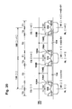
- FIG. 18 schematically shows an illustration to be used to describe set voltages in unselected blocks other than the opposite block during data programming.
- FIG. 19 schematically shows an illustration to be used to describe set voltages in a selected block during data programming with respect to memory elements on the selected side different from those shown in FIG. 15 .
- FIG. 20 schematically shows an illustration to be used to describe a data erasing operation in the non-volatile semiconductor memory device shown in FIG. 1 .
- FIG. 21 schematically shows an illustration to be used to describe set voltages in a selected block at the time of data erasing.
- FIG. 22 schematically shows an illustration to be used to describe set voltages in an unselected opposite block at the time of data erasing.
- FIG. 23 schematically shows an illustration to be used to describe set voltages in unselected blocks other than the opposite block at the time of data erasing.
- FIG. I shows a cross section of a non-volatile semiconductor memory device.
- one twin memory cell 100 includes a word gate 104 formed from a material including, for example, polycrystal silicon on a P-type well 102 with a gate oxide film therebetween, first and second control gates 106 A and 106 B, and first and second memory elements (MONOS memory elements) 108 A and 108 B.
- word gate 104 formed from a material including, for example, polycrystal silicon on a P-type well 102 with a gate oxide film therebetween
- first and second control gates 106 A and 106 B control gates 106 A and 106 B
- first and second memory elements (MONOS memory elements) 108 A and 108 B first and second memory elements
- the first and second control gates 106 A and 106 B are formed on both walls of the word gate 104 , and are electrically insulated from the word gate 104 .
- Each of the first and second memory elements 108 A and 108 B is formed by stacking layers of anoxide film (O), anitride film (N), and an oxide film (O) between one of the first and second control gates 106 A and 106 B that is formed from polycrystal silicon corresponding to the M (metal) of MONOS and the P-type well 102 . It is noted that the first and second control gates 106 A and 106 B can be formed from a conductive material such as silicide.
- one twin memory cell 100 has the first and second MONOS memory elements 108 A and 108 B equipped with split gates (the first and second control gates 106 A and 106 B) and the first and second MONOS memory elements 108 A and 108 B commonly use one word gate 104 .
- Each of the first and second MONOS memory elements 108 A and 108 B functions as a charge trap site.
- Each of the first and second MONOS memory elements 108 A and 108 B is capable of trapping charge at the ONO film 109 .
- a plurality of the word gates 104 are arranged at intervals in the row direction (a second direction B in FIG. 1) and are commonly connected to one word line WL that is formed from polycide.
- control gates 106 A and 106 B shown in FIG. 1 extend in the column direction (a first direction A perpendicular to the sheet surface of FIG. 1 ), and are commonly used by a plurality of the twin memory cells 100 that are arranged in the column direction. Accordingly, the elements 106 A and 106 B may also be referred to as control gate lines.
- control gate 106 B of the [i]-th twin memory cell 100 [i] and the control gate 106 A of the [i+1]-th twin memory cell 100 [i+1] are connected to a sub-control gate line SCG [i+1] that is formed from a metal layer provided above, for example, the word gate, the control gates, and the word lines.
- An [i+1]-th impurity layer 110 [i+1] that is commonly used by the MONOS memory element 108 B of the [i]-th twin memory cell 100 [i] and the MONOS memory element 108 A of the [i+1]-th twin memory cell 100 [i+1] is provided in the P-type well 102 .
- the impurity layers 110 [i], [i+1] and [i+2] are, for example, n-type impurity layers formed in a P-type well, extend in the column direction (in the first direction A perpendicular to the sheet surface of FIG. 1) and function as bit lines that are commonly used by the plurality of twin memory cells 100 that are arranged in the column direction. Accordingly, the elements 110 [i] , [i+1] and [i+2] are also referred to as bit lines BL[i], [i+1] and [i+2].
- FIG. 2A shows aplan layout of a single-chip non-volatile semiconductor memory device that includes a memory cell array region 200 and a global word line decoder 201 .
- the memory cell array region 200 includes, for example, a total of sixty-four sector regions 210 , namely 0 th to 63 rd sector regions.
- the sixty-four sector regions 210 are obtained by
- Each of the sector regions 210 has a longitudinal rectangular shape with its longitudinal direction being in the first direction (column direction) A.
- the minimum unit for erasing data is the sector region 210 , and data stored in the sector region 210 is erased in one lot or in a time-division manner.
- the memory cell array region 200 includes, for example, 4K word lines WL and 4K bit lines BL.
- 4K bit lines BL means a memory capacity of 8 Kbits.
- Each of the sector regions 210 has a memory capacity that is one sixty-fourth ( ⁇ fraction (1/64) ⁇ ) of the memory capacity of the entire memory, and a memory capacity defined by (4K word lines WL) ⁇ (64 bit lines BL) ⁇ 2.
- FIG. 2B shows in detail two adjacent ones ( 0 th and 1 st) of the sector regions 210 in the non-volatile semiconductor memory device shown in FIG. 2 A.
- local drivers 220 A and 220 B are disposed on both sides of the two sectors 210 .
- a sector control circuit 222 is disposed at, for example, an upper side of the two sectors 210 and the two local drivers 220 A and 220 B.
- Each of the sector regions 210 is divided in the second direction such that each has sixteen memory blocks (memory blocks corresponding to input/output bits) for I/O 0 to I/O 15 that enable reading and writing 16-bit data.
- Each of the memory blocks 214 has 4K ( 4096 ) word lines WL, as shown in FIG. 2 B.
- each one of the sector regions 210 shown in FIG. 2B is divided in the first direction A into eight large blocks 212 .
- Each of the large blocks 212 is divided in the first direction A into eight small blocks 215 , as shown in FIG. 2 D.
- Each of the small blocks 215 has sixty-four word lines WL, as shown in FIG. 2 E.
- FIG. 3 shows in detail the sector region 0 shown in FIG. 2 A.
- the small memory block 216 shown in FIG. 3 includes the twin memory cells 100 arranged in a matrix of, for example, sixty four in the column direction and, for example, four in the row direction.
- Each one of the small memory blocks 216 is connected to, for example, four sub-control gate lines SCG 0 to SCG 3 , four bit lines BL 0 to BL 3 that are data input and output lines, and sixty-four word lines WL.
- the even numbered sub-control gate lines SCG 0 and SCG 2 are commonly connected to the second control gates 106 B of the plurality of twin memory cells in an even numbered column (the 0th column or the 2nd column) and the first control gates 106 A of the plural twin memory cells in an odd numbered column (the 1st column or the 3rd column), respectively.
- the odd numbered sub-control gate lines SCG 1 and SCG 3 are commonly connected to the second control gates 106 B of the plurality of twin memory cells in an odd numbered column (the 1st column or the 3rd column) and the first control gates 106 A of the plural twin memory cells in an odd numbered column (the 2nd column or the 4th column), respectively.
- sixty-four small memory blocks 216 are arranged in the column direction in each one of the memory blocks 214 , and sixteen memory blocks 214 corresponding to sixteen I/O 0 to I/O 15 are arranged in the row direction for input and output of 16 bits.
- sixteen sub-control gate lines SCG 0 of the sixteen small memory blocks 216 arranged in the row direction are commonly connected to a main control gate line MCG 0 along the row direction.
- sixteen sub-control gate lines SCG 1 are commonly connected to a main control gate line MCG 1
- sixteen sub-control gate lines SCG 2 are commonly connected to a main control gate line MCG 2
- sixteen sub-control gate lines SCG 3 are commonly connected to a main control gate line MCG 3 .
- CG drivers 300 - 0 to 300 - 63 which are control gate driving sections for the sector region 0 , are provided.
- the CG drivers 300 are connected to the four main control gate lines MCG 0 to MCG 3 that extend in the row direction.
- FIG. 5 shows the relation between the sector region 0 and the sector region 1 that are mutually adjacent to each other,
- the sector region 0 and the sector region 1 commonly use the word line WL, but are provided with the main control gate line MCG and the main bit line MBL independently from one another.
- FIG. 5 shows the CG drivers 300 - 0 and 300 - 1 corresponding to the sector region 0 , and the CG drivers 301 - 0 and 301 - 1 corresponding to the sector region 1 , in which the CG drivers are independently provided for each of the sector regions.
- Each of the bit lines BL 0 (an impurity layer) disposed for each of the small memory blocks 216 is commonly connected to the main bit line MBL that is a metal wiring.
- the main bit line MBL is commonly used by the small memory blocks arranged in the column direction.
- a bit line selection gate 217 A is disposed in a path from the main bit line MBL to each bit line BL 0 in each of the small memory blocks. It is noted that the bit line selection gates 217 A are connected to the corresponding even numbered bit lines BL 0 , BL 2 , BL 4 , . . . , while bit line selection gates 217 B. although omitted in FIG. 5, are connected to the odd numbered bit lines BL 1 , BL 3 , BL 5 , . . . (see FIG. 10 and FIG. 15 ).
- FIG. 6 Two small blocks 215 in the 0 th and 1 st sector regions 210 that are adjacent to one another and the local drivers 220 A and 220 B on both sides thereof are shown in detail in FIG. 6 .
- four local control gate line drivers CGDRV 0 to CGDRV 3 corresponding to the CG drivers 300 shown in FIGS. 3 and 5 are provided in the local driver 220 A on the left side.
- four local control gate line drivers CGDRV 0 to CGDRV 3 corresponding to the CG drivers 301 shown in FIG. 5 are provided in the local driver 220 B on the right side
- WLDRV 62 for driving even numbered word lines WL 0 , 2 , . . . , 62 in the sectors 0 and 1 , and WLDRVR 0 for driving one redundant word line in the sector 0 are disposed in the local driver 220 A on the left.
- Local word line drivers WLDRV 1 , WLDRV 3 , . . . , WLDRV 63 for driving odd numbered word lines WL 1 , 3 , . . . , 63 in the sectors 0 and 1 , and WLDRVR 1 for driving one redundant word line in the sector 1 are disposed in the local driver 220 A on the right.
- a local bit line driver BSRV 0 for driving the bit line selection gate 217 A connected to, for example, the even numbered bit lines BL 0 and BL 2 in the sectors 0 and 1 is disposed in the local driver 220 A on the left side.
- a local bit line driver BSRV 1 for driving the bit line selection gate 217 B connected to, for example, the odd numbered bit lines BL 1 and BL 3 in the sectors 0 and 1 is disposed in the local driver 220 B on the right side.
- selected block selected Block
- unselected opposite block unselected opposite block
- unselected block unselected Block
- the unselected block means all of the small blocks 215 other than the selected block and the opposite block in the sectors 0 and 1 (including the sectors 2 to 63 ).
- Select Cell selected twin memory cell 100
- unselected Cell unselected twin memory cell 100
- memory element 108 A or 108 B on a selected side (Selected Side)
- Opposite Side an opposite side
- One twin memory cell 100 can be typified, as shown in FIG. 8, as having a transistor T 2 driven by the word gate 104 , and transistors T 1 and T 3 which are respectively driven by the first and second control gates 106 A and 106 B and which are serially connected to one another.
- FIG. 9 shows an illustration to be used to describe the case of reading data in a reverse mode from the MONOS memory element 108 B (selected cell) on the right side of the word gate 104 of the twin memory cell 100 [i] that is connected to the word line WL 1
- FIG. 10 shows voltages set at the selected block at that time.
- a read word line selection voltage Vdd (for example, 1.8 V) is applied to the word gate WL 1 that is present in the same row as the twin memory cell 100 [i], to thereby turn on the transistors T 2 on that row.
- an over-ride voltage (for example, 3 V) is applied through the sub-control gate line SCG[i] to the control gate 106 A on the left side (of an opposite cell) of the twin memory cell 100 [i] to thereby turn on the transistor T 1 that corresponds to the MONOS memory element 108 A.
- Aread voltage Vread (for example, 1.5 V) is applied as avoltage VCG of the control gate 106 B on the right side of the twin memory cell 100 [i].
- the transistor T 3 corresponding to the MONOS memory element 108 B operates differently, as follows.
- FIG. 11 shows the relation between voltages applied to the control gate 106 B on the right side (the selected cell side) of the twin memory cell 100 [i] and currents Ids that flow between the source and the drain of the transistor T 3 corresponding to the MONOS memory element 108 B (selected cell) controlled by the applied voltages.
- the voltage introduced which is applied to the control gate 106 B on the selected side when data is read, is set at a substantially intermediate voltage between the two threshold voltages Vlow and Vhigh.
- bit line BL[i] impurity layer 110 [i] connected to the opposite cell is connected to a sense amplifier, and potentials VD[i ⁇ 1], [i+1] and [i+2] on the other bit lines BL[i ⁇ 1], [i+1] and [i+2] are set to 0 V, respectively.
- the current Ids flows, and therefore, for example, a current of 25 ⁇ A or greater flows in the bit line BL[i] on the opposite side through the transistors T 1 and T 2 that are in ON state.
- bit lines BL[i] and [i+2] are connected to the bit line selection transistor (n-type MOS transistor) 217 A, and the bit lines BL[i ⁇ 1] and [i+1] are connected to the bit line selection transistor 217 B.
- the gate voltage of the bit line selection transistor 217 A is supplied through a step-up circuit (not shown) such that, for example, a voltage of 4.5 V is supplied to the bit line BL[i].
- the voltage on the source side of the MONOS memory element 108 A on the selected side becomes a voltage close to 0V (about several tens to one hundred mV).
- 0V about several tens to one hundred mV.
- This gate does not have to be supplied with 4.5 V, and therefore the load to the above-described step-up circuit (charge pump) can be reduced.
- the gate voltage of the bit line selection transistors 217 A and 217 B, the word lines WL, and the control gate lines CG are all set at 0 V. Since the bit line selection transistors 217 A and 217 B are turned OFF, the bit lines BL are in a floating state.
- FIG. 14 shows an illustration to be used to describe data programming for the MONOS memory element 108 B (selected cell) on the right side of the word gate 104 of the twin memory cell 100 [i] that is connected to the word line WL 1 .
- FIG. 15 shows voltages set in the selected block. Before the data programming operation, a data erasing operation to be described below is conducted.
- a potential on the sub-control gate line SCG[i] is an over-ride potential (for example, 2.5 V), which is the same as that shown in FIG. 9, and potentials on the sub-control gate lines SCG[i ⁇ 1] and [i+2] are at 0 V.
- the “over-ride potential” is a potential that is required to turn on the transistor T 1 corresponding to the MONOS memory element 108 A so that a program current flows without regard to the presence or the absence of programming of the MONOS memory element 108 A (element on the opposite side of the selected side element) on the left side of the twin memory cell 100 [i].
- a potential on the control gate 108 B (selected cell) on the right side of the twin memory cell 100 [i+1] is set through the sub-control gate line SCG[i+1] at a writing voltage Vwrite (for example, 5.5 V) shown in FIG. 4, which is a programming control gate voltage.
- FIG. 16 schematically shows the interior of a Y path circuit 400 that is connected to the bit my line BL.
- a first transistor 401 for connecting the bit line BL to a sense amplifier or a bit line driver, and a second transistor 402 for connecting the bit line BL to a path other than the above are provided in the Y path circuit 400 .
- Opposite signals YS 0 and /YS 0 are input to the gates of the first and second transistors 401 and 402 , respectively.
- a power supply voltage Vdd (1.8 V) and a constant current to source 404 that provides a constant current of, for example, 5 ⁇ A are provided for the source of the second transistor 402 through a switch 403 .
- the voltage VD[i+1] on the bit line BL[i+1] shown in FIG. 14 and FIG. 15 is connected to the bit line driver through the transistor 401 shown in FIG. 16, such that it is set at a programming bit line voltage, for example, at 5 V.
- bit line BL[i+2] is set at Vdd through the transistor 402 and the switch 403 shown in FIG. 16 .
- Both of the bit lines BL[i ⁇ 1] and [i] are connected to the constant current source 404 through the second transistor 402 and the switch 403 shown in FIG. 16 .
- the transistors T 1 and T 2 of the twin memory cell 100 [i] turn on, such that the current Ids flows toward the bit line BL[i] , and on the other hand, channel hot electrons (CHE) are trapped in the ONO film 109 of the MONOS memory element 108 B.
- CHE channel hot electrons
- the programming word line selection voltage may be set to about 0.77 V, to set the bit line BL[i] to be at 0 V.
- the programming word line selection voltage is raised to about 1 V to increase the source-drain current, the current that may flow in the bit line BL[i] during programming is restricted by the constant current source 404 .
- the voltage on the bit line BL[i] can be optimally set (in a range of 0 to 1 V, and at about 0.7 V in the present embodiment), and the programming operation can be optimally performed.
- the voltage on the bit line BL[i+2] is set to, for example, Vdd, instead of 0 V, to thereby reduce the potential difference between the source and the drain to prevent write-disturbance.
- the voltage on the bit line BL[i+2] may be set to a voltage exceeding 0 V, and may preferably be set equal to or greater than the word line selection voltage during programming. As a result, the transistor T 2 of the memory cell [i+1] becomes difficult to turn on, such that disturbance is also prevented.
- a voltage of 8 V is applied to the gate of the bit line selection transistor 217 B.
- a voltage of 8 V is likewise applied to the gate of the bit line selection transistor 217 B.
- the bit line BL[i+2] is required to be set to Vdd for the reasons described above, and therefore a high voltage higher than Vdd also needs to be applied to the gate of the transistor 217 A, a voltage of 8 V that is the same as the gate voltage of the transistor 217 B is used. It is noted that a gate voltage of the bit line selection transistor 217 A higher than Vdd+Vth may suffice.
- the gate voltage of the bit line selection transistors 217 A and 217 B, the word lines WL, and the control gate lines CG are all set at 0 V. Since the bit line selection transistors 217 A and 217 B are turned OFF, the bit lines BL are in a floating state.
- FIG. 20 schematically shows an illustration used to describe erasing data in all the memory cells in the sector 0 in one lot
- FIG. 21 shows the state of set voltages for memory cells in a part of the sector 0 .
- the potential of each of the word gates 104 is set to 0 V by the word line WL, and the potential of the control gates 106 A and 106 B is set at an erasing control gate line voltage that is, for example, about ⁇ 1 to ⁇ 3 V by the sub-control gate lines SCG[i ⁇ 1], [i], [i+1], and [i+2]. Furthermore, the potential of each of the bit lines BL[i ⁇ 1], [i], [i+1], and [i+2] is set to an erasing bit line voltage that is, for example, 4.5 V to 5 V by the bit line selection transistors 217 A and 217 B, and the bit line driver.
- data in the sector is erased in one lot
- data can be erased in a time division manner.
- the gate voltage of the bit line selection transistors 217 A and 217 B, the word lines WL, and the control gate lines CG are all set to 0 V. Since the bit line selection transistors 217 A and 217 B are turned OFF, the bit lines BL are in a floating state. However, since the voltage on the bit lines BL is a voltage that is very close to almost 0 V, disturb does not occur in the cells in the unselected blocks.
- the structure of the non-volatile memory elements 108 A and 108 B is not limited to the MONOS structure.
- the present invention can also be applied to a non-volatile semiconductor memory device using other types of twin memory cells in which charges can be trapped independently at two locations, using one word gate 104 and first and second control gates 106 A and 106 B.
- the number of divisions of sector regions is eight due to the restrictions imposed on the metal wiring pitch. If the metal wiring pitch can be made smaller, the number of divisions can be further increased. For example, when it is divided into sixteen blocks, the load capacitor (gate capacitor) of each one of the control gate lines is further reduced, and a higher driving speed can be achieved. However, it is noted that when it is divided into sixteen blocks, the number of main control gate lines increases. Accordingly, the lines and spaces have to be narrowed or the area has to be increased. Also, the number of control gate drivers increases, and the area is accordingly increased.
Applications Claiming Priority (3)
| Application Number | Priority Date | Filing Date | Title |
|---|---|---|---|
| JP2001-141616(P) | 2001-05-11 | ||
| JP2001-141616 | 2001-05-11 | ||
| JP2001141616A JP2002334588A (ja) | 2001-05-11 | 2001-05-11 | 不揮発性半導体記憶装置のプログラム方法 |
Publications (2)
| Publication Number | Publication Date |
|---|---|
| US20030002343A1 US20030002343A1 (en) | 2003-01-02 |
| US6587380B2 true US6587380B2 (en) | 2003-07-01 |
Family
ID=18988043
Family Applications (1)
| Application Number | Title | Priority Date | Filing Date |
|---|---|---|---|
| US09/955,158 Expired - Fee Related US6587380B2 (en) | 2001-05-11 | 2001-09-19 | Programming method for non-volatile semiconductor memory device |
Country Status (5)
| Country | Link |
|---|---|
| US (1) | US6587380B2 (de) |
| EP (1) | EP1256959A3 (de) |
| JP (1) | JP2002334588A (de) |
| KR (1) | KR100474626B1 (de) |
| CN (1) | CN1228784C (de) |
Cited By (17)
| Publication number | Priority date | Publication date | Assignee | Title |
|---|---|---|---|---|
| US20030185054A1 (en) * | 2002-03-20 | 2003-10-02 | Seiko Epson Corporation | File storage type non-volatile semiconductor memory device |
| US20040100826A1 (en) * | 2002-11-26 | 2004-05-27 | Cho Myoung-Kwan | Method for operating nor type flash memory device including sonos cells |
| US20040114431A1 (en) * | 2002-12-17 | 2004-06-17 | Yoshihiro Shona | Data rewriting method for flash memory |
| US20040151045A1 (en) * | 2002-12-16 | 2004-08-05 | Seiko Epson Corporation | Non-volatile memory device |
| US20040228181A1 (en) * | 2003-02-28 | 2004-11-18 | Seiko Epson Corporation | Nonvolatile semiconductor memory device |
| US20040228174A1 (en) * | 2003-02-21 | 2004-11-18 | Seiko Epson Corporation | Nonvolatile semiconductor memory device |
| US20040228185A1 (en) * | 2003-02-28 | 2004-11-18 | Seiko Epson Corporation | Non-volatile semiconductor memory device and method of manufacturing the same |
| US20040232474A1 (en) * | 2003-02-28 | 2004-11-25 | Seiko Epson Corporation | Nonvolatile semiconductor memory device |
| US20050068823A1 (en) * | 2003-08-29 | 2005-03-31 | Seiko Epson Corporation | Nonvolatile semiconductor memory and method for controlling the same |
| US20050088897A1 (en) * | 2003-09-09 | 2005-04-28 | Seiko Epson Corporation | Nonvolatile semiconductor memory device and control method thereof |
| US6922357B2 (en) | 2002-03-15 | 2005-07-26 | Seiko Epson Corporation | Non-volatile semiconductor memory device |
| US20060239072A1 (en) * | 2003-04-04 | 2006-10-26 | Renesas Technology Corp. | Nonvolatile memory device and semiconductor device |
| US20070030745A1 (en) * | 2005-08-05 | 2007-02-08 | Halo Lsi Inc. | Referencing scheme for trap memory |
| US20070093023A1 (en) * | 2005-10-24 | 2007-04-26 | Chao-I Wu | Non-volatile memory and fabricating method thereof |
| US20080089146A1 (en) * | 2006-10-11 | 2008-04-17 | Masamichi Fujito | Semiconductor device |
| US20140029325A1 (en) * | 2003-05-08 | 2014-01-30 | Micron Technology, Inc. | Apparatus and methods for a physical layout of simultaneously sub-accessible memory modules |
| US9881683B1 (en) * | 2016-12-13 | 2018-01-30 | Cypress Semiconductor Corporation | Suppression of program disturb with bit line and select gate voltage regulation |
Families Citing this family (8)
| Publication number | Priority date | Publication date | Assignee | Title |
|---|---|---|---|---|
| US6532172B2 (en) * | 2001-05-31 | 2003-03-11 | Sandisk Corporation | Steering gate and bit line segmentation in non-volatile memories |
| JP3716914B2 (ja) | 2001-05-31 | 2005-11-16 | セイコーエプソン株式会社 | 不揮発性半導体記憶装置 |
| JP3815381B2 (ja) * | 2002-06-06 | 2006-08-30 | セイコーエプソン株式会社 | 不揮発性半導体記憶装置およびその駆動方法 |
| JP3867624B2 (ja) * | 2002-06-06 | 2007-01-10 | セイコーエプソン株式会社 | 不揮発性半導体記憶装置およびその駆動方法 |
| WO2010002943A1 (en) * | 2008-07-01 | 2010-01-07 | Lsi Corporation | Methods and apparatus for interfacing between a flash memory controller and a flash memory array |
| US8611169B2 (en) * | 2011-12-09 | 2013-12-17 | International Business Machines Corporation | Fine granularity power gating |
| CN103778948A (zh) * | 2014-01-09 | 2014-05-07 | 上海华虹宏力半导体制造有限公司 | 存储器阵列的控制方法 |
| JP2019057335A (ja) * | 2017-09-19 | 2019-04-11 | 東芝メモリ株式会社 | 半導体記憶装置 |
Citations (9)
| Publication number | Priority date | Publication date | Assignee | Title |
|---|---|---|---|---|
| US5408115A (en) | 1994-04-04 | 1995-04-18 | Motorola Inc. | Self-aligned, split-gate EEPROM device |
| US5422504A (en) | 1994-05-02 | 1995-06-06 | Motorola Inc. | EEPROM memory device having a sidewall spacer floating gate electrode and process |
| JPH07161851A (ja) | 1993-12-10 | 1995-06-23 | Sony Corp | 半導体不揮発性記憶装置およびその製造方法 |
| US5969383A (en) | 1997-06-16 | 1999-10-19 | Motorola, Inc. | Split-gate memory device and method for accessing the same |
| US6177318B1 (en) | 1999-10-18 | 2001-01-23 | Halo Lsi Design & Device Technology, Inc. | Integration method for sidewall split gate monos transistor |
| JP2001156188A (ja) | 1999-03-08 | 2001-06-08 | Toshiba Corp | 半導体記憶装置およびその製造方法 |
| US6248633B1 (en) | 1999-10-25 | 2001-06-19 | Halo Lsi Design & Device Technology, Inc. | Process for making and programming and operating a dual-bit multi-level ballistic MONOS memory |
| US6255166B1 (en) | 1999-08-05 | 2001-07-03 | Aalo Lsi Design & Device Technology, Inc. | Nonvolatile memory cell, method of programming the same and nonvolatile memory array |
| US20020067641A1 (en) * | 2000-12-05 | 2002-06-06 | Halo Lsi Device & Design Technology Inc. | Usage of word voltage assistance in twin MONOS cell during program and erase |
Family Cites Families (15)
| Publication number | Priority date | Publication date | Assignee | Title |
|---|---|---|---|---|
| US4723225A (en) * | 1985-10-15 | 1988-02-02 | Texas Instruments Incorporated | Programming current controller |
| US5364806A (en) * | 1991-08-29 | 1994-11-15 | Hyundai Electronics Industries Co., Ltd. | Method of making a self-aligned dual-bit split gate (DSG) flash EEPROM cell |
| US5278439A (en) * | 1991-08-29 | 1994-01-11 | Ma Yueh Y | Self-aligned dual-bit split gate (DSG) flash EEPROM cell |
| US5870335A (en) * | 1997-03-06 | 1999-02-09 | Agate Semiconductor, Inc. | Precision programming of nonvolatile memory cells |
| JPH118324A (ja) * | 1997-04-23 | 1999-01-12 | Sanyo Electric Co Ltd | トランジスタ、トランジスタアレイおよび不揮発性半導体メモリ |
| JPH1131393A (ja) * | 1997-05-15 | 1999-02-02 | Sanyo Electric Co Ltd | 不揮発性半導体記憶装置 |
| US5851881A (en) * | 1997-10-06 | 1998-12-22 | Taiwan Semiconductor Manufacturing Company, Ltd. | Method of making monos flash memory for multi-level logic |
| KR100488583B1 (ko) * | 1997-12-31 | 2005-12-08 | 삼성전자주식회사 | 듀얼비트게이트분리형플래쉬메모리소자및그의구동방법 |
| KR20010004269A (ko) * | 1999-06-28 | 2001-01-15 | 김영환 | 플래쉬 메모리 셀 어레이 구조 및 데이터 기록 방법 |
| JP4058219B2 (ja) * | 1999-09-17 | 2008-03-05 | 株式会社ルネサステクノロジ | 半導体集積回路 |
| KR100308132B1 (ko) * | 1999-10-07 | 2001-11-02 | 김영환 | 비휘발성 메모리소자와 그의 셀어레이 및 그의 데이타 센싱방법 |
| JP2001357682A (ja) * | 2000-06-12 | 2001-12-26 | Sony Corp | メモリシステムおよびそのプログラム方法 |
| JP2001357681A (ja) * | 2000-06-12 | 2001-12-26 | Sony Corp | 半導体記憶装置およびその駆動方法 |
| EP1246196B1 (de) * | 2001-03-15 | 2010-02-17 | Halo, Inc. | Doppelbit MONOS Speicherzellgebrauch für breite Programbandbreite |
| JP4715024B2 (ja) * | 2001-05-08 | 2011-07-06 | セイコーエプソン株式会社 | 不揮発性半導体記憶装置のプログラム方法 |
-
2001
- 2001-05-11 JP JP2001141616A patent/JP2002334588A/ja not_active Withdrawn
- 2001-09-19 US US09/955,158 patent/US6587380B2/en not_active Expired - Fee Related
-
2002
- 2002-02-11 EP EP02002972A patent/EP1256959A3/de not_active Withdrawn
- 2002-05-07 KR KR10-2002-0024957A patent/KR100474626B1/ko not_active IP Right Cessation
- 2002-05-10 CN CNB021191735A patent/CN1228784C/zh not_active Expired - Fee Related
Patent Citations (10)
| Publication number | Priority date | Publication date | Assignee | Title |
|---|---|---|---|---|
| JPH07161851A (ja) | 1993-12-10 | 1995-06-23 | Sony Corp | 半導体不揮発性記憶装置およびその製造方法 |
| US5408115A (en) | 1994-04-04 | 1995-04-18 | Motorola Inc. | Self-aligned, split-gate EEPROM device |
| US5422504A (en) | 1994-05-02 | 1995-06-06 | Motorola Inc. | EEPROM memory device having a sidewall spacer floating gate electrode and process |
| US5494838A (en) | 1994-05-02 | 1996-02-27 | Motorola, Inc. | Process of making EEPROM memory device having a sidewall spacer floating gate electrode |
| US5969383A (en) | 1997-06-16 | 1999-10-19 | Motorola, Inc. | Split-gate memory device and method for accessing the same |
| JP2001156188A (ja) | 1999-03-08 | 2001-06-08 | Toshiba Corp | 半導体記憶装置およびその製造方法 |
| US6255166B1 (en) | 1999-08-05 | 2001-07-03 | Aalo Lsi Design & Device Technology, Inc. | Nonvolatile memory cell, method of programming the same and nonvolatile memory array |
| US6177318B1 (en) | 1999-10-18 | 2001-01-23 | Halo Lsi Design & Device Technology, Inc. | Integration method for sidewall split gate monos transistor |
| US6248633B1 (en) | 1999-10-25 | 2001-06-19 | Halo Lsi Design & Device Technology, Inc. | Process for making and programming and operating a dual-bit multi-level ballistic MONOS memory |
| US20020067641A1 (en) * | 2000-12-05 | 2002-06-06 | Halo Lsi Device & Design Technology Inc. | Usage of word voltage assistance in twin MONOS cell during program and erase |
Non-Patent Citations (3)
| Title |
|---|
| Kuo-Tung Chang et al., "A New SONOS Memory Using Source-Side Injection for programming", IEEE Electron Device Letters, pp. 253-255, vol. 19, No. 7, Jul. 1998. |
| Wei-Ming Chen et al., "A Novel Flash Memory Device with S Plit Gate Source Side Injection and ONO Charge Storage Stack (SPIN)", VLSI Technology Digest, pp. 63-64, 1997. |
| Yutaka Hayashi et al., "Twin MONOS Cell with Dual Control Gates", IEEE VLSI Technology Digest, 2000. |
Cited By (43)
| Publication number | Priority date | Publication date | Assignee | Title |
|---|---|---|---|---|
| US6922357B2 (en) | 2002-03-15 | 2005-07-26 | Seiko Epson Corporation | Non-volatile semiconductor memory device |
| US20030185054A1 (en) * | 2002-03-20 | 2003-10-02 | Seiko Epson Corporation | File storage type non-volatile semiconductor memory device |
| US6757197B2 (en) * | 2002-03-20 | 2004-06-29 | Seiko Epson Corporation | File storage type non-volatile semiconductor memory device |
| US6847556B2 (en) * | 2002-11-26 | 2005-01-25 | Samsung Electronics Co., Ltd. | Method for operating NOR type flash memory device including SONOS cells |
| US20040100826A1 (en) * | 2002-11-26 | 2004-05-27 | Cho Myoung-Kwan | Method for operating nor type flash memory device including sonos cells |
| US20040151045A1 (en) * | 2002-12-16 | 2004-08-05 | Seiko Epson Corporation | Non-volatile memory device |
| US6865128B2 (en) | 2002-12-16 | 2005-03-08 | Seiko Epson Corporation | Non-volatile memory device |
| US7093063B2 (en) | 2002-12-17 | 2006-08-15 | Oki Electric Industry Co., Ltd. | Data rewriting for flash memory |
| US20040114431A1 (en) * | 2002-12-17 | 2004-06-17 | Yoshihiro Shona | Data rewriting method for flash memory |
| US20060248269A1 (en) * | 2002-12-17 | 2006-11-02 | Yoshihiro Shona | Data rewriting method for flash memory using partial erases |
| US7526601B2 (en) | 2002-12-17 | 2009-04-28 | Oki Semiconductor Co., Ltd. | Data rewriting method for flash memory using partial erases |
| US20040228174A1 (en) * | 2003-02-21 | 2004-11-18 | Seiko Epson Corporation | Nonvolatile semiconductor memory device |
| US7139193B2 (en) | 2003-02-21 | 2006-11-21 | Seiko Epson Corporation | Non-volatile memory with two adjacent memory cells sharing same word line |
| US7053442B2 (en) | 2003-02-28 | 2006-05-30 | Seiko Epson Corporation | Nonvolatile semiconductor memory device |
| US20040228181A1 (en) * | 2003-02-28 | 2004-11-18 | Seiko Epson Corporation | Nonvolatile semiconductor memory device |
| US6934191B2 (en) | 2003-02-28 | 2005-08-23 | Seiko Epson Corporation | Nonvolatile semiconductor memory device |
| US7053441B2 (en) | 2003-02-28 | 2006-05-30 | Seiko Epson Corporation | Nonvolatile semiconductor memory device |
| US7061043B2 (en) | 2003-02-28 | 2006-06-13 | Seiko Epson Corporation | Non-volatile semiconductor memory device and method of manufacturing the same |
| US20040232474A1 (en) * | 2003-02-28 | 2004-11-25 | Seiko Epson Corporation | Nonvolatile semiconductor memory device |
| US20040229407A1 (en) * | 2003-02-28 | 2004-11-18 | Seiko Epson Corporation | Nonvolatile semiconductor memory device |
| US20040228185A1 (en) * | 2003-02-28 | 2004-11-18 | Seiko Epson Corporation | Non-volatile semiconductor memory device and method of manufacturing the same |
| US7529126B2 (en) | 2003-04-04 | 2009-05-05 | Renesas Technology Corp. | Nonvolatile memory device and semiconductor device |
| US20060239072A1 (en) * | 2003-04-04 | 2006-10-26 | Renesas Technology Corp. | Nonvolatile memory device and semiconductor device |
| US9019779B2 (en) * | 2003-05-08 | 2015-04-28 | Micron Technology, Inc. | Apparatus and methods for a physical layout of simultaneously sub-accessible memory modules |
| US20140029325A1 (en) * | 2003-05-08 | 2014-01-30 | Micron Technology, Inc. | Apparatus and methods for a physical layout of simultaneously sub-accessible memory modules |
| US20050068823A1 (en) * | 2003-08-29 | 2005-03-31 | Seiko Epson Corporation | Nonvolatile semiconductor memory and method for controlling the same |
| US7031194B2 (en) | 2003-08-29 | 2006-04-18 | Seiko Epson Corporation | Nonvolatile semiconductor memory and method for controlling the same |
| US7142458B2 (en) | 2003-09-09 | 2006-11-28 | Seiko Epson Corporation | Nonvolatile semiconductor memory device and control method thereof |
| US20050088897A1 (en) * | 2003-09-09 | 2005-04-28 | Seiko Epson Corporation | Nonvolatile semiconductor memory device and control method thereof |
| US7447077B2 (en) * | 2005-08-05 | 2008-11-04 | Halo Lsi, Inc. | Referencing scheme for trap memory |
| US20070030745A1 (en) * | 2005-08-05 | 2007-02-08 | Halo Lsi Inc. | Referencing scheme for trap memory |
| US8138540B2 (en) * | 2005-10-24 | 2012-03-20 | Macronix International Co., Ltd. | Trench type non-volatile memory having three storage locations in one memory cell |
| US20070093023A1 (en) * | 2005-10-24 | 2007-04-26 | Chao-I Wu | Non-volatile memory and fabricating method thereof |
| US7646642B2 (en) * | 2006-10-11 | 2010-01-12 | Renesas Technology Corp. | Semiconductor device |
| US20110208904A1 (en) * | 2006-10-11 | 2011-08-25 | Renesas Electronics Corporation | Semiconductor device |
| US7957195B2 (en) | 2006-10-11 | 2011-06-07 | Renesas Electronics Corporation | Semiconductor device |
| US8144518B2 (en) | 2006-10-11 | 2012-03-27 | Renesas Electronics Corporation | Semiconductor device |
| US20100080058A1 (en) * | 2006-10-11 | 2010-04-01 | Renesas Technology Corp. | Semiconductor device |
| US20080089146A1 (en) * | 2006-10-11 | 2008-04-17 | Masamichi Fujito | Semiconductor device |
| US9881683B1 (en) * | 2016-12-13 | 2018-01-30 | Cypress Semiconductor Corporation | Suppression of program disturb with bit line and select gate voltage regulation |
| US10229745B2 (en) | 2016-12-13 | 2019-03-12 | Cypress Semiconductor Corporation | Suppression of program disturb with bit line and select gate voltage regulation |
| US10685724B2 (en) | 2016-12-13 | 2020-06-16 | Cypress Semiconductor Corporation | Suppression of program disturb with bit line and select gate voltage regulation |
| US11081194B2 (en) | 2016-12-13 | 2021-08-03 | Cypress Semiconductor Corporation | Suppression of program disturb with bit line and select gate voltage regulation |
Also Published As
| Publication number | Publication date |
|---|---|
| EP1256959A2 (de) | 2002-11-13 |
| JP2002334588A (ja) | 2002-11-22 |
| EP1256959A3 (de) | 2003-10-01 |
| CN1228784C (zh) | 2005-11-23 |
| KR100474626B1 (ko) | 2005-03-08 |
| CN1391231A (zh) | 2003-01-15 |
| KR20030009119A (ko) | 2003-01-29 |
| US20030002343A1 (en) | 2003-01-02 |
Similar Documents
| Publication | Publication Date | Title |
|---|---|---|
| US6587381B2 (en) | Programming method for non-volatile semiconductor memory device | |
| US6587380B2 (en) | Programming method for non-volatile semiconductor memory device | |
| JP3659205B2 (ja) | 不揮発性半導体記憶装置及びその駆動方法 | |
| US6707720B2 (en) | Nonvolatile semiconductor storage device | |
| JP3640180B2 (ja) | 不揮発性半導体記憶装置 | |
| US6697280B2 (en) | Semiconductor capacitance device, booster circuit and nonvolatile semiconductor storage device | |
| US6744106B2 (en) | Non-volatile semiconductor memory device | |
| JP3780865B2 (ja) | 不揮発性半導体記憶装置 | |
| JP3640175B2 (ja) | 不揮発性半導体記憶装置 | |
| US6707695B2 (en) | Nonvolatile semiconductor memory device | |
| US6914815B2 (en) | Nonvolatile semiconductor storage device | |
| US20030179609A1 (en) | Non-volatile semiconductor memory apparatus | |
| US6654282B2 (en) | Nonvolatile semiconductor memory device | |
| US6922357B2 (en) | Non-volatile semiconductor memory device | |
| US6822926B2 (en) | Non-volatile semiconductor memory device |
Legal Events
| Date | Code | Title | Description |
|---|---|---|---|
| AS | Assignment |
Owner name: SEIKO EPSON CORPORATION, JAPAN Free format text: ASSIGNMENT OF ASSIGNORS INTEREST;ASSIGNORS:KANAI, MASAHIRO;KAMEI, TERUHIKO;REEL/FRAME:012353/0958;SIGNING DATES FROM 20011028 TO 20011120 Owner name: HALO LSI DESIGN & DEVICE TECHNOLOGY, INC., NEW YOR Free format text: ASSIGNMENT OF ASSIGNORS INTEREST;ASSIGNORS:KANAI, MASAHIRO;KAMEI, TERUHIKO;REEL/FRAME:012353/0958;SIGNING DATES FROM 20011028 TO 20011120 |
|
| AS | Assignment |
Owner name: SEIKO EPSON CORPORATION, JAPAN Free format text: CORRECTIVE ASSIGNMENT TO CHANGE ADDRESS PREVIOUSLY RECORDED ON REEL 012353 FRAME 0958;ASSIGNORS:KANAI, MASAHIRO;KAMEI, TERUHIKO;REEL/FRAME:012918/0346;SIGNING DATES FROM 20011028 TO 20011120 Owner name: HALO LSI DESIGN & DEVICE TECHNOLOGY, INC., NEW YOR Free format text: CORRECTIVE ASSIGNMENT TO CHANGE ADDRESS PREVIOUSLY RECORDED ON REEL 012353 FRAME 0958;ASSIGNORS:KANAI, MASAHIRO;KAMEI, TERUHIKO;REEL/FRAME:012918/0346;SIGNING DATES FROM 20011028 TO 20011120 |
|
| AS | Assignment |
Owner name: SEIKO EPSON CORPORATION, JAPAN Free format text: ASSIGNMENT OF ASSIGNORS INTEREST;ASSIGNOR:HALO LSI DESIGN & DEVICE TECHNOLOGY INC.;REEL/FRAME:013876/0514 Effective date: 20030710 |
|
| FEPP | Fee payment procedure |
Free format text: PAYER NUMBER DE-ASSIGNED (ORIGINAL EVENT CODE: RMPN); ENTITY STATUS OF PATENT OWNER: LARGE ENTITY Free format text: PAYOR NUMBER ASSIGNED (ORIGINAL EVENT CODE: ASPN); ENTITY STATUS OF PATENT OWNER: LARGE ENTITY |
|
| FPAY | Fee payment |
Year of fee payment: 4 |
|
| FPAY | Fee payment |
Year of fee payment: 8 |
|
| REMI | Maintenance fee reminder mailed | ||
| LAPS | Lapse for failure to pay maintenance fees | ||
| STCH | Information on status: patent discontinuation |
Free format text: PATENT EXPIRED DUE TO NONPAYMENT OF MAINTENANCE FEES UNDER 37 CFR 1.362 |
|
| FP | Lapsed due to failure to pay maintenance fee |
Effective date: 20150701 |