US6091689A - Optical pickup device with a plurality of laser couplers - Google Patents
Optical pickup device with a plurality of laser couplers Download PDFInfo
- Publication number
- US6091689A US6091689A US08/863,434 US86343497A US6091689A US 6091689 A US6091689 A US 6091689A US 86343497 A US86343497 A US 86343497A US 6091689 A US6091689 A US 6091689A
- Authority
- US
- United States
- Prior art keywords
- optical
- light emitting
- laser
- photocouplers
- emitting elements
- Prior art date
- Legal status (The legal status is an assumption and is not a legal conclusion. Google has not performed a legal analysis and makes no representation as to the accuracy of the status listed.)
- Expired - Lifetime
Links
Images


Classifications
-
- G—PHYSICS
- G11—INFORMATION STORAGE
- G11B—INFORMATION STORAGE BASED ON RELATIVE MOVEMENT BETWEEN RECORD CARRIER AND TRANSDUCER
- G11B7/00—Recording or reproducing by optical means, e.g. recording using a thermal beam of optical radiation by modifying optical properties or the physical structure, reproducing using an optical beam at lower power by sensing optical properties; Record carriers therefor
- G11B7/12—Heads, e.g. forming of the optical beam spot or modulation of the optical beam
- G11B7/125—Optical beam sources therefor, e.g. laser control circuitry specially adapted for optical storage devices; Modulators, e.g. means for controlling the size or intensity of optical spots or optical traces
- G11B7/127—Lasers; Multiple laser arrays
-
- G—PHYSICS
- G11—INFORMATION STORAGE
- G11B—INFORMATION STORAGE BASED ON RELATIVE MOVEMENT BETWEEN RECORD CARRIER AND TRANSDUCER
- G11B7/00—Recording or reproducing by optical means, e.g. recording using a thermal beam of optical radiation by modifying optical properties or the physical structure, reproducing using an optical beam at lower power by sensing optical properties; Record carriers therefor
- G11B7/12—Heads, e.g. forming of the optical beam spot or modulation of the optical beam
- G11B7/123—Integrated head arrangements, e.g. with source and detectors mounted on the same substrate
-
- G—PHYSICS
- G11—INFORMATION STORAGE
- G11B—INFORMATION STORAGE BASED ON RELATIVE MOVEMENT BETWEEN RECORD CARRIER AND TRANSDUCER
- G11B7/00—Recording or reproducing by optical means, e.g. recording using a thermal beam of optical radiation by modifying optical properties or the physical structure, reproducing using an optical beam at lower power by sensing optical properties; Record carriers therefor
- G11B7/12—Heads, e.g. forming of the optical beam spot or modulation of the optical beam
- G11B7/13—Optical detectors therefor
- G11B7/131—Arrangement of detectors in a multiple array
-
- G—PHYSICS
- G11—INFORMATION STORAGE
- G11B—INFORMATION STORAGE BASED ON RELATIVE MOVEMENT BETWEEN RECORD CARRIER AND TRANSDUCER
- G11B7/00—Recording or reproducing by optical means, e.g. recording using a thermal beam of optical radiation by modifying optical properties or the physical structure, reproducing using an optical beam at lower power by sensing optical properties; Record carriers therefor
- G11B7/12—Heads, e.g. forming of the optical beam spot or modulation of the optical beam
- G11B7/135—Means for guiding the beam from the source to the record carrier or from the record carrier to the detector
- G11B7/1356—Double or multiple prisms, i.e. having two or more prisms in cooperation
-
- G—PHYSICS
- G11—INFORMATION STORAGE
- G11B—INFORMATION STORAGE BASED ON RELATIVE MOVEMENT BETWEEN RECORD CARRIER AND TRANSDUCER
- G11B7/00—Recording or reproducing by optical means, e.g. recording using a thermal beam of optical radiation by modifying optical properties or the physical structure, reproducing using an optical beam at lower power by sensing optical properties; Record carriers therefor
- G11B7/12—Heads, e.g. forming of the optical beam spot or modulation of the optical beam
- G11B7/135—Means for guiding the beam from the source to the record carrier or from the record carrier to the detector
- G11B7/1359—Single prisms
-
- G—PHYSICS
- G11—INFORMATION STORAGE
- G11B—INFORMATION STORAGE BASED ON RELATIVE MOVEMENT BETWEEN RECORD CARRIER AND TRANSDUCER
- G11B11/00—Recording on or reproducing from the same record carrier wherein for these two operations the methods are covered by different main groups of groups G11B3/00 - G11B7/00 or by different subgroups of group G11B9/00; Record carriers therefor
- G11B11/10—Recording on or reproducing from the same record carrier wherein for these two operations the methods are covered by different main groups of groups G11B3/00 - G11B7/00 or by different subgroups of group G11B9/00; Record carriers therefor using recording by magnetic means or other means for magnetisation or demagnetisation of a record carrier, e.g. light induced spin magnetisation; Demagnetisation by thermal or stress means in the presence or not of an orienting magnetic field
- G11B11/105—Recording on or reproducing from the same record carrier wherein for these two operations the methods are covered by different main groups of groups G11B3/00 - G11B7/00 or by different subgroups of group G11B9/00; Record carriers therefor using recording by magnetic means or other means for magnetisation or demagnetisation of a record carrier, e.g. light induced spin magnetisation; Demagnetisation by thermal or stress means in the presence or not of an orienting magnetic field using a beam of light or a magnetic field for recording by change of magnetisation and a beam of light for reproducing, i.e. magneto-optical, e.g. light-induced thermomagnetic recording, spin magnetisation recording, Kerr or Faraday effect reproducing
- G11B11/10532—Heads
- G11B11/10541—Heads for reproducing
- G11B11/10543—Heads for reproducing using optical beam of radiation
-
- G—PHYSICS
- G11—INFORMATION STORAGE
- G11B—INFORMATION STORAGE BASED ON RELATIVE MOVEMENT BETWEEN RECORD CARRIER AND TRANSDUCER
- G11B7/00—Recording or reproducing by optical means, e.g. recording using a thermal beam of optical radiation by modifying optical properties or the physical structure, reproducing using an optical beam at lower power by sensing optical properties; Record carriers therefor
- G11B2007/0003—Recording, reproducing or erasing systems characterised by the structure or type of the carrier
- G11B2007/0006—Recording, reproducing or erasing systems characterised by the structure or type of the carrier adapted for scanning different types of carrier, e.g. CD & DVD
Definitions
- the invention relates to optical pickup devices and composite optical devices especially suitable for use in an optical disc system.
- read/write formats for example, CD, CD-R, MD, MO, Phase Change Disc DVD, and so on.
- These read/write formats can very, e.g., by using laser light from a semiconductor laser for emitting light in the band of 780 nm, laser light from an emitting semiconductor laser for emitting red light in the band of 635 nm (or 650 nm), laser light from a semiconductor laser for emitting blue light, and so forth.
- the optical pickup devices used to read from and write to these different optical recording media then have what are referred to herein as different read/write specifications.
- optical pickup devices for respective optical discs of different formats invites an increase in the dimensions and cost of the optical disc system.
- the optical pickup device itself, and an optical disc system using it become more bulky.
- these semiconductor lasers and photodetector elements are difficult to assemble because adjustment of their optical axes is more difficult than conventional devices.
- an object of the invention to provide an optical pickup device that can be used for both reading from and writing to different kinds of optical discs having different read/write formats, and yet has a small-scaled, easily assembled structure.
- Another object of the invention is to provide a composite optical device that can be used for both reading from and writing to different kinds of optical discs having different read/write formats when used in an optical pickup device, and contributes to miniaturization and easier assembly of the optical pickup device.
- an optical pickup device comprising:
- a plurality of a composite optical devices each having a light emitting element, a photodetector element and a transparent optical element with a partial reflective plane that are supported on a base body, the composite optical devices having different read/write specifications.
- the light emitting elements are different from each other in light emitting wavelength and/or optical output power.
- Each light emitting element, photodetector element and transparent optical element typically is arranged so that the optical axis of exist light from the light emitting element and the optical axis of incident light to the photodetector element substantially coincide on the partial reflective plane of the transparent optical element.
- a composite optical device comprising:
- the light emitting elements are different from each other in light emitting wavelength and/or optical output power.
- Each light emitting element, photodetector element and each transparent optical element are typically arranged so that the optical axis of exit light from the light emitting element and the optical axis of incident light to the photodetector element substantially coincide on the partial reflective plane of the transparent optical device.
- the optical pickup device having the above construction according to the invention can be used for both reading of and writing to different kinds of optical discs having different formats by designing its composite optical devices to have specifications in accordance with the different kinds of optical discs. Since the composite optical devices can be miniaturized, the optical pickup device also can be small-scaled. Moreover, since light emitting elements, photodetectors and transparent optical elements in the composite optical devices are previously adjusted in optical axis, etc., the optical pickup device can be assembled easily.
- the composite optical device having the above construction according to the invention can be used for both writing to and reading of different kinds of optical discs having different formats by designing individual light emitting elements to have specifications in accordance with the different kinds of optical discs. Since the composite optical device can be miniaturized, a miniaturized optical pickup device can be made by using the optical pickup device. Moreover, since optical axes, etc. of light emitting elements, photodetectors and transparent optical elements in the composite optical devices can be adjusted easily like those of a conventional composite optical device having a single light emitting element, they can be assembled easily.
- FIG. 1 is a perspective view showing a typical laser coupler used in an optical pickup device according to a first embodiment of the invention.
- FIG. 2 is a cross-sectional view showing a typical laser coupler used in an optical pickup device according to the first embodiment of the invention.
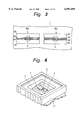
- FIG. 3 is a plan view showing a pattern of photodiodes for detecting optical signals in the laser coupler shown in FIGS. 1 and 2.
- FIG. 4 is a perspective view showing a laser coupler packaged in a flat package.
- FIG. 5 is a schematic diagram for explaining behaviors when a laser coupler is applied to an optical pickup device.
- FIG. 6 is a schematic diagram showing a laser coupler according to the first embodiment of the invention.
- FIG. 7 is a perspective view showing a laser coupler according to a second embodiment of the invention.
- FIG. 8 is a perspective view showing a laser coupler according to a third embodiment of the invention.
- FIG. 9 is a perspective view showing a laser coupler according to a fourth embodiment of the invention.
- FIG. 10 is a perspective view showing a laser coupler according to a fifth embodiment of the invention.
- FIG. 11 is a perspective view showing a laser coupler according to a sixth embodiment of the invention.
- FIG. 12 is a perspective view showing a laser coupler according to another embodiment of the invention.
- FIG. 13 schematically illustrates an optical disc system employing principles of the invention.
- a laser coupler is a kind of a composite optical device.
- FIGS. 1 and 2 show a laser coupler, which is a type of a composite optical device.
- FIG. 1 is a perspective view of the laser coupler
- FIG. 2 is a cross-sectional view of the laser coupler taken along its lengthwise direction.
- the laser coupler includes a microprism 2 made from optical glass and a LOP (Laser On Photodiode) chip having a semiconductor laser 4 supported on a photodiode 3 which are mounted in close locations on a photodiode IC 1.
- the photodiode IC 1 incorporates a pair of photodiodes PD1, PD2 and other well known elements (not shown) such as a current-to-voltage converting amplifier, an operational processing circuit, and so on.
- the photodiode 3 is used to monitor optical outputs from the rear end surface of the semiconductor laser 4 and to control optical output power from the front end surface of the semiconductor laser 4.
- the photodiode 3 also functions to support the semiconductor laser 4 sufficiently high above the surface of the photodiode IC 1 to prevent that the laser beam emitted from the front end surface of the semiconductor laser 4 is reflected by the surface of the photodiode IC 1 and becomes noise light.
- the microprism 2 has a sloped surface 2a, a top surface 2b, a bottom surface 2c, and surfaces 2d and 2e.
- the sloped surface 2a has a half mirror 5
- the top surface 2b has a total reflective film 6
- the bottom surface 2c has an antireflection coating 7
- the end surface 2d is a polished surface
- the end surface 2e has a light absorption film 8.
- a typical dimension of the microprism 2 is 0.6 mm in height, 1.52 mm in total length, 1.8 mm in width and 1.1 mm in length of the top surface 2b.
- a silicon dioxide (SiO 2 ) film (not shown).
- SiO 2 silicon dioxide
- a silicon nitride (SiN) film (not shown).
- SiN silicon nitride
- Another SiO 2 film 9 overlies the SiN film and the photodiode PD2.
- the microprism 2 is mounted on the photodiode IC 1 by bonding the SiO 2 film on the bottom surface 2c of the microprism 2 to the SiO 2 film 9 on the photodiode IC 1 with an adhesive 10.
- the SiN film on the photodiode PD1 and the overlying portion of the SiO 2 film 9 form a half mirror.
- the SiO 2 film on the antireflection coating 7 reinforces the adhesive force of the microprism 2 by the adhesive 10.
- the SiO 2 film 9 passivates the surface of the photodiode IC 1 and reinforces the adhesive force of the microprism 2 by the adhesive 10.
- the photodiodes PD1 and PD2 for detection of optical signals may be of a quarter divisional type. That is, as shown in FIG. 3, the photodiode PD1 has four photodiodes A1 to A4 separated from each other, and the photodiode PD2 has four photodiodes B1 to B4 separated from each other.
- the laser coupler having the above construction is contained in a flat package 11, which may be made from ceramics, and is sealed by a window cap (not shown).
- the laser light L emitted from the front end surface of the semiconductor laser 4 is reflected back by the half mirror (now shown) on the slope surface 2a of the microprism 2, then converged by the objective lens OL, and enters onto the optical disc D.
- the objective lens OL may be integral with or a separate body from the laser coupler.
- the laser light L reflected by the optical disc D enters into the interior of the microprism 2 through the half mirror on the slope surface 2a of the microprism 2.
- One half (50%) of the light entering into the microprism 2 enters into the photodiode PD1, and the other half (50%) is reflected by the half mirror on the photodiode PD1 and the top surface 2b of the microprism 2 successively, and then enters into the photodiode PD2.
- the laser coupler is designed so that the spot size of the laser light L on the photodiode PD1 and that on the photodiode PD2 coincide when the laser light L is focalized onto the record plane of the optical disc D, these spot sizes on the photodiodes PD1 and PD2 gradually differ as the focalized position deviates from the record plane due to a movement of the optical disc D. Therefore, if any difference between an output signal from the photodiode PD1 and an output signal form the photodiode PD2 is regarded as a deviation in focalized position, a focus error signal can be detected.
- the focus error signal is made from (A1+A2+B3+B4) (A3+A4+B1+B2).
- FIG. 6 shows the optical pickup device according to the first embodiment of the invention.
- the optical pickup device is made up of two laser couplers LC1 and LC2, half mirror HM and objective lens OL.
- the laser couplers LC1 and LC2 may have the construction shown in FIGS. 1 and 2, for example.
- the laser coupler LC1 is disposed to share a common optical axis with the half mirror HM and the objective lens OL.
- the laser coupler LC2 is disposed to substantially coincide its incident or exit optical axis with the incident or exit optical axis of the laser coupler LC1 on the half mirror HM.
- the half mirror HM preferably has a polarizing function to polarize laser beams from the laser couplers LC1 and LC2 into different polarized beams to attain the maximum use of light.
- the laser coupler LC1 is designed in accordance with an optimum specification for record and reproduce of a particular kind of optical discs having a particular format. That is, the light emitting wavelength and/or optical output power of its semiconductor laser 4, photodetective properties of the photodiodes PD1 and PD2, and so forth, are optimized for the particular optical disc.
- the laser coupler LC2 is designed in accordance with an optimum specification for record and reproduce of another kind of optical discs having a format different from the former one. That is, the light emitting wavelength and/or optical output power of the semiconductor laser 4, photodetective characteristics of the photodiodes PD1 and PD2, etc. are optimized for the other kind of optical disc.
- a semiconductor laser for light emitting wavelength in the band of 780 nm and optical output power of several milliwatt e.g., a semiconductor laser for light emitting wavelength in the band of 780 nm and optical output power of several milliwatt, a semiconductor laser for light emitting wavelength in the band of 780 nm and optical output power of decades of milliwatt, a semiconductor laser for emitting red light (light emitting wavelength in the band of 635 to 680 nm, approximately) and optical output power of several milliwatt, a semiconductor laser for emitting red light (light emitting wavelength around 635 to 680 nm) and optical output power of decades of milliwatt, a semiconductor laser for emitting blue light (light emitting wavelength around 500 nm) and optical output power of several milliwatt, and a semiconductor laser for emitting blue light (light emitting wavelength around 500 nm) and optical output power of several milliwatt.
- a laser is selected depending on the purpose.
- the optical pickup device Since the optical pickup device according to the first embodiment has the laser couplers LC1 and LC2 having optimum specifications for recording onto and reproducing from two kinds of optical discs in different formats, the optical pickup device is available for recording onto and reproducing from two kinds of optical discs in different formats by selectively using one of these laser couplers LC1 and LC2 depending on the format of an optical disc to be recorded or reproduced. Since these laser couplers LC1 and LC2 can be miniaturized, the optical pickup device can be small-scaled. Moreover, since the semiconductor lasers 4, photodiodes PD1, PD2, and microprisms 2 are previously adjusted in optical axis, etc., the optical pickup device can be assembled easily.
- FIG. 7 shows a laser coupler taken as a second embodiment of the invention, which is used in an optical pickup device.
- the laser coupler according to the second embodiment includes two laser couplers LC1 and LC2 having the same construction shown in FIGS. 1 and 2 and supported in close locations on a common photodiode IC 1 to orient their optical axes in parallel with each other.
- the laser couplers LC1 and LC2 are individually designed in optimum specifications each for record and reproduce of one kind of optical discs in a particular format.
- the distance between the LOP chip of the laser coupler LC1 and the LOP chip of the laser coupler LC2 is typically around 500 um, and 30 to 400 um in minimum, although depending on the mounting accuracy of these LOP chips.
- the objective lens may be an integral body with or a separate body from the laser coupler.
- the laser couplers LC1 and LC2 can commonly use a single objective lens.
- the second embodiment has the same advantages as those of the first embodiment. That is, when the laser coupler according to the second embodiment is used in an optical pickup device, the optical pickup device is available for recording on and reproducing from two kinds of optical discs in different formats by selectively using one of these laser couplers LC1 and LC2 depending on the format of an optical disc to be recorded or reproduced.
- the optical pickup device can be miniaturized and can be fabricated economically because a single photodiode IC 1 and a single package are sufficient to make up the optical pickup device.
- adjustment of optical aces upon incorporating the laser couplers LC1 and LC2 on the photodiode IC 1 is relatively easy, like the laser coupler shown in FIGS. 1 and 2.
- the optical pickup device can be assembled easily.
- FIG. 8 shows a laser coupler taken as a third embodiment of the invention, which is used in an optical pickup device.
- a single common microprism is used for both laser couplers LC1 and LC2.
- a single sloped surface 2a is used by both laser couplers LC1 and LC2.
- the third embodiment is the same as the laser coupler of the second embodiment, and its explanation is omitted here.
- the objective lens may be an integral body with or a separate body from the laser coupler, and the laser couplers LC1 and LC2 can commonly use a single objective lens.
- the third embodiment has the same advantages as those of the second embodiment.
- FIG. 9 shows a laser coupler taken as a fourth embodiment of the invention, which is used in an optical pickup device.
- two laser couplers LC1 and LC2 are incorporated in a face-to-face relationship on a common photodiode IC 1 to share common signal detecting photodiodes PD1 and PD2, common microprism 2, and a common optical axis.
- the microprism 2 has two oppositely positioned sloped surfaces 2a for receiving incident light, which are slanting down toward respective LOP chips of the microprisms 2, respectively.
- the laser coupler according to the fourth embodiment is the same as the laser coupler according to the second embodiment, and its explanation is omitted here.
- a typical distance between a laser beam L emitted from one of the semiconductor laser 4 and reflected by one of the slope surfaces 2a of the microprism 2 and another laser beam L emitted from the other semiconductor laser 4 and reflected by the other slope surface 2a is about 1 mm.
- the objective lens may be integral with or separate from the laser coupler, and both laser couplers LC1 and LC2 may share a common objective lens.
- the fourth embodiment has the same advantages as those of the second embodiment.
- the laser couplers LC1 and LC2 share the common photodiodes PD1 and PD2 and the common microprism 2, the photodiode IC 1 can be miniaturized more, and also the optical pickup device can be small-scaled more.
- FIG. 10 shows a laser coupler taken as a fifth embodiment of the invention, which is used in an optical pickup device.
- a photodiode chip 3 has a two-step top surface 3a.
- a semiconductor laser 4 designed for optimum light emitting wavelength and/or optical output power for writing to and reading from the same kind of discs in a particular format.
- a semiconductor laser 4 designed for optimum light emitting wavelength and/or optical output power for write and read of different kinds of optical discs in different formats.
- the height of the step portion 3a is large enough to prevent interference between laser beams L emitted from the front end surface of both semiconductor lasers 4.
- the fifth embodiment is the same as the laser coupler according to the second embodiment, and its explanation is omitted here.
- the objective lens may be integral with or separate from the laser coupler, and both laser couplers LC1 and LC2 may share a common objective lens.
- the fifth embodiment has the same advantages as those of the second embodiment.
- the laser couplers LC1 and LC2 share the common photodiodes PD1 and PD2, the common microprism 2 and the common microprism sloped surface 2a, the photodiode IC 1 can be miniaturized more, and also the optical pickup device can be small-scaled more.
- FIG. 11 shows a laser coupler taken as a sixth embodiment of the invention, which is used in an optical pickup device.
- two laser couplers LC1 and LC2 are incorporated in a face-to-face relationship on a common photodiode IC 1 to share the common photodiodes PD1, PD2 or PD1' for detecting optical signals (in this case, the photodiode PD2), the common microprism 2, and a common optical axis.
- the laser coupler LC1 uses the photodiodes PD1 and PD2 to detect optical signals
- the laser coupler LC2 uses the photodiodes PD1' and PD2 to detect optical signals.
- the sixth embodiment is the same as the laser coupler according to the second embodiment, and its explanation is omitted here.
- the objective lens may be integral with or separate from the laser coupler, and both laser couplers LC1 and LC2 may share a common objective lens.
- the sixth embodiment has the same advantages as those of the second embodiment.
- the half mirror may be replaced by a polarizing beam splitter, for example, and the objective lens OL may be made as a separate body from the optical pickup device.
- the fourth embodiment has been explained as the laser couplers LC1 and LC2 sharing common photodiodes PD1, PD2 and a common microprism 2
- the sixth embodiment has been explained as the laser coupler LC1 or LC2 sharing a common photodiode PD2 and a common microprism 2
- a pair of photodiodes PD1 and PD2 may be provided for laser couplers LC1 and LC2 to share a common optical axis, so that the laser coupler LC1 and LC2 share only the microprism 2.
- two laser couplers LC1 and LC2 are incorporated on a common photodiode IC 1 to make up a single laser coupler
- three or more laser couplers may be incorporated on a common photodiode IC 1 to form a single laser coupler.
- both laser couplers LC1 and LC2 on common substrate 12 are mounted in a parallel alignment in the lateral direction in a common flat package 11, as shown in FIG. 12, and the package 11 is used in an optical pickup device, the same advantages as those of the above embodiments can be obtained.
- both laser couplers LC1 and LC2 can use a common objective lens.
- the laser couplers LC1 and LC2 are preferably mounted in close locations up to 100 um, for example.
- these laser couplers LC1 and LC2 may be arranged in a serial alignment within the common flat package 11.
- three or more laser couplers may be mounted in a common flat package 11.
- FIG. 13 there is schematically illustrated an optical disc system 100 employing anyone of the previously discussed optical devices of the invention.
- an optical device 102 can be employed in which laser coupler LC1, LC2 to LCn are used to read from and write to an optical recording medium 104 (appropriately supported and driven by well known means not illustrated here).
- circuitry 106 for driving the laser couplers LC1 to LCn in accordance with well known technology. Additionally, there is provided a selector 108 to switch between the laser couplers LC1 to LCn as necessary.
- the selector 108 can take many forms, including a circuit driven by an electronic signal from the driver circuitry 106.
- a switch 110 may be coupled to the circuitry 106 to enable manual selection of a laser coupler, and, therefore, a format, by a user. Otherwise, the selection may be accomplished automatically by reading information stored on the optical recording medium 104 with one or more of the laser couplers. It is believed that such techniques could be readily implemented by those of ordinary skill in the art.
- the selector 108 and driver circuitry 106 may be provided as part of overall circuitry 112 used to operate the optical disc system 100. Such circuitry 112, apart from the inclusion of a selector 108 and the switch means 110 should be well known in the art.
- the optical pickup devices according to the invention are available for writing to and reading from different kinds of optical discs in different formats from each other, and promises miniaturization and easy assembly thereof because the include a plurality of composite optical devices having different read/write specifications.
- an optical pickup device using the composite optical devices is available from writing to and reading from different kinds of optical discs of different read/write formats, and can be miniaturized and assembled easily.
Landscapes
- Physics & Mathematics (AREA)
- Optics & Photonics (AREA)
- Optical Head (AREA)
- Semiconductor Lasers (AREA)
Priority Applications (3)
| Application Number | Priority Date | Filing Date | Title |
|---|---|---|---|
| US09/473,007 US6134208A (en) | 1996-05-27 | 1999-12-28 | Optical pickup device with a plurality of laser couplers |
| US09/675,074 US7038994B1 (en) | 1996-05-27 | 2000-09-28 | Optical pickup device with a plurality of laser couplers |
| US11/084,897 US7113471B2 (en) | 1996-05-27 | 2005-03-21 | Optical pickup device with a plurality of laser couplers |
Applications Claiming Priority (2)
| Application Number | Priority Date | Filing Date | Title |
|---|---|---|---|
| JP8154839A JPH09320098A (ja) | 1996-05-27 | 1996-05-27 | 光ピックアップ装置および複合光学装置 |
| JPP08-154839 | 1996-05-27 |
Related Child Applications (1)
| Application Number | Title | Priority Date | Filing Date |
|---|---|---|---|
| US09/473,007 Continuation US6134208A (en) | 1996-05-27 | 1999-12-28 | Optical pickup device with a plurality of laser couplers |
Publications (1)
| Publication Number | Publication Date |
|---|---|
| US6091689A true US6091689A (en) | 2000-07-18 |
Family
ID=15593021
Family Applications (2)
| Application Number | Title | Priority Date | Filing Date |
|---|---|---|---|
| US08/863,434 Expired - Lifetime US6091689A (en) | 1996-05-27 | 1997-05-27 | Optical pickup device with a plurality of laser couplers |
| US09/473,007 Expired - Lifetime US6134208A (en) | 1996-05-27 | 1999-12-28 | Optical pickup device with a plurality of laser couplers |
Family Applications After (1)
| Application Number | Title | Priority Date | Filing Date |
|---|---|---|---|
| US09/473,007 Expired - Lifetime US6134208A (en) | 1996-05-27 | 1999-12-28 | Optical pickup device with a plurality of laser couplers |
Country Status (10)
| Country | Link |
|---|---|
| US (2) | US6091689A (ko) |
| EP (2) | EP1293973B1 (ko) |
| JP (1) | JPH09320098A (ko) |
| KR (1) | KR100482228B1 (ko) |
| CN (1) | CN1103994C (ko) |
| DE (2) | DE69723919T2 (ko) |
| ID (1) | ID19379A (ko) |
| MY (1) | MY117856A (ko) |
| SG (1) | SG48531A1 (ko) |
| TW (1) | TW377437B (ko) |
Cited By (8)
| Publication number | Priority date | Publication date | Assignee | Title |
|---|---|---|---|---|
| US20010026525A1 (en) * | 2000-01-24 | 2001-10-04 | Shinichi Takahashi | Optical pickup apparatus |
| US6687272B2 (en) * | 2001-09-18 | 2004-02-03 | Kabushiki Kaisha Toshiba | Semiconductor laser device |
| US6740870B1 (en) * | 1998-11-18 | 2004-05-25 | Micron Technology, Inc. | Clear plastic packaging in a CMOS active pixel image sensor |
| US6741539B2 (en) * | 1999-11-30 | 2004-05-25 | Pentax Corporation | Optical system for optical head |
| US6810057B1 (en) * | 1999-11-25 | 2004-10-26 | Matsushita Electric Industrial Co., Ltd. | Semiconductor device and optical pickup device |
| US20060124837A1 (en) * | 2003-01-28 | 2006-06-15 | De Samber Marc A | Optoelectronic input device, method for production of such a device, and method for measuring the movement of an object with the help of such a device |
| US20070035834A1 (en) * | 2003-10-21 | 2007-02-15 | Koninklijke Philips Electronics N.V. | Optical disc drive |
| US7400664B1 (en) * | 2002-03-28 | 2008-07-15 | Fujitsu Limited | Laser array device and laser array control method |
Families Citing this family (12)
| Publication number | Priority date | Publication date | Assignee | Title |
|---|---|---|---|---|
| EP1033793B1 (en) * | 1998-07-14 | 2004-09-29 | Sharp Kabushiki Kaisha | Semiconductor laser device |
| JP2000353332A (ja) | 1999-04-19 | 2000-12-19 | Samsung Electronics Co Ltd | 光出力モジュール及びこれを採用した互換型光ピックアップ装置 |
| US7227817B1 (en) * | 1999-12-07 | 2007-06-05 | Dphi Acquisitions, Inc. | Low profile optical head |
| KR100461704B1 (ko) * | 1999-08-04 | 2004-12-16 | 가부시키가이샤 히타치세이사쿠쇼 | 광헤드 |
| CN1231898C (zh) * | 1999-08-04 | 2005-12-14 | 株式会社日立制作所 | 激光模块和激光头 |
| JP3614746B2 (ja) | 2000-03-01 | 2005-01-26 | 松下電器産業株式会社 | 半導体レーザ装置および光ピックアップ装置 |
| JP2001351266A (ja) * | 2000-04-06 | 2001-12-21 | Fujitsu Ltd | 光ピックアップ及び光記憶装置 |
| JP4121285B2 (ja) * | 2002-02-18 | 2008-07-23 | 株式会社リコー | 光源モジュール、光源装置、光走査装置および画像形成装置 |
| JP2005108321A (ja) * | 2003-09-30 | 2005-04-21 | Konica Minolta Opto Inc | 光ピックアップ装置及び光情報記録再生装置 |
| IL159838A0 (en) | 2004-01-13 | 2004-06-20 | Yehuda Binder | Information device |
| EP2321680B1 (en) * | 2008-06-23 | 2017-09-13 | Imec | Method and system for coupling radiation |
| DE102013220787A1 (de) * | 2013-10-15 | 2015-04-16 | Robert Bosch Gmbh | Mikromechanisches Bauelement mit integrierter Photodiode und Mikroprojektor |
Citations (30)
| Publication number | Priority date | Publication date | Assignee | Title |
|---|---|---|---|---|
| EP0278406A2 (en) * | 1987-02-06 | 1988-08-17 | Sony Corporation | Optical pickup head |
| JPS6484687A (en) * | 1987-09-28 | 1989-03-29 | Nippon Telegraph & Telephone | Surface emission semiconductor laser with monitor |
| JPH05145197A (ja) * | 1991-11-22 | 1993-06-11 | Furukawa Electric Co Ltd:The | レーザダイオードアレイ素子 |
| EP0550036A2 (en) * | 1991-12-27 | 1993-07-07 | Sony Corporation | Optical apparatus |
| US5247167A (en) * | 1992-08-06 | 1993-09-21 | International Business Machines Corporation | Multiple beam power monitoring system and method with radiation detection and focusing means of overlapping beams |
| JPH05266529A (ja) * | 1992-03-17 | 1993-10-15 | Sony Corp | 光学ヘッドおよびその製造方法 |
| EP0630002A1 (en) * | 1993-06-14 | 1994-12-21 | Nogatech Ltd. | Method and apparatus for the simultaneous writing of data on an optical disk |
| US5446719A (en) * | 1992-02-05 | 1995-08-29 | Sharp Kabushiki Kaisha | Optical information reproducing apparatus |
| US5465243A (en) * | 1992-04-24 | 1995-11-07 | E-Systems, Inc. | Optical recorder and reader of data on light sensitive media |
| US5483511A (en) * | 1993-02-17 | 1996-01-09 | Vixel Corporation | Multiple beam optical memory system with solid-state lasers |
| US5544143A (en) * | 1994-06-14 | 1996-08-06 | Eastman Kodak Company | Read/write laser-detector-grating unit (LDGU) with an orthogonally-arranged focus and tracking sensor system |
| US5566142A (en) * | 1994-02-10 | 1996-10-15 | Olympus Optical Co., Ltd. | Apparatus using an optical pickup |
| US5598394A (en) * | 1994-05-19 | 1997-01-28 | Sanyo Electric Co., Ltd. | Optical pick-up |
| US5615203A (en) * | 1993-12-20 | 1997-03-25 | Matsushita Electric Industrial Co., Ltd. | Floating-type optical head having incorporated therein a floating slider and an optical device which floats with the slider, includes a light source, condensing unit and photodetector and is supported movably relative to the floating slider |
| US5627806A (en) * | 1992-05-14 | 1997-05-06 | Olympus Optical Co., Ltd. | Optical head having beam splitting surface curved to present a substantially uniform angle |
| US5629917A (en) * | 1994-12-05 | 1997-05-13 | Kamatani; Yasuo | Integrated optical pick-up emits light beams of selective wavelengths to an optical disk with multiple data layers |
| US5663940A (en) * | 1993-11-19 | 1997-09-02 | Sony Corporation | Optical pickup apparatus including hologram element |
| US5680385A (en) * | 1995-03-30 | 1997-10-21 | Nec Corporation | Optical head with a heat sink |
| US5680384A (en) * | 1992-11-17 | 1997-10-21 | Seiko Epson Corporation | Laser emission unit, optical head and optical memory device |
| US5696749A (en) * | 1996-06-28 | 1997-12-09 | Eastman Kodak Company | Dual-wavelength optical recording head utilizing grating beam splitter and integrated laser and detectors |
| US5708644A (en) * | 1996-02-28 | 1998-01-13 | Fujitsu Limited | Optical head for optical disk drive |
| US5727111A (en) * | 1995-06-19 | 1998-03-10 | Sony Corporation | Optical pick-up and light detecting cover therefor |
| US5729519A (en) * | 1993-03-26 | 1998-03-17 | Matsushita Electronics Corporation | Optical head including a semiconductor laser having a non-scatter area to diffuse incident light beams |
| US5761178A (en) * | 1994-10-18 | 1998-06-02 | Matsushita Electric Industrial Co., Ltd. | Optical integrating element and integration type optical pickup device using the same |
| US5781676A (en) * | 1995-10-30 | 1998-07-14 | Sharp Kabushiki Kaisha | Waveguide integrated optical pickup device and optical waveguide element |
| US5787058A (en) * | 1995-05-31 | 1998-07-28 | Daewoo Electronics Co., Ltd. | Optical pickup apparatus utilizing a polygonal prism |
| US5790504A (en) * | 1995-06-02 | 1998-08-04 | Matsushita Electric Industrial Co., Ltd. | Integrated optical head with an emitting light splitting polarizing prism and a detecting light splitting polarizing element |
| US5852595A (en) * | 1996-04-26 | 1998-12-22 | Nec Corporation | Device for initializing an optical disc |
| US5933402A (en) * | 1996-05-15 | 1999-08-03 | Samsung Electronics Co., Ltd. | Optical pickup capable of compatibly adopting disks of different thickness |
| US5936929A (en) * | 1997-05-02 | 1999-08-10 | Motorola, Inc. | Optical submodule and method for making |
Family Cites Families (8)
| Publication number | Priority date | Publication date | Assignee | Title |
|---|---|---|---|---|
| US4694447A (en) * | 1984-07-12 | 1987-09-15 | International Business Machines Corp. | Optical signal recorders employing two lasers and methods therefor |
| JP2590902B2 (ja) * | 1987-07-30 | 1997-03-19 | ソニー株式会社 | 発光・受光複合素子 |
| JPH01154326A (ja) * | 1987-12-10 | 1989-06-16 | Fujitsu Ltd | 光ディスク用ヘッド |
| US4877311A (en) * | 1988-01-19 | 1989-10-31 | Kearfott Guidance & Navigation Corporation | Laser power monitoring optics for a ring laser gyroscope |
| JPH0677336B2 (ja) * | 1988-12-09 | 1994-09-28 | シャープ株式会社 | 光ピックアップ装置 |
| JPH02192044A (ja) * | 1989-01-19 | 1990-07-27 | Toshiba Corp | マルチビーム分離装置 |
| US5235581A (en) * | 1990-08-09 | 1993-08-10 | Matsushita Electric Industrial Co., Ltd. | Optical recording/reproducing apparatus for optical disks with various disk substrate thicknesses |
| US5796688A (en) * | 1996-09-16 | 1998-08-18 | Eastman Kodak Company | Optical drive apparatus for use with a multilayer optical data storage device |
-
1996
- 1996-05-27 JP JP8154839A patent/JPH09320098A/ja active Pending
-
1997
- 1997-05-22 DE DE69723919T patent/DE69723919T2/de not_active Expired - Lifetime
- 1997-05-22 EP EP02025650A patent/EP1293973B1/en not_active Expired - Lifetime
- 1997-05-22 EP EP97108319A patent/EP0810589B1/en not_active Expired - Lifetime
- 1997-05-22 DE DE69739890T patent/DE69739890D1/de not_active Expired - Lifetime
- 1997-05-22 TW TW086106919A patent/TW377437B/zh not_active IP Right Cessation
- 1997-05-24 MY MYPI97002274A patent/MY117856A/en unknown
- 1997-05-26 SG SG1997001704A patent/SG48531A1/en unknown
- 1997-05-26 ID IDP971751A patent/ID19379A/id unknown
- 1997-05-27 KR KR1019970021055A patent/KR100482228B1/ko not_active IP Right Cessation
- 1997-05-27 CN CN97113193A patent/CN1103994C/zh not_active Expired - Lifetime
- 1997-05-27 US US08/863,434 patent/US6091689A/en not_active Expired - Lifetime
-
1999
- 1999-12-28 US US09/473,007 patent/US6134208A/en not_active Expired - Lifetime
Patent Citations (30)
| Publication number | Priority date | Publication date | Assignee | Title |
|---|---|---|---|---|
| EP0278406A2 (en) * | 1987-02-06 | 1988-08-17 | Sony Corporation | Optical pickup head |
| JPS6484687A (en) * | 1987-09-28 | 1989-03-29 | Nippon Telegraph & Telephone | Surface emission semiconductor laser with monitor |
| JPH05145197A (ja) * | 1991-11-22 | 1993-06-11 | Furukawa Electric Co Ltd:The | レーザダイオードアレイ素子 |
| EP0550036A2 (en) * | 1991-12-27 | 1993-07-07 | Sony Corporation | Optical apparatus |
| US5446719A (en) * | 1992-02-05 | 1995-08-29 | Sharp Kabushiki Kaisha | Optical information reproducing apparatus |
| JPH05266529A (ja) * | 1992-03-17 | 1993-10-15 | Sony Corp | 光学ヘッドおよびその製造方法 |
| US5465243A (en) * | 1992-04-24 | 1995-11-07 | E-Systems, Inc. | Optical recorder and reader of data on light sensitive media |
| US5627806A (en) * | 1992-05-14 | 1997-05-06 | Olympus Optical Co., Ltd. | Optical head having beam splitting surface curved to present a substantially uniform angle |
| US5247167A (en) * | 1992-08-06 | 1993-09-21 | International Business Machines Corporation | Multiple beam power monitoring system and method with radiation detection and focusing means of overlapping beams |
| US5680384A (en) * | 1992-11-17 | 1997-10-21 | Seiko Epson Corporation | Laser emission unit, optical head and optical memory device |
| US5483511A (en) * | 1993-02-17 | 1996-01-09 | Vixel Corporation | Multiple beam optical memory system with solid-state lasers |
| US5729519A (en) * | 1993-03-26 | 1998-03-17 | Matsushita Electronics Corporation | Optical head including a semiconductor laser having a non-scatter area to diffuse incident light beams |
| EP0630002A1 (en) * | 1993-06-14 | 1994-12-21 | Nogatech Ltd. | Method and apparatus for the simultaneous writing of data on an optical disk |
| US5663940A (en) * | 1993-11-19 | 1997-09-02 | Sony Corporation | Optical pickup apparatus including hologram element |
| US5615203A (en) * | 1993-12-20 | 1997-03-25 | Matsushita Electric Industrial Co., Ltd. | Floating-type optical head having incorporated therein a floating slider and an optical device which floats with the slider, includes a light source, condensing unit and photodetector and is supported movably relative to the floating slider |
| US5566142A (en) * | 1994-02-10 | 1996-10-15 | Olympus Optical Co., Ltd. | Apparatus using an optical pickup |
| US5598394A (en) * | 1994-05-19 | 1997-01-28 | Sanyo Electric Co., Ltd. | Optical pick-up |
| US5544143A (en) * | 1994-06-14 | 1996-08-06 | Eastman Kodak Company | Read/write laser-detector-grating unit (LDGU) with an orthogonally-arranged focus and tracking sensor system |
| US5761178A (en) * | 1994-10-18 | 1998-06-02 | Matsushita Electric Industrial Co., Ltd. | Optical integrating element and integration type optical pickup device using the same |
| US5629917A (en) * | 1994-12-05 | 1997-05-13 | Kamatani; Yasuo | Integrated optical pick-up emits light beams of selective wavelengths to an optical disk with multiple data layers |
| US5680385A (en) * | 1995-03-30 | 1997-10-21 | Nec Corporation | Optical head with a heat sink |
| US5787058A (en) * | 1995-05-31 | 1998-07-28 | Daewoo Electronics Co., Ltd. | Optical pickup apparatus utilizing a polygonal prism |
| US5790504A (en) * | 1995-06-02 | 1998-08-04 | Matsushita Electric Industrial Co., Ltd. | Integrated optical head with an emitting light splitting polarizing prism and a detecting light splitting polarizing element |
| US5727111A (en) * | 1995-06-19 | 1998-03-10 | Sony Corporation | Optical pick-up and light detecting cover therefor |
| US5781676A (en) * | 1995-10-30 | 1998-07-14 | Sharp Kabushiki Kaisha | Waveguide integrated optical pickup device and optical waveguide element |
| US5708644A (en) * | 1996-02-28 | 1998-01-13 | Fujitsu Limited | Optical head for optical disk drive |
| US5852595A (en) * | 1996-04-26 | 1998-12-22 | Nec Corporation | Device for initializing an optical disc |
| US5933402A (en) * | 1996-05-15 | 1999-08-03 | Samsung Electronics Co., Ltd. | Optical pickup capable of compatibly adopting disks of different thickness |
| US5696749A (en) * | 1996-06-28 | 1997-12-09 | Eastman Kodak Company | Dual-wavelength optical recording head utilizing grating beam splitter and integrated laser and detectors |
| US5936929A (en) * | 1997-05-02 | 1999-08-10 | Motorola, Inc. | Optical submodule and method for making |
Non-Patent Citations (4)
| Title |
|---|
| Patent Abstracts of Japan, vol. 013 (E 788), Jul. 17, 1989 & JP 01084687A (Nippon Telegraph & Telephone Corp.) Mar. 29, 1989. * |
| Patent Abstracts of Japan, vol. 013 (E-788), Jul. 17, 1989 & JP-01084687A (Nippon Telegraph & Telephone Corp.) Mar. 29, 1989. |
| Patent Abstracts of Japan, vol. 017, No. 528 (E 1437), Sep. 22, 1993 & JP05 145197A (Furukawa Electric Co., Ltd.) Jun. 11, 1993. * |
| Patent Abstracts of Japan, vol. 017, No. 528 (E-1437), Sep. 22, 1993 & JP05-145197A (Furukawa Electric Co., Ltd.) Jun. 11, 1993. |
Cited By (11)
| Publication number | Priority date | Publication date | Assignee | Title |
|---|---|---|---|---|
| US6740870B1 (en) * | 1998-11-18 | 2004-05-25 | Micron Technology, Inc. | Clear plastic packaging in a CMOS active pixel image sensor |
| US6810057B1 (en) * | 1999-11-25 | 2004-10-26 | Matsushita Electric Industrial Co., Ltd. | Semiconductor device and optical pickup device |
| US6741539B2 (en) * | 1999-11-30 | 2004-05-25 | Pentax Corporation | Optical system for optical head |
| US20010026525A1 (en) * | 2000-01-24 | 2001-10-04 | Shinichi Takahashi | Optical pickup apparatus |
| US7079474B2 (en) * | 2000-01-24 | 2006-07-18 | Pioneer Corporation | Optical pickup apparatus |
| US6687272B2 (en) * | 2001-09-18 | 2004-02-03 | Kabushiki Kaisha Toshiba | Semiconductor laser device |
| US7400664B1 (en) * | 2002-03-28 | 2008-07-15 | Fujitsu Limited | Laser array device and laser array control method |
| US20080181271A1 (en) * | 2002-03-28 | 2008-07-31 | Fujitsu Limited | Laser array device and laser array control method |
| US20060124837A1 (en) * | 2003-01-28 | 2006-06-15 | De Samber Marc A | Optoelectronic input device, method for production of such a device, and method for measuring the movement of an object with the help of such a device |
| US7368703B2 (en) * | 2003-01-28 | 2008-05-06 | Koninklijke Philips Electronics, N.V. | Optoelectronic input device, method for production of such a device, and method for measuring the movement of an object with the help of such a device |
| US20070035834A1 (en) * | 2003-10-21 | 2007-02-15 | Koninklijke Philips Electronics N.V. | Optical disc drive |
Also Published As
| Publication number | Publication date |
|---|---|
| DE69723919T2 (de) | 2004-07-15 |
| EP0810589A3 (en) | 1998-07-01 |
| EP1293973B1 (en) | 2010-05-26 |
| EP0810589A2 (en) | 1997-12-03 |
| TW377437B (en) | 1999-12-21 |
| KR970076587A (ko) | 1997-12-12 |
| JPH09320098A (ja) | 1997-12-12 |
| EP1293973A2 (en) | 2003-03-19 |
| CN1103994C (zh) | 2003-03-26 |
| EP0810589B1 (en) | 2003-08-06 |
| KR100482228B1 (ko) | 2005-07-18 |
| DE69739890D1 (de) | 2010-07-08 |
| EP1293973A3 (en) | 2004-10-13 |
| ID19379A (id) | 1998-07-09 |
| SG48531A1 (en) | 1998-04-17 |
| DE69723919D1 (de) | 2003-09-11 |
| CN1181576A (zh) | 1998-05-13 |
| US6134208A (en) | 2000-10-17 |
| MY117856A (en) | 2004-08-30 |
Similar Documents
| Publication | Publication Date | Title |
|---|---|---|
| US6091689A (en) | Optical pickup device with a plurality of laser couplers | |
| EP0840305B1 (en) | Optical apparatus | |
| US6937554B2 (en) | Optical pickup apparatus having an improved holographic unit, and optical disk drive including the same | |
| EP1130582B1 (en) | Semiconductor laser device and optical pickup device using the same | |
| KR100253810B1 (ko) | 이파장 광원모듈 및 그를 이용한 광픽업장치 | |
| US7113471B2 (en) | Optical pickup device with a plurality of laser couplers | |
| US6504812B2 (en) | Optical pickup device with a plurality of laser couplers | |
| KR100294886B1 (ko) | 호환형 광픽업장치 | |
| US6081497A (en) | Optical pickup having compatibility with a digital versatile disk and a compact disk-recordable | |
| KR100293464B1 (ko) | 이파장광원모듈및그의제조방법과그를이용한광픽업장치 | |
| JP2002109771A (ja) | 光学装置 | |
| JPH10143908A (ja) | 光ピックアップ装置 | |
| JPH11161993A (ja) | 多波長光集積素子及び光学ピックアップ装置 | |
| KR100236017B1 (ko) | 두 개의 광원을 갖는 레이저 다이오드 패키지 | |
| JPH05198030A (ja) | 光磁気記録用レーザカプラ | |
| JPH05205339A (ja) | 光磁気記録用偏光光学系 | |
| KR20000016993A (ko) | 광픽업 장치 | |
| KR19980056217A (ko) | 레이저 다이오드 패키지 및 이를 이용한 이종 광 디스크용 광 픽업장치 | |
| US20030152012A1 (en) | Optical pickup device | |
| JPH11273131A (ja) | 光学装置 | |
| JPH10321899A (ja) | 光集積素子、及び、その光集積素子における信号検出方法、並びに、光学式情報読み取り装置 | |
| KR20020063668A (ko) | 멀티 파장의 발광부가 적층 형성된 레이저 다이오드를포함한 광픽업 장치 | |
| KR19980072248A (ko) | 이종 광 디스크용 광 픽업장치 | |
| JPH10321898A (ja) | 光集積素子及びその製造方法、並びに、光学式情報読み取り装置 | |
| JP2001126302A (ja) | 集積光学素子及び光学ピックアップ装置 |
Legal Events
| Date | Code | Title | Description |
|---|---|---|---|
| AS | Assignment |
Owner name: SONY CORPORATION, JAPAN Free format text: ASSIGNMENT OF ASSIGNORS INTEREST;ASSIGNORS:TANIGUCHI, TADASHI;KOJIMA, CHIAKI;REEL/FRAME:008875/0846;SIGNING DATES FROM 19971114 TO 19971118 |
|
| STCF | Information on status: patent grant |
Free format text: PATENTED CASE |
|
| FPAY | Fee payment |
Year of fee payment: 4 |
|
| FPAY | Fee payment |
Year of fee payment: 8 |
|
| REMI | Maintenance fee reminder mailed | ||
| FEPP | Fee payment procedure |
Free format text: PAYOR NUMBER ASSIGNED (ORIGINAL EVENT CODE: ASPN); ENTITY STATUS OF PATENT OWNER: LARGE ENTITY Free format text: PAYER NUMBER DE-ASSIGNED (ORIGINAL EVENT CODE: RMPN); ENTITY STATUS OF PATENT OWNER: LARGE ENTITY |
|
| FPAY | Fee payment |
Year of fee payment: 12 |