US11628722B2 - Vehicle - Google Patents
Vehicle Download PDFInfo
- Publication number
- US11628722B2 US11628722B2 US16/861,859 US202016861859A US11628722B2 US 11628722 B2 US11628722 B2 US 11628722B2 US 202016861859 A US202016861859 A US 202016861859A US 11628722 B2 US11628722 B2 US 11628722B2
- Authority
- US
- United States
- Prior art keywords
- vehicle
- coupled
- frame
- arms
- final drive
- Prior art date
- Legal status (The legal status is an assumption and is not a legal conclusion. Google has not performed a legal analysis and makes no representation as to the accuracy of the status listed.)
- Active, expires
Links
Images


Classifications
-
- B—PERFORMING OPERATIONS; TRANSPORTING
- B62—LAND VEHICLES FOR TRAVELLING OTHERWISE THAN ON RAILS
- B62D—MOTOR VEHICLES; TRAILERS
- B62D23/00—Combined superstructure and frame, i.e. monocoque constructions
- B62D23/005—Combined superstructure and frame, i.e. monocoque constructions with integrated chassis in the whole shell, e.g. meshwork, tubes, or the like
-
- B—PERFORMING OPERATIONS; TRANSPORTING
- B60—VEHICLES IN GENERAL
- B60K—ARRANGEMENT OR MOUNTING OF PROPULSION UNITS OR OF TRANSMISSIONS IN VEHICLES; ARRANGEMENT OR MOUNTING OF PLURAL DIVERSE PRIME-MOVERS IN VEHICLES; AUXILIARY DRIVES FOR VEHICLES; INSTRUMENTATION OR DASHBOARDS FOR VEHICLES; ARRANGEMENTS IN CONNECTION WITH COOLING, AIR INTAKE, GAS EXHAUST OR FUEL SUPPLY OF PROPULSION UNITS IN VEHICLES
- B60K17/00—Arrangement or mounting of transmissions in vehicles
- B60K17/04—Arrangement or mounting of transmissions in vehicles characterised by arrangement, location or kind of gearing
- B60K17/043—Transmission unit disposed in on near the vehicle wheel, or between the differential gear unit and the wheel
-
- B—PERFORMING OPERATIONS; TRANSPORTING
- B60—VEHICLES IN GENERAL
- B60K—ARRANGEMENT OR MOUNTING OF PROPULSION UNITS OR OF TRANSMISSIONS IN VEHICLES; ARRANGEMENT OR MOUNTING OF PLURAL DIVERSE PRIME-MOVERS IN VEHICLES; AUXILIARY DRIVES FOR VEHICLES; INSTRUMENTATION OR DASHBOARDS FOR VEHICLES; ARRANGEMENTS IN CONNECTION WITH COOLING, AIR INTAKE, GAS EXHAUST OR FUEL SUPPLY OF PROPULSION UNITS IN VEHICLES
- B60K17/00—Arrangement or mounting of transmissions in vehicles
- B60K17/04—Arrangement or mounting of transmissions in vehicles characterised by arrangement, location or kind of gearing
- B60K17/06—Arrangement or mounting of transmissions in vehicles characterised by arrangement, location or kind of gearing of change-speed gearing
- B60K17/08—Arrangement or mounting of transmissions in vehicles characterised by arrangement, location or kind of gearing of change-speed gearing of mechanical type
-
- B—PERFORMING OPERATIONS; TRANSPORTING
- B62—LAND VEHICLES FOR TRAVELLING OTHERWISE THAN ON RAILS
- B62D—MOTOR VEHICLES; TRAILERS
- B62D27/00—Connections between superstructure or understructure sub-units
- B62D27/02—Connections between superstructure or understructure sub-units rigid
- B62D27/023—Assembly of structural joints
-
- B—PERFORMING OPERATIONS; TRANSPORTING
- B62—LAND VEHICLES FOR TRAVELLING OTHERWISE THAN ON RAILS
- B62D—MOTOR VEHICLES; TRAILERS
- B62D33/00—Superstructures for load-carrying vehicles
- B62D33/02—Platforms; Open load compartments
-
- B—PERFORMING OPERATIONS; TRANSPORTING
- B62—LAND VEHICLES FOR TRAVELLING OTHERWISE THAN ON RAILS
- B62D—MOTOR VEHICLES; TRAILERS
- B62D33/00—Superstructures for load-carrying vehicles
- B62D33/02—Platforms; Open load compartments
- B62D33/0207—Connections of movable or detachable racks or stanchions to platforms
-
- B—PERFORMING OPERATIONS; TRANSPORTING
- B60—VEHICLES IN GENERAL
- B60K—ARRANGEMENT OR MOUNTING OF PROPULSION UNITS OR OF TRANSMISSIONS IN VEHICLES; ARRANGEMENT OR MOUNTING OF PLURAL DIVERSE PRIME-MOVERS IN VEHICLES; AUXILIARY DRIVES FOR VEHICLES; INSTRUMENTATION OR DASHBOARDS FOR VEHICLES; ARRANGEMENTS IN CONNECTION WITH COOLING, AIR INTAKE, GAS EXHAUST OR FUEL SUPPLY OF PROPULSION UNITS IN VEHICLES
- B60K17/00—Arrangement or mounting of transmissions in vehicles
- B60K17/04—Arrangement or mounting of transmissions in vehicles characterised by arrangement, location or kind of gearing
- B60K17/16—Arrangement or mounting of transmissions in vehicles characterised by arrangement, location or kind of gearing of differential gearing
- B60K17/165—Arrangement or mounting of transmissions in vehicles characterised by arrangement, location or kind of gearing of differential gearing provided between independent half axles
Definitions
- the present invention relates to side-by-side vehicles and all-terrain vehicles.
- ATVs all-terrain vehicles
- UVs utility vehicles
- ATVs are used to carry one or two passengers and a small amount of cargo over a variety of terrains.
- specialty ATVs such as those used for trail riding, racing, and cargo hauling have entered the market place.
- Most ATVs include seating for up to two passengers which are either seated side-by-side or with the passenger positioned behind the driver of the ATV.
- Side-by-side ATVs in which the driver and passenger are seated beside each other on laterally spaced apart seats, have become popular because of the ability to allow the passenger to share the driver's viewpoint.
- a vehicle in a first embodiment, comprises a frame having a first end, the frame having an opening therethrough; front and rear wheels support the frame; a powertrain comprises a final drive drivingly coupled to at least some of the front and rear wheels, the final drive is positioned adjacent to the opening; whereby the final drive may be removed from the frame through the opening.
- a vehicle comprises a frame comprising a main frame portion and a front removable frame portion; front and rear wheels; a front suspension coupled to the main frame portion with the front wheels being coupled to the front suspension; a rear suspension coupled to the main frame portion with the rear wheels being coupled to the rear suspension; and a powertrain drivingly coupled to the front and rear wheels; whereby the front removable frame portion may be removed from the main frame portion to expose a portion of the powertrain.
- a vehicle in another embodiment, comprises a frame; front and rear wheels; a front suspension coupled to the frame; a powertrain drivingly coupled to the front and rear wheels, comprising a front final drive drivingly coupled to the front wheels; a front prop shaft coupling the powertrain to the front wheels; and a steering mechanism positioned above the prop shaft and rearward of the final drive.
- a vehicle comprises a frame; front and rear wheels; a front suspension coupled to the frame comprising upper and lower A-arms on a left and right hand side of the vehicle, a linear force element coupled between the frame and the lower A-arms on each side of the vehicle; a powertrain drivingly coupled to the front and rear wheels, comprising a front final drive drivingly coupled to the front wheels; a left side half shaft coupled between the left wheel and the front final drive; a right half shaft coupled between the right wheel and the front final drive; and a coupling between the linear force elements and the lower A-arms straddles the half shafts.
- a vehicle in another embodiment, comprises a frame; front and rear wheels supporting the frame; an operator's compartment intermediate the front and rear wheels having at least one seat; a transmission positioned rearward of the seat, the transmission comprising a transmission housing extending generally laterally of a vehicle longitudinal direction and having an engine interface on one lateral side of the transmission housing and a geared transmission portion on the opposite lateral side as the engine interface, and front and rear output shafts for propelling the front and rear wheels; and an engine coupled to the engine interface and powering the geared transmission portion.
- a vehicle in another embodiment, comprises a frame; front and rear wheels supporting the frame; an operator's compartment intermediate the front and rear wheels having at least one seat; a transmission comprising a transmission housing having an engine interface on one lateral side of the transmission housing and a geared transmission portion on the opposite lateral side as the engine interface, and front and rear output shafts for propelling the front and rear wheels; an engine coupled to the engine interface; an intermediate shaft is provided at the engine interface, having an input shaft and an output shaft, wherein the engine is drivingly coupled to the input shaft of the intermediate shaft; and a continuously variable transmission coupling the input shaft of the intermediate shaft, wherein an air volume is defined adjacent to an interface of the intermediate shaft and the continuously variable transmission.
- a vehicle in another embodiment, comprises a frame; front and rear wheels; a front suspension coupled to the frame; a powertrain drivingly coupled to the front and rear wheels, comprising a front final drive drivingly coupled to the front wheels; a front prop shaft coupling the powertrain to the front wheels; and a stabilizer bar positioned generally over a top of the final drive.
- a vehicle comprise a frame; front and rear wheels supporting the frame; an operator's compartment intermediate the front and rear wheels having at least one seat; a cab frame coupled to the frame and generally surrounding the operator's compartment, the cab frame including first and second generally longitudinally extending frame rails, and at least a first horizontally extending frame rail coupled to the longitudinally extending frame rails; a socket located on a portion of the frame having a tapered socket portion; and a tapered fitting portion provided on one of the frame rails coupled to the tapered socket portion.
- a vehicle comprises a frame comprising a main frame portion and a front removable frame portion; front and rear wheels; a front suspension coupled to the main frame portion with the front wheels being coupled to the front suspension; a rear suspension coupled to the main frame portion with the rear wheels being coupled to the rear suspension; and a powertrain drivingly coupled to the front and rear wheels; whereby the front removable frame portion may be removed from the main frame portion to expose a portion of the powertrain.
- FIG. 1 is a front left perspective view of the vehicle of the present invention without the body panels;
- FIG. 2 is a right rear perspective view of the vehicle of FIG. 1 ;
- FIG. 3 is a left side view of the vehicle of FIG. 1 ;
- FIG. 4 is a right side view of the vehicle of FIG. 1 ;
- FIG. 5 is a top view of the vehicle of FIG. 1 ;
- FIG. 6 is a front view of the vehicle of FIG. 1 ;
- FIG. 7 is a rear view of the vehicle of FIG. 1 ;
- FIG. 8 is a front left perspective view of the frame of the vehicle of FIG. 1 ;
- FIG. 9 is a rear right perspective view of the frame shown in FIG. 8 ;
- FIG. 10 is a front left perspective view of the front suspension of the vehicle.
- FIG. 11 is a left side view of the front suspension of the vehicle.
- FIG. 12 is a view similar to that of FIG. 10 , having removed the frame;
- FIG. 13 is a rear perspective view of the suspension as shown in FIG. 12 ;
- FIG. 14 is an enlarged view of the front right side suspension
- FIG. 15 is a partially exploded view of the suspension of FIG. 14 ;
- FIG. 16 shows a floating rotor design for the vehicle
- FIG. 17 is a left front perspective view of the front removable frame portion
- FIG. 18 is a partially exploded view of the front removable frame portion of FIG. 19 ;
- FIG. 19 is a front left perspective view of the final drive removed from the front frame of FIG. 18 ;
- FIG. 20 is a bottom view of the vehicle showing the rear suspension
- FIG. 21 is a right front perspective view of a portion of the rear suspension
- FIG. 22 shows an exploded view of the rear suspension of FIG. 21 ;
- FIG. 23 is a front left perspective view of the powertrain of the vehicle.
- FIG. 24 is a right rear perspective view of the engine
- FIG. 25 is a right rear perspective view of the engine oil pan and lubrication system
- FIG. 26 is a view similar to that of FIG. 25 showing the front scavenge pump exploded away from the oil pan;
- FIG. 27 is a cross-sectional view through lines 27 - 27 of FIG. 25 ;
- FIG. 28 is a cross-sectional view through lines 28 - 28 of FIG. 25 ;
- FIG. 29 is a left-hand side view of the engine mounts
- FIG. 30 is a left rear perspective view of the engine mounts
- FIG. 31 is similar to that of FIG. 30 , showing the engine and engine mounts in an exploded manner away from the frame;
- FIG. 32 is a right-hand side view of the engine mounts
- FIG. 33 is a right rear perspective view of the engine mounts
- FIG. 34 is a left front perspective view of the transmission coupled to the front final drive
- FIG. 35 is a rear perspective view of the transmission shown in FIG. 34 ;
- FIG. 36 is a cross-sectional view through lines 36 - 36 of FIG. 34 ;
- FIG. 37 is an exploded view of the slip clutch portion of the transmission
- FIG. 38 shows a diagrammatical flow chart showing the torque control model
- FIG. 39 is a front perspective view of the continuously variable transmission (CVT) of the powertrain shown in FIG. 23 ;
- FIG. 40 is the inner housing of the CVT shown with the drive and driven clutches removed;
- FIG. 41 is a cross-sectional view through lines 41 - 41 of FIG. 39 ;
- FIG. 42 shows a coolant level switch for the coolant bottle
- FIG. 43 is a front perspective view of the utility bed of the vehicle.
- FIG. 44 shows a right-side view of the passenger seat and fuel tank configuration
- FIG. 45 shows a top view of the seat shown in FIG. 44 ;
- FIG. 46 shows an enlarged view of the rear cab frame support area
- FIG. 47 is a fragmentary enlargement of the right rear portion of the cab frame support area shown in FIG. 46 ;
- FIG. 48 is a cross-sectional view through lines 48 - 48 of FIG. 46 ;
- FIG. 49 is a view showing the fully assembled taper lock fitting
- FIG. 50 shows an enlarged portion of the area denoted in FIG. 46 ;
- FIG. 51 shows a left front perspective view of an alternative front frame portion to that of the front removable frame portion of FIG. 17 ;
- FIG. 52 is a partially exploded view of the front frame portion of FIG. 51 ;
- FIG. 53 is a front left perspective view of the final drive removed from the front frame portion of FIG. 51 ;
- FIG. 54 is a left side view of front frame portion of FIG. 53 ;
- FIG. 55 is a right side view of front frame portion of FIG. 53 ;
- FIG. 56 is a left front perspective view of an alternative frame of the vehicle of FIG. 1 ;
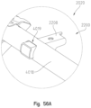
- FIG. 56 A is a left front perspective view of a portion of the frame of FIG. 56 ;
- FIG. 57 is a right rear perspective view of the frame of FIG. 56 ;
- FIG. 58 is a left front perspective view of the frame of FIG. 56 coupled to an alternative cab frame;
- FIG. 59 is a detailed perspective view of a tie-down member of the frame of FIG. 56 ;
- FIG. 60 is a detailed perspective view of a tie-down member of the frame of FIG. 57 ;
- FIG. 61 is a left front perspective view of the cab frame of FIG. 58 ;
- FIG. 62 is a left rear perspective view of an underside of the cab frame of FIG. 61 ;
- FIG. 63 is a left rear perspective view of a support area of a rear portion of the frame of FIG. 57 configured to support a utility bed, a portion of an air intake, a portion of an exhaust, and a portion of a cooling system;
- FIG. 64 is a left rear perspective view of the support area of FIG. 63 ;
- FIG. 65 is an exploded view of the support area of FIG. 64 ;
- FIG. 66 is a left rear perspective view of an underside of the support area of FIG. 63 ;
- FIG. 67 is a right rear perspective view of the underside of the support area of FIG. 66 ;
- FIG. 68 is an exploded view of the support area of FIG. 67 ;
- FIG. 69 is a left front perspective view of a portion of an alternative front suspension of the vehicle of FIG. 1 ;
- FIG. 70 is an exploded view of a lower portion of a linear force element of the front suspension of FIG. 69 and a clevis of the linear force element;
- FIG. 71 is a right rear perspective view of an alternative front braking system of the vehicle of FIG. 1 ;
- FIG. 72 is a left front perspective view of a brake disc and brake caliper of the front braking system of FIG. 71 ;
- FIG. 73 is an exploded view of the brake caliper and brake pads of the front braking system of FIG. 72 ;
- FIG. 74 is a right rear perspective view of an alternative rear braking system of the vehicle of FIG. 1 ;
- FIG. 75 is a left front perspective view of an alternative rear suspension of the vehicle of FIG. 1 ;
- FIG. 76 A is a left front perspective view of a toe link coupling of the rear suspension of FIG. 75 ;
- FIG. 76 B is an exploded view of the toe link coupling of FIG. 76 A ;
- FIG. 76 C is a cross-sectional view of the toe link coupling of FIG. 76 A , taken along line 76 C- 76 C of FIG. 76 A ;
- FIG. 77 A is a left front perspective view of a trailing arm of the rear suspension of FIG. 75 ;
- FIG. 77 B is an exploded view of the trailing arm of FIG. 77 A ;
- FIG. 78 is a cross-sectional view of the trailing arm of FIG. 77 A taking along line 78 - 78 of FIG. 77 A ;
- FIG. 79 is a perspective view of an arc spring assembly of the powertrain of the vehicle of FIG. 1 ;
- FIG. 80 is a perspective view of the arc spring assembly coupled to a crankshaft of the engine of the powertrain of FIG. 79 ;
- FIG. 81 is an exploded view of the arc spring assembly of FIG. 79 ;
- FIG. 82 is a perspective view of an arc spring damper assembly of the arc spring assembly of FIG. 79 ;
- FIG. 83 is a cross-sectional view of the arc spring damper assembly of FIG. 82 , taken along line 83 - 83 of FIG. 82 ;
- FIG. 84 is a cross-sectional view of the arc spring damper assembly of FIG. 82 , taken along line 84 - 84 of FIG. 82 ;
- FIG. 85 is a left front perspective view of a front drive and mounting assembly of the frame of FIG. 56 ;
- FIG. 86 A is an exploded view of the front drive and mounting assembly of FIG. 85 ;
- FIG. 86 B is a right rear perspective view of the front drive and mounting assembly of FIG. 85 ;
- FIG. 87 A is a left front perspective view of a rear drive and mounting assembly of the frame of FIG. 57 ;
- FIG. 87 B is an exploded view of the rear drive and mounting assembly of FIG. 87 A ;
- FIG. 88 is a perspective view of a breather tube of the powertrain of the vehicle of FIG. 1 ;
- FIG. 89 is a further perspective view of the breather tube of FIG. 88 ;
- FIG. 90 is a cross-sectional view of a portion of the breather tube of FIG. 88 , taken along line 90 - 90 of FIG. 88 ;
- FIG. 91 is an exploded view of the breather tube of FIG. 89 ;
- FIG. 92 is a cross-sectional view of a check valve of the breather tube of FIG. 89 when the vehicle of FIG. 1 is in a tip- or roll-over condition;
- FIG. 93 is a cross-sectional view of the check valve of FIG. 92 when the vehicle of FIG. 1 is in an upright position on a ground surface;
- FIG. 94 is a right rear perspective view of air intake bezels of the vehicle of FIG. 1 ;
- FIG. 95 is a perspective view of the air intake bezel of FIG. 94 ;
- FIG. 96 is an exploded view of the air intake bezel and a bezel cover
- FIG. 97 is a right rear perspective view of an exhaust of the vehicle of FIG.
- FIG. 98 is a right rear perspective view of a muffler of the exhaust of FIG. 97 ;
- FIG. 99 is a cross-sectional view of an outlet portion of the exhaust, taken along line 99 - 99 of FIG. 98 ;
- FIG. 100 is a perspective view of a coolant bottle of the vehicle of FIG. 1 ;
- FIG. 101 is a left rear perspective of the frame of FIG. 57 and a fuel tank with a vent line;
- FIG. 102 is a right rear perspective view of a shifting assembly for a shiftable transmission of the vehicle of FIG. 1 ;
- FIG. 103 is an elevational view of a portion of the shifting assembly and the shiftable transmission of FIG. 102 ;
- FIG. 104 is a left front perspective view of a panel within a seating area of the vehicle of FIG. 1 ;
- FIG. 105 is an exploded view of the panel of FIG. 104 ;
- FIG. 106 is a perspective view of an air intake grille and a portion of a hood of the vehicle of FIG. 1 ;
- FIG. 107 is an underside view of the hood and the air intake grille of FIG. 106 ;
- FIG. 108 is an exploded view of the hood and the air intake grille of FIG. 107 ;
- FIG. 109 is a perspective view of the air intake grille and a hinge assembly
- FIG. 110 is a further perspective view of the air intake grille and a hinge assembly of FIG. 109 ;
- FIG. 111 is another perspective view of the air intake grille and a hinge assembly of FIG. 110 ;
- FIG. 112 is a right front perspective of a lightbar assembly coupled to a portion of the cab frame of the vehicle of FIG. 1 ;
- FIG. 113 is a perspective of the mounting of the lightbar assembly to the cab frame of FIG. 112 ;
- FIG. 114 is a perspective view of an underside of a mounting member of the lightbar assembly of FIG. 112 .
- the vehicle is generally depicted as reference number 2 which includes front wheels 4 and rear wheels 6 .
- Front wheels 4 are comprised of rims 8 and tires 10
- wheels 6 are comprised of rims 14 and tires 16 .
- Wheels 4 and 6 support a vehicle frame which is shown generally at 20 ( FIG. 3 ) and which supports a seating area 22 comprised of a driver's seat 24 and a passenger seat 26 .
- a cab frame is shown at 28 and generally extends over the seating area 22 to protect the passengers from such objects as tree branches, etc.
- a passenger grab bar 32 is provided for the passenger in seat 26 . As best shown in FIG.
- vehicle 2 further includes a steering assembly at 34 for steering front wheels 4 whereby the steering assembly 34 includes a steering wheel 36 which could be both tiltable and longitudinally movable as described in U.S. Provisional Patent Application Ser. No. 62/615,684 filed Jan. 10, 2018, the subject matter of which is disclosed herein in its entirety.
- Vehicle 2 further includes a front suspension at 40 , which in the present disclosure is a double A-arm suspension and further includes a rear suspension 42 , which as shown in the present disclosure is a trailing arm-type suspension.
- powertrain is comprised of engine 50 ( FIG. 3 ), a continuously variable transmission (CVT) 52 ( FIG. 3 ) and a shiftable transmission 56 ( FIG. 3 ) which is operated by a shifter assembly 60 ( FIG. 5 ).
- the vehicle is a four-wheel drive vehicle including a front final drive 70 ( FIG. 2 ) having front stub shafts 72 coupled to the front final drive 70 for driving the front wheels 4 .
- a rear final drive 76 ( FIGS. 2 , 7 ) is provided to drive half shafts 78 which drives rear wheels 6 .
- vehicle 2 may also include an outer body 80 including a hood 82 , side panels 84 , doors 86 , a utility bed 88 and rear panels 90 .
- the vehicle described herein may be further configured as shown in U.S. Pat. No. 8,827,028 and/or U.S. Patent application Ser. No. 62/615,684, the subject matter of which is incorporated herein by reference.
- frame 20 is comprised of outer frame tubes 100 and inner frame tubes 102 .
- Outer tubes 100 include a longitudinally extending portion 104 and vertically extending portions 106 .
- Frame tubes 102 include longitudinally extending portions 108 and vertically upstanding frame tubes 110 .
- Outer frame tubes 112 extend forwardly and generally parallel with frame tubes 104 and couple to upright frame tubes 114 .
- Frame tubes 114 support a U-shaped frame tube 116 having couplers 118 to which cab frame 28 is attached.
- U-shaped tube 116 is supported by a front frame portion 120 comprised of a fixed front frame portion 122 and a removable front frame portion 124 .
- Fixed front frame portion 122 is comprised of three sets of upwardly extending frame tubes, namely frame tubes 126 , frame tubes 128 and frame tubes 130 . Fixed frame portion also includes transverse frame members 132 and 134 ( FIG. 9 ). Finally, fixed front frame portion 122 is comprised of longitudinal tube portions 140 .
- a seating support is generally shown at 150 including transverse frame tubes 152 and 154 and a longitudinal frame tube pair 156 which support the seat 24 and a frame rail 158 to support seat 26 .
- a rear of the frame 20 will be described.
- a powertrain support area 170 is provided including rearwardly extending frame tubes 172 and upwardly extending frame tubes 174 .
- Frame tubes 174 extend upwardly and include forwardly projecting tube portions 174 a and vertically extending portions 174 b.
- a cab frame support area 180 having a transverse tube at 182 , which couples to forwardly projecting tube portions 174 a of frame tubes 174 .
- Transverse tube 182 is also coupled to frame tubes 106 , 184 .
- Taper joint brackets 186 couple to frame tube 182 as more described herein.
- Frame tubes 190 extends upwardly from tubes 174 a and include brackets 196 , to which a rear portion of cab frame 28 is coupled, as further described herein.
- Support area 200 includes transverse tube 202 extending between tubes 106 and supported by upright frame tubes 110 .
- a rear transverse tube 206 extends transversely of and is coupled to frame tubes 174 .
- Support area 200 further includes longitudinally extending tubes 208 which couple at the rear to tube 206 and to brackets 210 at the front end thereof.
- door support brackets are provided on both the driver and passenger side, whereby a bracket 224 and 226 extend forwardly from tube 106 on the driver's side and a bracket 224 and 228 extend forwardly on the passenger side.
- FIGS. 8 and 9 engine mount brackets will be described. As shown in FIG. 8 , a left hand side mount assembly is shown at 240 and a right hand side mount assembly is shown at 242 in FIG. 9 . Left and right hand side brackets are also shown in FIG. 9 at 244 and 246 .
- frame 20 includes upper couplings 260 , 262 and lower couplings 264 and 266 .
- Rear couplings 268 and 270 ( FIG. 11 ) are also provided for the left-hand side front suspension 40 and mirror image couplings are provided for the right-hand side suspension 40 .
- Suspension 40 includes an upper A-arm 280 , lower A-arm 282 and a linear force element (LFE) 284 which is shown as a spring over shock.
- Front final drive 70 is shown positioned intermediate the front couplings 260 - 266 where half shafts 290 extend from the front final drive 70 to drive the wheel hub 292 .
- Shock absorber 284 is coupled to the frame at an upper bracket 296 and is coupled to the lower A-arm 282 by way of a clevis 298 which flanks the half shaft 290 as described in greater detail herein.
- Front suspension 40 further comprises a stabilizer or torsion bar 300 coupled to frame tubes 128 and coupled to lower A-arms 282 as further described herein.
- torsion bar 300 includes a transverse rod 302 coupled to link arms 304 which in turn are coupled to rods 306 .
- Rods 306 are coupled to brackets 308 positioned on the lower A-arms 282 .
- bracket 282 is comprised of plate portions 310 , 312 having apertures 314 , 316 therethrough to receive fasteners 320 therethrough ( FIG. 12 ).
- lower A-arm 282 includes a shock mount 330 having an aperture at 332 .
- a sleeve 334 is received into aperture 332 from one side thereof and a bearing 336 is received on the opposite side thereof and held in place with aperture 332 by way of snap ring 338 .
- a second sleeve 340 is positioned within aperture 332 whereupon fastener 342 may be received through sleeves 334 , bearing 336 and sleeve 340 whereupon a fastener 344 couples to fastener 342 to retain clevis 298 .
- clevis 298 includes clevis legs 350 having apertures at 352 to receive fastener 342 therethrough.
- the legs 350 of the clevis 298 are elongated in the vertical direction to allow the free movement of the half shafts 290 within the clevis 298 during the operating movement of the suspension.
- An axis 354 that runs down the axial center of the shock member intersects the half shaft 290 .
- each of the control arms 280 , 282 are coupled to the frame by way of couplers 370 , 372 , 374 , 376 and outer couplers 380 , 382 , 384 and 386 .
- A-arms 280 and 282 are coupled to the frame by way of couplings 260 - 270 on the frame as described above and as shown in FIGS. 10 - 11 .
- Outer ends of A-arms 280 , 282 retain a steering spindle 390 by way of upper and lower ball joints 392 , 394 . As shown best in FIG.
- steering spindle 390 includes a steering link 398 to which steering arm 400 is attached by ball joint 402 .
- Steering arms 400 are coupled at their inner ends to steering motor 410 having an input at 412 which couples through to steering system 34 so as to turn the left and right front wheels 4 through steering rack 414 .
- Steering spindles 390 rotate about an axis through ball joints 392 , 394 and at the same time retain wheel hub 292 and front braking system 420 thereto, as described in greater detail herein.
- braking system 420 is coupled to the steering spindle 390 and comprises brake caliper 422 , disc pads 424 and brake disc 426 .
- hub 292 includes an inner hub portion 292 a and an outer hub portion 292 b .
- Inner hub portion 292 a is directly coupled to half shaft 290 so as to be driven, and hub portion 292 a includes a plurality of fasteners 428 .
- Hub portion 292 b includes a plurality of apertures at 430 which receive fasteners 432 therethrough and disc 426 includes apertures 436 .
- Hub portion 292 b includes a plurality of apertures 440 which align with fasteners 428 so that hub portion 292 b and disc 426 couple directly to the hub portion 292 a .
- Caliper 422 and disc pads 424 couple to a brake mount at 442 such that disc pads 424 are held on opposite sides of the brake disc 426 .
- the brake disc could be shown as a single component, comprising the disk 426 , hub portion 292 b and fasteners 432 .
- fasteners 432 may be rivets such as buck rivets.
- Removable front frame portion 124 is coupled to the frame just adjacent to the suspension couplings 260 , 262 , 264 and 266 .
- Removable front frame portion 124 includes a plate section 450 to which a bracket 452 is mounted which can provide a location for a winch mount.
- a tow bar 454 is mounted to the bracket 452 and a hook 456 is mounted at a lower portion of plate portion 450 .
- Plate portion 450 includes four mounting holes at 458 which provide access to fasteners 460 .
- Each of the apertures 458 further includes a locator aperture 464 as further described herein.
- fixed frame portion 122 includes an upper frame tube portion 470 which is substantially parallel to lower frame tube 102 where each of the upper frame tubes 470 and lower frame tubes 102 include inserts 480 , 482 , 484 and 486 .
- each of the couplings 480 - 486 perform two functions, first to define a portion of the suspension couplings 260 - 266 as well as provide a mounting location for the removable frame portion 124 .
- insert 480 includes a cylindrical portion 480 a to which a bracket arm 480 b is mounted having an aperture which defines a mounting location for upper A-arm 280 .
- insert 480 includes a raised land 480 c , a tear-drop configuration and having a threaded aperture at 480 d and a locating lug at 480 e .
- insert 482 includes a cylindrical portion 482 a , plate 482 b , raised land 482 c , threaded aperture 482 d and locating lug 482 e.
- insert 484 includes a cylindrical portion 484 a , plate portion 484 b , raised land 484 c , threaded aperture 484 d and locating lug 484 e .
- insert 486 includes a cylindrical portion 486 a , plate portion 486 b , raised land 486 c , threaded aperture 486 d and locating lug 486 e .
- each of the cylindrical portions 480 a , 482 a , 484 a and 486 a include a reduced diameter portion extending rearwardly therefrom which is receivable into respective frame tubes 102 or 470 whereby the inserts 480 - 486 may held in place by way of industrial adhesives or other such bonding as welding.
- each of the apertures 458 and the movable frame portion 120 align with associated threaded portions 480 d - 486 d and each of the alignment apertures 464 aligns with corresponding locating lugs 480 e - 486 e .
- fasteners 460 are receivable through corresponding apertures 458 and into their corresponding threaded apertures 480 d - 486 d .
- the front removable frame portion 124 is simply removed by uncoupling the fasteners 460 whereby the removable front frame portion 124 moves to the location shown in FIG. 18 , and whereby front final drive portion 76 may be removed by uncoupling fasteners 490 and 492 ( FIG. 19 ).
- the removal of the removable frame portion 124 and the front final drive 76 does not require the removal of the front suspensions 40 as the couplings 260 - 266 remain fixed to the fixed frame portion 124 .
- the front final drive 76 includes mounting inserts 496 which couple with the fasteners 490 in a manner substantially as shown in U.S. patent application Ser. No. 15/389,147, the subject matter of which is incorporated herein by reference.
- each of the couplings 260 , 262 serve two functions.
- each of the couplings 260 , 262 provide the mounting structure for the front suspension as previously described but also include sidewalls 260 a , 262 a ( FIG. 19 ) which include the apertures for receiving fasteners 490 .
- rear suspension 42 will be described in greater detail. As shown best in FIG. 20 , rear suspension 42 is shown from an underside thereof in association with the engine 50 , CVT 52 and shiftable transmission 56 . As shown, CVT 52 is positioned forward in the support area 200 and occupies a space normally taken up by a torsion bar. Rear suspension 42 includes a pair of trailing arms 500 coupled at a front end thereof to the frame ( FIG. 3 ) whereby the trailing arms rotate about axis 502 ( FIG. 3 ), radius arms 506 are coupled at an inner end 508 to frame 20 and at outer ends to the trailing arms 500 .
- an upper side of the trailing arm includes a bracket 512 for mounting the torsion bar assembly 510 and a bracket 514 for mounting the rear linear force element 516 ( FIG. 1 ).
- torsion bar assembly 510 couples to the same bracket 210 that mounts the frame tubes 208 ( FIG. 9 ), which supports the utility bed 88 ( FIG. 2 ).
- Bracket 210 includes a bracket portion 210 a for mounting tubes 208 and a bracket portion 210 b which faces rearwardly and downwardly for mounting the torsion bar assembly 510 .
- Torsion bar assembly 510 includes a transverse bar portion 520 to which link arms 522 are fixedly mounted. Link arms 522 couple with link rods 524 which in turn couple to brackets 512 .
- Torsion bar assembly 510 may be further configured as shown in U.S. Pat. No. 8,827,019, the subject matter of which is incorporated herein by reference.
- the torsion bar assembly 510 includes bearings 530 having bearing halves 532 and a bearing collar 534 .
- Bearing halves 532 are split to receive a reduced diameter section 540 in a rotatable manner and are received within each of the collars 534 .
- Each collar 534 includes an aperture at 544 which receives fasteners 546 therethrough.
- Fasteners 546 extend through apertures 548 of bracket portion 210 b to couple the transverse portion 520 to the frame tube 210 .
- Link arms 522 have a split opening at 550 which couples to ends 552 of transverse portion 520 .
- Split portions 550 include an aperture at 556 which receives a fastener 558 so as to clamp the split opening 550 to the portions 552 .
- Link arms 522 include a coupler 560 at the opposite end which corresponds with a coupling 562 of link rods 524 .
- Fasteners 564 are receivable through the couplers 560 , 562 and is retained by a counter fastener 566 .
- Lower ends of link rods 524 also includes a lower coupler at 568 which receives a fastener 570 therethrough to couple the link arms 524 to the bracket 512 with a counter fastener 572 .
- the suspension namely the radius rods 506
- the suspension are centered about a longitudinal center line 580 of the vehicle whereas a center line of the engine is off-set from the longitudinal center line of the vehicle at a center line 582 .
- the drive to the front final drive 70 and rear final drive 76 is slightly angled. More particularly, as shown in FIG. 20 , a rear prop shaft 586 extends at a slightly skewed angle 588 whereas front prop shaft 590 extends at a slightly skewed angle 592 .
- front prop shaft 590 includes a coupling at 594 , which may be in the form of a universal joint.
- Universal joint includes a front coupling at 596 which is directed upwardly to the front final drive 70 .
- Steering gear 414 is positioned as low as possible in the vehicle, and is positioned in the area defined by the inclusive angle between the front prop shaft 590 and the front coupling 596 . This optimizes bump steer.
- engine 50 drives CVT 52 which in turn drives shiftable transmission 56 .
- Shiftable transmission 56 is coupled to prop shafts 586 and 590 to drive rear final drive 76 and front final drive 70 respectively.
- engine 50 is substantially as shown in U.S. patent application Ser. Nos. 15/595,224 and 15/595,209, the subject matter of which is incorporated herein by reference.
- engine 50 includes an engine block 600 , valve cover 602 , oil pan 604 , oil filtration system 606 and air intake system 608 .
- a timing chain cover 610 encloses the cam chain of the engine and also encloses an auxiliary scavenge pump 612 as shown in FIG. 25 .
- pump 612 includes an integrated pump housing 614 within the oil pan 604 , including an input area 620 and a discharge area 622 .
- Housing portion 614 includes a circular opening at 624 to receive outer rotor 626 and an inner rotor 628 of the scavenge oil pump.
- a drive coupler 630 is provided which couples to the main oil pump 652 at one end by way of a rectangular drive 632 and couples to drive gear 634 at the opposite end by way of a truncated circular portion 636 which corresponds with a like opening at 638 of gear 634 .
- Pin 639 is positioned in aperture 630 a and is received in slot 628 a to drive gerotor 628 .
- a cover 640 is provided having an opening at 642 which receives a syphon screen at 644 which corresponds with opening at 620 .
- the cam chain oil pump 612 is positioned longitudinally at a rear of the vehicle, such that in extreme inclines of the vehicle, oil floods to the cam chain area 646 which takes oil away from the main oil sump 648 ( FIG. 25 ).
- the drive chain couples to gear 634 , drives gerotor 628 by way of pin 639 and drives pump shaft 650 of main oil pump 652 by way of rectangular end portion 632 .
- FIG. 27 the drive chain couples to gear 634 , drives gerotor 628 by way of pin 639 and drives pump shaft 650 of main oil pump 652 by way of rectangular end portion 632 .
- oil moves in a direction of arrows into the inlet 644 whereupon gerotor 628 moves the oil in the direction of arrows 660 and upward in the direction of arrows 662 and out of the cam chain area 646 and returning to the main sump area 648 .
- mount assembly 240 includes a removable mount 670 ( FIG. 31 ) and is defined by a channel-shaped member having parallel plate portions 672 defining an upper platform at 674 .
- a front edge of the plate portions 672 includes apertures 676 and a rear edge defines apertures 678 .
- Brackets 680 and 682 define apertures 684 and 686 respectively which align with apertures 676 and 678 .
- Fastener 688 is receivable through apertures 676 and 684 while fastener 690 is receivable through apertures 678 and apertures 686 .
- Counter fasteners 692 couple with fasteners 688 and 690 to retain left-hand side mount assembly 240 to frame 20 .
- Bracket 700 which couples to the backside of transmission 56 and to the left-hand side of engine 50 as shown in FIGS. 29 and 30 .
- Bracket 700 is somewhat L-shaped having a transverse leg portion at 702 and a longitudinal leg portion at 704 .
- Leg portion 702 includes apertures at 706 while leg portion 704 has apertures at 708 .
- Apertures 706 align with apertures 710 at the back side of the transmission 56 and apertures 708 align with apertures 712 (see FIG. 23 ).
- Fasteners 714 are receivable through apertures 708 and into threaded engagement with apertures 712 (see FIG. 23 ).
- Fasteners 716 are receivable through apertures 706 and into threaded engagement with apertures 710 .
- An isolation mount 720 is provided to interface between brackets 670 and 700 .
- Mount 720 includes a lower mount portion 722 which receives fasteners 724 therethrough and which are receivable with threaded apertures 728 of bracket 670 .
- Mount 720 further includes an arcuate flange 730 having apertures at 732 .
- a complimentary arcuate flange 740 is positioned on bracket 700 having threaded apertures at 742 .
- fasteners 744 are receivable through apertures 732 and into threaded engagement with apertures 742 .
- an isolation mount 750 is shown which is substantially similar to mount 720 having a lower mount portion at 752 and an arcuate flange at 754 having apertures 756 .
- the bracket 244 includes threaded apertures at 758 which receives fasteners 760 therethrough and through mounts 752 to retain mount 750 to bracket 244 .
- Transmission 56 also includes an arcuate flange at 770 (see also FIG. 34 ) having threaded apertures at 772 .
- Fasteners 774 are receivable through apertures 756 and into threaded engagement with apertures 772 of transmission 56 .
- the location of arcuate flange 770 is further seen in FIG. 23 . It should be noticed from FIG. 30 , that bracket 670 is positioned adjacent to prop shaft 586 such that removal of bracket 670 and isolation mount 720 provides full access to prop shaft 586 for removal and/or replacement.
- right-hand side mount assembly 242 has an upper platform 790 which receives an isolation mount 792 in a similar fashion to mount 720 .
- a bracket 794 is coupled to the right-hand side of the engine by way of fasteners 796 into apertures 798 (see FIG. 24 ).
- Fasteners 800 couple the isolation mount to bracket 794 . Further details of isolation mounts may be seen in U.S. Pat. No. 9,873,316, the subject matter of which is incorporated herein by reference.
- the transmission 56 is shown where the transmission includes a transmission housing at 820 having an engine interface at 822 ( FIG. 35 ) which defines a flange for the mounting of engine 50 .
- An intermediate shaft 824 is provided having an input at 826 and an output at 828 .
- the gearing for transmission 56 is located within housing portion 830 and which is driven through input shaft 832 . It should be appreciated that CVT 52 ( FIG. 35 ).
- an output shaft of transmission 56 is also provided at 840 which has a shaft portion 842 coupled to the front prop shaft 590 and a rear output shaft 844 ( FIG. 35 ) which couples to rear prop shaft 586 ( FIG. 23 ).
- slip clutch is defined between the shaft portions 842 , 844 to limit torque through the front prop shaft 590 .
- slip clutch is defined by a plurality of friction discs 850 interposed between a plurality of clutch discs 852 .
- Friction discs 850 include a plurality of pads of friction surfaces 854 such as a carbon fiber material or graphite material to cause a frictional engagement between the friction discs 850 and the clutch discs 852 .
- Each of the friction discs 850 include teeth at 858 while the clutch discs 852 include splines 860 .
- Shaft portion 842 includes a reduced diameter portion 868 having a splined portion at 870 , an enlarged diameter portion at 872 , a fixed pressure plate at 874 , and a splined section at 876 .
- Shaft portion 842 further includes a threaded shaft portion 880 and a reduced diameter portion 882 .
- Shaft portion 844 includes a splined output shaft at 890 , an enlarged diameter portion at 892 , a disc basket 894 having a plurality of teeth 896 which match with teeth 858 of friction discs 850 .
- Shaft portion 844 further includes a helical gear 898 which is the input to lower shaft 840 driven through shaft 832 .
- Slip clutch further includes wave springs 900 , pressure nut 902 , movable pressure plate 904 , timing disc 906 , bearings 908 , 910 and seals 912 , 914 .
- the plurality of friction discs 850 and clutch discs 852 are slidably received over spline shaft portion 876 with the splines 860 of the clutch discs aligning with the splines of splined portion 876 . This positions the plurality of stacked discs 850 , 852 positioned against an inner surface of fixed pressure plate 874 , as best shown in FIG. 36 . Movable pressure plate 904 is thereafter received also on splined portion 876 to be positioned against the last of the friction discs 850 .
- Wave springs 900 are thereafter positioned over shaft portion 880 to be positioned against pressure plate 904 and pressure nut 902 is threadably received on shaft portion 880 and torqued down to a preset torque where wave springs are pressing against pressure plate 904 , as shown best in FIG. 36 .
- an idler shaft 920 provides a helical gear 922 in engagement with helical gear 898 .
- Shaft 920 is drivingly coupled to input shaft 832 such that input torque from the engine is transferred through CVT 52 to transmission 56 and to outputs 842 and 844 .
- the torque at 844 reaches a preset max torque, however, that is the torque where the friction discs 850 and clutch discs 852 begin to slip relative to each other, the torque through shaft 842 is limited by the slip clutch defined through discs 850 , 852 . It should be noticed that as the friction discs 850 are rotationally fixed relative to the shaft portion 844 and the clutch discs 852 are rotationally fixed relative to shaft portion 842 .
- timing gear 906 includes a plurality of timing tines 930 and a timing sensor is positioned in aperture 932 ( FIG. 37 ) to count the rotations of the tines to calculate a speed of shaft portion 842 .
- a torque model can be provided through a plurality of sensed perimeters, calculated perimeters and output perimeters, where the shaft speed of the front shaft portion 842 is determined at 940 , the shaft speed of rear shaft portion 844 is determined at block 942 and a differential between the two shaft portions 842 , 844 is determined at block 944 so as to define a shaft speed deferential at 948 .
- the shaft speed differential at block 948 is 0.
- the discs 850 , 852 begin to slip such that a shaft speed differential is calculated, is input to the torque model at block 950 and the engine output torque is limited by the engine control unit at block 952 .
- CVT 52 includes an inner housing 970 (adjacent the engine 50 and transmission 56 ) and an outer housing 972 .
- CVT 52 would also include a drive side 974 and a driven side 976 , and including a drive clutch 978 and a driven clutch 980 ( FIG. 41 ).
- CVT 52 has a forward intake 982 , a rear intake 984 and an exhaust 986 .
- CVT 52 may also be configured as shown in U.S. Patent application Ser. No. 62/644,717, filed Mar. 19, 2018, the subject matter of which is incorporated herein by reference.
- the intermediate shaft 824 output 828 extends through a shaft housing 990 ( FIG. 34 ) which has a small profile in the radial direction.
- the shaft housing 990 also protrudes through the opening 992 as best seen in FIGS. 40 and 41 , providing a large space 994 around the inner sheave portion 996 .
- the spacing 994 provides an air volume and allows a substantial amount of air flow around the inner sheave portion 996 and outer sheave portion 998 for cooling.
- a coolant bottle is shown at 1000 having an integrated switch to determine coolant level.
- the utility bed 88 is shown to include channels 1002 and drains 1004 to remove contaminants so as to not drain on hot portions of the power train.
- fuel tank 1050 is shown positioned beneath and rearward of passenger seat 26 .
- fuel tank 1050 includes a longitudinally extending section at 1052 which is lower than and under seat 26 .
- Longitudinal section 1052 includes fuel pump 1054 which draws fuel from the lowest portion of the fuel tank 1050 .
- Fuel tank 1050 also includes a vertically extending section at 1060 which includes the filler tube at 1062 . As shown, vertically extending section 1060 is rearward of passenger seat 26 .
- cab frame 28 will be described in greater detail.
- cab frame 28 generally includes longitudinally extending frame members 1070 and 1072 which couple to couplers 1074 and 1076 at a front end thereof and to couplers (not shown) at the rear thereof.
- a mid frame portion 1080 and 1082 extends downwardly at a position adjacent to seats 24 and 26 and couple to couplers 1086 .
- couplers 1086 will be described in greater detail. As shown in FIG.
- coupling 1086 includes a tapered lower portion at 1090 which extends along an axis 1092 which is common with the axis to coupling 186 .
- An upper portion of coupling 1086 includes a collar 1094 which is skewed relative to axis 1092 and includes an opening at 1096 which allows access to an opening 1100 extending through tapered portion 1090 (see FIG. 48 ).
- Coupling 186 includes a tapered portion 1102 conforming to the tapered portion 1090 and which has a lower portion 1106 having an opening at 1108 .
- An aperture 1110 provides access between opening 1108 and tapered portion 1100 for receiving a fastener such as 1114 .
- a counter fastener 1116 is positionable through a retaining portion 1112 in opening 1096 which retains fastener 116 and prevents rotation of fastener 116 .
- coupling portion 1086 may be coupled to coupling 186 on tube 182 by positioning tapered portion 1090 within coupling 186 . This positions the tapered portion 1090 within the tapered portion 1102 of coupling 186 as shown best in FIG. 48 .
- Fastener 1114 is thereby positioned through opening 1110 which positions the threaded portion within the opening 1096 of coupling 1086 .
- Fastener 1116 may then be threaded onto the threads of fastener 1114 to secure the tube 1082 to tube 182 .
- brackets 196 FIG. 9
- brackets 196 can also be replaced with tapered couplings 186 .
- axes 1092 of all tapered couplings 186 would be parallel.
- a joint 1120 which provides a joinder of tubes 106 and 176 to the larger tube 182 .
- the tube 106 (referred to as a poke yoke pass through tube) is inserted through both walls of larger diameter tube 182 , that is, through openings 1122 and 1124 . This is a very efficient way to transmit bending moments and load the section properly, particularly where multiple tubes share a common node in a space frame welded structure.
- a poke yoke pass through tube profile may be added to the laser cut tube to obtain proper weld shelf, increase fatigue life, and eliminate weld fixture loading sequence issues. There is also a reduction in total weld length required as a small cost benefit.
- the plastics packaging required the tube to only have ⁇ 270 degrees of wrap.
- the partially inserted tube 176 finds a natural stop against the poked through tube 106 .
- front frame 1320 includes a front frame portion 1322 and a removable front bumper portion 1324 ( FIG. 52 ).
- front frame 1322 is generally comprised of lower longitudinal tube portions 1330 , upper longitudinal tube portions 1332 , front diaphragm plate 1334 , and left and right-side plates 1336 and 1338 ( FIG. 53 ), respectively.
- lower longitudinal tube portions 1330 include threaded inserts 1340 whereas upper longitudinal tube portions 1332 include threaded inserts 1342 .
- Front pedestal plate 1334 is coupled to the lower longitudinal tube portions 1340 and upper longitudinal tube portions 1342 and includes an opening 1350 generally conforming to allow the passage of front drive 70 therein, as will be described in greater detail herein.
- Side plate 1336 is generally coupled to the left-hand side lower longitudinal tube portion 1330 and upper longitudinal tube portion 1332 , as best shown in FIG. 54 .
- Left plate portion 1336 includes an opening at 1360 to allow access between front drive 70 and left front wheel.
- Left side plate 1336 further includes a front opening at 1362 and a rearward opening at 1364 which align with mounting inserts 496 ( FIG.
- a front pedestal 1370 is positioned below aperture 1362 and a rearward pedestal 1372 is positioned below opening 1364 .
- Pedestal 1370 defines a mounting surface at 1374 while pedestal 1372 defines a mounting surface at 1376 .
- right-hand side plate 1338 is coupled to lower longitudinal tube portions 1330 , and upper longitudinal tube portions 1332 .
- Plate 1338 includes an opening at 1380 and which is substantially identical to the opening 1370 , and which allows access between right front wheel and final drive 70 .
- Right plate 1338 also includes a forward aperture at 1382 and a rearward aperture at 1384 . Note that apertures 1382 and 1384 align with, and may be viewed through, the left-hand side plate 1336 through openings 1362 and 1364 , respectively, as viewed in FIG. 54 .
- front final drive 70 is insertable through opening 1350 through diaphragm plate 1334 .
- the front final drive 70 is inserted until the mounting inserts 496 align with respective openings 1362 and 1364 ( FIG. 54 ) of the left-hand side plate 1336 .
- Mounting anchors 1390 and 1392 are provided, which are L-shaped in configuration having vertical portions 1390 a , 1392 a , horizontal portions 1390 b and 1392 b .
- Apertures 1390 c , 1392 c and 1390 d and 1392 d are provided for mounting as described herein.
- Anchors 1390 and 1392 align with mounting inserts 496 of front final drive 70 whereupon vertical portions 1390 a and 1392 a couple through openings 1362 and 1364 to contact mounting inserts 496 .
- Vertical fasteners 1400 and 1402 are receivable through apertures 1390 d and 1392 d , and apertures 1374 a and 1376 a to receive counter fasteners 1404 and 1406 .
- fastener 1410 is receivable through aperture 1390 c , through the front mounting insert 496 and through aperture 1382 of right-hand side plate 1338 to receive a counter fastener 1414 .
- fastener 1412 is receivable through aperture 1392 c , rear mounting insert 496 , through aperture 1384 to receive counter fastener 1416 .
- the horizontal fasteners 1410 and 1412 are inserted first while the vertical fasteners 1400 , 1402 and anchors 1390 , 1392 are loosely installed.
- the horizontal fasteners 1410 and 1412 are torqued to their nominal torque rating which provides no pre-load stress to the anchors 1390 and 1392 . Rather, the anchors 1390 and 1392 remain resting upon their corresponding surfaces 1374 and 1376 .
- fasteners 1400 and 1402 may then be torqued to provide the final locating position of the front final drive 70 .
- removable bumper 1324 includes a plate 1430 to which bumper bar 1432 is attached. Fasteners 1434 are receivable through the plate portion 1430 and into threaded fasteners within couplers 1342 . Thus, as should be appreciated, to remove front final drive 70 , bumper 1324 is removed and front final drive 70 may be pulled through opening 1350 of 1334 .
- frame 2020 includes frame tubes 2102 extending generally longitudinally and frame tubes 2114 extending generally vertically.
- Frame 2020 further includes frame members 4000 coupled to frame tubes 2114 and extending generally inward therefrom.
- frame 2020 includes at least two frame members 4000 and each includes a bracket 4002 coupled thereto.
- bracket 4002 is integrally coupled with frame member 4000 and may be integrally formed with frame member 4000 (e.g., through welds, adhesive, or rivets).
- Bracket 4002 includes a tie-down member 4004 which, illustratively, defines a bar or other structure configured to support a load coupled thereto.
- bracket 4002 and tie-down member 4004 define an integrated tie-down assembly supported by frame 2020 such that a load at tie-down member 4004 and bracket 4002 also is supported by frame 2020 and may be distributed through at least a portion of frame 2020 .
- frame 2020 may include additional brackets 4008 and tie-down members 4010 .
- bracket 4009 may include a tie-down member similar to tie-down member 4004 or, as disclosed further herein, similar to a tie-down member 4010 .
- a rear portion of frame 2020 includes frame tubes 2172 extending generally longitudinally and frame tubes 2240 and 4006 extending generally vertically and coupled with and/or positioned adjacent frame tubes 2172 .
- frame tubes 4006 are positioned longitudinally rearward of frame tubes 2240 and are coupled directly with frame tubes 2172 .
- frame 2020 includes at least two frame tubes 4006 and each frame tube 4006 includes bracket 4008 integrally coupled thereto.
- Bracket 4008 also is integrally coupled with frame tube 2174 , which is positioned above frame tubes 2240 and 4006 and extends generally longitudinally. As shown in at least FIG. 57 , an upper portion 4012 of bracket 4008 is integrally coupled with frame tube 2174 and a lower portion 4014 of bracket 4008 is integrally coupled with frame tube 4006 .
- Bracket 4008 includes tie-down member 4010 which, illustratively, defines a bar or other structure configured to support a load coupled thereto.
- tie-down member 4010 is coupled to lower portion 4014 of bracket 4008 , however, tie-down member 4010 can be coupled to any portion of bracket 4008 .
- bracket 4008 and tie-down member 4010 define an integrated tie-down assembly supported by frame 2020 such that a load at tie-down member 4010 and bracket 4008 also is supported by frame 2020 and may be distributed through at least a portion of frame 2020 .
- brackets 4002 , 4008 and tie-down members 4004 , 4010 may be positioned at any height along frame 2020 . Additionally, brackets 4002 , 4008 and tie-down members 4004 , 4010 may be positioned within a predetermined lateral distance of a longitudinal centerline L ( FIG. 5 ) of vehicle 2 . For example, tie-down members 4004 , 4010 may be positioned laterally outboard of centerline L by approximately 12-36 inches and, more particularly, may be positioned laterally outboard of centerline L by approximately 24 inches. Further, as shown, both the left and right sides of vehicle 2 include tie-down members 4004 , 4010 such that there is at least one tie-down member 4004 , 4010 on each lateral side of centerline L. Additionally, tie-down members 4004 , 4010 may include a double-shear clevis attachment for loading the corresponding frame tubes and distributing the load to these sections or tubes or frame 2020 .
- cab frame 2028 (compared to that shown in FIGS. 1 - 9 and 46 - 50 ) is shown.
- Cab frame 2028 extends over seats 24 , 26 ( FIG. 1 ) and is coupled to frame 2020 .
- Cab frame 2028 includes frame members or frame portions 3070 , 3072 , 3080 , 3082 , each of which is coupled to frame 2020 ( FIG. 56 ) through complementary couplers.
- cab frame 2028 is a single weldment such that frame members 3070 , 3072 , 3080 , 3082 , and any other frame member of cab frame 2028 are integrally formed together (e.g., define a single weldment).
- Openings or apertures 4016 configured to expose an inner volume of such frame members or portions. Openings 4016 are illustratively shown on frame portions 3072 and 3082 , however, openings 4016 may be positioned on frame members or portions 3070 and/or 3080 . Openings 4016 are configured as pass-through openings to allow various wires, conduits, lines, or other components of vehicle 2 to extend within cab frame 2028 rather than being exposed such that these components may extend between frame members 3072 and frame portions 3080 , 3082 without being exposed to seating area 22 ( FIG. 1 ). This may protect such components from damage or wear and also may increase the aesthetics of vehicle 2 .
- the rear portion of frame 2020 includes alternative embodiment utility bed support area 2200 (compared to support area 200 of at least FIGS. 8 and 9 ).
- Support area 2200 includes tubes 2206 and 2208 , where tubes 2208 extend generally longitudinally and are coupled with tube 2206 , which extends generally laterally and perpendicularly to tubes 2208 .
- Support area 2200 further includes braces 4017 extending between tubes 2208 and generally parallel to tube 2206 .
- braces 4017 are positioned longitudinally forward of tube 2206 .
- tubes 2208 are removably coupled to brackets 4020 on a cross-member 4018 with fasteners 4022 .
- Cross-member 4018 may be part of frame 2020 and coupled to frame tubes 2240 . As shown in at least FIGS. 64 and 65 , cross-member 4018 is positioned vertically lower than transverse tube 2182 . Tubes 2208 extend longitudinally from cross-member 4018 and a rear end of tubes 2208 is coupled with tube 2206 .
- brackets 4020 are coupled to cross-member 4018 and, more particularly, brackets 4020 extend through a recess or opening 4019 of cross-member 4018 .
- opening 4019 is a pass-through opening in which a portion of bracket 4020 extends completely through opening 4019 .
- Bracket 4020 may be welded or otherwise permanently fixed to cross-member 4018 at opening 2019 such that the welded or fixed joint therebetween fully surrounds opening 4019 and increases the size of the welded or fixed joint.
- brackets 4020 and cross-member 4018 allows for support area 2200 to be able to support multiple components of vehicle 2 , such as coolant bottle 3000 , utility bed 2088 , and portions of air intake assembly 2608 and exhaust 2986 , as disclosed further herein, because the load from such components may be distributed through other portions of frame 2020 (e.g., cross-member 4018 ) and does not need to be supported only at brackets 4020 and tubes 2208 .
- Tube 2206 is removably coupled to brackets 4008 with fasteners 4024 .
- upper surfaces of tubes 2206 and 2208 and braces 4017 are flush with each other such that tubes 2206 , 2208 and braces 4017 define a generally planar or flat surface.
- support area 2200 is configured to support at least one component of vehicle 2 thereon and, more particularly, is configured to support utility bed 2088 thereon.
- a bottom surface 4026 of utility bed 2088 includes guides 4028 .
- Guides 4028 extend downwardly from bottom surface 4026 and may be removably coupled to bottom surface 4026 or may be integrally formed with bottom surface 4026 .
- Guides 4028 are configured to extend along a laterally inner surface 2209 of tubes 2208 such that guides 4028 laterally overlap a portion of tubes 2208 . In this way, when utility bed 2208 is positioned on support area 2200 , guides 4028 are positioned along and in contact with inner surface 2209 of tubes 2208 such that utility bed 2088 is in the correct position for centering on and securing to support area 2200 .
- guides 4028 are configured to be spaced apart from each other, where necessary, to receive or otherwise accommodate components of support area 2200 , such as braces 4017 .
- utility bed 2088 may be fastened thereto with couplers, such as bolts, screws, ties, etc.
- support area 2200 not only supports utility bed 2088 but also is configured to support additional components of vehicle 2 .
- support area 2200 is configured to support a portion of air intake assembly 2608 , a portion of exhaust assembly 2986 , a portion of the cooling assembly of vehicle 2 (e.g., coolant bottle 3000 ), and various panels of outer body 80 (e.g., rear fenders, rear close-off panels, rear bumper, etc.).
- a forward portion of support area 2200 supports and may be coupled to an airbox 4030 of air intake assembly 2608 such that airbox 4030 is supported on at least tubes 2208 .
- a rearward portion of support area 2200 supports and may be coupled to a muffler or silencer 4032 of exhaust assembly 2986 .
- brackets 4034 extend from at least tubes 2208 and are coupled to support arms 4036 which are attached to muffler 4032 .
- front suspension 2040 is shown. As noted herein with respect to FIGS. 12 and 13 , front suspension 2040 includes upper alignment arm or A-arm 2280 , lower alignment arm or A-arm 2282 , and LFE or shock absorber 2284 .
- LFE 2284 is operably coupled to lower A-arm 2282 through a clevis 2298 . More particularly, clevis 2298 has a generally U-shaped body extending between an upper end 4040 and a lower end 4042 . Lower end 4042 is removably coupled to lower A-arm 2282 with a fastener 4044 , such as a bolt.
- Clevis 2298 is configured to receive or straddle a portion of half shaft 2290 such that clevis 2298 and LFE 2284 do not interfere with the desired location or rotational movement of half shaft 2290 . In this way, half shaft 2290 is positioned vertically intermediate upper and lower ends 4040 , 4042 of clevis 2298 .
- upper end 4040 of clevis 2298 is coupled to a lower portion of LFE 2284 . More particularly, upper end 4040 of clevis 2298 includes an aperture 4049 configured to receive a threaded end 4048 of LFE 2284 . Threaded end 4048 is aligned with a piston assembly 4046 of LFE 2284 and, illustratively, may be collinear with a rod portion of piston assembly 4046 . Additionally, the lower portion of LFE 2284 includes a spring retainer 4047 which is rotationally oriented or clocked through an interface to clevis 2298 . Illustratively, clevis 2298 includes a tab 2299 which fits within a slot 4045 on spring retainer 4047 to allow rod 4046 to pass through when installing spring retainer 4047 on LFE 2284 .
- front suspension 2040 and the steering assembly of vehicle 2 may be compactly packaged and a longer LFE 2284 may be used without compromising the weight of vehicle 2 .
- front braking system 2420 is shown positioned adjacent front wheel hub 2292 .
- braking system 2420 is coupled to steering spindle 2390 and comprises brake caliper 2422 , disc pads 2424 , and brake disc 2426 .
- Hub 2292 includes a plurality of apertures 2430 , 2440 which receive fasteners (not shown) therethrough and disc 2426 includes apertures 2436 such that hub 2292 and disc 2426 may be coupled together and coupled to a portion of spindle 2390 .
- Caliper 2422 may include castellated pistons which to reduce weight, as disclosed further herein, and may facilitate thermal management of front braking system 2420 .
- Caliper 2422 and disc pads 2424 couple to a brake mount at 2442 ( FIG. 72 ) such that disc pads 2424 are held on opposite sides of brake disc 2426 .
- brake disc 2426 could be shown as a single component, comprising disc 426 , at least a portion of hub 2292 , and fasteners (not shown).
- front braking system 2420 allows for integration of caliper 2422 with spindle 2390 , thereby reducing weight and size at ground-engaging members 4 and minimizing the need for additional protective measures for brake caliper 2422 . More particularly, braking system 2420 and the connection of steering arms 400 ( FIGS. 12 - 15 ) to spindle 2390 at ball joint connection 4041 ( FIG. 71 ) are positioned longitudinally rearward of the wheel's rotational axis R ( FIG. 69 ). As such, brake caliper 2422 may require less protection from debris and mud accumulation than in other positions and the weight and size of ground-engaging member 4 and/or front braking system 2420 may be reduced.
- a rear braking system 4050 is shown and may be similar to front braking system 2420 .
- Rear braking system 4050 includes brake caliper 4052 , disc pads (not shown), and brake disc 4054 .
- Caliper 4052 and the disc pads may be coupled to a brake mount at 4054 such that the disc pads are held on opposite sides of brake disc 4054 .
- Rear suspension 2042 includes trailing arms 2500 , upper radius arms or rods 2506 , lower radius arms or rods 4062 , LFEs or shock absorbers 4060 , and toe links or arms 4064 .
- LFE 4060 is coupled to an upper surface of trailing arm 2500 through a shock mount 4066 .
- Shock mount 4066 is positioned longitudinally along the length of trailing arm 2500 and is positioned longitudinally forward of a rear end portion or knuckle carrier 4058 of trailing arm 2500 .
- Knuckle carrier 4058 may be stamped to reduce the weight of rear suspension 2042 .
- Knuckle carrier 4058 may be cast to reduce the complexity of rear suspension 2042 .
- the upper surface of trailing arm 2500 also may include a mount 4067 configured to receive a portion of torsion bar assembly 510 ( FIG. 21 ).
- Knuckle carrier 4058 of trailing arm 2500 includes an opening 4068 configured to receive rear half shaft 2078 .
- Knuckle carrier 4058 further includes a rearward surface 4070 configured to support outer ends of upper and lower radius rods 2506 , 4062 .
- rearward surface 4070 includes a mounting member 4072 configured to support radius rods 2506 , 4062 .
- mounting member 4072 is integrally formed with knuckle carrier 4058 of trailing arm 2500 , while in other embodiments, mounting member 4072 is removably coupled to knuckle carrier 4058 .
- radius rods 2506 , 4062 are positioned longitudinally intermediate mounting member 4072 and knuckle carrier 4058 such that mounting member 4072 defines the rearwardmost surface of rear suspension 2042 .
- radius rods 2506 , 4062 are positioned longitudinally rearward of rear half shaft 2078 .
- trailing arm 2500 includes an opening 4074 which extends between an inner portion 4076 and an outer portion 4078 of trailing arm 2500 .
- Inner and outer portions 4076 , 4078 may define a clamshell design and are stamped components which join together to define trailing arm 2500 .
- Portions 4076 , 4078 may be symmetrical on the right and left sides of rear suspension 2042 which minimizes tooling during the manufacturing process, thereby reducing cost. Additionally, because portions 4076 , 4078 are stamped, rear suspension 2042 may be made lighter.
- Trailing arm 2500 extends between a forward portion 4090 and knuckle carrier 4058 .
- Forward portion 4090 includes a coupler 4092 configured to operably coupled to frame 2020 and allow for generally vertical movement of trailing arm 2500 during operation of vehicle 2 .
- Knuckle carrier 4058 is coupled to a rearward portion 4091 of trailing arm 2500 which, illustratively, generally defines a “V” shape at 4093 .
- Rearward portion 4091 may be fixed to knuckle carrier 4058 through welding.
- the configuration of trailing arm 2500 and the connection to knuckle carrier 4058 may distribute loads at trailing arm 3500 more efficiently and increase the weld content at the interface between rearward portion 4091 and knuckle carrier 4058 .
- Opening 4074 extends completely through trailing arm 2500 and is configured to receive a portion of toe link 4064 . More particularly, toe link 4064 extends generally longitudinally between a forward end 4080 and a rearward end 4082 .
- Forward end 4080 includes a coupler 4084 configured to operably couple with a portion of frame 2020 .
- Rearward end 4082 includes a coupler 4086 configured to be operably coupled to a hub assembly 4088 of rear ground-engaging member 6 ( FIG. 1 ).
- Coupler 4086 may define a joint loaded in double shear. A corresponding bearing may be loaded radially and, as such, the risk of coupler 4086 and the bearing pulling apart if coupler 4086 becomes worn is minimized.
- Coupler 4086 may be positioned within an opening 4087 of knuckle carrier 4058 of trailing arm 2500 .
- coupler 4086 may include a bolt 4400 , an eccentric washer 4402 , and a nut 4404 which, collectively, provide the ability to adjust alignment of toe link 4064 by rotating bolt 4400 before tightening nut 4404 .
- Bolt 4400 may be mechanically coupled to washer 4402 , through knurling, a D-profile, or other shape. The washer profile is eccentric to the bolt axis and knuckle carrier 4058 may have locating tabs that washer 4402 contacts.
- toe link 4064 extends diagonally through opening 4074 such that forward end 4080 is positioned inwardly of outer portion 4078 of trailing arm 2500 while rearward end 4082 is positioned outwardly of inner portion 4076 of trailing arm 2500 .
- the configuration of rear suspension 2042 may be compact so as to not interfere with other components or systems of vehicle 2 , such as the powertrain or driveline, but opening 4074 provides sufficient space for toe link 4064 to move with or relative to trailing arm 2500 when needed.
- rear suspension 2042 Additional details of rear suspension 2042 may be disclosed in U.S. patent application Ser. No. 16/266,797, filed Dec. 20, 2018, and entitled “REAR SUSPENSION ASSEMBLY FOR A VEHICLE”, the complete disclosure of which is expressly incorporated by reference herein.
- the powertrain of vehicle 2 includes at least engine 50 and CVT 52 ( FIGS. 23 and 24 ). At the interface between engine 50 and CVT 52 may be an arc spring assembly 4100 (also shown in FIG. 41 ). More particularly, arc spring assembly 4100 may be positioned intermediate a crankcase of engine 50 and drive clutch 978 ( FIGS. 39 - 41 ) of CVT 52 and, in one embodiment, directly coupled to a crankshaft 4102 of engine 50 and drive clutch 978 of CVT 52 . Illustratively, as shown best in FIG. 81 , arc spring assembly 4100 is directly coupled to an input end 4104 of crankshaft 4102 .
- arc spring assembly 4100 By positioning arc spring assembly 4100 at input end 4104 of crankshaft 4102 and adjacent drive clutch 978 of CVT 52 , vibrations at engine 50 are absorbed and do not transfer to CVT 52 . In other words, arc spring assembly 4100 reduces or dampens the applied shaking forces from crankshaft 4102 during the engine firing events, thereby increasing the life of CVT 52 by reducing the torsional pulsation to decrease the temperature of the CVT belt.
- Arc spring assembly 4100 includes an arc spring damper assembly 4110 , a ring gear 4112 positioned around a flex plate 4111 , and a hub 4114 .
- Hub 4114 is coupled to input end 4104 of crankshaft 4102 .
- Hub 4114 includes apertures 4120 , at least some of which align with apertures 4122 on input end 4104 to receive fasteners 4118 (e.g., bolts, rivets, etc.).
- Flex plate 4111 and ring gear 4112 are positioned adjacent hub 4114 such that hub 4114 is positioned intermediate flex plate 4111 and input end 4104 of crankshaft 4102 .
- Ring gear 4112 has a larger diameter than hub 4114 and includes a plurality of teeth 4124 along an outer circumference thereof.
- Flex plate 4111 includes a plurality of locating members (e.g., dowels or pins) 4113 configured to properly locate CVT 52 relative to engine 50 (e.g., may be used for proper positioning on the flywheel of engine 50 ). Additionally, flex plate 4111 includes a plurality of mounting members 4115 (e.g., studs) configured to couple to arc spring damper assembly 4110 . Flex plate 4111 also includes a plurality of apertures 4126 configured to align with apertures 4120 and 4122 to receive fasteners 4118 for coupling flex plate 4111 and hub 4114 to input end 4104 of crankshaft 4102 .
- locating members e.g., dowels or pins
- Flex plate 4111 includes a plurality of mounting members 4115 (e.g., studs) configured to couple to arc spring damper assembly 4110 .
- Flex plate 4111 also includes a plurality of apertures 4126 configured to align with apertures 4120 and 4122 to receive fasteners 4118 for coupling
- a mounting plate 4116 may positioned on the opposite side of flex plate 4111 relative to hub 4114 such that flex plate 4111 is positioned intermediate mounting plate 4116 and hub 4114 .
- Mounting plate 4116 includes a plurality of apertures 4128 configured to align with apertures 4120 , 4122 , 4126 to receive fasteners 4118 for coupling mounting plate 4116 with flex plate 4111 , hub 4114 , and input end 4104 .
- Arc spring damper assembly 4110 is positioned adjacent mounting plate 4116 such that mounting plate 4116 is intermediate flex plate 4111 and arc spring damper assembly 4110 .
- Arc spring damper assembly 4110 includes a spring body cover 4130 , a drive plate 4132 , and a threaded aperture 4134 .
- Threaded aperture 4134 is configured to receive a portion of shaft 824 and/or shaft 828 ( FIG. 41 ) such that crankshaft 4102 drives drive clutch 978 of CVT 52 ( FIG. 41 ) through arc spring assembly 4100 .
- Threaded aperture 4134 may be centrally positioned on spring body cover 4130 . In this way, arc spring assembly 4100 is directly coupled to crankshaft 4102 and drive clutch 978 .
- arc spring assembly 4100 becomes the decoupling device between drive clutch 978 and engine 50 .
- the use of arc spring assembly 4100 reduces side load on crankshaft 4102 to increase the life of engine 50 and the life of the belt of CVT 52 , as further disclosed herein.
- Drive plate 4132 includes couplers 4136 which are configured to receive mounting members 4115 on flex plate 4111 for coupling together arc spring damper assembly 4110 and flex plate 4111 .
- spring body cover 4130 includes at least one spring 4138 extending at least partially around threaded aperture 4134 and having a coiled shape. Springs 4138 may be retained by a spring retainer 4139 . Springs 4138 are configured to receive and absorb vibrational forces from engine 50 to minimize transfer of such vibrational forces to CVT 52 , as disclosed further herein. In this way, arc spring assembly 4100 is configured to increase the life of CVT 52 by minimizing wear thereto.
- Torque initially is transmitted through drive plate 4132 and then transmitted through spring body cover 4130 . Torque is transmitted through spring body cover 4130 and then transmits along fasteners 4118 between spring body cover 4130 and spring retainer 4139 . Torque then transmits through spring retainer 4139 before transmitting through springs 4138 and ultimately transmitting through a flange 4131 and a hub 4137 generally surrounding threaded opening 4134 . Springs 4138 provide the damper capacity stop when the inner diameter coils go solid. It may be appreciated that if the torque increases to an amount greater than the spring capacity, the torque still follows the same torque path disclosed in FIG. 84 .
- lower longitudinal tube portions 1330 include threaded inserts 1340 whereas upper longitudinal tube portions 1332 include threaded inserts 1342 .
- Front pedestal plate 1334 is coupled to the lower longitudinal tube portions 1340 and upper longitudinal tube portions 1342 and includes an opening 1350 generally conforming to allow the passage of front drive 70 therein, as described in greater detail herein.
- Side plate 1336 is generally coupled to the left-hand side lower longitudinal tube portion 1330 and upper longitudinal tube portion 1332 .
- Left plate portion 1336 includes an opening at 1360 to allow access between front drive 70 and left front wheel.
- Left side plate 1336 further includes a front opening at 1362 and a rearward opening at 1364 which align with mounting inserts 496 , as further described herein.
- a front pedestal 1370 is positioned below aperture 1362 and a rearward pedestal 1372 is positioned below opening 1364 .
- Pedestal 1370 defines a mounting surface at 1374 while pedestal 1372 defines a mounting surface at 1376 .
- Fasteners 1410 , 1412 are installed through plate portions 1336 and through front drive 70 and are tightened without any preload loss at the joint.
- the plate portions 1336 are castings which have smooth radii and offer complete contact. More particularly, the boss on plate portions 1336 has proper contact with an isolator to prevent the isolator from tearing and cutting.
- fasteners 1410 , 1412 which are horizontal fasteners, are tightened, vertical fasteners 1400 , 1402 are tightened. If the order of tightening the horizontal and vertical fasteners is reversed, then plate portions 1336 will be pre-stressed in bending and may fatigue early. In this way, front drive 70 utilizes a slip joint to remove the bolt preload and facilitate installation.
- rear drive 2076 may be similarly mounted to frame 2020 . More particularly, rear drive 2076 may include bosses 4410 extending generally laterally and configured to receive removable fasteners 4412 therethrough. Fasteners 4412 also extend through openings in a mounting bracket 4414 and, as such, couple together mounting bracket 4414 and the housing of rear drive 2076 with couplers 4416 . It may be appreciated that brackets 4414 are removable from frame 2020 to facilitate service and assembly of rear drive 2076 .
- Brackets 4414 are coupled to a brace 4420 extending between and coupled to frame tubes 2174 . More particularly, fasteners 4422 extend generally vertically between corresponding apertures in brace 440 and brackets 4414 to couple together brackets 4414 and brace 4420 . Fasteners 4422 extend through isolators 4421 on bracket 4414 . Couplers 4424 are configured to receive a portion of fasteners 4422 to secure bracket 4414 to brace 4420 . Because rear drive 2076 is coupled to brackets 4414 , rear drive 2076 also is coupled to brace 4420 through brackets 4414 .
- the housing of rear drive 2076 further includes second bosses 4418 configured to receive fasteners 4426 in order to couple a forward portion of rear drive 2076 to upstanding brackets 4428 .
- fasteners 4426 extend through apertures in upstanding brackets 4428 and through bosses 4418 of rear drive 2076 in order to couple with couplers 4430 .
- Upstanding brackets 4428 extend upwardly from frame tubes 2172 .
- rear drive 2076 may be mounted in double shear and also mounted in a manner to avoid clamp load loss when the installation sequence is followed.
- the following installation sequence may be used.
- rear drive 2076 is assembled with frame 2020 by dropping rear drive 2076 down into the rear envelope between upstanding brackets 4428 .
- upstanding brackets 4428 may be welded to frame tubes 2172
- upstanding brackets 2172 create a cradle to hold rear drive 2076 in place while fasteners 4426 are then assembled through bosses 4418 .
- brackets 4414 are installed in the fore-aft direction into the envelope of brace 4420 and fasteners 4422 are then installed.
- fasteners 4422 which may be double shear bolts, are added loosely. Fasteners 4426 are tightened first, then fasteners 441 are tightened. Lastly, fasteners 4422 are tightened. Accordingly, fasteners 4412 have no preload loss in the joint and allow some flexibility and tolerance stack up with this configuration.
- the powertrain of vehicle 2 includes a breather tube or conduit 4140 .
- Breather tube 4140 is configured to prevent engine oil from entering the combustion system of engine 50 if vehicle 2 is in a tip- or roll-over situation. For example, at approximately 80° lean relative to vertical, sump oil for engine 50 may move through breather tube 4140 and could enter the intake manifold of engine 50 , which may cause damage to the cylinders and other components of engine 50 . As such, there is a need for breather tube 4140 to mechanically close off this flow path to the intake manifold during a roll-over situation.
- Breather tube 4140 includes a first or engine portion 4142 configured to be coupled with main oil sump 648 of engine 50 ( FIG. 25 ) and a second or intake portion 4144 configured to be coupled with an intake manifold of engine 50 . More particularly, first portion 4142 includes a coupler or connector 4146 configured as a quick-connect coupler for attaching to sump 648 or other portion of engine 50 and second portion 4144 includes a coupler or connect 4148 configured as a quick-connect coupler for attaching to the intake manifold.
- breather tube 4140 includes a check valve 4150 positioned at an interface 4152 of first and second portions 4142 , 4144 .
- Check valve 4150 includes a housing 4154 having a first end 4156 and a second end 4158 and a check ball 4153 .
- First end 4156 is positioned generally in first portion 4142 of breather tube 4140 while second end 4158 is positioned generally in second portion 4144 of breather tube 4140 .
- Housing 4154 may be a single component configured to house check ball 4153 such that first and second ends 4156 , 4158 may be integrally formed together.
- housing 4154 may be comprised of aluminum tubing or injection-molded plastic which is ultrasonically welded together. The materials comprising housing 4154 and check ball 4153 are configured to withstand high engine oil temperatures (e.g., approximately 150° C.) and completely seal hot oil from entering the intake manifold of engine 50 .
- First end 4156 includes at least one stop feature 4160 , configured as an indentation or reduced diameter portion of housing 4154 , which prevents movement of check ball 4153 past this portion of first end 4156 .
- Second end 4158 includes a seat 4162 configured to receive check ball 4153 when check ball 4153 is within second end 4158 .
- Seat 4162 which may be comprised of a rubber material, includes an orifice 4164 extending therethrough and is configured to receive a fluid depending on the operation and position of vehicle 2 .
- the flow area through housing 4154 may be approximately seven times larger than the flow area through orifice 4164 .
- Both first and second ends 4156 , 4158 include guides 4166 configured to ensure that check ball 4153 remains centered within housing 4154 for complete sealing, if needed.
- check ball 4153 moves towards seat 4162 to prevent oil from sump 648 flowing into the intake manifold of engine 50 ( FIG. 92 ). However, when vehicle 2 is upright and operating along a ground surface, check ball 4153 may move away from seat 4162 in order to allow gas pressure from the crankcase of engine 50 or other fluids to vent during operation of the powertrain ( FIG. 93 ).
- the powertrain of vehicle 2 includes air intake system 608 , 2608 , as disclosed herein.
- Air intake system 608 , 2608 includes intake ports 4170 positioned generally adjacent utility bed 2088 .
- intake ports 4170 are positioned on right and left sides of vehicle 2 and one intake port 4170 is configured to provide air to engine 50 and the other intake port 4170 is configured to provide air to CVT 52 .
- the incoming air from intake port 4170 to engine 50 is provided for combustion while the incoming air from the other intake port 4170 to CVT 52 provides cooling air for cooling clutches 978 , 980 and the belt.
- Intake ports 4170 each include a filter or other cover 4172 coupled to a bezel 4174 .
- Bezel 4174 may be defined as part of outer body 80 , 2080 and may receive filter 4172 (e.g., be removably coupled with filter 4172 ) or may be integrally formed with filter 4172 .
- Ports 4170 face outwardly from vehicle 2 such that ports 4170 face the ambient air surrounding vehicle 2 and are configured to pull ambient air therein.
- bezel covers or blockers 4176 may be positioned along a portion of bezels 4174 . More particularly, because ports 4170 are positioned generally at the same vertical height as a portion of the seat back in seating area 22 , noise at ports 4170 may be heard by the operator and/or passenger; however, bezel covers 4176 deflect sound rearwardly and away from seating area 22 .
- bezel covers 4176 include an inwardly-facing wall 4176 a , an upper surface 4176 b , and a rearwardly-extending portion 4176 c .
- bezel covers 4176 generally surround upper and inner surfaces of bezels 4174 while leaving the outer surface of bezel 4174 and filter 4172 fully exposed for receiving the ambient air.
- Bezel cover 4176 may be removably coupled to bezel 4174 through fasteners 4178 extending through at least upper surface 4176 b . In this way, bezel covers 4176 may be removed for cleaning and removing mud or dirt accumulations thereon. It may be appreciated that bezel covers 4176 do not extend into utility bed 2088 and, therefore, do not impinge on the available cargo volume or space of utility bed 2088 .
- the powertrain of vehicle 2 includes exhaust 986 , 2986 , as disclosed herein.
- Exhaust 986 , 2986 includes muffler 4032 supported at the rear end of vehicle 2 and, more particularly, supported by support area 2200 .
- Exhaust 986 , 2986 further includes an exhaust outlet or tailpipe 4180 comprised of a conduit portion 4182 and an outlet portion 4184 .
- Conduit portion 4182 may be removably coupled or integrally formed with a portion of muffler 4032 and outlet portion 4184 is fluidly coupled to muffler 4032 through conduit portion 4182 .
- outlet portion 4184 is removably coupled to conduit portion 4182 at an intersection or coupling location 4188 and is retained on conduit portion 4182 with at least a removable fastener 4186 ( FIG. 98 ).
- a collar or other coupling or retaining member also may be used to join outlet portion 4184 to conduit portion 4182 at intersection 4188 .
- Outlet portion 4184 may include a plurality of sides which intersect with each other.
- the shape of outlet portion 4184 is defined by four sides and generally defines a trapezoid.
- a length of an upper side 4184 a may be greater than that of a lower side 4184 b .
- Left and right sides 4184 c , 4184 d may extend between upper and lower sides 4184 a , 4184 b and are coupled thereto such that left and right sides 4184 c , 4184 d extend diagonally inwards towards centerline L to couple with lower side 4184 b.
- Outlet portion 4184 is defined as a double-wall outlet which includes a first wall segment 4190 extending from and generally collinear with conduit portion 4182 and a second wall segment 4192 surrounding a portion of first wall segment 4190 .
- first and second wall segments 4190 , 4192 are integrally formed with each other and, because of that, second wall segment 4192 increases the return edge of outlet portion 4184 . In this way, first and second wall segments 4190 , 4192 radially overlap each other to define the double-wall structure.
- any portion of exhaust 986 , 2986 may include an insulated cover or wrapping to shield adjacent components of vehicle 2 from the heat produced within exhaust 986 , 2986 and/or to strategically manage the heat within exhaust 986 , 2986 at various points along the system.
- exhaust 2986 is a center exhaust such that outlet portion 4184 is positioned along centerline L ( FIG. 5 ).
- various panels of outer body 80 also may be positioned at this location and, therefore, it is necessary to ensure that the temperature of exhaust 2986 at the location of the body panels of outer body 80 does not exceed a threshold which is detrimental to the body panels.
- outlet portion 4184 By configuring outlet portion 4184 as a double-wall outlet, the cumulative thermal conductivity of outlet portion 4184 decreases, thereby protecting the body panels adjacent outlet portion 4184 .
- a cooling assembly may be provided with the powertrain of vehicle 2 in order to provide cooling to the various components of the powertrain, such as engine 50 .
- the cooling assembly includes coolant bottle 3000 , which may be similar to coolant bottle 1000 of FIG. 42 .
- Coolant bottle 3000 may be supported on support area 2200 , as shown in FIG. 66 , and, illustratively, may be supported on tubes 2208 at a position generally adjacent airbox 4030 .
- Coolant bottle 3000 includes a housing 3002 configured to store coolant fluid and, more particularly, includes an upper housing portion 3002 a and a lower housing portion 3002 b .
- Lower housing portion 3002 b includes a notched or recessed portion 3003 positioned adjacent a lower or bottom surface 3004 of housing 3002 .
- Recessed portion 3003 is configured to receive a sensor 3006 .
- Sensor 3006 is configured to detect the coolant level within coolant bottle 3000 . Based on the location of recessed portion 3003 and sensor 3006 (i.e., the location adjacent lower surface 3004 ), sensor 3006 can detect when the coolant level in housing 3002 is low.
- Sensor 3006 is electrically or otherwise operably coupled to a control system of vehicle 2 and, therefore, if a controller receives an input from sensor 3006 indicating that the coolant level in coolant bottle 3000 is low, the control system may provide a visual or auditory alert to the operator. If necessary, the control system may control vehicle operation and/or parameters of the powertrain based on the coolant level within coolant bottle 3000 and the output of sensor 3006 .
- the powertrain of vehicle includes fuel tank 3050 similar to fuel tank 1050 disclosed in FIGS. 44 and 45 .
- Fuel tank 3050 may include a vent conduit 4194 positioned along a portion of frame 2020 and directed towards the rear of vehicle 2 . More particularly, vent conduit 4194 extends upwardly towards frame member 2182 and along frame tube 2174 to enter frame tube 2174 at an opening 4196 (also shown in FIGS. 56 and 63 - 65 ).
- Frame tube 2174 is a hollow frame tube which also includes an opening 4198 ( FIGS. 57 and 63 - 65 ) at a rear end thereof. Vent conduit 4194 may extend through opening 4196 and along a length of frame tube 2174 towards opening 4198 .
- vent conduit 4194 fuel (e.g., vapor) that is vented from fuel tank 3050 flows through vent conduit 4194 and into frame tube 2174 at opening 4196 .
- the fuel that vents from conduit 4194 into frame tube 2174 then flows rearwardly through at least a length of vent conduit 4194 and/or frame tube 2174 and exits frame tube 2174 and vehicle 2 at opening 4198 .
- vented fuel is directed towards right side of vehicle 2 at frame tube 2174 and is directed away from heat-producing components (e.g., of the powertrain), even when vehicle 2 is traversing on a hill or is leaning, for example, to the left side.
- the configuration of frame tube 2174 , openings 4196 , 4198 , and vent conduit 4194 ensures that fuel does deviate from the path within frame tube 2174 and flow towards a hot area of frame 2020 when vehicle 2 is at certain orientations.
- the powertrain of vehicle 2 may be configured for pull-pull shifting.
- the powertrain of vehicle 2 further includes shiftable transmission 2056 which may be similar to shiftable transmission 56 of FIG. 3 .
- Shiftable transmission 2056 is operable by a shifter assembly 2060 which may be similar to shifter assembly 60 of FIG. 5 .
- shifter assembly 2060 is operably coupled to a first cable 4200 and a second cable 4202 both of which extend between shifter assembly 2060 and shiftable transmission 2056 .
- Cables 4200 , 4202 are operably coupled to a pulley 4204 of shiftable transmission 2056 . At least a portion of cables 4200 , 4202 is supported on a bracket 4206 extending from a housing 4208 of shiftable transmission 2056 . Bracket 4206 is removably coupled to housing 4208 with fasteners 4209 . Each cable 4200 , 4202 is coupled to pulley 4204 at a connection location and, as shown best in FIG. 103 , cable 4200 is coupled to pulley 4204 at connection location 4210 and cable 4202 is coupled to pulley 4204 at connection location 4212 .
- Connection locations 4210 , 4212 are fixed points on pulley 4204 such that movement of cables 4200 , 4202 pulls pulley 4204 at the corresponding connection location 4210 , 4212 to cause a shift change in shiftable transmission 2056 .
- Pulley 4204 keeps the effective radius of cables 4200 , 4202 constant and, therefore, the shift force also stays constant. By using pulley 4204 and the two pull cables 4200 , 4202 , the force required to shift remains constant.
- Cables 4200 , 4202 are configured as pull cables such that movement in cable 4200 , 4202 pulls on pulley 4204 based on movement of shifter assembly 2060 , compared to known designs which require a combination of pulling and pushing movements on the transmission bell crank to shift the transmission.
- cables 4200 , 4202 as pull cables, the bell crank of traditional shiftable transmissions may be eliminated.
- cables 4200 , 4202 are different sizes to ensure proper installation on vehicle 2 .
- connection locations 4210 , 4212 of pulley 4204 are defined as openings with different diameters to corresponding to the different diameters of cables 4200 , 4202 such that only cable 4200 may be coupled to pulley 4204 at connection location 4210 and cable 4202 may be coupled to pulley 4204 at connection location 4212 .
- shifter assembly 2060 also includes differently-sized openings corresponding to each of cables 4200 , 4202 .
- bracket 4206 also may include openings having different diameters such that bracket 4206 receives cable 4200 through a first opening for coupling with connection location 4210 and bracket 4206 receives cable 4202 through a second opening (having a different diameter than that of the first opening) for coupling with connection location 4212 .
- both cables 4200 , 4202 are configured for a pulling motion on pulley 4204 based on the movement of shifter assembly 2060 .
- vehicle 2 may include panels 4220 .
- Panels 4220 may be configured as two-part panels which include a first portion 4222 and a second portion 4224 .
- First and second portions 4222 , 4224 may be coupled together in various ways, such as with adhesive or mechanical fasteners.
- First and second portions 4222 , 4224 are coupled to vehicle 2 through fasteners 4226 , 4228 .
- Fasteners 4226 , 4228 may be dowels, pins, bolts, screws, or other removable coupling or locating components.
- first portion 4222 is positioned forward of second portion 4224 such that first portion 4222 is exposed to seating area 22 while second portion 4224 is not.
- Fasteners 4226 extend through openings 4230 in first portion 4222 and fastener 4228 extends through an opening 4232 in first portion 4222 in order to couple with frame 2020 or other portions of vehicle 2 within or defining seating area 22 .
- First portion 4222 includes a curved or arcuate wall 4234 and a linear or flat wall 4236 .
- second portion 4224 includes a curved or arcuate wall 4238 and a linear or flat wall 4239 .
- Walls 4234 , 4238 have complementary shapes and, therefore, wall 4234 is generally received within wall 4238 .
- Walls 4236 , 4239 also have complementary shapes and may be in contact with each other.
- First portion 4222 may be comprised of a polypropylene and fiberglass material, such as Azdel material, available from Federal Foam Technologies, Inc.
- Second portion 4224 may be comprised of a sound-dampening foam material.
- first and second portions 4222 , 4224 absorb sound and vibrations from other portions of vehicle 2 so as to minimize noise and vibrations within seating area 22 .
- the materials of first and second portions 4222 , 4224 also may be used to reduce the weight of vehicle 2 compared to other sound-dampening or vibration-absorbing materials.
- panels 4220 may be configured as waterproof panels.
- outer body 2080 of vehicle 2 may include various features.
- Hood 2082 of outer body 2080 may include a hinge assembly 4240 for coupling a grille 4242 to various surfaces of hood 2082 .
- Grille 4242 may be used to receive and direct ambient air into at least one conduit for components of the powertrain (e.g., an air intake duct of CVT 52 ).
- Grille 4242 is positioned within an opening 4243 of hood 2082 and, illustratively, hood 2082 includes openings 4243 on both the left and right sides thereof to support two grilles 4242 .
- Grilles 4242 and the corresponding intake ports at grilles 4242 face laterally outward from centerline L ( FIG. 5 ) to receive ambient air for a powertrain component (e.g., CVT 52 ).
- a powertrain component e.g., CVT 52
- Hinge assembly 4240 includes an enclosure 4246 extending generally around a perimeter of grille 4242 .
- Enclosure 4246 is coupled to hood 2082 through fasteners 4248 , 4250 . More particularly, fasteners 4248 extend through openings 4252 within enclosure 4246 and receive fasteners 4250 for coupling enclosure 4246 (encompassing grille 4242 ) to hood 2082 .
- Hinge assembly 4240 further includes a deflector panel 4254 coupled to grille 4242 through an upper panel 4256 .
- Upper panel 4256 extends generally inwardly and horizontally from an upper surface of grille 4242 and is positioned below a portion of hood 2082 .
- Deflector panel 4254 extends generally vertically and inwardly relative to upper panel 4256 and grille 4242 and is coupled to upper panel 4256 at a living hinge 4258 .
- the pattern of grille 4242 and the position of deflector panel 4254 relative to grille 4242 minimizes the likelihood that debris or water, which may inadvertently flow through grille 4242 , flows into the air intake conduits coupled to the powertrain.
- the debris or water will contact an outer surface of deflector panel 4254 and will fall vertically downward and out of vehicle 2 , rather than flowing inwardly under hood 2082 and into the air intake conduit in fluid communication with grilles 4242 .
- the pattern of grille 4242 prevents large debris from entering hood 2082 while deflector panel 4254 is inward of grille 4242 and blocks the line of sight to the conduit (e.g., CVT air intake conduit) from water spray, small debris, etc.
- Hinge assembly 4240 further includes a tab 4260 extending from deflector panel 4254 .
- Tab 4260 is coupled to deflector panel 4254 at a living hinge 4262 .
- Tab 4260 includes a slot or opening 4264 configured to receive a strap 4266 coupled to enclosure 4246 and/or grille 4242 .
- Strap 4266 at least partially extends through opening 4264 on tab 4260 and is secured thereto with a clip 4268 . In this way, deflector panel 4254 is coupled to grille 4242 through upper panel 4256 , tab 4260 , and strap 4266 .
- Deflector panel 4254 is further coupled to grille 4242 through an arm 4270 extending from grille 4242 and/or enclosure 4246 and extending through an opening 4272 of deflector panel 4254 .
- Arm 4270 may include a retaining feature 4274 configured to extend through opening 4272 and hook or otherwise retain arm 4270 on deflector panel 4254 .
- vehicle 2 may include various accessories.
- vehicle 2 may include a lightbar assembly 4280 coupled to a portion of cab frame 2028 .
- Lightbar assembly 4280 may be used with or without a roof for vehicle 2 .
- lightbar assembly 4280 is coupled to a frame member 4282 extending generally between frame members 3072 .
- light bar assembly 4280 is coupled to gussets 4284 which are coupled to both frame members 3072 and 4282 .
- Gusset 4284 may have a generally a triangular shape which extends between frame members 3072 and 4282 .
- Gusset 4284 includes openings 4286 configured to receive fasteners 4288 for coupling lightbar assembly 4280 to cab frame 2028 , as disclosed further herein. It may be appreciated that if a roof is included on vehicle 2 , the roof also may be mounted to cab frame 2028 at openings 4286 of gussets 4284 such that the roof and lightbar assembly 4280 share common mounting locations on cab frame 2028 .
- Lightbar assembly 4280 is comprised of at least a lightbar 4290 , mounting members 4292 , and wiring 4294 .
- Lightbar 4290 extends generally along the length of frame member 4282 and, in one embodiment, is approximately the same length as frame member 4282 . In alternative embodiments, lightbar 4290 has a length that is less than that of frame member 4282 .
- Lightbar 4290 includes end plates 4296 and a fastener 4298 extending therefrom. End plate 4296 and fastener 4298 are received within a recessed portion 4310 of mounting member 4292 and, more particularly, fastener 4298 extends through an aperture 4300 of mounting member 4292 . Fastener 4298 is coupled to a second fastener 4302 to secure lightbar 4290 to mounting member 4292 .
- Wiring 4294 is electrically coupled to lightbar 4290 and extends through a portion of mounting member 4292 and along a portion of frame member 3072 in order to couple with a power source of vehicle 2 .
- Mounting members 4292 may be diecast components comprised of at least a metallic material.
- Mounting member 4292 includes apertures 4304 which are configured to receive fasteners 4288 in order to support mounting member 4292 and, therefore, lightbar 4290 on cab frame 2028 .
- Apertures 4304 are positioned along a lower surface 4312 of mounting member 4292 .
- Lower surface 4312 further includes a slot or channel 4306 which is configured to receive and conceal a portion of wiring 4294 .
- An isolator 4308 may be positioned adjacent cab frame 2028 and mounting member 4294 to minimize vibrational transfer to lightbar 4290 .
Landscapes
- Engineering & Computer Science (AREA)
- Chemical & Material Sciences (AREA)
- Combustion & Propulsion (AREA)
- Transportation (AREA)
- Mechanical Engineering (AREA)
- Body Structure For Vehicles (AREA)
- Arrangement Or Mounting Of Propulsion Units For Vehicles (AREA)
- Vehicle Body Suspensions (AREA)
Abstract
Description
Claims (26)
Priority Applications (4)
| Application Number | Priority Date | Filing Date | Title |
|---|---|---|---|
| US16/861,859 US11628722B2 (en) | 2019-04-30 | 2020-04-29 | Vehicle |
| US17/518,733 US12415394B2 (en) | 2019-04-30 | 2021-11-04 | Vehicle |
| US18/109,445 US12172518B2 (en) | 2019-04-30 | 2023-02-14 | Vehicle |
| US18/946,312 US20250065712A1 (en) | 2019-04-30 | 2024-11-13 | Vehicle |
Applications Claiming Priority (2)
| Application Number | Priority Date | Filing Date | Title |
|---|---|---|---|
| US201962840654P | 2019-04-30 | 2019-04-30 | |
| US16/861,859 US11628722B2 (en) | 2019-04-30 | 2020-04-29 | Vehicle |
Related Child Applications (2)
| Application Number | Title | Priority Date | Filing Date |
|---|---|---|---|
| US17/518,733 Continuation-In-Part US12415394B2 (en) | 2019-04-30 | 2021-11-04 | Vehicle |
| US18/109,445 Division US12172518B2 (en) | 2019-04-30 | 2023-02-14 | Vehicle |
Publications (2)
| Publication Number | Publication Date |
|---|---|
| US20200346542A1 US20200346542A1 (en) | 2020-11-05 |
| US11628722B2 true US11628722B2 (en) | 2023-04-18 |
Family
ID=73017826
Family Applications (3)
| Application Number | Title | Priority Date | Filing Date |
|---|---|---|---|
| US16/861,859 Active 2040-09-26 US11628722B2 (en) | 2019-04-30 | 2020-04-29 | Vehicle |
| US18/109,445 Active US12172518B2 (en) | 2019-04-30 | 2023-02-14 | Vehicle |
| US18/946,312 Pending US20250065712A1 (en) | 2019-04-30 | 2024-11-13 | Vehicle |
Family Applications After (2)
| Application Number | Title | Priority Date | Filing Date |
|---|---|---|---|
| US18/109,445 Active US12172518B2 (en) | 2019-04-30 | 2023-02-14 | Vehicle |
| US18/946,312 Pending US20250065712A1 (en) | 2019-04-30 | 2024-11-13 | Vehicle |
Country Status (5)
| Country | Link |
|---|---|
| US (3) | US11628722B2 (en) |
| CN (1) | CN113767023B (en) |
| CA (4) | CA3299413A1 (en) |
| MX (5) | MX2021012802A (en) |
| WO (1) | WO2020223379A1 (en) |
Cited By (19)
| Publication number | Priority date | Publication date | Assignee | Title |
|---|---|---|---|---|
| US20230008863A1 (en) * | 2021-07-06 | 2023-01-12 | Super ATV, LLC | Radius rod brace plate |
| US20230061119A1 (en) * | 2021-08-27 | 2023-03-02 | Joy Global Underground Mining Llc | Bearing assembly for a wheel unit |
| US20230347701A1 (en) * | 2020-09-30 | 2023-11-02 | Bombardier Recreational Products Inc. | Front suspension assembly for an off-road vehicle |
| USD1023847S1 (en) * | 2022-07-27 | 2024-04-23 | Traxxas, L.P. | Model vehicle shock tower |
| USD1023849S1 (en) * | 2022-07-27 | 2024-04-23 | Traxxas, L.P. | Model vehicle shock tower |
| USD1026743S1 (en) | 2022-09-07 | 2024-05-14 | Traxxas, L.P. | Model vehicle shock tower |
| USD1039066S1 (en) | 2022-07-27 | 2024-08-13 | Traxxas, L.P. | Model vehicle shock tower |
| USD1043459S1 (en) | 2022-09-07 | 2024-09-24 | Traxxas, L.P. | Model vehicle shock tower |
| US12172518B2 (en) | 2019-04-30 | 2024-12-24 | Polaris Industries Inc. | Vehicle |
| US12187127B2 (en) | 2020-05-15 | 2025-01-07 | Polaris Industries Inc. | Off-road vehicle |
| USD1067835S1 (en) | 2022-07-27 | 2025-03-25 | Traxxas, L.P. | Model vehicle shock tower |
| USD1072086S1 (en) | 2023-06-15 | 2025-04-22 | Traxxas, L.P. | Model vehicle shock tower |
| USD1072085S1 (en) | 2023-06-15 | 2025-04-22 | Traxxas, L.P. | Model vehicle shock tower |
| US12319346B2 (en) | 2021-03-31 | 2025-06-03 | Polaris Industries Inc. | Off-road vehicle |
| US12330710B2 (en) | 2022-04-11 | 2025-06-17 | Polaris Industries Inc. | Frame assembly for a utility vehicle |
| US12385429B2 (en) | 2022-06-13 | 2025-08-12 | Polaris Industries Inc. | Powertrain for a utility vehicle |
| WO2025240442A1 (en) | 2024-05-13 | 2025-11-20 | Polaris Industries Inc. | Powersports vehicle with service-oriented architecture |
| USD1103845S1 (en) | 2023-01-20 | 2025-12-02 | Polaris Industries Inc. | Grille for an off-road vehicle |
| US12552464B2 (en) | 2019-09-30 | 2026-02-17 | Polaris Industries Inc. | Off-road vehicle |
Families Citing this family (19)
| Publication number | Priority date | Publication date | Assignee | Title |
|---|---|---|---|---|
| US7819220B2 (en) * | 2006-07-28 | 2010-10-26 | Polaris Industries Inc. | Side-by-side ATV |
| US10300786B2 (en) | 2014-12-19 | 2019-05-28 | Polaris Industries Inc. | Utility vehicle |
| MX2017014403A (en) | 2015-05-15 | 2018-04-11 | Polaris Inc | UTILITY VEHICLE. |
| US11173808B2 (en) | 2016-12-22 | 2021-11-16 | Polaris Industies Inc. | Vehicle |
| US12415394B2 (en) | 2019-04-30 | 2025-09-16 | Polaris Industries, Inc. | Vehicle |
| US11479302B2 (en) | 2019-10-30 | 2022-10-25 | Polaris Industries Inc. | Roll over protection system |
| US11945388B2 (en) * | 2019-11-26 | 2024-04-02 | Robby Gordon | Roll cage chassis spine |
| US12005849B2 (en) * | 2019-11-26 | 2024-06-11 | Robby Gordon | Roll cage chassis structural spine |
| US11987196B2 (en) * | 2019-11-26 | 2024-05-21 | Robby Gordon | Roll cage center supports |
| US11834125B2 (en) | 2019-12-27 | 2023-12-05 | Polaris Industries Inc. | Powered vehicle |
| US11648997B2 (en) * | 2019-12-27 | 2023-05-16 | Polaris Industries Inc. | Powered vehicle |
| CA3105667A1 (en) | 2020-01-15 | 2021-07-15 | Polaris Industries Inc. | Powertrain for a utility vehicle |
| US11691674B2 (en) | 2020-05-15 | 2023-07-04 | Polaris Industries Inc. | Off-road vehicle |
| USD947732S1 (en) | 2020-08-04 | 2022-04-05 | Polaris Industries Inc. | Hood for an off-road vehicle |
| USD960807S1 (en) * | 2021-01-08 | 2022-08-16 | Polaris Industries Inc. | Door for an off-road vehicle |
| WO2023129583A1 (en) * | 2021-12-29 | 2023-07-06 | Am General Llc | Lower control arm and lower control arm assembly |
| USD1120805S1 (en) | 2023-06-29 | 2026-03-31 | Polaris Industries Inc. | Body assembly for an off-road vehicle |
| CN117262089A (en) * | 2023-09-27 | 2023-12-22 | 赛格威科技有限公司 | All-terrain vehicle |
| US20250304197A1 (en) * | 2024-03-28 | 2025-10-02 | RCR Enterprises, LLC | Offroad vehicle with modular frame |
Citations (83)
| Publication number | Priority date | Publication date | Assignee | Title |
|---|---|---|---|---|
| US4284158A (en) | 1979-05-07 | 1981-08-18 | Schield Vern L | Detachable differential for vehicle drive train |
| US5992926A (en) | 1997-07-30 | 1999-11-30 | Dana Corporation | Vehicular skid plate and cross member assembly |
| US20070181358A1 (en) * | 2006-02-08 | 2007-08-09 | Seiji Nakagaki | Small-sized vehicle |
| USD555036S1 (en) | 2006-07-28 | 2007-11-13 | Polaris Industries Inc. | All terrain vehicle |
| US20090295113A1 (en) * | 2005-08-17 | 2009-12-03 | Mitsuru Inoue | Vehicular suspension arm |
| US20090302590A1 (en) * | 2008-06-06 | 2009-12-10 | Kevin Van Bronkhorst | Vehicle |
| USD622631S1 (en) | 2009-09-14 | 2010-08-31 | Zhejiang CFMOTO Power Co., Ltd. | All terrain vehicle |
| US7845452B2 (en) | 2007-05-16 | 2010-12-07 | Polaris Industries Inc. | Drivetrain for an all terrain vehicle |
| US20110012334A1 (en) | 2007-07-10 | 2011-01-20 | Mats Malmberg | Vehicle frame |
| USD631395S1 (en) | 2008-05-08 | 2011-01-25 | Polaris Industries Inc. | Utility vehicle |
| USD631792S1 (en) | 2010-06-02 | 2011-02-01 | Bombardier Recreational Products Inc. | Utility vehicle front fairing assembly |
| USD633006S1 (en) | 2010-06-02 | 2011-02-22 | Bombardier Recreational Products Inc. | Utility vehicle |
| USD636295S1 (en) | 2009-06-15 | 2011-04-19 | Polaris Industries Inc. | Vehicle |
| USD640171S1 (en) | 2010-11-24 | 2011-06-21 | Danisi Engineering S.R.L. | Car body |
| US20110298189A1 (en) | 2010-06-08 | 2011-12-08 | Polaris Industries Inc. | Side-by-side vehicle |
| USD650311S1 (en) | 2010-12-13 | 2011-12-13 | Polaris Industries Inc. | All terrain vehicle |
| USD660746S1 (en) | 2010-06-09 | 2012-05-29 | Polaris Industries Inc. | All terrain vehicle |
| USD662855S1 (en) | 2011-04-03 | 2012-07-03 | Zhejiang Xinyang Industry Co., Ltd. | All terrain vehicle |
| US20120193163A1 (en) | 2011-02-01 | 2012-08-02 | Polaris Industries Inc. | All terrain vehicle |
| USD670198S1 (en) | 2010-12-14 | 2012-11-06 | Chongqing Huansong Industries (Group) Co., Ltd. | Utility terrain vehicle |
| USD679627S1 (en) | 2010-12-14 | 2013-04-09 | Chongqing Huansong Industries (Group) Co., Ltd. | Utility terrain vehicle |
| USD682737S1 (en) | 2010-12-14 | 2013-05-21 | Chongqing Huansong Industries (Group) Co,, Ltd. | Utility terrain vehicle |
| USD689396S1 (en) | 2011-04-03 | 2013-09-10 | Zhejiang Xinyang Industry Co., Ltd. | All terrain vehicle |
| USD694668S1 (en) | 2010-12-14 | 2013-12-03 | Chongqing Huansong Industries (Group) Co., Ltd. | Utility terrain vehicle |
| USD699627S1 (en) | 2012-06-07 | 2014-02-18 | Xubo Tang | Utility terrain vehicle |
| USD700869S1 (en) | 2013-02-07 | 2014-03-11 | Honda Motor Co., Ltd. | All terrain vehicle (ATV) |
| USD701469S1 (en) | 2012-12-26 | 2014-03-25 | Zhejiang CFMOTO Power Co., Ltd | All-terrain vehicle |
| US20140090935A1 (en) | 2007-05-16 | 2014-04-03 | Polaris Industries Inc. | All terrain vehicle |
| USD703102S1 (en) | 2012-10-11 | 2014-04-22 | Polaris Industries Inc. | Side-by-side all terrain vehicle |
| US20140124279A1 (en) | 2012-09-20 | 2014-05-08 | Polaris Industries Inc. | Vehicle |
| US20140224561A1 (en) | 2013-02-14 | 2014-08-14 | Yamaha Hatsudoki Kabushiki Kaisha | Vehicle |
| USD712311S1 (en) | 2013-03-01 | 2014-09-02 | Polaris Industries Inc. | All terrain vehicle |
| USD717695S1 (en) | 2013-08-28 | 2014-11-18 | Kawasaki Jukogyo Kabushiki Kaisha | Utility vehicle |
| US20150041237A1 (en) | 2012-01-31 | 2015-02-12 | Bombardier Recreational Prodicts, Inc. | Multi-passenger recreational utility vehicle |
| US8973693B2 (en) | 2011-02-11 | 2015-03-10 | Polaris Industries Inc. | Side by side all terrain vehicle |
| USD727794S1 (en) | 2012-09-14 | 2015-04-28 | Bombardier Recreational Products Inc. | Utility vehicle |
| USD730239S1 (en) | 2013-03-15 | 2015-05-26 | Polaris Industries Inc. | Utility vehicle |
| US9102205B2 (en) | 2011-02-01 | 2015-08-11 | Polaris Industries Inc. | All terrain vehicle |
| USD737724S1 (en) | 2014-05-13 | 2015-09-01 | Honda Motor Co., Ltd. | All-terrain vehicle |
| USD756845S1 (en) | 2015-01-16 | 2016-05-24 | Yamaha Hatsudoki Kabushiki Kaisha | Four wheeled vehicle |
| US20160167715A1 (en) | 2014-12-15 | 2016-06-16 | Kawasaki Jukogyo Kabushiki Kaisha | Front cover assembly of utility vehicle |
| US20160176284A1 (en) | 2014-12-19 | 2016-06-23 | Polaris Industries Inc. | Utility vehicle |
| WO2016099770A2 (en) | 2014-12-19 | 2016-06-23 | Polaris Industries Inc. | Utility vehicle |
| US9393894B2 (en) | 2009-06-15 | 2016-07-19 | Polaris Industries Inc. | Side-by-side vehicle |
| USD762522S1 (en) | 2015-03-30 | 2016-08-02 | Yamaha Hatsudoki Kabushiki Kaisha | Four wheeled vehicle |
| USD763732S1 (en) | 2014-11-11 | 2016-08-16 | Yanmar Co., Ltd. | Utility vehicle |
| US20160339960A1 (en) | 2007-03-16 | 2016-11-24 | Polaris Industries Inc. | Vehicle |
| US9566858B2 (en) | 2014-12-19 | 2017-02-14 | Polaris Industries Inc. | Utility vehicle |
| USD784199S1 (en) | 2015-04-06 | 2017-04-18 | Honda Motor Co., Ltd. | Four-wheeled vehicle or four-wheeled vehicle replica |
| US9623912B2 (en) | 2012-09-20 | 2017-04-18 | Polaris Industries Inc. | Utility vehicle |
| US20170106747A1 (en) | 2010-08-03 | 2017-04-20 | Polaris Industries Inc. | Side-by-side vehicle |
| US20170166255A1 (en) | 2015-12-10 | 2017-06-15 | Polaris Industries Inc. | Utility vehicle |
| US9718351B2 (en) | 2014-12-19 | 2017-08-01 | Polaris Industries Inc. | Utility vehicle |
| US20170233022A1 (en) | 2016-02-12 | 2017-08-17 | Polaris Industries Inc. | Three wheeled vehicle |
| US9776481B2 (en) | 2012-10-11 | 2017-10-03 | Polaris Industries Inc. | Side-by-side vehicle |
| US9789909B2 (en) | 2013-03-15 | 2017-10-17 | Polaris Industries Inc. | Utility vehicle |
| USD804993S1 (en) | 2016-08-12 | 2017-12-12 | Bombardier Recreational Products Inc. | Off-road vehicle |
| US20180118053A1 (en) | 2006-07-28 | 2018-05-03 | Ploaris Industries Inc. | Side-by-side atv |
| US20180178677A1 (en) | 2016-12-22 | 2018-06-28 | Polaris Industries Inc. | Vehicle |
| US20180281764A1 (en) * | 2017-03-28 | 2018-10-04 | Polaris Industries Inc. | Anti-lock brake system for all-terrain vehicle |
| US20180312025A1 (en) | 2017-03-21 | 2018-11-01 | Arctic Cat Inc. | Off-road utility vehicle |
| US20180326843A1 (en) | 2017-03-21 | 2018-11-15 | Arctic Cat Inc. | Off-road utility vehicle |
| USD835545S1 (en) | 2017-02-17 | 2018-12-11 | Polaris Industries Inc. | Off-road vehicle |
| US10202149B1 (en) | 2017-08-11 | 2019-02-12 | Super ATV, LLC | ATV/UTV skid plate assembly |
| US10246153B2 (en) | 2012-10-11 | 2019-04-02 | Polaris Industries Inc. | Side-by-side vehicle |
| US10259507B1 (en) | 2018-03-22 | 2019-04-16 | Honda Motor Co., Ltd. | Skid plate and underbody assembly for use with an off-road vehicle |
| US20190210457A1 (en) * | 2018-01-05 | 2019-07-11 | Polaris Industries Inc. | Driveline assembly for a utility vehicle |
| US10369861B2 (en) | 2013-09-04 | 2019-08-06 | Polaris Industries Inc. | Side-by-side vehicle |
| US20190285160A1 (en) | 2018-03-19 | 2019-09-19 | Polaris Industries Inc. | Continuously variable transmission |
| US10428705B2 (en) | 2017-05-15 | 2019-10-01 | Polaris Industries Inc. | Engine |
| US20190299737A1 (en) * | 2018-04-02 | 2019-10-03 | Honda Motor Co., Ltd. | Frame and suspension assembly for a vehicle and vehicle having same |
| US20190375463A1 (en) * | 2018-06-08 | 2019-12-12 | Honda Motor Co., Ltd. | Frame assembly for a vehicle and vehicle having same |
| US10550754B2 (en) | 2017-05-15 | 2020-02-04 | Polaris Industries Inc. | Engine |
| US10639985B2 (en) | 2017-05-15 | 2020-05-05 | Polaris Industries Inc. | Three-wheeled vehicle |
| USD896125S1 (en) | 2018-06-04 | 2020-09-15 | Kawasaki Jukogyo Kabushiki Kaisha | Utility vehicle |
| USD896702S1 (en) | 2018-06-19 | 2020-09-22 | Honda Motor Co., Ltd. | Vehicle and/or replica |
| USD896703S1 (en) | 2018-06-19 | 2020-09-22 | Honda Motor Co., Ltd. | Vehicle and/or replica |
| USD904227S1 (en) | 2018-10-26 | 2020-12-08 | Polaris Industries Inc. | Headlight of a three-wheeled vehicle |
| US20210023936A1 (en) | 2019-07-26 | 2021-01-28 | Yamaha Hatsudoki Kabushiki Kaisha | Recreational off-highway vehicle with vehicle front structure |
| USD913847S1 (en) | 2019-10-03 | 2021-03-23 | Kawasaki Jukogyo Kabushiki Kaisha | Utility vehicle |
| US10960941B2 (en) | 2018-01-10 | 2021-03-30 | Polaris Industries Inc. | Vehicle |
| US20210094627A1 (en) | 2019-09-30 | 2021-04-01 | Polaris Industries Inc. | Off-road vehicle |
| US20220055434A1 (en) | 2019-04-30 | 2022-02-24 | Polaris Industries Inc. | Vehicle |
Family Cites Families (1055)
| Publication number | Priority date | Publication date | Assignee | Title |
|---|---|---|---|---|
| US1521976A (en) | 1924-02-01 | 1925-01-06 | Charles A Place | Pedal extension |
| US1989585A (en) | 1933-05-08 | 1935-01-29 | Chester S Bigelow | Oil warmer and cooler |
| US2624592A (en) | 1947-03-21 | 1953-01-06 | Gen Motors Corp | Vehicle wheel suspension system |
| US2553795A (en) | 1948-07-29 | 1951-05-22 | Edwin G Staude | Electric power assistor |
| NL75824C (en) | 1949-01-27 | |||
| GB684794A (en) | 1949-10-07 | 1952-12-24 | Graeft & Stift Automobilfabrik | Improvements in and relating to internal combustion engines |
| US2672103A (en) | 1951-02-16 | 1954-03-16 | William A Hohmes | Safety crash handle |
| CH317335A (en) | 1953-03-27 | 1956-11-15 | Furrer Heinz | Car with a loading bridge that can be converted into a Benne |
| US2839038A (en) | 1957-07-22 | 1958-06-17 | Jr Clarence Eugen Middlebrooks | Supercharger for internal combustion engine |
| US3048233A (en) | 1961-05-23 | 1962-08-07 | John P Crain | Marsh buggy |
| US3400607A (en) | 1965-12-20 | 1968-09-10 | Ford Motor Co | Vehicle control assembly |
| US3422918A (en) | 1967-05-24 | 1969-01-21 | Gen Motors Corp | Independent rear wheel suspension |
| DE1755101A1 (en) | 1968-03-29 | 1971-04-29 | Daimler Benz Ag | Arrangement of a flatbed on the chassis frame of motor vehicles, in particular off-road utility vehicles |
| US3523592A (en) | 1968-07-26 | 1970-08-11 | Kohler Co | Engine lubrication system |
| US3508764A (en) | 1968-10-11 | 1970-04-28 | Dominion Foundries & Steel | Load restraining system for vehicles |
| GB1281950A (en) | 1968-10-18 | 1972-07-19 | Hitachi Ltd | Ac generator directly coupled to an internal combustion engine |
| US3560022A (en) | 1969-03-18 | 1971-02-02 | Dwight B Gold | Vacuum lock chest support |
| US3734219A (en) | 1971-08-11 | 1973-05-22 | Lapin Z | Steering system for snowmobiles and the like |
| DE2210070A1 (en) | 1972-03-02 | 1973-09-06 | Kloeckner Humboldt Deutz Ag | AIR-SUSPENDED THREE-AXLE VEHICLE WITH ONE TOWING AXLE |
| US3861229A (en) | 1972-10-26 | 1975-01-21 | Textron Inc | Centrifugal clutch |
| US3858902A (en) | 1973-04-23 | 1975-01-07 | Univ Syracuse Res Corp | Variable-load suspension for light vehicles |
| US4217970A (en) | 1974-01-28 | 1980-08-19 | Chika John J | Configuration and construction of four wheeled motor vehicles |
| US4010725A (en) | 1974-11-14 | 1977-03-08 | White Cygnal G | Self-contained engine warmer |
| US4046403A (en) | 1975-02-17 | 1977-09-06 | Mitsubishi Jidosha Kogyo Kabushiki Kaisha | Strut type independent suspension system for automobiles |
| US4027892A (en) | 1975-10-28 | 1977-06-07 | Parks James R | Cargo restraining assembly for use in a vehicle |
| US4022272A (en) | 1975-11-14 | 1977-05-10 | Chester O. Houston, Jr. | Transmission fluid heat radiator |
| US4010975A (en) | 1975-11-21 | 1977-03-08 | Frank Horton | Auxiliary footrest for automobiles |
| US4061187A (en) | 1976-04-29 | 1977-12-06 | Cummins Engine Company, Inc. | Dual cooling system |
| IT1071519B (en) | 1976-10-13 | 1985-04-10 | Fiat Spa | INTERNAL COMBUSTION ENGINE LUBRICATION OIL CUP |
| DE2655017C2 (en) | 1976-12-04 | 1986-09-18 | Klöckner-Humboldt-Deutz AG, 5000 Köln | Internal combustion engine with supercharging |
| US4098414A (en) | 1977-03-15 | 1978-07-04 | Abiera Primitivo A | Pickup truck loading ramp |
| US4159835A (en) | 1977-12-12 | 1979-07-03 | Allis-Chalmers Corporation | Vehicle protective frame with internal reinforcing members |
| DE2823256C2 (en) | 1978-05-27 | 1985-05-23 | Robert Bosch Gmbh, 7000 Stuttgart | Electric generator |
| GB2036659B (en) | 1978-11-20 | 1982-09-22 | Mccullough W | Load supporting frame |
| FR2460797A1 (en) | 1979-07-12 | 1981-01-30 | Guichard Michel | Telescopic motorcycle front suspension fork - contains additional gas damping valve above oil level in stanchion |
| US4294073A (en) | 1979-10-05 | 1981-10-13 | Cummins Engine Company, Inc. | Integral turbine housing and exhaust collector section |
| US4404936A (en) | 1980-04-30 | 1983-09-20 | Mitsubishi Jukogyo Kabushiki Kaisha | Breather device for overhead valve engines |
| JPS5733010A (en) | 1980-08-04 | 1982-02-23 | Honda Motor Co Ltd | Car height adjusting apparatus for vehicle |
| JPS6041364B2 (en) | 1980-08-29 | 1985-09-17 | 富士通株式会社 | output buffer circuit |
| DE3033707C2 (en) | 1980-09-08 | 1986-12-18 | Karosseriewerk Heinrich Meyer GmbH, 3400 Göttingen | Vehicle for the transport of goods |
| US4366878A (en) | 1980-12-17 | 1983-01-04 | Paccar Inc. | Moisture-removing low-restriction air intake system |
| JPS57110571A (en) | 1980-12-26 | 1982-07-09 | Yamaha Motor Co Ltd | Autobicycle which can shield intake and exhaust passage of engine |
| DE3123633A1 (en) | 1981-06-15 | 1982-12-30 | Klöckner-Humboldt-Deutz AG, 5000 Köln | HEATING SYSTEM WITH LUBRICANT OIL REDUCTION FOR MOTOR VEHICLES |
| US4344718A (en) | 1981-11-02 | 1982-08-17 | Atlantic Richfield Company | Cold weather coupling device |
| US4722548A (en) | 1981-11-17 | 1988-02-02 | Hamilton James M | Computer optimized adaptive suspension system having combined shock absorber/air spring unit |
| JPS58126434A (en) | 1982-01-23 | 1983-07-27 | Nissan Motor Co Ltd | Smoothing device of torque in internal-combustion engine |
| US4470389A (en) | 1982-02-08 | 1984-09-11 | Kawasaki Jukogyo Kabushiki Kaisha | Breather-lubricator system for engines |
| JPS5939933A (en) | 1982-08-27 | 1984-03-05 | Yamaha Motor Co Ltd | Portable engine driven generator |
| US4529244A (en) | 1982-11-19 | 1985-07-16 | General Motors Corporation | Plastic vehicle body panel mounting structure |
| JPS59120504A (en) | 1982-12-28 | 1984-07-12 | Honda Motor Co Ltd | Four-wheel-drive motor vehicle |
| JPH0647387B2 (en) | 1982-12-28 | 1994-06-22 | 本田技研工業株式会社 | Four-wheel drive vehicle |
| US4474162A (en) | 1983-03-01 | 1984-10-02 | The Garrett Corporation | Charge air cooler mounting arrangement |
| JPS6093117A (en) | 1983-10-26 | 1985-05-24 | Nissan Motor Co Ltd | Boiling-cooling type intercooler |
| AU92252S (en) | 1983-11-24 | 1986-06-05 | Honda Motor Co Ltd | Motorised quadricycle |
| US4561323A (en) | 1984-02-09 | 1985-12-31 | American Motors Corporation | Adjustable steering column assembly and mechanism therefor |
| JPS60209616A (en) | 1984-04-02 | 1985-10-22 | Fuji Heavy Ind Ltd | Lubricating apparatus for ohc engine |
| US4577716A (en) | 1984-06-21 | 1986-03-25 | Peter Norton | Servo steering system |
| JPH0729610B2 (en) | 1984-11-02 | 1995-04-05 | 本田技研工業株式会社 | Electromagnetic booster |
| US4638172A (en) | 1984-11-27 | 1987-01-20 | Williams George A | Combination, a model vehicle engine and a direct-current generator |
| JPS61135910A (en) | 1984-12-04 | 1986-06-23 | Fuji Heavy Ind Ltd | Lubricant oil cooling device for engine |
| JPS61175124A (en) | 1985-01-29 | 1986-08-06 | Honda Motor Co Ltd | Suction device in power unit |
| NZ213782A (en) | 1985-01-30 | 1988-02-29 | Suzuki Motor Co | A saddle-type vehicle: rear macpherson strut suspension; pivot location |
| US4671521A (en) | 1985-02-27 | 1987-06-09 | Bombardier Inc. | Snowmobile ski suspension |
| EP0197823A1 (en) | 1985-03-20 | 1986-10-15 | Valeo | Heat exchanger for a motor vehicle, particularly of the type for exhaust gases |
| JPS627925A (en) | 1985-07-03 | 1987-01-14 | Yanmar Diesel Engine Co Ltd | Intake device having air cooler for multiple cylinder engine |
| US4688529A (en) | 1985-07-10 | 1987-08-25 | Kawasaki Jukogyo Kabushiki Kaisha | Lubricating system for horizontal cylinder overhead valve engine |
| JPS6255412A (en) | 1985-09-04 | 1987-03-11 | Suzuki Motor Co Ltd | Cooling device of belt-type transmission gear |
| JP2532059B2 (en) | 1985-09-13 | 1996-09-11 | 日産自動車株式会社 | Vehicle suspension control device |
| NL8600211A (en) | 1986-01-30 | 1987-08-17 | White Power Prod Bv | HYDRAULIC SHOCK ABSORBER. |
| DE3609497A1 (en) | 1986-03-20 | 1987-10-01 | Weber Ruediger Prof Dr Ing Hab | SUSPENSION OF A VEHICLE WHEEL OR A VEHICLE AXLE |
| JPH0749255B2 (en) | 1986-07-09 | 1995-05-31 | フラマン,ダニエル | A device that stabilizes objects in the trunk of a vehicle |
| US4890586A (en) | 1986-08-06 | 1990-01-02 | Honda Giken Kogyo Kabushiki Kaisha | Intake device for an internal combustion engine |
| GB2196486B (en) | 1986-08-25 | 1990-06-06 | Kubota Ltd | Forcedly air-cooled engine generator of vertical shaft-type |
| US4817985A (en) | 1986-09-18 | 1989-04-04 | Honda Giken Kogyo Kabushiki Kaisha | Rear suspension for off-road vehicle |
| DE3631876A1 (en) | 1986-09-19 | 1988-03-31 | Bosch Gmbh Robert | VEHICLE SUSPENSION |
| US4828017A (en) | 1986-10-23 | 1989-05-09 | Honda Giken Kogyo Kabushiki Kaisha | Cooling device for off-road vehicle |
| US4924959A (en) | 1986-10-24 | 1990-05-15 | Honda Giken Kogyo Kabushiki Kaisha | Off-road vehicle |
| US4821825A (en) | 1987-02-11 | 1989-04-18 | Escaro Limited | All-terrain vehicle |
| JP2539212B2 (en) | 1987-02-20 | 1996-10-02 | ヤマハ発動機株式会社 | Vaporizer for snowmobiles Anti-icing device |
| JP2636229B2 (en) * | 1987-02-20 | 1997-07-30 | トヨタ自動車株式会社 | Differential limit mechanism of four-wheel drive central differential |
| USD312441S (en) | 1987-02-25 | 1990-11-27 | Giorgio Guelfi | Rear quarter panel exterior surface for automotive vehicle |
| JPH0625365Y2 (en) | 1987-06-12 | 1994-07-06 | 株式会社ユニシアジェックス | Vehicle anti-scut control device |
| ES2007680A6 (en) | 1987-08-06 | 1989-07-01 | Fernandez De Velasco Y Sesena | Portable variable radio frequency generator |
| US5036939A (en) | 1987-08-28 | 1991-08-06 | Polaris Industries L.P. | Multiple axle drive vehicle with overrunning roller clutch hubs |
| DE3881197T2 (en) | 1987-09-11 | 1994-01-27 | Mitsubishi Electric Corp | POWER STEERING DEVICE. |
| JPH073258B2 (en) | 1987-10-19 | 1995-01-18 | 日産自動車株式会社 | Bush assembly |
| JP2588408B2 (en) | 1987-10-27 | 1997-03-05 | マツダ株式会社 | Electric tilt steering device |
| US4867474A (en) | 1987-11-23 | 1989-09-19 | General Motors Corporation | Adaptive vehicle suspension system |
| US5027915A (en) | 1987-12-26 | 1991-07-02 | Aisin Seiki Kabushiki Kaisha | Electric power steering system |
| JPH0780415B2 (en) | 1988-03-08 | 1995-08-30 | 三菱電機株式会社 | Suspension controller |
| US4798399A (en) | 1988-04-18 | 1989-01-17 | Cameron William M | Combination safety cage for all terrain vehicle |
| US5010970A (en) | 1988-05-27 | 1991-04-30 | Mazda Motor Corporation | Power-assisted steering system |
| US5253730A (en) | 1988-06-08 | 1993-10-19 | Honda Giken Kogyo Kabushiki Kaisha | Power steering apparatus |
| US5076383A (en) | 1988-06-17 | 1991-12-31 | Honda Giken Kogyo Kabushiki Kaisha | Steering damper device |
| US5397991A (en) | 1988-07-13 | 1995-03-14 | Electronic Development Inc. | Multi-battery charging system for reduced fuel consumption and emissions in automotive vehicles |
| USD312989S (en) | 1988-07-21 | 1990-12-18 | Honda Giken Kogyo Kabushiki Kaisha | Four wheeled vehicle |
| JPH0725312B2 (en) | 1988-08-18 | 1995-03-22 | マツダ株式会社 | Electric power steering device |
| JPH0277385A (en) | 1988-09-12 | 1990-03-16 | Honda Motor Co Ltd | Vehicle mounted radiator device |
| JPH0275375U (en) | 1988-11-30 | 1990-06-08 | ||
| JPH02155815A (en) | 1988-12-08 | 1990-06-14 | Tech Res & Dev Inst Of Japan Def Agency | Semi-active suspension control device of caterpillar vehicle |
| US6418363B2 (en) | 1997-06-18 | 2002-07-09 | Nartron Corporation | Vehicle suspension control system |
| JPH02208107A (en) | 1989-02-06 | 1990-08-17 | Honda Motor Co Ltd | Active suspension control device |
| JPH0648283Y2 (en) | 1989-03-13 | 1994-12-12 | カルソニック株式会社 | Liquid tank |
| US4907552A (en) | 1989-03-30 | 1990-03-13 | Martin Chans A | Forced air induction system |
| US4898261A (en) | 1989-04-10 | 1990-02-06 | Brunswick Corporation | Water cooled plastic oil pan |
| DE3914154A1 (en) | 1989-04-28 | 1990-11-08 | Eberspaecher J | HEATING SYSTEM, ESPECIALLY FOR MOTOR VEHICLES, WITH A COMBUSTION ENGINE AND A HEATING UNIT |
| FR2647063B1 (en) | 1989-05-18 | 1992-11-06 | Peugeot | SEMI-ACTIVE SUSPENSION DEVICE AND MOTOR VEHICLE EQUIPPED WITH THIS DEVICE |
| US5016903A (en) | 1989-05-29 | 1991-05-21 | Mazda Motor Corporation | Vehicle suspension system |
| US5676292A (en) | 1989-05-31 | 1997-10-14 | Miller; Dick D. | Remote carrier deck |
| DE59000184D1 (en) | 1989-06-20 | 1992-08-06 | Bilstein August Gmbh Co Kg | SEMI-ACTIVE CHASSIS. |
| DE3921239C1 (en) | 1989-06-29 | 1991-02-07 | August Bilstein Gmbh & Co Kg, 5828 Ennepetal, De | |
| DE3930555A1 (en) | 1989-06-29 | 1991-01-03 | Bosch Gmbh Robert | SEMIAACTIVE CHASSIS CONTROL |
| JP2963471B2 (en) | 1989-08-23 | 1999-10-18 | 株式会社シヨーワ | Self-pump type vehicle height adjustment device for vehicle hydraulic shock absorber |
| US5251713A (en) | 1989-09-20 | 1993-10-12 | Honda Giken Kogyo Kabushiki Kaisha | Four wheel vehicle |
| USD327237S (en) | 1989-09-21 | 1992-06-23 | Honda R&D North America, Inc. | Off road vehicle |
| US5062657A (en) | 1989-11-02 | 1991-11-05 | General Motors Corporation | On/off semi-active suspension control |
| US5195607A (en) | 1989-11-21 | 1993-03-23 | Mazda Motor Corporation | Exhaust system for automotive engine |
| IT1237697B (en) | 1989-12-18 | 1993-06-15 | Fiat Auto Spa | BODYWORK FOR A VEHICLE |
| US5024460A (en) | 1989-12-26 | 1991-06-18 | General Motors Corporation | Output filter and method for on/off semi-active suspension control |
| US5044614A (en) | 1990-02-22 | 1991-09-03 | Rau John A | Shock absorber spring adjuster |
| DE4009234A1 (en) | 1990-03-22 | 1991-09-26 | Teves Gmbh Alfred | DEVICE FOR REGULATING A VEHICLE'S LEVEL |
| US5080392A (en) | 1990-04-26 | 1992-01-14 | Cb Auto Design Inc. | Suspension unit |
| JP2932607B2 (en) | 1990-05-23 | 1999-08-09 | 日産自動車株式会社 | Electric car |
| US5063811A (en) | 1990-07-09 | 1991-11-12 | Ford Motor Company | Accelerator pedal assembly |
| JPH077267Y2 (en) | 1990-08-17 | 1995-02-22 | 川崎重工業株式会社 | Air intake structure of a utility vehicle |
| DE4031316C2 (en) | 1990-10-04 | 2001-11-22 | Bosch Gmbh Robert | Motorized power steering system |
| US5550739A (en) | 1990-10-26 | 1996-08-27 | Alfred Teves Gmbh | Semi-active suspension control system |
| US5154263A (en) | 1990-12-11 | 1992-10-13 | Monroe Auto Equipment Company | Method and apparatus for controlling the flow of damping fluid through a piston |
| DE4106497A1 (en) | 1991-03-01 | 1992-09-03 | Gerhard O Wirges | POWER GENERATOR |
| US5327989A (en) | 1991-03-20 | 1994-07-12 | Honda Giken Kogyo Kabushiki Kaisha | Four-wheeled buggy |
| JP2827568B2 (en) | 1991-04-30 | 1998-11-25 | トヨタ自動車株式会社 | Hybrid vehicle drive system |
| US5475596A (en) | 1991-05-20 | 1995-12-12 | General Motors Corporation | Full car semi-active suspension control based on quarter car control |
| JPH04368211A (en) | 1991-06-18 | 1992-12-21 | Toyota Motor Corp | Optimum control type semi-active suspension system |
| JP2628947B2 (en) | 1991-08-06 | 1997-07-09 | 本田技研工業株式会社 | Hydraulic control device for active suspension |
| US5549428A (en) | 1991-08-06 | 1996-08-27 | Yeatts; Ben R. | Truck bed liner anti-skid device |
| US5163538A (en) | 1991-09-03 | 1992-11-17 | General Motors Company | Low level damping valve and method for a semi-active hydraulic damper |
| JPH05131848A (en) | 1991-11-15 | 1993-05-28 | Toyota Motor Corp | Hybrid car driving system control device |
| JPH05149443A (en) | 1991-11-27 | 1993-06-15 | Tokyo Electron Ltd | Magnetic fluid seal device |
| DE4138932A1 (en) | 1991-11-27 | 1993-06-03 | Teves Gmbh Alfred | SEMIAACTIVE CHASSIS CONTROL SYSTEM |
| US5241932A (en) | 1991-12-02 | 1993-09-07 | Ryobi Outdoor Products | Operator carried power tool having a four-cycle engine |
| JP3137209B2 (en) | 1992-04-03 | 2001-02-19 | カヤバ工業株式会社 | Semi-active suspension system |
| DE4140752A1 (en) | 1991-12-11 | 1993-06-17 | Teves Gmbh Alfred | SEMIAACTIVE CHASSIS CONTROL SYSTEM |
| JPH05170135A (en) * | 1991-12-18 | 1993-07-09 | Mazda Motor Corp | Front body structure of automobile |
| JPH05178055A (en) | 1991-12-27 | 1993-07-20 | Kayaba Ind Co Ltd | Semi-active suspension |
| US5359247A (en) | 1992-04-27 | 1994-10-25 | Sundstrand Corporation | Cooling arrangement and method for offset gearbox |
| US5332281A (en) | 1992-04-30 | 1994-07-26 | Ford Motor Company | Space frame construction |
| DE4220467A1 (en) | 1992-06-23 | 1994-01-05 | Iveco Magirus | Installation support in the area of the center console of a commercial vehicle |
| US5255733A (en) | 1992-08-10 | 1993-10-26 | Ford Motor Company | Hybird vehicle cooling system |
| DE4238364A1 (en) | 1992-11-13 | 1994-05-26 | Behr Gmbh & Co | Device for cooling drive components and for heating a passenger compartment of an electric vehicle |
| JPH06156036A (en) | 1992-11-17 | 1994-06-03 | Nippondenso Co Ltd | Variable damping force shock absorber control device |
| US5483448A (en) | 1992-12-14 | 1996-01-09 | Ford Motor Company | Adaptive vehicle suspension system with mechanism for varying controller gains in response to changing road roughness conditions |
| US5264764A (en) | 1992-12-21 | 1993-11-23 | Ford Motor Company | Method for controlling the operation of a range extender for a hybrid electric vehicle |
| US5820150A (en) | 1993-04-14 | 1998-10-13 | Oshkosh Truck Corporation | Independent suspensions for lowering height of vehicle frame |
| JPH06325977A (en) | 1993-05-14 | 1994-11-25 | Mitsubishi Materials Corp | Pi lc filter and pi lc filter array |
| US5752791A (en) | 1993-05-17 | 1998-05-19 | Wabash National Corporation | Cargo securement assembly |
| US5407130A (en) | 1993-07-20 | 1995-04-18 | Honda Giken Kogyo Kabushiki Kaisha | Motor vehicle heat storage device with coolant bypass |
| USD354264S (en) | 1993-07-26 | 1995-01-10 | Club Car, Inc. | Scuff guard for a vehicle fender |
| JP3099591B2 (en) | 1993-07-28 | 2000-10-16 | スズキ株式会社 | Vehicle seat structure |
| US5473990A (en) | 1993-08-19 | 1995-12-12 | The Walt Disney Company | Ride vehicle control system |
| US5390121A (en) | 1993-08-19 | 1995-02-14 | Lord Corporation | Banded on-off control method for semi-active dampers |
| JP3094745B2 (en) | 1993-09-24 | 2000-10-03 | トヨタ自動車株式会社 | Hybrid vehicle power generation control device |
| US5408965A (en) | 1993-10-04 | 1995-04-25 | Ford Motor Company | Internal combustion engine oil pan with oil cooler |
| JP3102230B2 (en) | 1993-10-29 | 2000-10-23 | トヨタ自動車株式会社 | Suspension control device |
| USD373099S (en) | 1994-01-14 | 1996-08-27 | Textron Inc. | Golf car |
| US5401056A (en) | 1994-03-11 | 1995-03-28 | Eastman; Clayton | Modular vehicle constructed of front, rear and center vehicular sections |
| US5653304A (en) | 1994-04-20 | 1997-08-05 | University Of Arkansas, N.A. | Lever steering system |
| DE4420879A1 (en) | 1994-06-15 | 1995-12-21 | Mann & Hummel Filter | Manufacturing process for a hollow body with an internal support frame |
| AUPM658294A0 (en) | 1994-06-29 | 1994-07-21 | Orbital Engine Company (Australia) Proprietary Limited | Improvements relating to the management of vehicles driven by internal combustion engines |
| FR2722265B1 (en) | 1994-07-06 | 1996-08-23 | Gec Alsthom Transport Sa | SEMI-ACTIVE SHOCK ABSORBER |
| DE4427322C2 (en) | 1994-08-02 | 2000-07-27 | Wolfgang Hill | Electricity generation unit for series hybrid vehicles and combined heat and power plants |
| JP2790779B2 (en) | 1994-08-22 | 1998-08-27 | 本田技研工業株式会社 | Power generation control device for hybrid vehicle |
| JP2587202B2 (en) | 1994-08-22 | 1997-03-05 | 本田技研工業株式会社 | Power generation control device for hybrid vehicle |
| DE4433836C1 (en) | 1994-09-22 | 1995-11-09 | Daimler Benz Ag | Device for heating an interior of an electric vehicle |
| GB9421638D0 (en) | 1994-10-27 | 1994-12-14 | Unwin C N Ltds | Improvements relating to seat anchorages |
| DE4446485C2 (en) | 1994-12-23 | 2003-06-26 | Daimler Chrysler Ag | Method and device for braking a motor vehicle with hybrid drive |
| DE4447138A1 (en) | 1994-12-29 | 1997-12-11 | Karl Heinz | Arrangement for hybrid drive of vehicle esp. automobile |
| JPH08197931A (en) | 1995-01-23 | 1996-08-06 | Honda Motor Co Ltd | Active suspension |
| DE19508302C2 (en) | 1995-03-09 | 2001-05-31 | Bayerische Motoren Werke Ag | System for active or semi-active chassis control |
| JP3087884B2 (en) | 1995-04-28 | 2000-09-11 | 本田技研工業株式会社 | Hybrid vehicle power generation control device |
| US6054844A (en) | 1998-04-21 | 2000-04-25 | The Regents Of The University Of California | Control method and apparatus for internal combustion engine electric hybrid vehicles |
| US5546901A (en) | 1995-06-30 | 1996-08-20 | Briggs & Stratton Corporation | Engine housing for an engine-device assembly |
| USD393439S (en) | 1995-07-27 | 1998-04-14 | Dr. Ing., H.C.F. Porsche Ag | Pair of automobile front quarter panel exterior surfaces |
| SE510224C2 (en) | 1995-10-10 | 1999-05-03 | Volvo Ab | Exhaust manifolds get a turbocharged internal combustion engine |
| US5921341A (en) | 1995-10-11 | 1999-07-13 | Terrapid Technologies Cc | Vehicle |
| DE29521414U1 (en) | 1995-10-12 | 1997-02-27 | VDO Adolf Schindling AG, 60326 Frankfurt | Motor vehicle with a position-changing steering wheel and a position-changing instrument panel |
| CN2255379Y (en) | 1995-11-17 | 1997-06-04 | 北京理工大学 | Self-adaptive controlled semi-active suspension device for vehicle |
| TW487770B (en) | 1995-12-15 | 2002-05-21 | Honda Motor Co Ltd | Lubricating system in a 4-stroke engine |
| US6095275A (en) | 1995-12-19 | 2000-08-01 | Shaw; Charles T. | Conversion system for all terrain vehicles |
| US5738471A (en) | 1996-01-05 | 1998-04-14 | Durakon Industries, Inc. | Tie down assembly |
| US6047678A (en) | 1996-03-08 | 2000-04-11 | Ryobi North America, Inc. | Multi-position operator-carried four-cycle engine |
| US5673776A (en) | 1996-03-08 | 1997-10-07 | Dana Corporation | Pinion mounted parking brake |
| DE19615737A1 (en) | 1996-04-20 | 1997-10-16 | Daimler Benz Ag | Active suspension system |
| JP3617183B2 (en) | 1996-05-08 | 2005-02-02 | トヨタ自動車株式会社 | Electric vehicle power supply |
| JPH107009A (en) | 1996-06-19 | 1998-01-13 | Kanzaki Kokyukoki Mfg Co Ltd | Installation structure of power steering cylinder |
| WO1998004431A1 (en) | 1996-07-30 | 1998-02-05 | Denso Corporation | Hybrid car controller |
| US5957252A (en) | 1996-08-02 | 1999-09-28 | Berthold; Brian D. | Hydraulic suspension unit |
| US6067078A (en) | 1996-09-03 | 2000-05-23 | Lear Automotive Dearborn, Inc. | Dual screen display device |
| US5887671A (en) | 1996-09-06 | 1999-03-30 | Kubota Corporation | Working vehicle with power steering |
| DE19637817A1 (en) | 1996-09-17 | 1998-03-19 | Laengerer & Reich Gmbh & Co | Device and method for cooling and preheating |
| JP2909027B2 (en) | 1996-10-08 | 1999-06-23 | 川崎重工業株式会社 | Cooling structure of vehicle belt type transmission |
| JP3190008B2 (en) | 1996-10-09 | 2001-07-16 | 本田技研工業株式会社 | Oil mist generator for lubrication in engines |
| KR0181232B1 (en) | 1996-10-31 | 1999-03-20 | 오상수 | Half-active electromagnetic control suspension system |
| US5800003A (en) | 1997-01-08 | 1998-09-01 | Asha Corporation | Vehicle body construction |
| US6009355A (en) | 1997-01-28 | 1999-12-28 | American Calcar Inc. | Multimedia information and control system for automobiles |
| US5820114A (en) | 1997-02-20 | 1998-10-13 | Tsai; Chin-Sung | Shock absorber |
| US5816650A (en) | 1997-02-21 | 1998-10-06 | Lear Corporation | Underseat storage bin for motor vehicles |
| JPH10246106A (en) | 1997-03-03 | 1998-09-14 | Kioritz Corp | 4-cycle internal combustion engine |
| MY118375A (en) | 1997-03-21 | 2004-10-30 | Honda Motor Co Ltd | Wheel suspension system |
| US6078252A (en) | 1997-03-28 | 2000-06-20 | Lear Automotive Dearborn, Inc. | Vehicle wireless switching system |
| JP3551695B2 (en) | 1997-04-09 | 2004-08-11 | スズキ株式会社 | Intake piping structure of turbocharged engine |
| CA2202330A1 (en) | 1997-04-10 | 1998-10-10 | Bombardier Inc. | All terrain vehicle |
| US5971290A (en) | 1997-04-30 | 1999-10-26 | Honda Giken Kogyo Kabushiki Kaisha | Heat exchange system for electric vehicle |
| US6032752A (en) | 1997-05-09 | 2000-03-07 | Fast Action Support Team, Inc. | Vehicle suspension system with variable geometry |
| US6070681A (en) | 1997-06-13 | 2000-06-06 | Lord Corporation | Controllable cab suspension |
| JP3293546B2 (en) | 1997-06-16 | 2002-06-17 | 株式会社デンソー | Engine shroud fan shroud |
| AU8354598A (en) | 1997-07-08 | 1999-02-08 | Rynhart Research And Development Company Limited | Improvements in and relating to internal combustion engines |
| IT1293262B1 (en) | 1997-07-23 | 1999-02-16 | Marzocchi Spa | HYDRAULIC SHOCK ABSORBER, WITH ADJUSTABLE POSITION EXTERNAL COMPENSATOR |
| DE19735021B4 (en) | 1997-08-13 | 2009-08-06 | Volkswagen Ag | Drive arrangement for a motor vehicle |
| EP0898352A1 (en) | 1997-08-22 | 1999-02-24 | Ecomag S.A. | Generator-set |
| US5950750A (en) | 1997-09-16 | 1999-09-14 | Chrysler Corporation | Drive arrangement for a motor vehicle |
| US6149540A (en) | 1997-09-17 | 2000-11-21 | Polaris Industries Inc. | Continuously variable transmission system with engine braking |
| JP3601807B2 (en) | 1997-10-08 | 2004-12-15 | 本田技研工業株式会社 | Radiator cooling system for motorcycles |
| FR2769567B1 (en) * | 1997-10-09 | 2000-01-28 | Peugeot | DEVICE FOR FIXING A FRONT PANEL TO THE FRONT STRUCTURE OF A MOTOR VEHICLE |
| FR2769569B1 (en) * | 1997-10-09 | 2000-01-28 | Peugeot | DEVICE FOR FIXING A FRONT PANEL TO THE FRONT STRUCTURE OF A MOTOR VEHICLE |
| US6595142B2 (en) | 1997-11-13 | 2003-07-22 | M.C.M. Holding A/S | Floor for a transport means and profiles for the construction thereof as well as a vehicle provided with such a floor |
| US6253981B1 (en) | 1997-12-12 | 2001-07-03 | Mclemore Don | Cargo platform offset angle and tie plate assembly |
| DE19857595C2 (en) | 1997-12-18 | 2003-06-26 | Zf Sachs Ag | Self-pumping hydropneumatic shock absorber with internal level control |
| DE19800904A1 (en) | 1998-01-14 | 1999-07-15 | Stihl Maschf Andreas | Two stroke motor especially for portable power tools |
| US5975573A (en) | 1998-01-23 | 1999-11-02 | Trw Inc. | Steering system |
| USD421934S (en) | 1998-03-03 | 2000-03-28 | Toyota Jidosha K.K. | Automobile |
| US6626260B2 (en) | 1998-04-09 | 2003-09-30 | Bombardier Inc. | All terrain vehicle |
| DE19817333C5 (en) | 1998-04-18 | 2007-04-26 | Conti Temic Microelectronic Gmbh | Electric drive unit consisting of electric motor and electronic module |
| JPH11303991A (en) | 1998-04-20 | 1999-11-02 | Yamaha Motor Co Ltd | Vehicle parking brake device |
| USD414735S (en) | 1998-04-28 | 1999-10-05 | M&L Auto Specialists | Motor vehicle body-back end |
| JP3657431B2 (en) | 1998-05-25 | 2005-06-08 | 関東自動車工業株式会社 | Assist grip for getting on and off the car |
| US6213079B1 (en) | 1998-06-03 | 2001-04-10 | Fuji Robin Kabushiki Kaisha | Lubricating apparatus for four-cycle engines |
| US6199894B1 (en) | 1998-06-05 | 2001-03-13 | Leonard E. Anderson | Apparatus and method for truck frame extender |
| US6098739A (en) | 1998-06-05 | 2000-08-08 | Caterpillar S.A.R.L. | Main frame assembly |
| US5961106A (en) | 1998-06-08 | 1999-10-05 | Shaffer; Theodore E. | Vehicle shock absorber assembly having height adjustment |
| US6120399A (en) | 1998-06-11 | 2000-09-19 | Product Research And Development, Inc. | Continuously variable transmission driven element |
| JP3559891B2 (en) | 1998-06-22 | 2004-09-02 | 日産自動車株式会社 | Cooling structure of multilayer motor |
| JP3502768B2 (en) | 1998-06-30 | 2004-03-02 | 日産ディーゼル工業株式会社 | Vehicle brake system |
| US6092877A (en) | 1998-08-03 | 2000-07-25 | Polaris Industries Inc. | All terrain vehicle with dual hydraulic brake system |
| EP0979929B1 (en) | 1998-08-11 | 2004-12-15 | Wenko AG Burgdorf | Piston engine with rocker arm valve drive |
| JP2002525013A (en) | 1998-09-09 | 2002-08-06 | ルーク ラメレン ウント クツプルングスバウ ベタイリグングス コマンディートゲゼルシャフト | Drive train |
| US6554088B2 (en) | 1998-09-14 | 2003-04-29 | Paice Corporation | Hybrid vehicles |
| GB9821062D0 (en) | 1998-09-29 | 1998-11-18 | Rover Group | Vehicle roll control |
| JP2971870B1 (en) | 1998-09-29 | 1999-11-08 | 川崎重工業株式会社 | Belt converter cover structure |
| JP3532775B2 (en) | 1998-10-15 | 2004-05-31 | 本田技研工業株式会社 | Extruded material frame connection structure for automobile |
| WO2000027659A1 (en) | 1998-11-11 | 2000-05-18 | Kenmar Company Trust | Enhanced computer optimized adaptive air spring suspension |
| US6196634B1 (en) | 1998-11-16 | 2001-03-06 | John Jurinek | Dumping bed liner for pickup truck |
| DE19853873A1 (en) | 1998-11-23 | 2000-05-25 | Zahnradfabrik Friedrichshafen | Suspension and rolling motion stabilizer for motor vehicles with balanced piston surfaces and piston ring surfaces combined with active displacement unit to achieve required rolling motion and traveling stiffness |
| DE19855310C2 (en) | 1998-12-01 | 2000-10-05 | Daimler Chrysler Ag | Active suspension system for vehicles |
| JP2000184508A (en) | 1998-12-18 | 2000-06-30 | Nissan Diesel Motor Co Ltd | Hibrid drive system of vehicle |
| JP2000177434A (en) | 1998-12-21 | 2000-06-27 | Kasai Kogyo Co Ltd | Instrument panel |
| US20050269141A1 (en) | 1998-12-21 | 2005-12-08 | Davis Richard A | Modular vehicle drivetrain |
| US6113328A (en) | 1998-12-21 | 2000-09-05 | Manchester Stamping Corporation | Tie-down device |
| US7530420B2 (en) | 1998-12-21 | 2009-05-12 | American Off-Road Technologies, Llc | Modular vehicle drivetrain |
| US7213669B2 (en) | 1998-12-23 | 2007-05-08 | Bombardier Recreational Products Inc. | Snowmobile rider positioning |
| DE19860238A1 (en) | 1998-12-24 | 2000-06-29 | Iveco Magirus | Emergency vehicle for emergency services |
| US6203043B1 (en) | 1999-01-22 | 2001-03-20 | James A. Lehman | Four-wheel, human powered cycle |
| JP3085945B1 (en) | 1999-02-24 | 2000-09-11 | 本田技研工業株式会社 | Vehicle radiator mounting structure |
| US6082715A (en) | 1999-03-09 | 2000-07-04 | Navistar International Transportation Corp | Integrated semi-active seat suspension and seat lockup system |
| KR20000060927A (en) | 1999-03-22 | 2000-10-16 | 정몽규 | Active suspension for vehicle |
| US6176796B1 (en) | 1999-03-26 | 2001-01-23 | Polaris Industries Inc. | Continuously variable transmission with clutch having enhanced air cooling |
| JP3558264B2 (en) | 1999-03-29 | 2004-08-25 | 株式会社日立ユニシアオートモティブ | Electric generator unit |
| US6334269B1 (en) | 1999-04-02 | 2002-01-01 | Warn Industries, Inc. | Winch actuator for ATV |
| GB2349483A (en) | 1999-04-28 | 2000-11-01 | Rover Group | An engine-driven generator assembly |
| DE19922745A1 (en) | 1999-05-18 | 2000-12-07 | Bayerische Motoren Werke Ag | Wheel suspension for motorcycle uses electronic control device for adjusting damping force of each wheel suspension unit dependent on manual selection or monitored operating parameters |
| US6301993B1 (en) | 1999-06-01 | 2001-10-16 | Delphi Technologies, Inc. | Cam-guided adjustable pedal actuator assembly |
| US6119636A (en) | 1999-06-11 | 2000-09-19 | Fan; Guo Xiang | Portable generator |
| DE69930100T2 (en) | 1999-06-24 | 2006-10-26 | Stmicroelectronics S.R.L., Agrate Brianza | Device and method for controlling semi-active suspension of vehicles |
| US6217758B1 (en) | 1999-08-06 | 2001-04-17 | Dana Corporation | Oil sump arrangement with integral filter and heat exchanger |
| JP2001055941A (en) | 1999-08-16 | 2001-02-27 | Honda Motor Co Ltd | Engine automatic start / stop control device |
| JP2001130304A (en) | 1999-08-23 | 2001-05-15 | Ikeda Bussan Co Ltd | Auxiliary seat structure for vehicle |
| JP4400803B2 (en) | 1999-09-03 | 2010-01-20 | 本田技研工業株式会社 | Vehicle cooling system |
| CA2320003C (en) | 1999-09-22 | 2006-03-21 | Honda Giken Kogyo Kabushiki Kaisha | Control apparatus for hybrid vehicles |
| JP2001097255A (en) * | 1999-10-01 | 2001-04-10 | Japan Science & Technology Corp | All terrain vehicle |
| JP3977968B2 (en) | 1999-10-28 | 2007-09-19 | 三菱重工業株式会社 | Suspension control device |
| US6311676B1 (en) | 1999-10-28 | 2001-11-06 | Daimlerchrysler Corporation | Intercooler arrangement for a motor vehicle engine |
| DE19959556C1 (en) | 1999-12-10 | 2000-12-14 | Continental Ag | Closed loop level regulation device for automobile suspension has controlled switching valves coupling pump input and output to suspension springs or pressure reservoir dependent on air feed direction |
| DE10000253B4 (en) | 2000-01-05 | 2008-04-17 | Zf Sachs Ag | drive system |
| US6460916B2 (en) | 2000-01-07 | 2002-10-08 | Kawasaki Jukogyo Kabushiki Kaisha | Utility vehicle |
| CA2332073C (en) | 2000-01-25 | 2005-11-29 | Ontario Drive & Gear Limited | Vehicle transmission apparatus |
| US6752235B1 (en) | 2000-02-14 | 2004-06-22 | Meritor Heavy Vehicle Systems Llc | Subframe driveline module |
| JP2001238303A (en) | 2000-02-24 | 2001-08-31 | Mitsubishi Motors Corp | Regenerative controller for hybrid electric vehicle |
| US6799781B2 (en) | 2000-03-13 | 2004-10-05 | Bombardier Recreational Products Inc. | Frames for all-terrain vehicles |
| JP3784608B2 (en) | 2000-03-21 | 2006-06-14 | 本田技研工業株式会社 | Handheld four-cycle engine |
| US7195250B2 (en) | 2000-03-27 | 2007-03-27 | Bose Corporation | Surface vehicle vertical trajectory planning |
| US6467787B1 (en) | 2000-04-06 | 2002-10-22 | William C. Marsh | Angularly-adjustable steering system for stabilizing and enhancing maneuvers performed with snowmobiles and all-terrain-vehicles |
| US6530730B2 (en) | 2000-04-11 | 2003-03-11 | Frederick B. Swensen | Article-anchoring device for vehicle and method of producing |
| DE10019531C2 (en) | 2000-04-20 | 2003-08-07 | Zf Sachs Ag | Suspension system for motor vehicles |
| GB0009795D0 (en) | 2000-04-25 | 2000-06-07 | Meritor Light Vehicle Sys Ltd | A vehicle including a door |
| DE20007526U1 (en) | 2000-04-27 | 2000-10-19 | Mannesmann VDO AG, 60388 Frankfurt | Stabilizing device for a dashboard arranged in a position-changing manner in a motor vehicle |
| US20020179354A1 (en) | 2000-05-02 | 2002-12-05 | Sail D. White Enterprises, Inc. | Extended range electric vehicle |
| US20010043808A1 (en) | 2000-05-19 | 2001-11-22 | Ken Matsunaga | Heating apparatus for vehicle cabin |
| JP3866486B2 (en) | 2000-05-23 | 2007-01-10 | 富士重工業株式会社 | Lubricating device for OHC type engine |
| JP2001329823A (en) | 2000-05-23 | 2001-11-30 | Fuji Heavy Ind Ltd | OHC type engine valve gear lubrication structure and OHC type engine cover member |
| JP2001336409A (en) | 2000-05-29 | 2001-12-07 | Kioritz Corp | Internal combustion engine |
| ATE454400T1 (en) | 2000-06-08 | 2010-01-15 | Baylor College Medicine | RTVP BASED COMPOSITIONS AND METHODS FOR TREATING PROSTATE CANCER |
| DE10028956A1 (en) | 2000-06-16 | 2001-12-13 | Mann & Hummel Filter | Air filter system for an internal combustion engine comprises a crude air inlet, a crude side opening into a filter space, a filter element, a pure side, and a pure air outlet |
| US6397795B2 (en) | 2000-06-23 | 2002-06-04 | Nicholas S. Hare | Engine with dry sump lubrication, separated scavenging and charging air flows and variable exhaust port timing |
| DE10033770A1 (en) | 2000-07-12 | 2002-01-24 | Volkswagen Ag | System for manual adjustment of the damping of a motor vehicle chassis |
| ES2200604B2 (en) | 2000-07-21 | 2005-06-16 | Equipos Industriales De Manutencion, S.A. (Einsa) | MULTIFUNCTIONAL VEHICLE ALLOTERRENO LANZABLE IN PARACAIDAS. |
| JP3401489B2 (en) | 2000-08-30 | 2003-04-28 | 川崎重工業株式会社 | Radiator device for engine |
| US6892842B2 (en) | 2000-08-31 | 2005-05-17 | Bombardier Recreational Products Inc. | Air intake for a straddle-type all terrain vehicle |
| US6896087B2 (en) | 2000-09-01 | 2005-05-24 | Brp-Rotax Gmbh & Co. Kg | Component arrangement for an all terrain vehicle |
| US6370458B1 (en) | 2000-09-07 | 2002-04-09 | Delphi Technologies, Inc. | Vehicle suspension control with vehicle handling enhancement having relative velocity dependent adjustment |
| USD472193S1 (en) | 2000-09-08 | 2003-03-25 | Daimlerchrysler Ag | Surface configuration of a rear fender for a vehicle |
| US6359344B1 (en) | 2000-09-12 | 2002-03-19 | Lincoln Global, Inc. | Electric generating domestic implement |
| US6968917B2 (en) | 2000-09-13 | 2005-11-29 | Bombardier Recreational Products Inc. | ATV with improved driver positioning and/or multi passenger capacity |
| US6333620B1 (en) | 2000-09-15 | 2001-12-25 | Transportation Techniques Llc | Method and apparatus for adaptively controlling a state of charge of a battery array of a series type hybrid electric vehicle |
| US7233236B2 (en) | 2000-09-25 | 2007-06-19 | Ford Global Technologies, Llc | Passive wheel lift identification for an automotive vehicle using operating input torque to wheel |
| JP2002115573A (en) | 2000-10-10 | 2002-04-19 | Honda Motor Co Ltd | Hybrid vehicle |
| JP3687518B2 (en) | 2000-10-16 | 2005-08-24 | トヨタ自動車株式会社 | Engine preheat start hybrid vehicle |
| US6966395B2 (en) | 2000-11-13 | 2005-11-22 | Bombardier Recreational Products Inc. | Snowmobile with a turbocharged four-stroke engine |
| JP4627389B2 (en) | 2000-11-15 | 2011-02-09 | ヤマハ発動機株式会社 | Vehicle reinforcing member and vehicle body structure |
| US7258192B2 (en) | 2000-11-21 | 2007-08-21 | American Off-Road Technologies Llc | Two person RUV with ergonomic seating and feet placement |
| AT411091B (en) | 2000-11-30 | 2003-09-25 | Kirchberger Roland Dipl Ing | FOUR-STROKE COMBUSTION ENGINE |
| US6508462B2 (en) | 2000-12-15 | 2003-01-21 | Meritor Heavy Vehicle Technology, L.L.C. | Independent suspension bushing block |
| FR2818230B1 (en) | 2000-12-18 | 2003-03-14 | Peugeot Citroen Automobiles Sa | AUTOMOTIVE VEHICLE WITH EXTENSIBLE BUCKET |
| JP2002219921A (en) | 2000-12-28 | 2002-08-06 | Mando:Kk | Control device for semiactive suspension system |
| EP1219475A1 (en) | 2000-12-29 | 2002-07-03 | Mando Corporation | Apparatus for controlling semi-active suspension system |
| US6507778B2 (en) | 2001-01-05 | 2003-01-14 | Mando Corporation | Apparatus for controlling semi-active suspension system |
| US6622804B2 (en) | 2001-01-19 | 2003-09-23 | Transportation Techniques, Llc. | Hybrid electric vehicle and method of selectively operating the hybrid electric vehicle |
| JP3943340B2 (en) | 2001-02-16 | 2007-07-11 | 富士重工業株式会社 | Bearing case for engine |
| US6895318B1 (en) | 2001-03-20 | 2005-05-17 | Trw Limited | Oversteer steering assistance controller |
| EP1247665B1 (en) | 2001-04-04 | 2006-03-22 | STMicroelectronics S.r.l. | Method and apparatus for controlling a vehicle suspension system based on sky hook approach |
| US20020147072A1 (en) | 2001-04-10 | 2002-10-10 | Bendix Commercial Vehicle Systems Llc | Destructive vehicle operation prevention system |
| US6547224B2 (en) | 2001-04-12 | 2003-04-15 | Delphi Technologies, Inc. | Pneumatic self leveling suspension damper |
| DE60228644D1 (en) | 2001-04-13 | 2008-10-16 | Fuji Heavy Ind Ltd | motor generator |
| US6777846B2 (en) | 2001-04-16 | 2004-08-17 | Briggs & Stratton Corporation | Vehicle including a three-phase generator |
| US6510891B2 (en) | 2001-04-27 | 2003-01-28 | Delphi Technologies, Inc. | Clip-retainer for heat exchanger |
| US6362602B1 (en) | 2001-05-03 | 2002-03-26 | Ford Global Technologies, Inc. | Strategy to control battery state of charge based on vehicle velocity |
| US6702365B2 (en) | 2001-05-17 | 2004-03-09 | Steyr Symatec Llc | Torsional isolated pickup truck cargo bed |
| US7140619B2 (en) | 2001-05-24 | 2006-11-28 | Ford Global Technologies, Llc | Roll over stability control for an automotive vehicle having an active suspension |
| US6582002B2 (en) | 2001-06-26 | 2003-06-24 | Jeffrey A. Hogan | Golf cart dashboard having waste receptacle in combination with drink cup holders |
| USD461151S1 (en) | 2001-07-31 | 2002-08-06 | Mike Morris | Vehicle body panels |
| US6543405B2 (en) | 2001-08-08 | 2003-04-08 | General Motors Corporation | Modular engine architecture |
| JP4147756B2 (en) | 2001-08-10 | 2008-09-10 | アイシン・エィ・ダブリュ株式会社 | Electric vehicle drive control device, electric vehicle drive control method, and program |
| USD467200S1 (en) | 2001-08-11 | 2002-12-17 | Shanghai Hozou Motor Co., Ltd. | Four wheels motor vehicle |
| US6767022B1 (en) | 2001-08-17 | 2004-07-27 | Polaris Industries Inc. | Methods and apparatus for steering an ATV |
| JP4010127B2 (en) | 2001-09-14 | 2007-11-21 | スズキ株式会社 | Transmission mechanism cooling structure |
| US20030070849A1 (en) | 2001-10-17 | 2003-04-17 | Whittaker Clark Thomas | Auxiliary power unit for vehicles |
| JP2003127874A (en) | 2001-10-23 | 2003-05-08 | Fuji Kiko Co Ltd | Shock absorbing tilt steering column |
| US6648569B2 (en) | 2001-10-31 | 2003-11-18 | James Douglass | Vehicle cargo bed with movable platform |
| JP3903136B2 (en) | 2001-11-05 | 2007-04-11 | 株式会社小松製作所 | Construction machine cooling system |
| JP3745273B2 (en) | 2001-11-30 | 2006-02-15 | 本田技研工業株式会社 | Internal combustion engine control system for vehicle |
| DE10159087C2 (en) | 2001-12-01 | 2003-11-13 | Porsche Ag | Internal combustion engine |
| KR100488774B1 (en) | 2001-12-06 | 2005-05-12 | 현대자동차주식회사 | Air-bypass valve system of turbo charger intercooler engine |
| US6971471B2 (en) | 2001-12-07 | 2005-12-06 | General Motors Corporation | Multi-directional drive |
| JP3882994B2 (en) | 2001-12-27 | 2007-02-21 | アイシン・エィ・ダブリュ株式会社 | Motor control unit cooling device |
| US20030125857A1 (en) | 2001-12-28 | 2003-07-03 | Visteon Global Technologies, Inc. | Continuously variable semi-active suspension system using centrally located yaw rate and accelerometer sensors |
| US7182353B2 (en) | 2002-01-17 | 2007-02-27 | Divers Contracting Services, Inc. | Turn brake for multi-track vehicles |
| US6503036B1 (en) | 2002-02-08 | 2003-01-07 | Lawrence M. Bequette | Vehicle sliding floor extension and cargo brace |
| US7416234B2 (en) | 2002-02-08 | 2008-08-26 | Bequette Lawrence M | Vehicle sliding floor extension |
| JP3994753B2 (en) | 2002-02-14 | 2007-10-24 | 日産自動車株式会社 | Vehicle seat device |
| US6675562B2 (en) | 2002-02-19 | 2004-01-13 | Robert C. Lawrence | Portable modular implement system |
| US6909200B2 (en) | 2002-02-28 | 2005-06-21 | Azure Dynamics Inc. | Methods of supplying energy to an energy bus in a hybrid electric vehicle, and apparatuses, media and signals for the same |
| US6622968B1 (en) | 2002-03-01 | 2003-09-23 | Edward Strong | Guided airborne vehicle, cargo and personnel delivery system |
| CN2544987Y (en) | 2002-03-15 | 2003-04-16 | 浙江大学 | Hydraulic adjustable damping semi-active suspension for vehicle |
| US6830256B2 (en) | 2002-03-16 | 2004-12-14 | Peter E. Bryant | Method and apparatus for rebound control |
| USD476936S1 (en) | 2002-04-16 | 2003-07-08 | Bayerische Motoren Werke Aktiengesellschaft | Surface configuration of a trunk lid for a vehicle |
| EP1355209A1 (en) | 2002-04-18 | 2003-10-22 | Ford Global Technologies, LLC | Vehicle control system |
| US6851679B2 (en) | 2002-05-01 | 2005-02-08 | Meritor Light Vehicle Technology, Llc | Simplifed adaptive suspension |
| US6816764B2 (en) | 2002-05-02 | 2004-11-09 | Ford Global Technologies, Llc | Suspension coordinator subsystem and method |
| US6959934B2 (en) | 2002-05-15 | 2005-11-01 | Bombardier Recreational Products Inc. | Air intake system for straddle-type all terrain vehicle |
| US6591896B1 (en) | 2002-05-23 | 2003-07-15 | Dennis Hansen | Method and system for providing a transmission fluid heat exchanger in-line with respect to an engine cooling system |
| WO2003101768A1 (en) | 2002-05-31 | 2003-12-11 | Trw Automotive U.S. Llc | Integrated control unit for an active roll control system for a vehicle suspension system |
| US6978857B2 (en) | 2002-05-31 | 2005-12-27 | Bombardier Recreational Products Inc. | Parking gear assembly for an all terrain vehicle |
| MXPA04011959A (en) | 2002-05-31 | 2005-04-08 | Magna Int Inc | Hydroformed control arm. |
| US6691767B2 (en) | 2002-06-13 | 2004-02-17 | Delphi Technologies, Inc. | Plastic attachment bracket for metal heat exchanger tank |
| JP3849979B2 (en) | 2002-07-02 | 2006-11-22 | 本田技研工業株式会社 | Electric power steering device |
| JP3877705B2 (en) | 2002-07-05 | 2007-02-07 | 本田技研工業株式会社 | Vehicle meter device |
| DE10230941B4 (en) | 2002-07-09 | 2011-07-28 | Robert Seuffer GmbH & Co. KG, 75365 | Method and device for controlling the operating temperature of an internal combustion engine |
| DE10231251C1 (en) | 2002-07-11 | 2003-08-14 | Continental Ag | Self-leveling suspension system for automobile uses common controlled switching valve connecting either of 2 pressure reservoir chambers to compressor input or output |
| JP2004052672A (en) | 2002-07-19 | 2004-02-19 | Toyota Motor Corp | Hybrid vehicle and control method thereof |
| US6916142B2 (en) | 2002-07-19 | 2005-07-12 | Deere & Company | Utility vehicles |
| US6582004B1 (en) | 2002-07-19 | 2003-06-24 | Deere & Company | Pivoting seat assembly |
| US6935297B2 (en) | 2002-07-24 | 2005-08-30 | Honda Giken Kogyo Kabushiki Kaisha | Lubricating system for 4-cycle engine |
| US6857498B2 (en) | 2002-07-25 | 2005-02-22 | General Motors Corporation | Console with driver's interface |
| US20040083730A1 (en) | 2002-07-26 | 2004-05-06 | Eberhard Wizgall | Cooling system for turbocharged internal combustion engine |
| WO2004012985A1 (en) | 2002-07-31 | 2004-02-12 | Honda Giken Kogyo Kabushiki Kaisha | Four-wheeled vehicle |
| US20050052080A1 (en) | 2002-07-31 | 2005-03-10 | Maslov Boris A. | Adaptive electric car |
| JP2004074831A (en) | 2002-08-09 | 2004-03-11 | Honda Motor Co Ltd | Electric power steering device |
| US6929081B2 (en) | 2002-08-13 | 2005-08-16 | Brp-Rotax Gmbh & Co. Kg | Engine arrangement for a four cycle engine |
| DE10240358A1 (en) | 2002-09-02 | 2004-03-11 | Wabco Gmbh & Co. Ohg | Pneumatic shock absorption facility for a motor vehicle has a cushion-type pneumatic spring for linking to components via valves for optional increase/reduction of compressed air in the spring |
| JP4062028B2 (en) | 2002-09-19 | 2008-03-19 | 株式会社デンソー | Assembly structure of heat exchanger and shroud |
| JP4348934B2 (en) | 2002-09-25 | 2009-10-21 | アイシン・エィ・ダブリュ株式会社 | Vehicle suspension control device |
| MXPA03008816A (en) | 2002-09-26 | 2004-09-10 | Glenn Brasseal | Sand rail vehicle. |
| DE10250303A1 (en) | 2002-10-29 | 2004-05-19 | Bayerische Motoren Werke Ag | Cylinder head of an internal combustion engine with a camshaft bearing strip |
| JP2004155264A (en) | 2002-11-05 | 2004-06-03 | Denso Corp | Vehicle air conditioner |
| US6951240B2 (en) | 2002-11-06 | 2005-10-04 | Transpro, Inc. | Heat exchanger package |
| JP4052569B2 (en) | 2002-11-06 | 2008-02-27 | 本田技研工業株式会社 | Suspension arm mounting structure |
| US20040090020A1 (en) | 2002-11-08 | 2004-05-13 | Arctic Cat, Inc. | Electronically controlled active suspension damper |
| US6966399B2 (en) | 2002-11-26 | 2005-11-22 | Yamaha Motor Corporation, U.S.A. | Small vehicle with power steering assembly |
| US6952061B2 (en) | 2002-11-28 | 2005-10-04 | Honda Motor Co., Ltd | Motor drive unit |
| US20040107591A1 (en) | 2002-12-09 | 2004-06-10 | Cuddy Fredric T. | Steering wheel level device and method of making and using |
| US6834736B2 (en) | 2002-12-17 | 2004-12-28 | Husco International, Inc. | Active vehicle suspension with a hydraulic spring |
| US6860826B1 (en) | 2002-12-23 | 2005-03-01 | Polaris Industries Inc. | Continuously variable transmission with two piece cam |
| JP4359040B2 (en) | 2002-12-26 | 2009-11-04 | ヤマハ発動機株式会社 | Cooling structure for V-belt type continuously variable transmission |
| DE10301609A1 (en) | 2003-01-17 | 2004-07-29 | Robert Bosch Gmbh | Motor vehicle for running with a fuel cell source of power has an internal combustion engine and an auxiliary power supply device with a fuel cell |
| US6945541B2 (en) | 2003-01-21 | 2005-09-20 | Bose Corporation | Vehicle suspension |
| USD490018S1 (en) | 2003-01-22 | 2004-05-18 | Polaris Industries Inc. | Rear portion of a snowmobile |
| ES2278300T3 (en) | 2003-01-24 | 2007-08-01 | Club Car Inc. | MIXED BODY FOR A GOLF CAR OR VEHICLE OF VARIOUS USES. |
| US7407190B2 (en) | 2003-01-31 | 2008-08-05 | Delphi Technologies, Inc. | Steering column assembly |
| JP3722128B2 (en) | 2003-02-05 | 2005-11-30 | 日産自動車株式会社 | VEHICLE ELECTRIC SUSPENSION DEVICE AND MOTOR CONTROL METHOD FOR VEHICLE ELECTRONIC SUSPENSION DEVICE |
| JP4246517B2 (en) | 2003-02-17 | 2009-04-02 | 富士重工業株式会社 | Engine generator |
| JP4255713B2 (en) | 2003-02-17 | 2009-04-15 | 本田技研工業株式会社 | Radiator grille mounting structure for saddle-ride type vehicles |
| US6938508B1 (en) | 2003-02-19 | 2005-09-06 | Polaris Industries Inc. | Ventilated clutch having exhaust hub |
| JP4040492B2 (en) | 2003-02-24 | 2008-01-30 | 株式会社クボタ | Work vehicle travel control device |
| JP2004270559A (en) | 2003-03-10 | 2004-09-30 | Honda Motor Co Ltd | Vehicle intake system |
| JP4202791B2 (en) | 2003-03-12 | 2008-12-24 | 本田技研工業株式会社 | Body frame structure of rough terrain vehicle |
| US20040177827A1 (en) | 2003-03-13 | 2004-09-16 | Shore Line Industries, Inc. | Integral baffle and lubricant cooler |
| JP4322030B2 (en) | 2003-03-25 | 2009-08-26 | 富士重工業株式会社 | Engine power transmission device |
| KR100519258B1 (en) | 2003-03-25 | 2005-10-07 | 최정훈 | electric car |
| JP4063122B2 (en) | 2003-03-28 | 2008-03-19 | スズキ株式会社 | Snow vehicle |
| US7506712B2 (en) | 2003-04-02 | 2009-03-24 | Yamaha Hatsudoki Kabushiki Kaisha | Off road vehicle with air intake system |
| US7438147B2 (en) | 2003-04-02 | 2008-10-21 | Yamaha Hatsudoki Kabushiki Kaisha | Transmission for off-road vehicle |
| US7510199B2 (en) | 2003-04-02 | 2009-03-31 | Yamaha Hatsudoki Kabushiki Kaisha | Off-road vehicle with wheel suspension |
| US7367417B2 (en) | 2003-04-02 | 2008-05-06 | Yamaha Hatsudoki Kabushiki Kaisha | Floor arrangement for off-road vehicle |
| US7147075B2 (en) | 2003-04-02 | 2006-12-12 | Yamaha Hatsudoki Kabushiki Kaisha | Engine arrangement for off-road vehicle |
| JP4120805B2 (en) | 2003-04-02 | 2008-07-16 | 株式会社イノアックコーポレーション | Duct for vehicle |
| US7650959B2 (en) | 2003-04-02 | 2010-01-26 | Yamaha Hatsudoki Kabushiki Kaisha | Frame arrangement for off-road vehicle |
| US7287619B2 (en) | 2003-04-02 | 2007-10-30 | Yamaha Hatsudoki Kabushiki Kaisha | Air intake system for off-road vehicle |
| US6786526B1 (en) | 2003-04-05 | 2004-09-07 | Larry Blalock | Windshield for all-terrain vehicle |
| US6769391B1 (en) | 2003-04-11 | 2004-08-03 | Eci Engine Co., Ltd. | Four-stroke engine with an oil spray generating assembly for lubrication |
| JP4482349B2 (en) | 2003-04-15 | 2010-06-16 | 本田技研工業株式会社 | Worm gear mechanism and electric power steering device equipped with the worm gear mechanism |
| JP4700260B2 (en) | 2003-04-18 | 2011-06-15 | 富士重工業株式会社 | Continuously variable transmission |
| US6908108B1 (en) | 2003-04-28 | 2005-06-21 | Robert Scarla | Roll cage |
| DE602004000727T8 (en) | 2003-05-12 | 2007-04-12 | Honda Motor Co., Ltd. | Method for applying a magnetostrictive coating |
| JP4310683B2 (en) | 2003-05-13 | 2009-08-12 | アイシン・エィ・ダブリュ株式会社 | Drive unit with built-in electric motor |
| DE10322578B3 (en) | 2003-05-20 | 2004-09-09 | Continental Aktiengesellschaft | Air supply system for air springs and damper units for road vehicle suspension has motor driving air compressor and has 3/2-way valve supplying air to individual 2/2-way valves |
| JP2006240315A (en) | 2003-05-20 | 2006-09-14 | Yamaha Motor Co Ltd | Saddle riding vehicle |
| US7234433B2 (en) | 2003-05-22 | 2007-06-26 | Electromechanical Research Laboratories, Inc. | Cylinder sleeve support for an internal combustion engine |
| JP2004353610A (en) | 2003-05-30 | 2004-12-16 | Mitsubishi Heavy Ind Ltd | Air supply device and forklift equipped with the same |
| USD503657S1 (en) | 2003-06-06 | 2005-04-05 | Kubota Corporation | Transport vehicle |
| USD521413S1 (en) | 2003-06-06 | 2006-05-23 | Kubota Corporation | Set of side panels for a transport vehicle |
| US6923507B1 (en) | 2003-06-11 | 2005-08-02 | Polaris Industries Inc. | Utility vehicle dump box |
| USD503658S1 (en) | 2003-06-16 | 2005-04-05 | Dazon Incorporated | Go kart |
| USD500707S1 (en) | 2003-06-16 | 2005-01-11 | Dazon Incorporated | Go kart |
| USD497327S1 (en) | 2003-06-23 | 2004-10-19 | Dr. Ing. H.C.F. Porsche Aktiengesellschaft | Surface configuration of a vehicle, toy and/or other replicas |
| US6901992B2 (en) | 2003-06-25 | 2005-06-07 | Delphi Technologies, Inc. | Fastenerless mounting bracket for heat exchangers |
| DE602004002622T2 (en) | 2003-07-02 | 2007-08-16 | Mazda Motor Corp. | Structure with a box and a middle seat for vehicle. |
| JP2005033924A (en) | 2003-07-14 | 2005-02-03 | Honda Motor Co Ltd | Electric power steering apparatus equipped with an electric motor and an electric motor |
| US7641208B1 (en) | 2003-07-16 | 2010-01-05 | Kelsey-Hayes Company | Vehicle roll control system with self-centering actuator |
| US6827184B1 (en) | 2003-07-18 | 2004-12-07 | Wei-Li Lin | Shock-absorbing device of an automobile |
| DE10333000A1 (en) | 2003-07-18 | 2005-03-17 | Behr Gmbh & Co. Kg | Fastener for an oil cooler |
| JP2005059608A (en) | 2003-08-08 | 2005-03-10 | Yamaha Motor Co Ltd | Snowmobile |
| JP4054041B2 (en) | 2003-08-18 | 2008-02-27 | ヤマハ発動機株式会社 | A valve gear having a roller / rocker arm, a 4-cycle engine, and a motorcycle equipped with a 4-cycle engine |
| CN2649780Y (en) | 2003-08-29 | 2004-10-20 | 胡济荣 | Small-sized four-stroke general petrol engine with fog lubrication |
| WO2005023614A2 (en) | 2003-09-03 | 2005-03-17 | Nsk Ltd. | Stability control apparatus and load mesuring instrument for wheel supporting rolling bearing unit |
| USD493749S1 (en) | 2003-09-08 | 2004-08-03 | Gary Duncan | Golf cart sport body rear end |
| US6941198B2 (en) | 2003-09-10 | 2005-09-06 | Ford Motor Company | Method for controlling activation of a power source of a hybrid electric vehicle |
| JP4339655B2 (en) | 2003-09-10 | 2009-10-07 | カルソニックカンセイ株式会社 | Mounting structure of cooling fan device in heat exchanger unit |
| US7386378B2 (en) | 2003-09-11 | 2008-06-10 | Tenneco Automotive Operating Company, Inc. | Linear control of an automobile suspension |
| JP4511815B2 (en) | 2003-09-26 | 2010-07-28 | アイシン精機株式会社 | Suspension control device |
| US7311167B2 (en) | 2003-09-30 | 2007-12-25 | Honda Motor Co., Ltd. | Swingable vehicle |
| US7104236B2 (en) | 2003-09-30 | 2006-09-12 | Honda Motor Co., Ltd. | Intake air management apparatus for a vehicle, and motorcycle including same |
| JP4268004B2 (en) | 2003-09-30 | 2009-05-27 | 本田技研工業株式会社 | Vehicle power steering device arrangement structure |
| JP4386704B2 (en) | 2003-10-08 | 2009-12-16 | 本田技研工業株式会社 | Oil reservoir structure of internal combustion engine |
| US20050173180A1 (en) | 2003-10-10 | 2005-08-11 | Hypes David D. | Power train for small recreational vehicle |
| US7125134B1 (en) | 2003-10-15 | 2006-10-24 | Polaris Industries Inc. | Switch enabled infrared lighting system with non-IR light elimination |
| USD497324S1 (en) | 2003-10-16 | 2004-10-19 | Great Plains Manufacturing Incorporated | All-terrain utility vehicle |
| JP4280142B2 (en) | 2003-10-17 | 2009-06-17 | 川崎重工業株式会社 | Vertical liquid cooling engine |
| CN1890118A (en) | 2003-10-17 | 2007-01-03 | 快速气垫有限公司 | Vehicle suspension control |
| JP2005130629A (en) | 2003-10-24 | 2005-05-19 | Toyota Motor Corp | Automobile |
| US6915770B2 (en) | 2003-10-27 | 2005-07-12 | Chi-Fang Lu | Lubricating oil supplying structure of an engine |
| US7051824B1 (en) | 2003-11-03 | 2006-05-30 | Accessible Technologies, Inc. | Supercharged motorcycle |
| US7377351B2 (en) | 2003-11-07 | 2008-05-27 | Club Car, Inc. | Power train for a utility vehicle |
| JP2005138791A (en) | 2003-11-10 | 2005-06-02 | Nsk Ltd | Shock absorbing steering column device |
| US7325526B2 (en) | 2003-11-21 | 2008-02-05 | Husqvarna Outdoor Products Inc. | Four-stroke engine system |
| JP4327571B2 (en) | 2003-11-25 | 2009-09-09 | 本田技研工業株式会社 | Saddle riding type vehicle |
| US6988759B2 (en) | 2003-11-25 | 2006-01-24 | Arvinmeritor Technology, Llc | Multi-configuration vehicle door system |
| USD508224S1 (en) | 2003-11-26 | 2005-08-09 | Ford Global Technologies, Llc | Vehicle quarter panel |
| USD504638S1 (en) | 2003-11-28 | 2005-05-03 | Kawasaki Jukogyo Kabushiki Kaisha | Truck |
| USD511317S1 (en) | 2003-11-28 | 2005-11-08 | Kawasaki Jukogyo Kabushiki Kaisha | Truck |
| US7011174B1 (en) | 2003-12-09 | 2006-03-14 | Honda Motor Co., Ltd. | Motorcycle rear suspension |
| US7004137B2 (en) | 2003-12-10 | 2006-02-28 | Nissan Motors Co., Ltd | V-type multiple-cylinder air intake device |
| US7647148B2 (en) | 2003-12-12 | 2010-01-12 | Ford Global Technologies, Llc | Roll stability control system for an automotive vehicle using coordinated control of anti-roll bar and brakes |
| DE10359357A1 (en) | 2003-12-16 | 2005-07-28 | Behr Gmbh & Co. Kg | Arrangement for fastening a heat exchanger, in particular a cooling module in a motor vehicle |
| JP4586364B2 (en) | 2003-12-26 | 2010-11-24 | 日産自動車株式会社 | Radiator cooling fan mounting structure |
| US7040437B1 (en) | 2004-01-06 | 2006-05-09 | Polaris Industries Inc. | Engine air intake system |
| JP2005193788A (en) | 2004-01-07 | 2005-07-21 | Suzuki Motor Corp | Electric power steering device for snow vehicles |
| US7224132B2 (en) | 2004-01-22 | 2007-05-29 | Wavecrest Laboratories, Llc. | Portable range extender operable in automatic and manual modes |
| GB2410221B (en) | 2004-01-23 | 2007-10-10 | Paul Anthony Raven | Trailers for carrying containerised loads |
| EP1559594B1 (en) * | 2004-01-30 | 2010-08-25 | Honda Motor Co., Ltd. | Drive shaft protector for a saddle ride type all-terrain vehicle |
| JP2005220795A (en) | 2004-02-04 | 2005-08-18 | Calsonic Kansei Corp | Reserving tank mounting structure for motor fan shroud |
| CA2496491C (en) | 2004-02-13 | 2009-07-21 | Honda Motor Co., Ltd. | Vehicle body frame structure for all-terrain vehicle |
| USD519439S1 (en) | 2004-02-17 | 2006-04-25 | Polaris, Industries Inc. | Cargo box for an all-terrain vehicle |
| US7449793B2 (en) | 2004-02-18 | 2008-11-11 | Bluwav Systems, Llc | Portable range extender with autonomous control of starting and stopping operations |
| JP4360227B2 (en) | 2004-02-19 | 2009-11-11 | マツダ株式会社 | Suspension device |
| USD503905S1 (en) | 2004-02-23 | 2005-04-12 | Kawasaki Jukogyo Kabushiki Kaisha | Four-wheeled utility vehicle with front and rear seats |
| USD498435S1 (en) | 2004-02-23 | 2004-11-16 | Kawasaki Jukogyo Kabushiki Kaisha | Four-wheeled utility vehicle with front and rear seats |
| CN1660615A (en) | 2004-02-23 | 2005-08-31 | 黄山定 | Self-adapting balanced system for vehicles |
| JP4583185B2 (en) | 2004-03-04 | 2010-11-17 | 本田技研工業株式会社 | Multi-cylinder internal combustion engine |
| JP4111155B2 (en) | 2004-03-12 | 2008-07-02 | アイシン・エィ・ダブリュ株式会社 | Drive control device, drive control method, and program |
| JP2005264823A (en) | 2004-03-18 | 2005-09-29 | Suzuki Motor Corp | Snowmobile with intercooler |
| US7481287B2 (en) | 2004-04-02 | 2009-01-27 | Deere & Company | Vehicle cooling package |
| DE102004018036A1 (en) | 2004-04-08 | 2005-11-10 | Behr Gmbh & Co. Kg | cooling system |
| JP2005299469A (en) | 2004-04-09 | 2005-10-27 | Toyota Motor Corp | Hybrid vehicle warm-up control device |
| WO2005104690A2 (en) | 2004-04-16 | 2005-11-10 | Patrick James Mcnaughton | Windshield heat and clean |
| US7124853B1 (en) | 2004-04-20 | 2006-10-24 | Kole Jr James S | Multiwheeled modular rigid frame vehicle |
| JP4027339B2 (en) | 2004-04-20 | 2007-12-26 | 本田技研工業株式会社 | Electric power steering device |
| JP4052592B2 (en) | 2004-04-22 | 2008-02-27 | 本田技研工業株式会社 | Worm gear mechanism and electric power steering device equipped with the worm gear mechanism |
| JP4516431B2 (en) | 2004-04-26 | 2010-08-04 | 本田技研工業株式会社 | Worm gear mechanism and electric power steering device equipped with the worm gear mechanism |
| US6942050B1 (en) | 2004-04-28 | 2005-09-13 | Polaris Industries Inc. | Snowmobile front suspension system and method |
| JP2005318733A (en) | 2004-04-28 | 2005-11-10 | Honda Motor Co Ltd | Electric power steering apparatus equipped with an electric motor and an electric motor |
| US7451013B2 (en) | 2004-04-29 | 2008-11-11 | Surfware, Inc. | Engagement milling |
| US7281716B2 (en) | 2004-05-06 | 2007-10-16 | Delphi Technologies, Inc. | Varying a suspension linkage ratio in a vehicle suspension |
| JP2005323425A (en) | 2004-05-07 | 2005-11-17 | Denso Corp | Vehicle power generation system |
| JP4042980B2 (en) | 2004-05-14 | 2008-02-06 | 本田技研工業株式会社 | Vehicle operation support device |
| US20050257989A1 (en) | 2004-05-24 | 2005-11-24 | Kazuaki Iwami | Small-sized vehicle |
| US7216733B2 (en) | 2004-05-24 | 2007-05-15 | Yamaha Hatsudoki Kabushiki Kaisha | Small-sized vehicle |
| US7374012B2 (en) | 2004-05-24 | 2008-05-20 | Yamaha Hatsudoki Kabushiki Kaisha | Operation control system for small-sized vehicle |
| US7380622B2 (en) | 2004-05-24 | 2008-06-03 | Yamaha Hatsukoki Kabushiki Kaisha | Small-sized vehicle |
| US7182169B2 (en) | 2004-05-24 | 2007-02-27 | Yamaha Motor Co Ltd | Steering system for small-sized vehicle |
| USD507766S1 (en) | 2004-06-03 | 2005-07-26 | Daimlerchrysler Corporation | Automobile body |
| JP4388856B2 (en) | 2004-06-04 | 2009-12-24 | 本田技研工業株式会社 | Motorcycle fuel tank |
| USD501570S1 (en) | 2004-06-16 | 2005-02-01 | Polaris Industries Inc. | Front light assemblies for an all terrain vehicle |
| US7421954B2 (en) | 2004-06-18 | 2008-09-09 | Bose Corporation | Active suspension controller |
| US7427072B2 (en) | 2004-06-18 | 2008-09-23 | Bose Corporation | Active vehicle suspension |
| US7537070B2 (en) | 2004-06-22 | 2009-05-26 | Bluwav Systems Llc | Autonomous portable range extender |
| US7290829B2 (en) | 2004-06-29 | 2007-11-06 | Kubota Corporation | Working vehicle with a cab |
| JP4285343B2 (en) | 2004-07-07 | 2009-06-24 | トヨタ自動車株式会社 | Roll stiffness control device for vehicle |
| JP4586438B2 (en) | 2004-07-08 | 2010-11-24 | スズキ株式会社 | Front structure of rough terrain vehicle |
| US7441788B2 (en) | 2004-07-09 | 2008-10-28 | Bombardier Recreational Products Inc. | Front drive geometry for an all-terrain vehicle |
| US7055454B1 (en) | 2004-07-13 | 2006-06-06 | Polaris Industries Inc. | Vehicle expansion retainer |
| EP1616746B1 (en) | 2004-07-15 | 2010-02-24 | Hitachi, Ltd. | Vehicle control system |
| FR2873061B1 (en) | 2004-07-15 | 2008-12-05 | Conception & Dev Michelin Sa | VEHICLE COMPRISING A GROUND CONNECTION PROVIDING THE INDIVIDUAL SUSPENSION OF THE WHEELS, AND AN ACTIVE CONTROL OF THE HEIGHT OF THE BODY |
| US7136729B2 (en) | 2004-07-26 | 2006-11-14 | General Motors Corporation | Supervisory diagnostics for integrated vehicle stability system |
| JP2006036143A (en) | 2004-07-29 | 2006-02-09 | Showa Corp | Electric power steering device |
| US20060037595A1 (en) | 2004-08-17 | 2006-02-23 | Dave Procknow | Reduced-emission single cylinder engine |
| US20070023566A1 (en) | 2004-08-24 | 2007-02-01 | Howard Kenneth D | Flying all-terrain vehicle |
| JP2006062535A (en) | 2004-08-27 | 2006-03-09 | Showa Corp | Electric steering assist device |
| JP4234083B2 (en) | 2004-09-07 | 2009-03-04 | 本田技研工業株式会社 | Variable damping force damper for vehicle suspension system |
| DE102004044163B3 (en) | 2004-09-13 | 2006-04-27 | Siemens Ag | Instrument panel for motor vehicle, has display for displaying information, where display is arranged before panel in view of passenger and movable along panel in horizontal direction by linear drive |
| US7117927B2 (en) | 2004-09-14 | 2006-10-10 | Delphi Technologies, Inc. | Snap-on mounting bracket for heat exchangers |
| US7451808B2 (en) | 2004-09-17 | 2008-11-18 | Behr Gmbh & Co. | Exchanging device for motor vehicles |
| US7483775B2 (en) | 2004-09-20 | 2009-01-27 | Gm Global Technology Operations, Inc. | Method and apparatus for controlling semi-active suspension components |
| US7926378B2 (en) | 2004-09-24 | 2011-04-19 | Showa Corporation | Rack and pinion type power steering apparatus |
| JP2006088978A (en) | 2004-09-27 | 2006-04-06 | Showa Corp | Rack and pinion type power steering system |
| CA2520169C (en) | 2004-09-30 | 2010-07-20 | Honda Motor Co., Ltd. | Power steering apparatus in vehicle having handlebar and vehicle having handlebar |
| GB2418645A (en) | 2004-09-30 | 2006-04-05 | Autoliv Dev | A safety arrangement for a vehicle foot-well |
| US7715965B2 (en) | 2004-10-15 | 2010-05-11 | Ford Global Technologies | System and method for qualitatively determining vehicle loading conditions |
| US7668645B2 (en) | 2004-10-15 | 2010-02-23 | Ford Global Technologies | System and method for dynamically determining vehicle loading and vertical loading distance for use in a vehicle dynamic control system |
| CA2585262C (en) | 2004-10-25 | 2014-01-07 | Davis Family Irrevocable Trust, With A Trustee Of Richard Mccown | Compressible fluid independent active suspension |
| US7983813B2 (en) | 2004-10-29 | 2011-07-19 | Bose Corporation | Active suspending |
| US8095268B2 (en) | 2004-10-29 | 2012-01-10 | Bose Corporation | Active suspending |
| DE202005005999U1 (en) | 2005-04-14 | 2006-08-17 | Fev Motorentechnik Gmbh | Crank drive for IC engines comprises one-piece crankshaft and one-piece connecting rods which are threaded over shaft and fit on to ball bearings mounted on it |
| US7137764B2 (en) | 2004-11-08 | 2006-11-21 | Gary Johnson | Cargo management system for trailers and truckbeds and method of use |
| US7086673B2 (en) * | 2004-11-10 | 2006-08-08 | International Truck Intellectual Property Company, Llc | Rotating front bumper |
| JP4620434B2 (en) | 2004-11-19 | 2011-01-26 | 株式会社ショーワ | Electric steering assist device |
| US7660654B2 (en) | 2004-12-13 | 2010-02-09 | Ford Global Technologies, Llc | System for dynamically determining vehicle rear/trunk loading for use in a vehicle control system |
| JP2006177265A (en) | 2004-12-22 | 2006-07-06 | Denso Corp | Thermoelectric generator |
| EP1836064A4 (en) | 2004-12-30 | 2010-10-06 | American Off Road Technologies | IMPROVED REDUCED SIZE VEHICLE |
| US8267830B2 (en) | 2005-01-11 | 2012-09-18 | Brown Albert W | Combination continuously variable transmission and planetary transmission |
| DE102005003077B4 (en) | 2005-01-22 | 2011-06-16 | Audi Ag | Drive unit for a motor vehicle |
| JP2006205792A (en) | 2005-01-25 | 2006-08-10 | Showa Corp | Electric steering assist device |
| US7930950B2 (en) | 2005-01-25 | 2011-04-26 | Showa Corporation | Motor-driven steering assist apparatus |
| US7458593B2 (en) | 2005-01-27 | 2008-12-02 | Showa Corporation | Support structure of motor-driven steering assist apparatus |
| US7909129B2 (en) | 2005-01-28 | 2011-03-22 | Showa Corporation | Steering shaft support structure of motor-driven steering assist apparatus |
| US7201421B2 (en) | 2005-02-11 | 2007-04-10 | Lear Corporation | Rear vehicle storage system |
| GB2423289B (en) | 2005-02-15 | 2008-07-23 | Honda Motor Co Ltd | All-terrain vehicle |
| US7784491B2 (en) | 2005-02-22 | 2010-08-31 | Honda Motor Co., Ltd. | Cover on power steering reservoir assembly |
| JP4684682B2 (en) | 2005-02-24 | 2011-05-18 | 本田技研工業株式会社 | Saddle riding type rough terrain vehicle |
| JP4619819B2 (en) | 2005-02-24 | 2011-01-26 | 本田技研工業株式会社 | Power steering system for rough terrain vehicle |
| BRPI0600397A (en) | 2005-02-24 | 2006-10-24 | Honda Motor Co Ltd | electric driven steering system for buggy ATV vehicle |
| JP4684681B2 (en) | 2005-02-24 | 2011-05-18 | 本田技研工業株式会社 | Power steering system for saddle riding type rough terrain vehicle |
| JP2006232243A (en) | 2005-02-28 | 2006-09-07 | Showa Corp | Electric steering assist device |
| JP4459082B2 (en) | 2005-02-28 | 2010-04-28 | 本田技研工業株式会社 | Low floor type small vehicle for running on rough terrain with power steering device |
| JP4751078B2 (en) | 2005-02-28 | 2011-08-17 | 本田技研工業株式会社 | Power steering system for low floor type small vehicles |
| JP4459083B2 (en) | 2005-02-28 | 2010-04-28 | 本田技研工業株式会社 | Vehicle with power steering device |
| JP4459084B2 (en) | 2005-02-28 | 2010-04-28 | 本田技研工業株式会社 | Vehicle with power steering device |
| US7959163B2 (en) | 2005-03-04 | 2011-06-14 | The Board Of Regents Of The University Of Texas System | Suspension-related systems and methods |
| US7237789B1 (en) | 2005-03-04 | 2007-07-03 | Anthony Herman | Detachable axle and hitch assembly |
| CA2537329C (en) | 2005-03-07 | 2011-01-25 | Honda Motor Co., Ltd. | Steering angle sensor arrangement structure of vehicle intended for rough road use |
| JP4455379B2 (en) | 2005-03-16 | 2010-04-21 | 本田技研工業株式会社 | Understeer suppression device for vehicle |
| US7661506B2 (en) | 2005-03-18 | 2010-02-16 | Showa Corporation | Motor-driven steering apparatus |
| JP2006256571A (en) | 2005-03-18 | 2006-09-28 | Honda Motor Co Ltd | Rough terrain vehicle equipped with electric power steering device |
| JP4520341B2 (en) | 2005-03-18 | 2010-08-04 | 本田技研工業株式会社 | Rough terrain vehicle equipped with electric power steering device |
| JP2006256580A (en) | 2005-03-18 | 2006-09-28 | Honda Motor Co Ltd | Rough terrain vehicle equipped with electric power steering device |
| JP2006256579A (en) | 2005-03-18 | 2006-09-28 | Honda Motor Co Ltd | Electric power steering device for rough terrain vehicle |
| JP4509841B2 (en) | 2005-03-29 | 2010-07-21 | 株式会社ショーワ | Electric power steering device |
| CA2541040C (en) | 2005-03-29 | 2009-09-15 | Honda Motor Co., Ltd. | Cushion mounting structure of saddle-ride vehicle |
| JP4607643B2 (en) | 2005-03-31 | 2011-01-05 | 本田技研工業株式会社 | Saddle riding vehicle |
| US7360756B2 (en) | 2005-03-31 | 2008-04-22 | Delphi Technologies, Inc. | Vibration isolating bushing with embedded speed/position sensor |
| CA2654693C (en) | 2005-03-31 | 2011-10-11 | Honda Motor Co., Ltd. | Vehicular power steering support structure |
| JP4726522B2 (en) | 2005-03-31 | 2011-07-20 | 本田技研工業株式会社 | Mounting structure of electric power steering device for vehicle |
| US20060226289A1 (en) | 2005-04-06 | 2006-10-12 | Emiph, Llc | Method and apparatus for an adaptive suspension support system |
| US7682115B1 (en) | 2005-04-18 | 2010-03-23 | Ron Jay | Reconfigurable load-binding system and apparatus |
| DE102005018434A1 (en) | 2005-04-21 | 2006-10-26 | Continental Aktiengesellschaft | Motor vehicle with a pneumatic level control system |
| US7438153B2 (en) | 2005-05-12 | 2008-10-21 | Artic Cat Inc. | All-terrain vehicle engine configuration |
| US20060270503A1 (en) | 2005-05-27 | 2006-11-30 | Takanori Suzuki | Cooling system for continuous variable transmission of vehicle |
| WO2006133260A2 (en) | 2005-06-06 | 2006-12-14 | Joneso Design And Consulting, Inc. | Vehicle information/control system |
| US7658258B2 (en) | 2005-06-10 | 2010-02-09 | Thorpe North & Western LLP | All terrain vehicle swept A-frame suspension and central support truss |
| JP4584041B2 (en) | 2005-06-10 | 2010-11-17 | 本田技研工業株式会社 | Vehicle heat dissipation device |
| JP4067539B2 (en) | 2005-06-14 | 2008-03-26 | トヨタ自動車株式会社 | Vehicle control device |
| JP2006348782A (en) | 2005-06-14 | 2006-12-28 | Toyota Motor Corp | Vehicle control device and accelerator abnormality coping method |
| JP4754276B2 (en) | 2005-06-17 | 2011-08-24 | 川崎重工業株式会社 | Motorcycle |
| US7684911B2 (en) | 2005-06-20 | 2010-03-23 | Gm Global Technology Operations, Inc. | Suspension control calibration integrity |
| US7751959B2 (en) | 2005-06-21 | 2010-07-06 | Tenneco Automotive Operating Company Inc. | Semi-active suspension system with anti-roll for a vehicle |
| JP4648774B2 (en) | 2005-06-23 | 2011-03-09 | 本田技研工業株式会社 | Engine with generator and method of assembling engine with generator |
| TWI323312B (en) | 2005-06-23 | 2010-04-11 | Honda Motor Co Ltd | Gas-liquid separation device of engine |
| JP2007010329A (en) | 2005-06-28 | 2007-01-18 | Honda Motor Co Ltd | Rotation angle detection device and electric power steering device using the same |
| DE102005032706A1 (en) | 2005-07-13 | 2007-01-25 | Siemens Ag | Adjustable instrument cluster |
| DE102005032633A1 (en) | 2005-07-13 | 2007-01-25 | Robert Bosch Gmbh | Method for influencing the temperature of an electromechanical component and device for carrying out the method |
| JP4662041B2 (en) | 2005-07-19 | 2011-03-30 | 川崎重工業株式会社 | Vehicle swing arm mounting structure |
| US7624714B2 (en) | 2005-08-03 | 2009-12-01 | Etg Limited | Engine lubrication method |
| DE602006002450D1 (en) | 2005-08-03 | 2008-10-09 | Etg Ltd | Lubricating device for a four-stroke internal combustion engine of a power tool |
| US7490694B1 (en) | 2005-08-04 | 2009-02-17 | Polaris Industries Inc. | Steering conversion vehicle |
| EP1873033B1 (en) | 2005-08-05 | 2010-10-13 | Honda Motor Co., Ltd. | Vehicle control device |
| WO2007021263A1 (en) | 2005-08-10 | 2007-02-22 | Autoliv Asp, Inc. | Improved steering apparatus |
| JP4509895B2 (en) | 2005-08-30 | 2010-07-21 | 本田技研工業株式会社 | Internal combustion engine |
| JP2007062615A (en) | 2005-08-31 | 2007-03-15 | Honda Motor Co Ltd | Vehicle intake structure |
| JP4516502B2 (en) | 2005-08-31 | 2010-08-04 | 本田技研工業株式会社 | Battery arrangement structure for rough terrain vehicle |
| TWD116334S1 (en) | 2005-09-08 | 2007-04-11 | 股份有限公司 | Front bumper |
| FR2890606B1 (en) | 2005-09-13 | 2008-11-07 | Renault Sas | METHOD FOR CONTROLLING A MOTOR POWERTRAIN COMPRISING TWO COOLING CIRCUITS |
| US7590481B2 (en) | 2005-09-19 | 2009-09-15 | Ford Global Technologies, Llc | Integrated vehicle control system using dynamically determined vehicle conditions |
| JP2007083864A (en) | 2005-09-22 | 2007-04-05 | Yanmar Co Ltd | Mobile vehicle |
| CA2623398A1 (en) | 2005-09-23 | 2007-04-05 | Afs Trinity Power Corporation | Method and apparatus for power electronics and control of plug-in hybrid propulsion with fast energy storage |
| JP4567565B2 (en) | 2005-09-27 | 2010-10-20 | 本田技研工業株式会社 | Electric power steering device |
| JP4685580B2 (en) | 2005-09-30 | 2011-05-18 | 本田技研工業株式会社 | Vehicle steering shaft support structure |
| JP4673715B2 (en) | 2005-09-30 | 2011-04-20 | 本田技研工業株式会社 | Electric power steering unit support structure |
| JP4627475B2 (en) | 2005-09-30 | 2011-02-09 | 本田技研工業株式会社 | Control device arrangement structure for electric power steering unit |
| JP4728764B2 (en) | 2005-10-05 | 2011-07-20 | 本田技研工業株式会社 | Magnetostrictive torque sensor and electric power steering device using the same |
| JP4886264B2 (en) | 2005-10-05 | 2012-02-29 | 本田技研工業株式会社 | Magnetostrictive torque sensor and electric power steering device using the same |
| JP4333660B2 (en) | 2005-10-07 | 2009-09-16 | トヨタ自動車株式会社 | Vehicle that combines roll angle control and roll rigidity front / rear distribution ratio control |
| CN100418799C (en) | 2005-10-14 | 2008-09-17 | 上海燃料电池汽车动力系统有限公司 | Ceiling damping control algorithm for vehicle speed and road surface sensing semi-active suspension |
| CN1746803A (en) | 2005-10-14 | 2006-03-15 | 上海燃料电池汽车动力系统有限公司 | Semi-active suspension electronic controller with magnetic current variable liquid |
| JP4888758B2 (en) | 2005-10-14 | 2012-02-29 | スズキ株式会社 | Vehicle steering device |
| US7286919B2 (en) | 2005-10-17 | 2007-10-23 | Gm Global Technology Operations, Inc. | Method and apparatus for controlling damping of a vehicle suspension |
| GB2431704B (en) | 2005-10-26 | 2008-12-03 | Cooper Cameron Corp | Replaceable hirth coupling component |
| JP4539531B2 (en) | 2005-10-26 | 2010-09-08 | トヨタ自動車株式会社 | Vehicle drive device |
| JP2007118842A (en) | 2005-10-31 | 2007-05-17 | Honda Motor Co Ltd | Steering shaft support structure and vehicle |
| US7239032B1 (en) | 2005-11-18 | 2007-07-03 | Polaris Industries Inc. | Starter-generator |
| US7823891B2 (en) | 2005-11-29 | 2010-11-02 | Bose Corporation | Active vehicle suspension system |
| US7810818B2 (en) | 2005-11-29 | 2010-10-12 | Dariusz Antoni Bushko | Active vehicle suspension system |
| US20070144800A1 (en) | 2005-11-30 | 2007-06-28 | Stone Kevin T | System and method for braking resistor supplemental heating |
| CN1810530A (en) | 2005-12-16 | 2006-08-02 | 西北工业大学 | Switchable vehicle active/semi-active suspension |
| KR101051053B1 (en) | 2005-12-27 | 2011-07-22 | 혼다 기켄 고교 가부시키가이샤 | Vehicle control device |
| JP4626815B2 (en) | 2005-12-28 | 2011-02-09 | スズキ株式会社 | Intake device for vehicle engine |
| US7611154B2 (en) | 2006-01-11 | 2009-11-03 | International Truck Intellectual Property Company, Llc | Pneumatic vehicle stabilization system |
| US7320299B2 (en) | 2006-01-20 | 2008-01-22 | Commercial Turf Products, Ltd. | Cooling system for liquid-cooled machines |
| JP2007196927A (en) | 2006-01-27 | 2007-08-09 | Showa Corp | Electric steering device |
| US7281753B2 (en) | 2006-01-30 | 2007-10-16 | Curtis Industries Llc | Vehicle enclosure |
| JP4232785B2 (en) | 2006-02-23 | 2009-03-04 | トヨタ自動車株式会社 | Hybrid vehicle |
| US7461883B2 (en) | 2006-03-01 | 2008-12-09 | Textron Inc. | Golf car glove box |
| JP4834428B2 (en) | 2006-03-08 | 2011-12-14 | 本田技研工業株式会社 | Vehicle control device |
| US7677646B2 (en) | 2006-03-13 | 2010-03-16 | Kubota Corporation | Vehicle frame for work vehicle and method for manufacturing same |
| US8011420B2 (en) | 2006-03-13 | 2011-09-06 | Denso International America, Inc. | Condenser attachment bracket |
| US7562739B2 (en) | 2006-03-16 | 2009-07-21 | Kwang Yang Motor Co., Ltd. | Cooling structure for a continuous variation transmission system of an all-terrain vehicle |
| JP4378358B2 (en) | 2006-03-16 | 2009-12-02 | 株式会社クボタ | Air conditioning structure of work vehicle |
| JP4859029B2 (en) | 2006-03-22 | 2012-01-18 | 本田技研工業株式会社 | Motor protection device |
| US8191874B2 (en) | 2006-03-22 | 2012-06-05 | Toyota Jidosha Kabushiki Kaisha | Vehicle suspension system |
| JP4691465B2 (en) | 2006-03-30 | 2011-06-01 | 本田技研工業株式会社 | Breather structure of internal combustion engine |
| JP4649358B2 (en) | 2006-03-31 | 2011-03-09 | 本田技研工業株式会社 | Air intake structure for seat type vehicles |
| JP2007278228A (en) | 2006-04-10 | 2007-10-25 | Toyota Motor Corp | Internal combustion engine |
| JP2007276703A (en) * | 2006-04-10 | 2007-10-25 | Kawasaki Heavy Ind Ltd | Work four-wheeler |
| JP4981348B2 (en) | 2006-04-25 | 2012-07-18 | 本田技研工業株式会社 | Engine lubrication structure |
| JP2007314165A (en) | 2006-04-28 | 2007-12-06 | Yamaha Motor Co Ltd | Motorcycle |
| TWM299089U (en) | 2006-04-28 | 2006-10-11 | Shui-Chuan Chiao | Wireless adjustment controller for damping of shock absorber on a vehicle |
| US8322497B2 (en) | 2006-05-01 | 2012-12-04 | Lord Corporation | Magneto-rheological dampers for semi-active suspension systems |
| EP2015945A4 (en) | 2006-05-09 | 2010-02-24 | Lockheed Corp | SYSTEM AND METHOD FOR CONTROLLING MOBILITY TRACTION |
| JP4899625B2 (en) | 2006-05-12 | 2012-03-21 | スズキ株式会社 | Saddle-type rough terrain vehicle |
| US7703566B2 (en) | 2006-05-19 | 2010-04-27 | Gm Global Technology Operations, Inc. | Integrated automotive tie bar and upper condenser, radiator and fan module brackets |
| US7431024B2 (en) | 2006-06-02 | 2008-10-07 | Polaris Industries Inc. | Method and operation of an engine |
| US20070278028A1 (en) | 2006-06-05 | 2007-12-06 | Wayne Robert Fought | Anti-aeration system for a suspension actuator |
| US7497472B2 (en) | 2006-06-07 | 2009-03-03 | Delphi Technologies, Inc. | Steering column assembly |
| JP4912049B2 (en) | 2006-06-13 | 2012-04-04 | カルソニックカンセイ株式会社 | Radiator core support structure |
| DE602006019503D1 (en) | 2006-07-05 | 2011-02-17 | Skf Ab | SPRING, SPRING AND DAMPER AND VEHICLE |
| JP2008013149A (en) | 2006-07-10 | 2008-01-24 | Honda Motor Co Ltd | Vehicle wind guide plate |
| ITMI20061403A1 (en) | 2006-07-19 | 2008-01-20 | Milano Politecnico | METHOD AND APPARATUS FOR MONITORING A SEMI-ACTIVE SUSPENSION |
| JP4203516B2 (en) | 2006-07-20 | 2009-01-07 | 株式会社スペシャルパーツ武川 | Motorcycle engine |
| US7819220B2 (en) | 2006-07-28 | 2010-10-26 | Polaris Industries Inc. | Side-by-side ATV |
| EP2048931A4 (en) | 2006-08-08 | 2010-11-03 | Clark Equipment Co | THREE POINT HITCH FOR UTILITY VEHICLE |
| US7571039B2 (en) | 2006-08-08 | 2009-08-04 | Gm Global Technology Operations, Inc. | Vehicle yaw/roll stability control with semi-active suspension |
| JP2008044551A (en) | 2006-08-18 | 2008-02-28 | Kawasaki Heavy Ind Ltd | Engine room cooling structure for four-wheel vehicles for rough terrain |
| DE102006039353A1 (en) | 2006-08-22 | 2008-03-06 | Daimler Ag | Device and method for influencing the spring force characteristic of an active chassis of a motor vehicle |
| US7885750B2 (en) | 2006-08-30 | 2011-02-08 | Ford Global Technologies | Integrated control system for stability control of yaw, roll and lateral motion of a driving vehicle using an integrated sensing system to determine a sideslip angle |
| US8321088B2 (en) | 2006-08-30 | 2012-11-27 | Ford Global Technologies | Integrated control system for stability control of yaw, roll and lateral motion of a driving vehicle using an integrated sensing system to determine lateral velocity |
| US7970512B2 (en) | 2006-08-30 | 2011-06-28 | Ford Global Technologies | Integrated control system for stability control of yaw, roll and lateral motion of a driving vehicle using an integrated sensing system with pitch information |
| US8712639B2 (en) | 2006-08-30 | 2014-04-29 | Ford Global Technologies | Integrated control system for stability control of yaw, roll and lateral motion of a driving vehicle using an integrated sensing system to determine longitudinal velocity |
| JP2008056109A (en) | 2006-08-31 | 2008-03-13 | Honda Motor Co Ltd | Engine layout structure for saddle-ride type vehicles |
| JP4856502B2 (en) | 2006-08-31 | 2012-01-18 | 本田技研工業株式会社 | Vehicle handle stopper structure |
| JP2008062736A (en) | 2006-09-06 | 2008-03-21 | Kawasaki Heavy Ind Ltd | Four-wheel vehicle for rough terrain |
| USD578934S1 (en) | 2006-09-06 | 2008-10-21 | Kawasaki Jukogyo Kabushiki Kaisha | Truck |
| US7703826B1 (en) | 2006-09-08 | 2010-04-27 | German Mark K | Bed liner rail system for cargo holddown |
| KR20080028174A (en) | 2006-09-26 | 2008-03-31 | 한라공조주식회사 | Heating device for vehicles |
| DE102006045305B3 (en) | 2006-09-26 | 2008-01-17 | Siemens Ag | Method and device for operating a vehicle |
| AR064237A1 (en) | 2006-09-27 | 2009-03-25 | Tomtom Int Bv | PORTABLE NAVIGATION DEVICE |
| USD621423S1 (en) | 2006-10-02 | 2010-08-10 | Kubota Corporation | Transport vehicle |
| JP4704995B2 (en) | 2006-10-10 | 2011-06-22 | 株式会社クボタ | Cabin seal structure |
| EP2097283A2 (en) | 2006-10-13 | 2009-09-09 | The Ohio State University Research Foundation | Powertrain, vehicle and methods |
| JP4713438B2 (en) | 2006-10-20 | 2011-06-29 | 株式会社クボタ | Cabin door structure |
| US7703730B2 (en) | 2006-10-20 | 2010-04-27 | Denso International America, Inc. | Fastenerless attachment system applied to vehicle engine cooling module components |
| US7988210B2 (en) | 2006-10-20 | 2011-08-02 | Kubota Corporation | Cabin door device |
| EP1916129A1 (en) | 2006-10-23 | 2008-04-30 | Nederlandse Organisatie voor toegepast-natuurwetenschappelijk Onderzoek TNO | Active suspension assembly for a vehicle |
| US7880331B2 (en) | 2006-12-29 | 2011-02-01 | Cummins Power Generation Ip, Inc. | Management of an electric power generation and storage system |
| US8108104B2 (en) | 2006-11-16 | 2012-01-31 | Ford Global Technologies, Llc | Tripped rollover mitigation and prevention systems and methods |
| US20080299448A1 (en) | 2006-11-20 | 2008-12-04 | Derrick Scott Buck | Battery unit with temperature control device |
| USD549133S1 (en) | 2006-11-27 | 2007-08-21 | Motive Power Industry Co., Ltd. | Cross-country car |
| JP4670800B2 (en) | 2006-11-30 | 2011-04-13 | トヨタ自動車株式会社 | Roll stiffness control device for vehicle |
| JP5495355B2 (en) | 2006-12-15 | 2014-05-21 | 現代自動車株式会社 | Display system for automotive steering wheel |
| US7918203B2 (en) | 2007-01-25 | 2011-04-05 | Richard D Sposato | Motor oil heating system, product and method |
| JP2010516556A (en) | 2007-01-25 | 2010-05-20 | 本田技研工業株式会社 | Vehicle system control method for improving vehicle stability |
| JP5030603B2 (en) | 2007-01-26 | 2012-09-19 | ヤマハ発動機株式会社 | Motorcycle equipped with a belt-type continuously variable transmission having a resin block belt |
| USD586694S1 (en) | 2007-02-15 | 2009-02-17 | Kwang Yang Motor Co., Ltd. | Utility vehicle |
| JP5037160B2 (en) | 2007-02-16 | 2012-09-26 | 本田技研工業株式会社 | Steering shaft connection structure |
| WO2008115463A1 (en) | 2007-03-16 | 2008-09-25 | Polaris Industries Inc. | Vehicle |
| WO2008115459A1 (en) | 2007-03-16 | 2008-09-25 | Polaris Industries Inc. | Utility vehicle having modular components |
| US7717495B2 (en) | 2007-03-16 | 2010-05-18 | Polaris Industries, Inc. | Vehicle with space utilization |
| US8167072B2 (en) | 2007-03-16 | 2012-05-01 | Polaris Industries Inc. | Vehicle with space utilization |
| US7871106B2 (en) | 2007-03-16 | 2011-01-18 | Polaris Industries Inc. | Method and apparatus related to transportability of a vehicle |
| US8056662B2 (en) * | 2007-03-23 | 2011-11-15 | Fairfield Manufacturing Company, Inc. | Lubrication system for right-angle drives used with utility vehicles |
| JP5108584B2 (en) | 2007-03-27 | 2012-12-26 | 本田技研工業株式会社 | Electric power steering device |
| US8104524B2 (en) | 2007-03-27 | 2012-01-31 | Resilient Technologies Llc | Tension-based non-pneumatic tire |
| US7778741B2 (en) | 2007-03-29 | 2010-08-17 | Ford Global Technologies | Vehicle stability control system with tire monitoring |
| RU2418691C1 (en) | 2007-03-29 | 2011-05-20 | Ниссан Мотор Ко., Лтд. | Automotive suspension |
| US8032281B2 (en) | 2007-03-29 | 2011-10-04 | Ford Global Technologies | Vehicle control system with advanced tire monitoring |
| JP4825715B2 (en) | 2007-03-30 | 2011-11-30 | 本田技研工業株式会社 | Suspension arm support structure |
| US20080240847A1 (en) | 2007-04-02 | 2008-10-02 | Stephen Kent Crouse | Eccentric Mount Ball Stud For Steering Toe Adjustment |
| FR2914597B1 (en) | 2007-04-03 | 2009-05-22 | Renault Sas | BENCH FOR UTILITY VEHICLE WITH A STORAGE SYSTEM |
| DE102007017428A1 (en) | 2007-04-13 | 2008-10-16 | GM Global Technology Operations, Inc., Detroit | Ansaugschnorchel an air intake tract for sucking combustion air for an internal combustion engine |
| US7637337B2 (en) | 2007-04-19 | 2009-12-29 | Ford Global Technologies, Llc | Transmission oil pan |
| US7721382B2 (en) | 2007-04-23 | 2010-05-25 | Malone Randolph W | Frameless, heated wiper assembly and system utilizing same |
| USD578433S1 (en) | 2007-04-27 | 2008-10-14 | Honda Motor Co., Ltd. | Truck vehicle |
| US20080271937A1 (en) | 2007-05-01 | 2008-11-06 | Ford Global Technologies, Llc | System and method for powering a power consuming vehicle accessory during an off state of the vehicle |
| US7769505B2 (en) | 2007-05-03 | 2010-08-03 | Gm Global Technology Operations, Inc. | Method of operating a plug-in hybrid electric vehicle |
| DE102007021498A1 (en) | 2007-05-04 | 2008-11-06 | Deere & Company, Moline | Active movement system of an agricultural or industrial commercial vehicle |
| DE102007021756A1 (en) | 2007-05-09 | 2008-11-13 | Ktm-Sportmotorcycle Ag | air intake |
| US7621262B2 (en) | 2007-05-10 | 2009-11-24 | Ford Global Technologies, Llc | Hybrid thermal energy conversion for HCCI heated intake charge system |
| JP4183013B1 (en) | 2007-05-15 | 2008-11-19 | トヨタ自動車株式会社 | Vehicle and control method thereof |
| DK176934B1 (en) | 2007-05-18 | 2010-05-31 | Hans Jensen Lubricators As | Lubrication apparatus and method for dosing cylinder lubricating oil |
| JP4367526B2 (en) | 2007-05-23 | 2009-11-18 | 株式会社デンソー | Cooling module |
| DE102007024126A1 (en) | 2007-05-24 | 2008-12-04 | Zf Friedrichshafen Ag | Hybrid drive system for a vehicle |
| US7712753B2 (en) | 2007-06-05 | 2010-05-11 | Gm Global Technology Operations, Inc. | Joint for vehicle steering and suspension system |
| US20090014977A1 (en) | 2007-07-10 | 2009-01-15 | Molenaar Kelly J | Control arm for vehicles |
| DE102007032726A1 (en) | 2007-07-13 | 2009-01-22 | Dr. Ing. H.C. F. Porsche Aktiengesellschaft | Method for controlling a drive train and drive train |
| TW200905065A (en) | 2007-07-17 | 2009-02-01 | Si-Liang Lin | Engine lubrication loop device |
| JP2009035218A (en) | 2007-08-03 | 2009-02-19 | Nissan Motor Co Ltd | Active suspension and method for suppressing posture change of vehicle |
| JP5050717B2 (en) | 2007-08-03 | 2012-10-17 | 日産自動車株式会社 | Vehicle semi-active suspension and vehicle behavior suppression control method |
| US7913782B1 (en) | 2007-08-17 | 2011-03-29 | Polaris Industries Inc. | Pull behind unit for use with a self-propelled unit |
| US8457841B2 (en) | 2007-08-31 | 2013-06-04 | GM Global Technology Operations LLC | Suspension system with optimized damping response |
| JP5053000B2 (en) | 2007-08-31 | 2012-10-17 | 本田技研工業株式会社 | Radiator grille mounting structure |
| US8231345B2 (en) | 2007-09-04 | 2012-07-31 | Honda Motor Co., Ltd. | Fan blade pitch change assembly |
| USD595613S1 (en) | 2007-09-06 | 2009-07-07 | Chunfeng Holding Group Hangzhou Motorcycles Manufacturing Co., Ltd. | All terrain vehicle |
| JP5131523B2 (en) | 2007-09-10 | 2013-01-30 | 株式会社ジェイテクト | Vehicle steering system |
| USD607377S1 (en) | 2007-09-18 | 2010-01-05 | Kubota Corporation | Transport vehicle |
| JP5163030B2 (en) | 2007-09-21 | 2013-03-13 | スズキ株式会社 | Saddle-type vehicle with electric power steering device |
| WO2009042857A2 (en) | 2007-09-26 | 2009-04-02 | Tesla Motors, Inc. | Operation of a range extended electric vehicle |
| US20090078082A1 (en) | 2007-09-26 | 2009-03-26 | Gm Global Technology Operations, Inc. | Adapter Ring For Transmission Case To Engine Connection |
| US8010252B2 (en) | 2007-10-05 | 2011-08-30 | Ford Global Technologies | Trailer oscillation detection and compensation method for a vehicle and trailer combination |
| KR100881081B1 (en) | 2007-10-22 | 2009-01-30 | 현대모비스 주식회사 | Air suspension system |
| DE102007051505A1 (en) | 2007-10-29 | 2009-04-30 | Volkswagen Ag | Internal combustion engine with exhaust gas turbocharger and intercooler |
| GB0721262D0 (en) | 2007-10-30 | 2007-12-05 | Ford Global Tech Llc | A method for heating the oil of an engine |
| BRPI0804646B1 (en) | 2007-10-30 | 2019-06-04 | Yamaha Hatsudoki Kabushiki Kaisha | RADIATOR COVER FOR MOUNTING VEHICLE, AND MOUNTING VEHICLE WITH THE SAME |
| DE102007051971B4 (en) | 2007-10-31 | 2010-09-16 | Audi Ag | Adjustment device for suspension devices |
| WO2009060765A1 (en) | 2007-11-05 | 2009-05-14 | Mitsubishi Fuso Truck And Bus Corporation | Exhaust gas purifier of hybrid electric car |
| GB0721747D0 (en) | 2007-11-06 | 2007-12-19 | Xylodyne Corp | Hybird electric off road vehicle extender |
| SE532590C2 (en) | 2007-11-09 | 2010-03-02 | Bae Systems Haegglunds Ab | Suspension device and method of suspension and / or damping of vehicles |
| US7962261B2 (en) | 2007-11-12 | 2011-06-14 | Bose Corporation | Vehicle suspension |
| US20090146119A1 (en) | 2007-12-11 | 2009-06-11 | Bailey Alan D | Method and means for providing an accessory mounting point at the forward end of an all-terrain vehicle |
| US8235164B2 (en) | 2007-12-12 | 2012-08-07 | Yamaha Hatsudoki Kabushiki Kaisha | Snowmobile |
| US7779946B2 (en) | 2007-12-12 | 2010-08-24 | Yamaha Hatsudoki Kabushiki Kaisha | Snowmobile |
| JP2009160964A (en) | 2007-12-28 | 2009-07-23 | Hitachi Ltd | Suspension device |
| US8056392B2 (en) | 2007-12-31 | 2011-11-15 | Jri Development Group, Llc | Method, system, and device for optimizing a vehicle's suspension |
| US7753427B2 (en) | 2008-01-22 | 2010-07-13 | Yamaha Hatsudoki Kabushiki Kaisha | All-terrain vehicle |
| US7967100B2 (en) | 2008-01-22 | 2011-06-28 | Yamaha Hatsudoki Kabushiki Kaisha | Utility vehicle |
| JP5194834B2 (en) | 2008-01-24 | 2013-05-08 | 日産自動車株式会社 | VEHICLE ELECTRIC SYSTEM CONTROL DEVICE AND CONTROL METHOD |
| EP2757030B1 (en) | 2008-01-24 | 2015-12-23 | Cycling Sports Group, Inc. | Bicycle user interface system and method of operation thereof |
| WO2009096998A1 (en) | 2008-01-31 | 2009-08-06 | Bombardier Recreational Products Inc. | Vehicle having a variable assist power steering assembly |
| CN101932470B (en) | 2008-01-31 | 2013-07-17 | 庞巴迪动力产品公司 | Off-road vehicle with cooling channel |
| US20090195035A1 (en) | 2008-02-04 | 2009-08-06 | Polaris Industries Inc. | ATV having arrangement for a passenger |
| JP4547011B2 (en) | 2008-02-13 | 2010-09-22 | トヨタ自動車株式会社 | POWER OUTPUT DEVICE, VEHICLE EQUIPPED WITH THE SAME, DRIVE DEVICE, AND CONTROL METHOD FOR POWER OUTPUT DEVICE |
| USD605555S1 (en) | 2008-02-28 | 2009-12-08 | Kawasaki Jukogyo Kabushiki Kaisha | Truck |
| USD604201S1 (en) | 2008-03-04 | 2009-11-17 | Honda Motor Co., Ltd. | Truck vehicle |
| JP5181334B2 (en) | 2008-03-17 | 2013-04-10 | 本田技研工業株式会社 | Vehicle with internal combustion engine with supercharger |
| JP2009220765A (en) | 2008-03-18 | 2009-10-01 | Toyota Motor Corp | Control device for hybrid vehicle |
| US8087676B2 (en) | 2008-03-19 | 2012-01-03 | Mcintyre Kevin Joseph | Suspension height adjustment mechanism |
| EP2105330B1 (en) | 2008-03-26 | 2011-04-27 | Honda Motor Co., Ltd. | Control device for a wheel suspension system |
| JP2009241872A (en) | 2008-03-31 | 2009-10-22 | Honda Motor Co Ltd | Engine cooling device of small vehicle |
| JP2009241817A (en) | 2008-03-31 | 2009-10-22 | Honda Motor Co Ltd | Door device of small vehicle |
| EP2106936B1 (en) | 2008-04-02 | 2011-07-06 | GM Global Technology Operations, Inc. | Adaptive suspension control for a motor vehicle |
| CN101549626A (en) | 2008-04-03 | 2009-10-07 | 贺勍 | Continuously adjustable self-adapting semi-active suspension system capable of responding fast damping |
| JP4658157B2 (en) | 2008-04-28 | 2011-03-23 | 豊田鉄工株式会社 | Vehicle cooling component support device |
| JP5035631B2 (en) * | 2008-04-28 | 2012-09-26 | アイシン・エィ・ダブリュ株式会社 | Drive device |
| USD610514S1 (en) | 2008-04-30 | 2010-02-23 | Polaris Industries Inc. | All terrain vehicle |
| US8079602B2 (en) | 2008-06-06 | 2011-12-20 | Polaris Industries Inc. | Suspension systems for a vehicle |
| JP5145575B2 (en) | 2008-05-19 | 2013-02-20 | ヤマハ発動機株式会社 | Shock absorber and vehicle equipped with the same |
| JP2009281330A (en) | 2008-05-23 | 2009-12-03 | Toyota Motor Corp | Hybrid vehicle |
| US7802816B2 (en) | 2008-05-27 | 2010-09-28 | Honda Motor Company Ltd. | Control arm support brackets and vehicles using same |
| FR2932720B1 (en) | 2008-06-20 | 2010-08-20 | Valeo Systemes Thermiques | VENTILATION, HEATING AND / OR AIR CONDITIONING INSTALLATION OF A VEHICLE COMPRISING AT LEAST ONE THERMAL EXCHANGER WITHIN WHICH CIRCULATES A HEAT TRANSFER FLUID |
| US8800706B2 (en) | 2008-07-16 | 2014-08-12 | Polaris Industries Inc. | Floorboard for a vehicle |
| US8011342B2 (en) | 2008-07-16 | 2011-09-06 | Polaris Industries Inc. | Wet oil sump for four cycle engine |
| USD592998S1 (en) | 2008-07-18 | 2009-05-26 | Club Car, Inc. | Vehicle |
| US20100019722A1 (en) | 2008-07-22 | 2010-01-28 | Sanchez david m | Self-Charging Electric Vehicles (SC-EV) Regeneration Component |
| JP4715881B2 (en) | 2008-07-25 | 2011-07-06 | トヨタ自動車株式会社 | Power supply system and vehicle equipped with the same |
| US8414082B2 (en) | 2008-07-25 | 2013-04-09 | Kubota Corporation | Work vehicle |
| US8561403B2 (en) | 2008-08-05 | 2013-10-22 | Vandyne Super Turbo, Inc. | Super-turbocharger having a high speed traction drive and a continuously variable transmission |
| ITSA20080021A1 (en) | 2008-08-06 | 2010-02-06 | Gerardo Acocella | METHOD AND APPARATUS FOR CONTROL OF A SEMI-ACTIVE MOTORCYCLE SUSPENSION SYSTEM |
| EP2156970A1 (en) | 2008-08-12 | 2010-02-24 | Nederlandse Organisatie voor toegepast- natuurwetenschappelijk onderzoek TNO | Multi-point hydraulic suspension system for a land vehicle |
| JP5168567B2 (en) | 2008-09-01 | 2013-03-21 | 日立オートモティブシステムズ株式会社 | State estimation device, suspension control device, and suspension system |
| FR2935642A3 (en) | 2008-09-05 | 2010-03-12 | Renault Sas | SUSPENSION CONTROL DEVICE |
| US7963529B2 (en) | 2008-09-08 | 2011-06-21 | Bose Corporation | Counter-rotating motors with linear output |
| US8353265B2 (en) | 2008-09-12 | 2013-01-15 | Ford Global Technologies, Llc | Efficient vehicle component heating |
| DE102008047448B4 (en) | 2008-09-16 | 2020-09-24 | Bayerische Motoren Werke Aktiengesellschaft | Exhaust gas turbocharger |
| FR2936028B1 (en) | 2008-09-16 | 2010-11-26 | Godonnier | DEVICE FOR RETRACTING FUNCTIONAL GAMES BETWEEN A PROFILE TUBE AND PLASTIC BONDING PARTS. |
| JP4965537B2 (en) * | 2008-09-30 | 2012-07-04 | 本田技研工業株式会社 | Body structure |
| JP2010095106A (en) | 2008-10-15 | 2010-04-30 | Yanmar Co Ltd | Multipurpose vehicle |
| JP5086973B2 (en) | 2008-11-07 | 2012-11-28 | トヨタ自動車株式会社 | Hybrid vehicle and control method thereof |
| JP2010115969A (en) | 2008-11-11 | 2010-05-27 | Kanzaki Kokyukoki Mfg Co Ltd | Working vehicle |
| US8075002B1 (en) | 2008-11-18 | 2011-12-13 | Am General Llc | Semi-active suspension system |
| US9140325B2 (en) | 2009-03-19 | 2015-09-22 | Fox Factory, Inc. | Methods and apparatus for selective spring pre-load adjustment |
| US8185269B2 (en) | 2008-12-16 | 2012-05-22 | GM Global Technology Operations LLC | Active suspension system for a vehicle and method of operating the same |
| US8157039B2 (en) | 2008-12-22 | 2012-04-17 | Polaris Industries Inc. | Vehicle |
| FR2941179A1 (en) | 2009-01-16 | 2010-07-23 | Renault Sas | ARRANGEMENT OF AN EXTENDER OF AUTONOMY ON AN ELECTRIC MOTOR VEHICLE |
| JP2010188992A (en) | 2009-01-20 | 2010-09-02 | Yamaha Motor Co Ltd | Four-wheel drive vehicle |
| FR2941424B1 (en) | 2009-01-28 | 2012-08-17 | Renault Sas | SYSTEM AND METHOD FOR MANAGING AN EXTENDER OF AUTONOMY OF AN ELECTRIC VEHICLE |
| US8002061B2 (en) | 2009-01-29 | 2011-08-23 | Yamaha Haysudoki Kabushiki Kaisha | All terrain vehicle with improved air intake |
| US8177008B2 (en) | 2009-02-04 | 2012-05-15 | Yamaha Motor Manufacturing Corporation Of America | All-terrain vehicle with improved power steering unit |
| US8037959B2 (en) | 2009-02-04 | 2011-10-18 | Yamaha Hatsudoki Kabushiki Kaisha | All terrain vehicle with radiator protection |
| USD606900S1 (en) | 2009-02-10 | 2009-12-29 | Yamaha Hatsudoki Kabushiki Kaisha | Four wheeled vehicle |
| JP2010208619A (en) | 2009-02-10 | 2010-09-24 | Honda Motor Co Ltd | Vehicle behavior control device |
| EP2396185A4 (en) | 2009-02-16 | 2013-09-04 | Maria Phillip Di | Active suspension system and hydraulic ram therefor |
| US8439019B1 (en) | 2009-02-25 | 2013-05-14 | Accessible Technologies, Inc. | Compressed air delivery system with integrated cooling of a continuous variable transmission |
| JP2010221993A (en) | 2009-02-27 | 2010-10-07 | Nissan Motor Co Ltd | Vehicle operation assistance device, vehicle operation assistance method, and automobile |
| GB2468302B (en) | 2009-03-03 | 2013-04-03 | Gordon Murray Design Ltd | Vehicle suspension |
| WO2010117762A2 (en) | 2009-03-30 | 2010-10-14 | Lord Corporation | Land vehicles and systems with controllable suspension systems |
| JP5013133B2 (en) | 2009-03-31 | 2012-08-29 | マツダ株式会社 | Method of assembling tube frame connection structure in automobile body |
| US8172237B2 (en) | 2009-04-03 | 2012-05-08 | Arvinmeritor Technology, Llc | Active suspension and adaptive damping configuration |
| US7942427B2 (en) | 2009-04-23 | 2011-05-17 | Arvinmeritor Technology, Llc | Air supply system for active air suspension |
| US7984915B2 (en) | 2009-05-12 | 2011-07-26 | Honda Motor Co., Ltd. | Rear suspension with semi-active toe force compliance control |
| JP5347702B2 (en) | 2009-05-13 | 2013-11-20 | トヨタ自動車株式会社 | Vehicle sprung mass damping control device |
| RU2549226C2 (en) | 2009-05-29 | 2015-04-20 | Бомбардир Рекриейшнл Продактс Инк. | Suspension system and pneumatic system for vehicle |
| US8235155B2 (en) | 2009-06-02 | 2012-08-07 | Deere & Company | Radiator mounting arrangement on utility vehicle |
| US9162558B2 (en) | 2009-06-15 | 2015-10-20 | Polaris Industries Inc. | Electric vehicle |
| CA2764397C (en) | 2009-06-15 | 2018-04-17 | Polaris Industries Inc. | Side-by-side vehicle |
| US8640814B2 (en) | 2009-06-15 | 2014-02-04 | Polaris Industries Inc. | Side-by-side vehicle |
| US8260496B2 (en) | 2009-06-18 | 2012-09-04 | Honda Motor Co., Ltd. | Adaptive active suspension and aware vehicle network system and method |
| USD636704S1 (en) | 2009-07-03 | 2011-04-26 | Daedong Industrial Co., Ltd. | Agricultural multi-objective power cart |
| JP5424751B2 (en) | 2009-07-10 | 2014-02-26 | カヤバ工業株式会社 | Suspension device |
| US8176957B2 (en) | 2009-07-20 | 2012-05-15 | Resilient Technologies, Llc. | Tension-based non-pneumatic tire |
| US20120125022A1 (en) | 2009-07-31 | 2012-05-24 | Carrier Corporation | Cooling system |
| JP5700190B2 (en) | 2009-08-04 | 2015-04-15 | 日立オートモティブシステムズ株式会社 | Suspension control device |
| IT1395557B1 (en) | 2009-09-03 | 2012-09-28 | Sistemi Sospensioni Spa | PASSIVE FLOW CONTROL VALVE AND SHOCK ABSORBER WITH ADJUSTABLE DAMPING INCLUDING SUCH VALVE |
| EP2308708B1 (en) | 2009-09-16 | 2016-08-17 | swissauto powersport llc | Electric vehicle with range extension |
| CN101701547A (en) | 2009-10-12 | 2010-05-05 | 力帆实业(集团)股份有限公司 | Vehicle-mounted generator of range-extended electric car |
| US8672106B2 (en) | 2009-10-13 | 2014-03-18 | Fox Factory, Inc. | Self-regulating suspension |
| AU328449S (en) | 2009-10-16 | 2009-11-13 | Australian Performance Dev Pty Ltd | Air intake snorkel for a vehicle |
| US8091670B2 (en) | 2009-10-23 | 2012-01-10 | Yamaha Hatsudoki Kabushiki Kaisha | All terrain vehicle |
| US20110094816A1 (en) | 2009-10-23 | 2011-04-28 | Yamaha Hatsudoki Kabushiki Kaisha | All terrain vehicle |
| US7931106B1 (en) | 2009-10-23 | 2011-04-26 | Yamaha Hatsudoki Kabushiki Kaisha | All terrain vehicle |
| AU328536S (en) | 2009-10-23 | 2009-11-19 | Australian Performance Dev Pty Ltd | Air intake snorkel for a vehicle |
| US8381855B2 (en) | 2009-10-23 | 2013-02-26 | Yamaha Hatsudoki Kabushiki Kaisha | All terrain vehicle |
| DE102009051848A1 (en) | 2009-10-28 | 2011-05-05 | Dr. Ing. H.C. F. Porsche Aktiengesellschaft | Internal combustion engine |
| US8376373B2 (en) | 2009-11-23 | 2013-02-19 | General Dynamics Land Systems | Controllable suspension architecture for enhanced armoured vehicle survivability |
| JP4971414B2 (en) | 2009-12-14 | 2012-07-11 | 本田技研工業株式会社 | Control device for hybrid vehicle |
| CN101708694B (en) | 2009-12-16 | 2014-01-22 | 奇瑞汽车股份有限公司 | Control system of mileage increaser of electric vehicle and control method thereof |
| JP2011126405A (en) | 2009-12-17 | 2011-06-30 | Ud Trucks Corp | Semiactive suspension |
| US8276473B2 (en) * | 2009-12-30 | 2012-10-02 | Kawasaki Jukogyo Kabushiki Kaisha | Sift-drum apparatus and four wheeled vehicle with the same |
| US8857417B2 (en) | 2009-12-30 | 2014-10-14 | Kawasaki Jukogyo Kabushiki Kaisha | Engine for vehicle |
| JP5370163B2 (en) | 2010-01-08 | 2013-12-18 | スズキ株式会社 | Lubrication system for turbocharged engine |
| US8579060B2 (en) | 2010-01-13 | 2013-11-12 | Demmer Corporation | Double heat exchanger radiator assembly |
| CA2787764C (en) | 2010-01-21 | 2018-08-14 | ePower Engine Systems, L.L.C. | Hydrocarbon fueled-electric series hybrid propulsion systems |
| US8272685B2 (en) | 2010-02-09 | 2012-09-25 | Ford Global Technologies, Llc | Vehicle seat with air duct |
| DE102010002574A1 (en) | 2010-03-04 | 2011-09-08 | Robert Bosch Gmbh | Method for performing an emergency braking operation |
| AU330199S (en) | 2010-03-09 | 2010-04-06 | Australian Performance Dev Pty Ltd | Air intake snorkel for a vehicle |
| AU330200S (en) | 2010-03-09 | 2010-04-06 | Australian Performance Dev Pty Ltd | Air intake snorkel for a vehicle |
| US8944449B2 (en) | 2010-04-06 | 2015-02-03 | Polaris Industries Inc. | Side-by-side vehicle |
| DE102010020132A1 (en) | 2010-05-11 | 2011-11-17 | Hydac Electronic Gmbh | Drive system with at least one hydraulic actuator |
| WO2011142020A1 (en) | 2010-05-13 | 2011-11-17 | トヨタ自動車株式会社 | Vehicle control device and vehicle control system |
| DE102010020544A1 (en) | 2010-05-14 | 2011-01-05 | Daimler Ag | Human-machine interface and method for controlling the operation of vehicle functions |
| US20130060423A1 (en) | 2010-05-14 | 2013-03-07 | Lord Corporation | Land vehicles and systems with controllable suspension systems |
| USD625662S1 (en) | 2010-05-19 | 2010-10-19 | Chongqing Huansong Industries (Group), Co., Ltd. | Utility terrain vehicle |
| AU331755S (en) | 2010-06-25 | 2010-07-13 | Australian Performance Dev Pty Ltd | Air intake snorkel for a vehicle |
| US9631563B2 (en) | 2010-06-30 | 2017-04-25 | Orbital Traction, Ltd | Torque pulse dampener |
| CN201723635U (en) | 2010-06-30 | 2011-01-26 | 芜湖天佑汽车技术有限公司 | Damping adjustable shock absorber |
| AU332312S (en) | 2010-07-27 | 2010-08-19 | Australian Performance Dev Pty Ltd | Air intake snorkel for a vehicle |
| US8417417B2 (en) | 2010-07-28 | 2013-04-09 | GM Global Technology Operations LLC | Architecture and methodology for holistic vehicle control |
| US8838336B2 (en) | 2010-07-29 | 2014-09-16 | Hitachi Automotive Systems, Ltd. | Vehicle body attitude control apparatus |
| EP3042794A1 (en) | 2010-08-03 | 2016-07-13 | Polaris Industries Inc. | Side-by-side vehicle |
| US8613335B2 (en) | 2010-08-03 | 2013-12-24 | Polaris Industries Inc. | Side-by-side vehicle |
| GB201014276D0 (en) | 2010-08-26 | 2010-10-13 | Imp Innovations Ltd | Variable-geometry suspension apparatus and vehicle comprising such apparatus |
| JP5572485B2 (en) | 2010-08-31 | 2014-08-13 | 日立オートモティブシステムズ株式会社 | Suspension control device |
| JP5572042B2 (en) | 2010-09-02 | 2014-08-13 | 株式会社クボタ | Work vehicle |
| JP5308417B2 (en) | 2010-09-02 | 2013-10-09 | 株式会社クボタ | Work vehicle |
| US8315764B2 (en) | 2010-09-07 | 2012-11-20 | GM Global Technology Operations LLC | Optimal corner control for vehicles |
| WO2012032655A1 (en) | 2010-09-10 | 2012-03-15 | トヨタ自動車株式会社 | Suspension system |
| USD642493S1 (en) | 2010-09-16 | 2011-08-02 | Deere & Company | Recreational utility vehicle |
| DE102010046125A1 (en) | 2010-09-21 | 2012-03-22 | Gm Global Technology Operations Llc (N.D.Ges.D. Staates Delaware) | operating device |
| CA3027536C (en) | 2010-09-23 | 2022-04-12 | Polaris Industries Inc. | Engine |
| DE102010046317A1 (en) | 2010-09-23 | 2012-03-29 | Audi Ag | Method for adjusting the spatial position of the roll axis of a motor vehicle |
| JP5571519B2 (en) | 2010-09-27 | 2014-08-13 | 日立オートモティブシステムズ株式会社 | Body posture control device |
| CN103140656B (en) | 2010-10-11 | 2016-08-10 | 博格华纳公司 | Exhaust turbine supercharger |
| JP5698493B2 (en) | 2010-10-14 | 2015-04-08 | マツダ株式会社 | Vehicle suspension support structure |
| US8626389B2 (en) | 2010-10-28 | 2014-01-07 | GM Global Technology Operations LLC | Method and system for determining a reference yaw rate for a vehicle |
| EP2641759A4 (en) | 2010-11-15 | 2016-03-23 | Toyota Motor Co Ltd | VEHICLE CONTROL APPARATUS |
| US8646555B2 (en) | 2010-11-15 | 2014-02-11 | Honda Motor Company, Ltd. | Cooling system apparatus for a vehicle |
| USD641288S1 (en) | 2010-11-17 | 2011-07-12 | Tao Sun | All terrain vehicle |
| CN202040257U (en) | 2010-11-19 | 2011-11-16 | 重庆大学 | Damping-variable vibration damper |
| GB2486178A (en) | 2010-12-02 | 2012-06-13 | Jaguar Cars | HEV control which dissipates excessive energy when regenerative braking occurs |
| CN201914049U (en) | 2010-12-14 | 2011-08-03 | 江苏技术师范学院 | Intelligent control system for vehicle semi-active suspension |
| CN102168732B (en) | 2010-12-15 | 2012-11-28 | 长春孔辉汽车科技有限公司 | Semi-active vibration absorber |
| CN102069813B (en) | 2010-12-15 | 2012-06-06 | 青岛四方车辆研究所有限公司 | Switch type semi-active suspension system |
| US8434580B2 (en) | 2010-12-21 | 2013-05-07 | Kawasaki Jukogyo Kabushiki Kaisha | Utility vehicle with air-intake apparatus for engine |
| WO2012087907A2 (en) | 2010-12-22 | 2012-06-28 | Honeywell International, Inc. | Turbocharger and engine cylinder head assembly |
| US8556331B2 (en) | 2010-12-28 | 2013-10-15 | Kawasaki Jukogyo Kabushiki Kaisha | Utility vehicle |
| USD640598S1 (en) | 2011-01-20 | 2011-06-28 | Suzhou Eagle Electric Vehicle Manufacturing Co., Ltd. | Electric vehicle |
| DE102011010845B3 (en) | 2011-02-10 | 2012-06-28 | Audi Ag | Method and device for influencing the cornering behavior of a motor vehicle and motor vehicles |
| US8997908B2 (en) | 2011-02-11 | 2015-04-07 | Polaris Industries Inc. | Side-by-side all terrain vehicle |
| US9650078B2 (en) * | 2011-02-11 | 2017-05-16 | Polaris Industries Inc. | Side-by-side all terrain vehicle |
| USD711778S1 (en) | 2011-02-11 | 2014-08-26 | Polaris Industries Inc. | Side-by-side all terrain vehicle |
| JP5229338B2 (en) | 2011-02-17 | 2013-07-03 | トヨタ自動車株式会社 | Vehicle state quantity estimation device |
| JP2012171609A (en) | 2011-02-24 | 2012-09-10 | Kanzaki Kokyukoki Manufacturing Co Ltd | Transmission with torque limiter |
| GB2479431B (en) | 2011-03-01 | 2012-08-08 | Protean Electric Ltd | A suspension control system |
| JP5934470B2 (en) | 2011-03-30 | 2016-06-15 | 日立オートモティブシステムズ株式会社 | Suspension device |
| USD682739S1 (en) | 2011-04-14 | 2013-05-21 | Apt Ip Holdings Llc | Go-kart |
| EP2517904B1 (en) | 2011-04-29 | 2014-07-23 | Fiat Group Automobiles S.p.A. | Control of a suspension system of a vehicle provided with four semi-active suspensions |
| CN102363408B (en) | 2011-05-19 | 2014-08-06 | 侯贺 | Self compensation floating swing arm independent suspension system |
| DE102011076457A1 (en) | 2011-05-25 | 2012-11-29 | Ford Global Technologies, Llc | Cooling arrangement for a rechargeable internal combustion engine |
| US8479854B1 (en) | 2011-06-08 | 2013-07-09 | Bombardier Recreational Products Inc. | Off-road wheeled vehicle air induction system |
| US9091468B2 (en) | 2011-06-23 | 2015-07-28 | Denso International America, Inc. | Fastener incorporated with nut provision |
| CN202147725U (en) | 2011-06-23 | 2012-02-22 | 浙江吉利汽车研究院有限公司 | Car frame structure |
| US20130009350A1 (en) | 2011-07-08 | 2013-01-10 | Friedrich Peter Wolf-Monheim | Semiactive Wheel Suspension |
| US8825294B2 (en) | 2011-07-28 | 2014-09-02 | Deere & Company | Vehicle center of gravity active suspension control system |
| AU338928S (en) | 2011-09-14 | 2011-10-13 | Australian Performance Dev Pty Ltd | Air intake snorkel for a vehicle |
| US9242544B2 (en) | 2011-09-23 | 2016-01-26 | Kanzaki Kokyukoki Mfg. Co., Ltd. | Vehicle with electric transaxle |
| JP5809506B2 (en) | 2011-09-27 | 2015-11-11 | 日立オートモティブシステムズ株式会社 | Vehicle motion control device and suspension control device |
| US8834307B2 (en) | 2011-10-06 | 2014-09-16 | Kawasaki Jukogyo Kabushiki Kaisha | Belt type continuously variable transmission |
| US8556015B2 (en) | 2011-10-07 | 2013-10-15 | Kawasaki Jukogyo Kabushiki Kaisha | Utility vehicle |
| US8485303B2 (en) | 2011-10-07 | 2013-07-16 | Kawasaki Jukogyo Kabushiki Kaisha | Utility vehicle |
| US8645024B2 (en) | 2011-10-20 | 2014-02-04 | Sabertooth Motorcycles, Llc | Motorized three-wheeled vehicle active suspension |
| US9533539B2 (en) | 2011-10-20 | 2017-01-03 | GM Global Technology Operations LLC | Vehicle suspension system and method of using the same |
| TWM424398U (en) | 2011-11-01 | 2012-03-11 | Kwang Yang Motor Co | Air inlet mechanism of four-wheel vehicle |
| US8840076B2 (en) | 2011-11-18 | 2014-09-23 | Denso International America, Inc. | Enhanced surface area for sideplate heat exchanger bracket |
| JP5817487B2 (en) | 2011-12-09 | 2015-11-18 | スズキ株式会社 | Intake device for vehicle engine |
| US8833780B2 (en) | 2011-12-22 | 2014-09-16 | Hong Kong Productivity Council | Active suspension system and method |
| JP5895520B2 (en) | 2011-12-27 | 2016-03-30 | アイシン精機株式会社 | Vehicle door frame |
| CN104024076B (en) | 2011-12-28 | 2016-10-12 | 日产自动车株式会社 | vehicle controls |
| ITBO20120004A1 (en) | 2012-01-05 | 2013-07-06 | Ferrari Spa | METHOD OF CHECKING THE CONVERGENT CORNERS AND BELLING OF THE ACTIVE REAR SUSPENSIONS OF A CAR |
| ITBO20120003A1 (en) | 2012-01-05 | 2013-07-06 | Ferrari Spa | METHOD OF CONTROL OF AN ACTIVE SUSPENSION OF A CAR |
| JP5948883B2 (en) | 2012-01-17 | 2016-07-06 | マツダ株式会社 | Engine intake system |
| US20130197732A1 (en) | 2012-01-26 | 2013-08-01 | Jonathan L. Pearlman | Active stability devices and systems for mobile devices |
| CN102627063B (en) | 2012-03-05 | 2014-05-28 | 江苏大学 | Real-time control device and real-time control method for motion direction of electromagnetic energy-regeneration semi-active suspension |
| CN202468817U (en) | 2012-03-07 | 2012-10-03 | 长春孔辉汽车科技有限公司 | Novel damper with adjustable damping |
| CN102616104A (en) | 2012-03-27 | 2012-08-01 | 万向钱潮股份有限公司 | Electronic control semi-active suspension ECU (electronic control unit) system based on magnetorheological fluid shock absorber |
| KR101897287B1 (en) | 2012-04-02 | 2018-09-11 | 현대자동차주식회사 | Method for controlling suspension of vehicle |
| CA2871716A1 (en) | 2012-04-30 | 2013-11-07 | Bombardier Recreational Products Inc. | Air ventilation systems for vehicles |
| WO2013165901A1 (en) | 2012-04-30 | 2013-11-07 | Brp Finland Oy | Suspension assembly having a sway bar |
| USD705127S1 (en) | 2012-05-01 | 2014-05-20 | Apt Ip Holdings Llc | Go-kart |
| CA3297404A1 (en) | 2012-05-04 | 2026-03-02 | Polaris Industries Inc. | Side by side all terrain vehicle |
| EP2851250B1 (en) | 2012-05-14 | 2016-03-02 | Nissan Motor Co., Ltd | Vehicle control device, and vehicle control method |
| KR101361287B1 (en) | 2012-05-15 | 2014-02-12 | 현대자동차주식회사 | Suspension arm jointing device for vehicle |
| US8657050B2 (en) | 2012-05-17 | 2014-02-25 | Honda Motor Co., Ltd. | Saddle-ride type vehicle |
| GB201209100D0 (en) | 2012-05-24 | 2012-07-04 | Agco Int Gmbh | Air intake arrangements |
| US9327587B2 (en) | 2012-05-31 | 2016-05-03 | Arctic Cat Inc. | Off-highway recreational vehicle |
| USD691924S1 (en) | 2012-05-31 | 2013-10-22 | Michael Glenn Smith | Vehicle cab enclosure |
| US9180801B2 (en) | 2012-05-31 | 2015-11-10 | Arctic Cat Inc. | Vehicle configuration |
| US8783400B2 (en) | 2012-06-06 | 2014-07-22 | Honda Motor Co., Ltd. | Fan cover structure for a radiator assembly |
| MX337399B (en) | 2012-06-08 | 2016-03-02 | Msi Defense Solutions Llc | An electronically adjustable damper and system. |
| CN102678808A (en) | 2012-06-12 | 2012-09-19 | 南京农业大学 | Shock absorbing system with combined rigidity and damping adjusting function and shock absorbing method |
| US8918253B2 (en) | 2012-06-25 | 2014-12-23 | Ford Global Technologies, Llc | Ride performance optimization in an active suspension system |
| US8783430B2 (en) | 2012-06-26 | 2014-07-22 | Bose Corporation | Tuned vibration absorber for active vehicle suspension |
| US9102209B2 (en) | 2012-06-27 | 2015-08-11 | Bose Corporation | Anti-causal vehicle suspension |
| US8938333B2 (en) | 2012-06-27 | 2015-01-20 | Bose Corporation | Active wheel damping |
| US8960347B2 (en) | 2012-07-09 | 2015-02-24 | Omix-Ada, Inc. | Modular snorkel system for off-road vehicles |
| CN102729760B (en) | 2012-07-17 | 2014-06-18 | 山东理工大学 | Real-time optimal damping control algorithm of automobile semi-active suspension system |
| CN102840265B (en) | 2012-07-18 | 2014-07-23 | 山东理工大学 | Optimal design method for parameter of controllable cylinder type hydraulic buffer of semi-active suspension |
| DE102012213941A1 (en) | 2012-08-07 | 2014-02-13 | Ford Global Technologies, Llc | Stabilization method for a vehicle |
| US10037304B2 (en) | 2012-09-04 | 2018-07-31 | Polaris Industries Inc. | Side-by-side diesel utility vehicle |
| USD772755S1 (en) | 2012-09-14 | 2016-11-29 | Bombardier Recreational Products Inc. | Utility vehicle |
| JP5865224B2 (en) | 2012-09-27 | 2016-02-17 | 本田技研工業株式会社 | Four-wheeled vehicle |
| US20140095022A1 (en) | 2012-10-03 | 2014-04-03 | Thomas J. Cashman | Active Suspension System |
| US9511761B2 (en) | 2012-10-19 | 2016-12-06 | Kubota Corporation | Hybrid vehicle |
| KR101954197B1 (en) | 2012-10-23 | 2019-05-31 | 엘지전자 주식회사 | Washing machine |
| CN202879243U (en) * | 2012-10-30 | 2013-04-17 | 东风汽车公司 | Drive system and braking system and frame integral connection structure and caliper supports for vehicle |
| CN103075278B (en) | 2012-10-31 | 2015-12-09 | 中国北方发动机研究所(天津) | A kind of suction tude of integrated intercooler |
| US8725351B1 (en) | 2012-10-31 | 2014-05-13 | Bose Corporation | Active suspension system |
| CN202986930U (en) | 2012-10-31 | 2013-06-12 | 陈建生 | Multipurpose vehicle |
| US9303549B2 (en) | 2012-11-02 | 2016-04-05 | General Electric Company | Engine cooling system and method for an engine |
| US9205717B2 (en) | 2012-11-07 | 2015-12-08 | Polaris Industries Inc. | Vehicle having suspension with continuous damping control |
| CA2890996C (en) | 2012-11-07 | 2023-03-21 | Polaris Industries Inc. | Vehicle having suspension with continuous damping control |
| US9256576B2 (en) | 2012-11-08 | 2016-02-09 | Ford Global Technologies, Llc | Assisted direct start and active suspension integration control |
| CA2890734A1 (en) | 2012-11-12 | 2014-05-15 | Indian Motorcycle International, LLC | Two-wheeled vehicle |
| USD722538S1 (en) | 2012-11-12 | 2015-02-17 | Indian Motorcycle International, LLC | Motorcycle |
| US9316667B2 (en) | 2012-11-14 | 2016-04-19 | Bose Corporation | Accelerometer leveling in an actively controlled vehicle suspension |
| DE102012223069A1 (en) | 2012-12-13 | 2014-06-18 | Bayerische Motoren Werke Aktiengesellschaft | Coolant circuit for an internal combustion engine |
| US8844943B2 (en) | 2012-12-17 | 2014-09-30 | Hyundai Motor Company | Electronic control suspension system for vehicles |
| US8869929B2 (en) * | 2012-12-27 | 2014-10-28 | Kawasaki Jukogyo Kabushiki Kaisha | Vehicle body frame of utility vehicle |
| US8567847B1 (en) | 2013-02-06 | 2013-10-29 | Honda Motor Co., Ltd. | Vehicles having utility bed with flexible seal |
| US8998289B2 (en) | 2013-02-06 | 2015-04-07 | Honda Motor Co., Ltd. | Vehicular door assemblies and vehicles having same |
| US8712599B1 (en) | 2013-02-22 | 2014-04-29 | Analog Devices Technology | Vehicle inertial sensor systems |
| MX360257B (en) * | 2013-03-01 | 2018-10-26 | Polaris Inc | All terrain vehicle. |
| DK3153383T3 (en) | 2013-03-25 | 2019-12-02 | Polaris Inc | All-terrain tracked vehicle |
| US9016760B2 (en) | 2013-03-29 | 2015-04-28 | Honda Motor Co., Ltd. | All-terrain vehicle |
| DE102013006956B4 (en) | 2013-04-23 | 2020-06-04 | Mann+Hummel Gmbh | Air-conducting component with an intercooler |
| US9146061B2 (en) | 2013-05-06 | 2015-09-29 | Denso International America, Inc. | Fastener-less retained heat exchanger mounting bracket for low installation force |
| EP3763432B1 (en) | 2013-05-22 | 2022-03-30 | Donaldson Company, Inc. | Filter element and air cleaner |
| RU2015145816A (en) | 2013-05-31 | 2017-07-05 | Поларис Индастриз Инк. | UNIVERSAL PURPOSE VEHICLE WITH ROW LOCATION OF SEATS |
| US20140360794A1 (en) | 2013-06-10 | 2014-12-11 | Kyle Tallman | Snorkel Apparatus and Method of Use for All-Terrain Vehicles |
| US20150002404A1 (en) | 2013-06-27 | 2015-01-01 | GM Global Technology Operations LLC | Customizable steering wheel controls |
| US9050891B2 (en) | 2013-07-25 | 2015-06-09 | Visteon Global Technologies, Inc. | Articulating instrument cluster |
| CN105793143B (en) | 2013-08-14 | 2018-04-10 | 北极星工业有限公司 | Side-by-side vehicle |
| US9631629B2 (en) | 2013-09-11 | 2017-04-25 | Ford Global Technologies, Llc | Methods and systems for low-pressure exhaust gas recirculation |
| WO2015036985A1 (en) | 2013-09-13 | 2015-03-19 | Bombardier Recreational Products Inc. | Radiator assembly for a vehicle |
| WO2015036984A1 (en) | 2013-09-13 | 2015-03-19 | Bombardier Recreational Products Inc. | Storage bin and radiator assembly for a vehicle |
| KR101509932B1 (en) | 2013-10-08 | 2015-04-14 | 현대자동차주식회사 | Connector for coupling exhaust manifold with turbocharger housing |
| JP6241998B2 (en) | 2014-01-24 | 2017-12-06 | 本田技研工業株式会社 | Vehicle shaft support structure and vehicle |
| US10661835B2 (en) | 2014-01-24 | 2020-05-26 | 500 Group, Inc. | Vehicle system |
| RU2622148C1 (en) | 2014-01-31 | 2017-06-13 | Бомбардье Рекриэйшенел Продактс Инк. | Off-road wheeled vehicles with side by side seating |
| JP6039601B2 (en) | 2014-03-28 | 2016-12-07 | 本田技研工業株式会社 | Radiator shroud structure |
| CN106488867B (en) | 2014-04-01 | 2018-12-21 | 深圳市智轮电动车驱动技术有限公司 | Automobile steering system |
| JP6243282B2 (en) | 2014-04-15 | 2017-12-06 | 川崎重工業株式会社 | Saddle-type vehicle radiator |
| USD739304S1 (en) | 2014-05-20 | 2015-09-22 | Stephen Brown | Off-road vehicle |
| US9328652B2 (en) | 2014-06-19 | 2016-05-03 | Deere & Company | Vehicle parallel cooling system |
| JP2016011023A (en) | 2014-06-27 | 2016-01-21 | ヤマハ発動機株式会社 | vehicle |
| US9453573B2 (en) | 2014-06-30 | 2016-09-27 | Brp-Powertrain Gmbh & Co. Kg | Continuously variable transmission assembly for a vehicle |
| US10648554B2 (en) | 2014-09-02 | 2020-05-12 | Polaris Industries Inc. | Continuously variable transmission |
| WO2016038591A1 (en) | 2014-09-12 | 2016-03-17 | Bombardier Recreational Products Inc. | Method for controlling a forced induction engine |
| US9221508B1 (en) | 2014-12-12 | 2015-12-29 | Peter de Haan | Three-wheeled vehicles |
| US9512809B2 (en) | 2014-12-30 | 2016-12-06 | Kawasaki Jukogyo Kabushiki Kaisha | Utility vehicle |
| CN204488496U (en) * | 2015-01-04 | 2015-07-22 | 陈建生 | All-terrain vehicle driving device |
| CN104608825B (en) * | 2015-01-04 | 2018-02-13 | 陈建生 | Wheeled atv |
| US9469329B1 (en) | 2015-05-04 | 2016-10-18 | Honda Motor Co., Ltd. | Instrument panel frame assembly and methods of use and manufacture thereof |
| MX2017014403A (en) | 2015-05-15 | 2018-04-11 | Polaris Inc | UTILITY VEHICLE. |
| US9970385B2 (en) | 2015-05-18 | 2018-05-15 | Ford Global Technologies, Llc | Composite cylinder block for an engine |
| US10099547B2 (en) | 2015-07-02 | 2018-10-16 | Kubota Corporation | Work vehicle |
| US10041846B2 (en) | 2015-07-20 | 2018-08-07 | Honda Motor Co., Ltd. | Rotary force diagnostic tools and methods |
| US20180065465A1 (en) | 2015-08-23 | 2018-03-08 | Arctic Cat Inc. | Off-Road Recreational Vehicle |
| JP6319232B2 (en) | 2015-08-24 | 2018-05-09 | マツダ株式会社 | Electric vehicle with engine |
| DE102016012781A1 (en) | 2015-10-27 | 2017-04-27 | Suzuki Motor Corporation | Lubrication structure of an internal combustion engine and motorcycle |
| KR101745176B1 (en) | 2015-11-11 | 2017-06-08 | 현대자동차주식회사 | Apparatus and method for steering wheel auto-leveling |
| US9790888B2 (en) | 2015-11-30 | 2017-10-17 | Ford Global Technologies, Llc | Internal combustion engine |
| US20170175621A1 (en) | 2015-12-18 | 2017-06-22 | Briggs & Stratton Corporation | Engine operable in horizontal and vertical shaft orientations |
| WO2017187411A1 (en) | 2016-04-28 | 2017-11-02 | Bombardier Recreational Products Inc. | Air intake system for an off-road vehicle |
| USD805009S1 (en) | 2016-08-12 | 2017-12-12 | Bombardier Recreational Products Inc. | Off-road vehicle front fascia |
| USD805015S1 (en) | 2016-08-12 | 2017-12-12 | Bombardier Recreational Products Inc. | Off-road vehicle side body panel set |
| KR101877132B1 (en) | 2016-11-23 | 2018-07-10 | 주식회사 현대케피코 | Intake apparatus for engine |
| CN106515851B (en) * | 2016-12-16 | 2020-07-28 | 滁州永强汽车制造有限公司 | An articulated steering device for a tracked all-terrain vehicle |
| US10479422B2 (en) | 2016-12-22 | 2019-11-19 | Polaris Industries Inc. | Side-by-side vehicle |
| CN106740079B (en) * | 2017-03-20 | 2023-08-01 | 山东精科智能传动设备股份有限公司 | Transmission system of front and rear axle assemblies of gearbox of plant protection machine |
| USD852674S1 (en) | 2017-03-22 | 2019-07-02 | Polaris Industries Inc. | Utility vehicle |
| WO2019089491A1 (en) | 2017-11-03 | 2019-05-09 | Indian Motorcycle International, LLC | Variable valve timing system for an engine |
| DE102018208282A1 (en) | 2018-05-25 | 2019-11-28 | Zf Friedrichshafen Ag | Suspension handlebar for a motor vehicle |
| US10946736B2 (en) | 2018-06-05 | 2021-03-16 | Polaris Industries Inc. | All-terrain vehicle |
| CA3299413A1 (en) * | 2019-04-30 | 2026-03-02 | Polaris Industries Inc. | Vehicle with removable final drive |
| US11260803B2 (en) | 2019-07-26 | 2022-03-01 | Polaris Industries Inc. | Audio system for a utility vehicle |
| CN112780439B (en) | 2019-11-04 | 2025-04-08 | 九号智能(常州)科技有限公司 | Engine and crankcase thereof |
| CA3105667A1 (en) | 2020-01-15 | 2021-07-15 | Polaris Industries Inc. | Powertrain for a utility vehicle |
| US11938770B2 (en) | 2020-02-11 | 2024-03-26 | Richard Mellick Zock | Shock absorber mounting assembly |
| US11938771B2 (en) | 2020-02-11 | 2024-03-26 | Richard Mellick Zock | Shock absorber mounting assembly |
| US12187127B2 (en) | 2020-05-15 | 2025-01-07 | Polaris Industries Inc. | Off-road vehicle |
| IL278056B (en) | 2020-10-14 | 2022-01-01 | Ree Automotive Ltd | Vehicle suspension system |
| IT202100004076A1 (en) | 2021-02-23 | 2022-08-23 | Skf Ab | INTEGRATED VEHICLE STEERING SUSPENSION MODULE |
-
2020
- 2020-04-29 CA CA3299413A patent/CA3299413A1/en active Pending
- 2020-04-29 WO PCT/US2020/030518 patent/WO2020223379A1/en not_active Ceased
- 2020-04-29 CN CN202080031159.3A patent/CN113767023B/en active Active
- 2020-04-29 CA CA3136964A patent/CA3136964A1/en active Pending
- 2020-04-29 CA CA3299418A patent/CA3299418A1/en active Pending
- 2020-04-29 CA CA3299408A patent/CA3299408A1/en active Pending
- 2020-04-29 MX MX2021012802A patent/MX2021012802A/en unknown
- 2020-04-29 US US16/861,859 patent/US11628722B2/en active Active
-
2021
- 2021-10-19 MX MX2025008084A patent/MX2025008084A/en unknown
- 2021-10-19 MX MX2025008087A patent/MX2025008087A/en unknown
- 2021-10-19 MX MX2025008085A patent/MX2025008085A/en unknown
- 2021-10-19 MX MX2025008086A patent/MX2025008086A/en unknown
-
2023
- 2023-02-14 US US18/109,445 patent/US12172518B2/en active Active
-
2024
- 2024-11-13 US US18/946,312 patent/US20250065712A1/en active Pending
Patent Citations (91)
| Publication number | Priority date | Publication date | Assignee | Title |
|---|---|---|---|---|
| US4284158A (en) | 1979-05-07 | 1981-08-18 | Schield Vern L | Detachable differential for vehicle drive train |
| US5992926A (en) | 1997-07-30 | 1999-11-30 | Dana Corporation | Vehicular skid plate and cross member assembly |
| US20090295113A1 (en) * | 2005-08-17 | 2009-12-03 | Mitsuru Inoue | Vehicular suspension arm |
| US20070181358A1 (en) * | 2006-02-08 | 2007-08-09 | Seiji Nakagaki | Small-sized vehicle |
| USD555036S1 (en) | 2006-07-28 | 2007-11-13 | Polaris Industries Inc. | All terrain vehicle |
| US20180118053A1 (en) | 2006-07-28 | 2018-05-03 | Ploaris Industries Inc. | Side-by-side atv |
| US20160339960A1 (en) | 2007-03-16 | 2016-11-24 | Polaris Industries Inc. | Vehicle |
| US20150165886A1 (en) * | 2007-05-16 | 2015-06-18 | Polaris Industries Inc. | All terrain vehicle |
| US7845452B2 (en) | 2007-05-16 | 2010-12-07 | Polaris Industries Inc. | Drivetrain for an all terrain vehicle |
| US20140090935A1 (en) | 2007-05-16 | 2014-04-03 | Polaris Industries Inc. | All terrain vehicle |
| US20110012334A1 (en) | 2007-07-10 | 2011-01-20 | Mats Malmberg | Vehicle frame |
| USD631395S1 (en) | 2008-05-08 | 2011-01-25 | Polaris Industries Inc. | Utility vehicle |
| US7950486B2 (en) | 2008-06-06 | 2011-05-31 | Polaris Industries Inc. | Vehicle |
| US20090302590A1 (en) * | 2008-06-06 | 2009-12-10 | Kevin Van Bronkhorst | Vehicle |
| US9393894B2 (en) | 2009-06-15 | 2016-07-19 | Polaris Industries Inc. | Side-by-side vehicle |
| USD636295S1 (en) | 2009-06-15 | 2011-04-19 | Polaris Industries Inc. | Vehicle |
| USD622631S1 (en) | 2009-09-14 | 2010-08-31 | Zhejiang CFMOTO Power Co., Ltd. | All terrain vehicle |
| USD631792S1 (en) | 2010-06-02 | 2011-02-01 | Bombardier Recreational Products Inc. | Utility vehicle front fairing assembly |
| USD633006S1 (en) | 2010-06-02 | 2011-02-22 | Bombardier Recreational Products Inc. | Utility vehicle |
| US20110298189A1 (en) | 2010-06-08 | 2011-12-08 | Polaris Industries Inc. | Side-by-side vehicle |
| USD660746S1 (en) | 2010-06-09 | 2012-05-29 | Polaris Industries Inc. | All terrain vehicle |
| US20170106747A1 (en) | 2010-08-03 | 2017-04-20 | Polaris Industries Inc. | Side-by-side vehicle |
| USD640171S1 (en) | 2010-11-24 | 2011-06-21 | Danisi Engineering S.R.L. | Car body |
| USD650311S1 (en) | 2010-12-13 | 2011-12-13 | Polaris Industries Inc. | All terrain vehicle |
| USD682737S1 (en) | 2010-12-14 | 2013-05-21 | Chongqing Huansong Industries (Group) Co,, Ltd. | Utility terrain vehicle |
| USD694668S1 (en) | 2010-12-14 | 2013-12-03 | Chongqing Huansong Industries (Group) Co., Ltd. | Utility terrain vehicle |
| USD679627S1 (en) | 2010-12-14 | 2013-04-09 | Chongqing Huansong Industries (Group) Co., Ltd. | Utility terrain vehicle |
| USD670198S1 (en) | 2010-12-14 | 2012-11-06 | Chongqing Huansong Industries (Group) Co., Ltd. | Utility terrain vehicle |
| US9102205B2 (en) | 2011-02-01 | 2015-08-11 | Polaris Industries Inc. | All terrain vehicle |
| US10160497B2 (en) | 2011-02-01 | 2018-12-25 | Polaris Industries Inc. | All terrain vehicle |
| US20120193163A1 (en) | 2011-02-01 | 2012-08-02 | Polaris Industries Inc. | All terrain vehicle |
| US8973693B2 (en) | 2011-02-11 | 2015-03-10 | Polaris Industries Inc. | Side by side all terrain vehicle |
| USD689396S1 (en) | 2011-04-03 | 2013-09-10 | Zhejiang Xinyang Industry Co., Ltd. | All terrain vehicle |
| USD662855S1 (en) | 2011-04-03 | 2012-07-03 | Zhejiang Xinyang Industry Co., Ltd. | All terrain vehicle |
| US20150041237A1 (en) | 2012-01-31 | 2015-02-12 | Bombardier Recreational Prodicts, Inc. | Multi-passenger recreational utility vehicle |
| USD699627S1 (en) | 2012-06-07 | 2014-02-18 | Xubo Tang | Utility terrain vehicle |
| USD727794S1 (en) | 2012-09-14 | 2015-04-28 | Bombardier Recreational Products Inc. | Utility vehicle |
| US20140124279A1 (en) | 2012-09-20 | 2014-05-08 | Polaris Industries Inc. | Vehicle |
| US9623912B2 (en) | 2012-09-20 | 2017-04-18 | Polaris Industries Inc. | Utility vehicle |
| US10246153B2 (en) | 2012-10-11 | 2019-04-02 | Polaris Industries Inc. | Side-by-side vehicle |
| US9776481B2 (en) | 2012-10-11 | 2017-10-03 | Polaris Industries Inc. | Side-by-side vehicle |
| USD703102S1 (en) | 2012-10-11 | 2014-04-22 | Polaris Industries Inc. | Side-by-side all terrain vehicle |
| USD701469S1 (en) | 2012-12-26 | 2014-03-25 | Zhejiang CFMOTO Power Co., Ltd | All-terrain vehicle |
| USD735077S1 (en) | 2013-02-07 | 2015-07-28 | Honda Motor Co., Ltd. | All terrain vehicle (ATV) |
| USD700869S1 (en) | 2013-02-07 | 2014-03-11 | Honda Motor Co., Ltd. | All terrain vehicle (ATV) |
| US20140224561A1 (en) | 2013-02-14 | 2014-08-14 | Yamaha Hatsudoki Kabushiki Kaisha | Vehicle |
| USD712311S1 (en) | 2013-03-01 | 2014-09-02 | Polaris Industries Inc. | All terrain vehicle |
| US9789909B2 (en) | 2013-03-15 | 2017-10-17 | Polaris Industries Inc. | Utility vehicle |
| USD730239S1 (en) | 2013-03-15 | 2015-05-26 | Polaris Industries Inc. | Utility vehicle |
| USD717695S1 (en) | 2013-08-28 | 2014-11-18 | Kawasaki Jukogyo Kabushiki Kaisha | Utility vehicle |
| US10369861B2 (en) | 2013-09-04 | 2019-08-06 | Polaris Industries Inc. | Side-by-side vehicle |
| USD737724S1 (en) | 2014-05-13 | 2015-09-01 | Honda Motor Co., Ltd. | All-terrain vehicle |
| USD763732S1 (en) | 2014-11-11 | 2016-08-16 | Yanmar Co., Ltd. | Utility vehicle |
| US20160167715A1 (en) | 2014-12-15 | 2016-06-16 | Kawasaki Jukogyo Kabushiki Kaisha | Front cover assembly of utility vehicle |
| US20160176284A1 (en) | 2014-12-19 | 2016-06-23 | Polaris Industries Inc. | Utility vehicle |
| US9566858B2 (en) | 2014-12-19 | 2017-02-14 | Polaris Industries Inc. | Utility vehicle |
| US9718351B2 (en) | 2014-12-19 | 2017-08-01 | Polaris Industries Inc. | Utility vehicle |
| WO2016099770A2 (en) | 2014-12-19 | 2016-06-23 | Polaris Industries Inc. | Utility vehicle |
| US10300786B2 (en) | 2014-12-19 | 2019-05-28 | Polaris Industries Inc. | Utility vehicle |
| USD756845S1 (en) | 2015-01-16 | 2016-05-24 | Yamaha Hatsudoki Kabushiki Kaisha | Four wheeled vehicle |
| USD762522S1 (en) | 2015-03-30 | 2016-08-02 | Yamaha Hatsudoki Kabushiki Kaisha | Four wheeled vehicle |
| USD785502S1 (en) | 2015-04-06 | 2017-05-02 | Honda Motor Co., Ltd. | Four-wheeled vehicle or four-wheeled vehicle replica |
| USD784199S1 (en) | 2015-04-06 | 2017-04-18 | Honda Motor Co., Ltd. | Four-wheeled vehicle or four-wheeled vehicle replica |
| US20170166255A1 (en) | 2015-12-10 | 2017-06-15 | Polaris Industries Inc. | Utility vehicle |
| US20170233022A1 (en) | 2016-02-12 | 2017-08-17 | Polaris Industries Inc. | Three wheeled vehicle |
| USD804993S1 (en) | 2016-08-12 | 2017-12-12 | Bombardier Recreational Products Inc. | Off-road vehicle |
| US20180178677A1 (en) | 2016-12-22 | 2018-06-28 | Polaris Industries Inc. | Vehicle |
| USD835545S1 (en) | 2017-02-17 | 2018-12-11 | Polaris Industries Inc. | Off-road vehicle |
| US20180312025A1 (en) | 2017-03-21 | 2018-11-01 | Arctic Cat Inc. | Off-road utility vehicle |
| US20180326843A1 (en) | 2017-03-21 | 2018-11-15 | Arctic Cat Inc. | Off-road utility vehicle |
| US20180281764A1 (en) * | 2017-03-28 | 2018-10-04 | Polaris Industries Inc. | Anti-lock brake system for all-terrain vehicle |
| US10428705B2 (en) | 2017-05-15 | 2019-10-01 | Polaris Industries Inc. | Engine |
| US10639985B2 (en) | 2017-05-15 | 2020-05-05 | Polaris Industries Inc. | Three-wheeled vehicle |
| US10550754B2 (en) | 2017-05-15 | 2020-02-04 | Polaris Industries Inc. | Engine |
| US10202149B1 (en) | 2017-08-11 | 2019-02-12 | Super ATV, LLC | ATV/UTV skid plate assembly |
| US20190210457A1 (en) * | 2018-01-05 | 2019-07-11 | Polaris Industries Inc. | Driveline assembly for a utility vehicle |
| US10960941B2 (en) | 2018-01-10 | 2021-03-30 | Polaris Industries Inc. | Vehicle |
| US20190285159A1 (en) | 2018-03-19 | 2019-09-19 | Polaris Industries Inc. | Continuously variarble transmission |
| WO2019183051A1 (en) | 2018-03-19 | 2019-09-26 | Polaris Industries Inc. | Continuously variable transmission |
| US20190285160A1 (en) | 2018-03-19 | 2019-09-19 | Polaris Industries Inc. | Continuously variable transmission |
| US10259507B1 (en) | 2018-03-22 | 2019-04-16 | Honda Motor Co., Ltd. | Skid plate and underbody assembly for use with an off-road vehicle |
| US20190299737A1 (en) * | 2018-04-02 | 2019-10-03 | Honda Motor Co., Ltd. | Frame and suspension assembly for a vehicle and vehicle having same |
| USD896125S1 (en) | 2018-06-04 | 2020-09-15 | Kawasaki Jukogyo Kabushiki Kaisha | Utility vehicle |
| US20190375463A1 (en) * | 2018-06-08 | 2019-12-12 | Honda Motor Co., Ltd. | Frame assembly for a vehicle and vehicle having same |
| USD896703S1 (en) | 2018-06-19 | 2020-09-22 | Honda Motor Co., Ltd. | Vehicle and/or replica |
| USD896702S1 (en) | 2018-06-19 | 2020-09-22 | Honda Motor Co., Ltd. | Vehicle and/or replica |
| USD904227S1 (en) | 2018-10-26 | 2020-12-08 | Polaris Industries Inc. | Headlight of a three-wheeled vehicle |
| US20220055434A1 (en) | 2019-04-30 | 2022-02-24 | Polaris Industries Inc. | Vehicle |
| US20210023936A1 (en) | 2019-07-26 | 2021-01-28 | Yamaha Hatsudoki Kabushiki Kaisha | Recreational off-highway vehicle with vehicle front structure |
| US20210094627A1 (en) | 2019-09-30 | 2021-04-01 | Polaris Industries Inc. | Off-road vehicle |
| USD913847S1 (en) | 2019-10-03 | 2021-03-23 | Kawasaki Jukogyo Kabushiki Kaisha | Utility vehicle |
Non-Patent Citations (4)
| Title |
|---|
| "Can-Am Maverick Sport 60" (front deflector panel for hot radiator air, 2019. |
| International Preliminary Report on Patentability issued by the International Preliminary Examining Authority, dated May 6, 2021, for International Patent Application No. PCT/US2020/030518; 7 pages. |
| International Search Report and Written Opinion issued by the International Searching Authority, dated Sep. 11, 2020, for International Patent Application No. PCT/US2020/030518; 12 pages. |
| RZR Pro XP Sport, Published date unavailable [online], [retrieved on Jul. 25, 2021], Retrieved from the Internet: https://rzr.polaris.com/en-us/rzr-pro-xp-sport-rockford-fosgate-le/build-color/ (Year: 2021), 1 page. |
Cited By (25)
| Publication number | Priority date | Publication date | Assignee | Title |
|---|---|---|---|---|
| US12172518B2 (en) | 2019-04-30 | 2024-12-24 | Polaris Industries Inc. | Vehicle |
| US20250065712A1 (en) * | 2019-04-30 | 2025-02-27 | Polaris Industries Inc. | Vehicle |
| US12552464B2 (en) | 2019-09-30 | 2026-02-17 | Polaris Industries Inc. | Off-road vehicle |
| US12337690B2 (en) | 2020-05-15 | 2025-06-24 | Polaris Industries Inc. | Off-road vehicle |
| US12187127B2 (en) | 2020-05-15 | 2025-01-07 | Polaris Industries Inc. | Off-road vehicle |
| US12377694B2 (en) * | 2020-09-30 | 2025-08-05 | Bombardier Recreational Products Inc. | Front suspension assembly for an off-road vehicle |
| US20230347701A1 (en) * | 2020-09-30 | 2023-11-02 | Bombardier Recreational Products Inc. | Front suspension assembly for an off-road vehicle |
| US12479508B2 (en) | 2021-03-31 | 2025-11-25 | Polaris Industries Inc. | Off-road vehicle |
| US12319346B2 (en) | 2021-03-31 | 2025-06-03 | Polaris Industries Inc. | Off-road vehicle |
| US12168381B2 (en) * | 2021-07-06 | 2024-12-17 | Super ATV, LLC | Radius rod brace plate |
| US20230008863A1 (en) * | 2021-07-06 | 2023-01-12 | Super ATV, LLC | Radius rod brace plate |
| US12065009B2 (en) * | 2021-08-27 | 2024-08-20 | Joy Global Underground Mining Llc | Bearing assembly for a wheel unit |
| US20230061119A1 (en) * | 2021-08-27 | 2023-03-02 | Joy Global Underground Mining Llc | Bearing assembly for a wheel unit |
| US12330710B2 (en) | 2022-04-11 | 2025-06-17 | Polaris Industries Inc. | Frame assembly for a utility vehicle |
| US12385429B2 (en) | 2022-06-13 | 2025-08-12 | Polaris Industries Inc. | Powertrain for a utility vehicle |
| USD1067835S1 (en) | 2022-07-27 | 2025-03-25 | Traxxas, L.P. | Model vehicle shock tower |
| USD1023847S1 (en) * | 2022-07-27 | 2024-04-23 | Traxxas, L.P. | Model vehicle shock tower |
| USD1039066S1 (en) | 2022-07-27 | 2024-08-13 | Traxxas, L.P. | Model vehicle shock tower |
| USD1023849S1 (en) * | 2022-07-27 | 2024-04-23 | Traxxas, L.P. | Model vehicle shock tower |
| USD1043459S1 (en) | 2022-09-07 | 2024-09-24 | Traxxas, L.P. | Model vehicle shock tower |
| USD1026743S1 (en) | 2022-09-07 | 2024-05-14 | Traxxas, L.P. | Model vehicle shock tower |
| USD1103845S1 (en) | 2023-01-20 | 2025-12-02 | Polaris Industries Inc. | Grille for an off-road vehicle |
| USD1072085S1 (en) | 2023-06-15 | 2025-04-22 | Traxxas, L.P. | Model vehicle shock tower |
| USD1072086S1 (en) | 2023-06-15 | 2025-04-22 | Traxxas, L.P. | Model vehicle shock tower |
| WO2025240442A1 (en) | 2024-05-13 | 2025-11-20 | Polaris Industries Inc. | Powersports vehicle with service-oriented architecture |
Also Published As
| Publication number | Publication date |
|---|---|
| CA3299413A1 (en) | 2026-03-02 |
| CA3136964A1 (en) | 2020-11-05 |
| CN113767023B (en) | 2024-09-24 |
| MX2025008085A (en) | 2025-08-01 |
| US20250065712A1 (en) | 2025-02-27 |
| MX2025008084A (en) | 2025-08-01 |
| MX2025008086A (en) | 2025-08-01 |
| WO2020223379A1 (en) | 2020-11-05 |
| MX2025008087A (en) | 2025-08-01 |
| CA3299418A1 (en) | 2026-03-02 |
| CN113767023A (en) | 2021-12-07 |
| US20230191904A1 (en) | 2023-06-22 |
| US12172518B2 (en) | 2024-12-24 |
| MX2021012802A (en) | 2021-11-12 |
| CA3299408A1 (en) | 2026-03-02 |
| US20200346542A1 (en) | 2020-11-05 |
Similar Documents
| Publication | Publication Date | Title |
|---|---|---|
| US12172518B2 (en) | Vehicle | |
| US12415394B2 (en) | Vehicle | |
| US12351027B2 (en) | Off-road recreational vehicle | |
| US12194845B2 (en) | Side-by-side vehicle | |
| US8613335B2 (en) | Side-by-side vehicle | |
| US9063832B2 (en) | Side-by-side diesel utility vehicle | |
| CN103249578B (en) | Side-by-side vehicle | |
| US12337683B2 (en) | Utility vehicle | |
| US12330710B2 (en) | Frame assembly for a utility vehicle | |
| CA3180932A1 (en) | Vehicle | |
| US20220153380A1 (en) | Off-road vehicle | |
| AU2024204472A1 (en) | Frame assembly for a utility vehicle | |
| AU2011285769B2 (en) | Side-by-side vehicle | |
| HK1187865A (en) | Side-by-side vehicle |
Legal Events
| Date | Code | Title | Description |
|---|---|---|---|
| FEPP | Fee payment procedure |
Free format text: ENTITY STATUS SET TO UNDISCOUNTED (ORIGINAL EVENT CODE: BIG.); ENTITY STATUS OF PATENT OWNER: LARGE ENTITY |
|
| STPP | Information on status: patent application and granting procedure in general |
Free format text: APPLICATION DISPATCHED FROM PREEXAM, NOT YET DOCKETED |
|
| AS | Assignment |
Owner name: POLARIS INDUSTRIES INC., MINNESOTA Free format text: ASSIGNMENT OF ASSIGNORS INTEREST;ASSIGNORS:RASA, JOSHUA A.;HELGESON, DAVID D.;HANSEN, DONALD S.;AND OTHERS;SIGNING DATES FROM 20200602 TO 20210712;REEL/FRAME:056853/0372 |
|
| STPP | Information on status: patent application and granting procedure in general |
Free format text: DOCKETED NEW CASE - READY FOR EXAMINATION |
|
| STPP | Information on status: patent application and granting procedure in general |
Free format text: NON FINAL ACTION MAILED |
|
| STPP | Information on status: patent application and granting procedure in general |
Free format text: RESPONSE TO NON-FINAL OFFICE ACTION ENTERED AND FORWARDED TO EXAMINER |
|
| STPP | Information on status: patent application and granting procedure in general |
Free format text: NOTICE OF ALLOWANCE MAILED -- APPLICATION RECEIVED IN OFFICE OF PUBLICATIONS |
|
| STCF | Information on status: patent grant |
Free format text: PATENTED CASE |