JP2005299469A - Hybrid vehicle warm-up control device - Google Patents
Hybrid vehicle warm-up control device Download PDFInfo
- Publication number
- JP2005299469A JP2005299469A JP2004115522A JP2004115522A JP2005299469A JP 2005299469 A JP2005299469 A JP 2005299469A JP 2004115522 A JP2004115522 A JP 2004115522A JP 2004115522 A JP2004115522 A JP 2004115522A JP 2005299469 A JP2005299469 A JP 2005299469A
- Authority
- JP
- Japan
- Prior art keywords
- engine
- warm
- output
- motor generator
- hybrid vehicle
- Prior art date
- Legal status (The legal status is an assumption and is not a legal conclusion. Google has not performed a legal analysis and makes no representation as to the accuracy of the status listed.)
- Pending
Links
Images

Classifications
-
- Y—GENERAL TAGGING OF NEW TECHNOLOGICAL DEVELOPMENTS; GENERAL TAGGING OF CROSS-SECTIONAL TECHNOLOGIES SPANNING OVER SEVERAL SECTIONS OF THE IPC; TECHNICAL SUBJECTS COVERED BY FORMER USPC CROSS-REFERENCE ART COLLECTIONS [XRACs] AND DIGESTS
- Y02—TECHNOLOGIES OR APPLICATIONS FOR MITIGATION OR ADAPTATION AGAINST CLIMATE CHANGE
- Y02T—CLIMATE CHANGE MITIGATION TECHNOLOGIES RELATED TO TRANSPORTATION
- Y02T10/00—Road transport of goods or passengers
- Y02T10/60—Other road transportation technologies with climate change mitigation effect
- Y02T10/62—Hybrid vehicles
Landscapes
- Hybrid Electric Vehicles (AREA)
- Control Of Vehicle Engines Or Engines For Specific Uses (AREA)
- Combined Controls Of Internal Combustion Engines (AREA)
- Electric Propulsion And Braking For Vehicles (AREA)
Abstract
【課題】エンジン冷間時の暖機性を向上させ、燃費悪化を抑制することができるハイブリッド車両の暖機制御装置を提供すること。
【解決手段】ディーゼルエンジン11と、MMT12と、エンジン出力による発電またはバッテリ20の電力によるエンジン出力のアシストを行うモータジェネレータ17とを備えたハイブリッド車両の暖機制御装置である。暖機制御装置は、エンジン11の暖機状態を判定するエンジン暖機判定手段と、バッテリ充電量SOCおよびドライバ要求出力に応じてモータジェネレータ17の出力とエンジン11の出力との分担比率を制御する分担比率制御手段とを備え、この分担比率制御手段は、エンジン暖機判定手段により暖機完了が判定されるまでの間、モータジェネレータ17の出力が大きくエンジン11の出力が小さくなるように分担比率を制御するように構成されている。
【選択図】 図1The present invention provides a warm-up control device for a hybrid vehicle that can improve warm-up performance when the engine is cold and suppress deterioration in fuel consumption.
A warm-up control device for a hybrid vehicle including a diesel engine, an MMT, and a motor generator for assisting power generation by engine output or engine output by electric power of a battery. The warm-up control device controls an engine warm-up determination unit that determines a warm-up state of the engine 11, and a sharing ratio between the output of the motor generator 17 and the output of the engine 11 according to the battery charge amount SOC and the driver request output. The sharing ratio control means includes a sharing ratio so that the output of the motor generator 17 is large and the output of the engine 11 is small until the warm-up completion is determined by the engine warm-up determination means. Is configured to control.
[Selection] Figure 1
Description
この発明は、ハイブリッド車両の暖機制御装置に関し、更に詳しくは、エンジン冷間時の暖機性を向上させ、燃費悪化を抑制することができるハイブリッド車両の暖機制御装置に関する。 The present invention relates to a warm-up control device for a hybrid vehicle, and more particularly to a warm-up control device for a hybrid vehicle that can improve warm-up performance when the engine is cold and suppress deterioration in fuel consumption.
ハイブリッド車両において、エンジン冷却水温が低い時には高い時に比べて目標バッテリ充電量SOCを高く設定してモータジェネレータにより発電させ、この発電に見合うエンジン負荷を高めることにより当該エンジンの暖機を促進する技術が提案されている(たとえば、特許文献1参照)。 In a hybrid vehicle, when the engine coolant temperature is low, there is a technology for promoting warm-up of the engine by setting the target battery charge amount SOC higher than when it is high and generating power by the motor generator and increasing the engine load commensurate with this power generation. It has been proposed (see, for example, Patent Document 1).
しかしながら、上記従来技術では、エンジンの暖機を優先する制御となっていた。すなわち、エンジン冷間時には、車両一旦停止時や軽負荷低速走行時であっても常に、エンジン冷却水温が約60℃以上になるまでエンジンを停止せずに作動させたままとし、自らエンジン温度を上昇させるように制御していた。このため、冷間時はエンジンオイルの粘度も高く、フリクション増大による燃費悪化が避けられなかった。 However, in the prior art described above, control is given priority to warming up the engine. That is, when the engine is cold, the engine is kept running without stopping until the engine cooling water temperature reaches about 60 ° C or higher, even when the vehicle is temporarily stopped or when the vehicle is running at a light load at low speed. It was controlled to raise. For this reason, when the engine is cold, the viscosity of the engine oil is high, and fuel consumption deterioration due to increased friction is inevitable.
また、モータジェネレータの力行運転時や回生運転時には、モータジェネレータが発熱するが、この熱は有効利用されずにすべて大気中に放出されるだけであった。このため、当該廃熱を有効利用して燃費改善を実現できる手段の提供が望まれていた。 Further, during the power running operation and regenerative operation of the motor generator, the motor generator generates heat, but this heat is only released into the atmosphere without being effectively used. For this reason, provision of the means which can utilize the waste heat effectively and can realize a fuel consumption improvement was desired.
この発明は、上記に鑑みてなされたものであって、エンジン冷間時の暖機性を向上させ、燃費悪化を抑制することができるハイブリッド車両の暖機制御装置を提供することを目的とする。 The present invention has been made in view of the above, and an object of the present invention is to provide a warm-up control device for a hybrid vehicle that can improve warm-up performance when the engine is cold and suppress deterioration in fuel consumption. .
上述した課題を解決し、目的を達成するために、この発明の請求項1に係るハイブリッド車両の暖機制御装置は、走行駆動源としてのエンジンと、有段または無段の変速機と、前記エンジン出力による発電またはバッテリ電力による前記エンジン出力のアシストを行うモータジェネレータとを備えたハイブリッド車両の暖機制御装置であって、前記暖機制御装置は、前記エンジンの暖機状態を判定するエンジン暖機判定手段と、前記バッテリの充電量および車両要求出力に応じて前記モータジェネレータの出力と前記エンジンの出力との分担比率を制御する分担比率制御手段とを備え、前記分担比率制御手段は、前記エンジン暖機判定手段により暖機完了が判定されるまでの間、前記モータジェネレータの出力が大きく前記エンジン出力が小さくなるように分担比率を制御することを特徴とするものである。 In order to solve the above-described problems and achieve the object, a warm-up control device for a hybrid vehicle according to claim 1 of the present invention includes an engine as a travel drive source, a stepped or continuously variable transmission, A warm-up control device for a hybrid vehicle comprising a motor generator that generates electricity by engine output or assists the engine output by battery power, wherein the warm-up control device determines whether the engine is warmed up or not. Machine determination means, and a share ratio control means for controlling a share ratio between the output of the motor generator and the output of the engine in accordance with the amount of charge of the battery and the vehicle required output, the share ratio control means, Until the completion of warm-up is determined by the engine warm-up determination means, the output of the motor generator is large and the engine output is small. It is characterized in that to control the injection ratio in Kunar so.
また、この発明の請求項2に係るハイブリッド車両の暖機制御装置は、請求項1に記載の発明において、前記モータジェネレータにて発生した熱を回収して前記エンジンまたは前記エンジンと前記変速機の双方を暖機する暖機手段を更に備えたことを特徴とするものである。 According to a second aspect of the present invention, there is provided a warm-up control device for a hybrid vehicle according to the first aspect, wherein the engine or the engine and the transmission are recovered by recovering heat generated by the motor generator. It further comprises warm-up means for warming both sides.
この発明に係るハイブリッド車両の暖機制御装置(請求項1)によれば、エンジンオイルの粘度が高い冷間時では、主としてモータジェネレータにより要求出力のほとんどを分担することにより、燃費悪化条件下でのエンジンの運転を控えることができる。したがって、冷間時の燃費悪化を抑制することができる。 According to the warm-up control apparatus for a hybrid vehicle according to the present invention (Claim 1), when the engine oil has a high viscosity, the motor generator mainly shares most of the required output under the condition of worsening fuel consumption. You can refrain from driving the engine. Accordingly, it is possible to suppress deterioration in fuel consumption during cold weather.
また、この発明に係るハイブリッド車両の暖機制御装置(請求項2)によれば、モータジェネレータからの廃熱を回収して、エンジンのみの暖機に利用し、またはエンジンと変速機の双方の暖機に利用することができる。したがって、エンジンオイル等の機関各部や変速機オイル等の変速機各部の暖機を早期に完了させ、低フリクション、低冷却損失な状態でエンジン運転に移行することができる。 Further, according to the warm-up control device for a hybrid vehicle according to the present invention (claim 2), the waste heat from the motor generator is recovered and used for warming up only the engine, or both the engine and the transmission are Can be used for warm-up. Therefore, warm-up of engine parts such as engine oil and parts of transmission such as transmission oil can be completed at an early stage, and the engine can be shifted to operation with low friction and low cooling loss.
以下に、この発明に係るハイブリッド車両の暖機制御装置の実施例を図面に基づいて詳細に説明する。なお、この発明をディーゼルハイブリッド車両に適用した例について説明するが、この実施例によりこの発明が限定されるものではない。 Hereinafter, embodiments of a warm-up control device for a hybrid vehicle according to the present invention will be described in detail with reference to the drawings. In addition, although the example which applied this invention to the diesel hybrid vehicle is demonstrated, this invention is not limited by this Example.
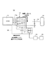
先ず、この発明の実施例に係る暖機制御装置を適用するディーゼルハイブリッド車両の概略構成について図1に基づいて説明する。ここで、図1は、ディーゼルハイブリッド車両の概略構成を示す模式図である。 First, a schematic configuration of a diesel hybrid vehicle to which a warm-up control device according to an embodiment of the present invention is applied will be described with reference to FIG. Here, FIG. 1 is a schematic diagram showing a schematic configuration of a diesel hybrid vehicle.
図1に示すように、ディーゼルハイブリッド車両(ハイブリッド車両)10には、走行駆動源としてのディーゼルエンジン(エンジン)11が設けられている。なお、図示を省略するが、このディーゼルエンジン11は、コモンレール方式の燃料噴射システム、排気ガス圧力を利用して吸気量を増大させるターボ過給機、バルブの開閉動作タイミングを可変制御する可変バルブタイミング機構等を備えている。
As shown in FIG. 1, a diesel hybrid vehicle (hybrid vehicle) 10 is provided with a diesel engine (engine) 11 as a travel drive source. Although not shown, the
また、図示を省略するが、ディーゼルエンジン11の排気通路には、排気ガス中の粒子状物質および窒素酸化物(NOx)を浄化するために、吸蔵還元型NOx触媒を担持したパティキュレートフィルタや、排気ガスの一部を吸気系に還流させる排気ガス再循環装置を備えている。
Although not shown, in the exhaust passage of the
ディーゼルエンジン11で発生する駆動力は、自動変速可能な有段変速機(以下、MMT(マルチモードマニュアルトランスミッション)と記す)12、ドライブシャフト14およびディファレンシャルギヤ(図示せず)を介して駆動輪13に伝達されるようになっている。このMMT12は、走行状態に応じてギヤ段の変速操作をアクチュエータで電気的に自動制御するものである。
The driving force generated by the
ディーゼルエンジン11とMMT12間には、動力伝達の接離を行うクラッチ12aが備えられており、走行状態に応じて接離操作をアクチュエータで電気的に自動制御されるようになっている。
Between the
また、ディーゼルエンジン11は、このMMT12から指令される要求エンジントルクを出力するために、その燃料噴射量や吸入空気量等を制御されるように構成されている。ディーゼルエンジン11の要求燃料噴射量は、たとえば、エンジンの回転数およびアクセル開度からマップ等に基づいて決定され、燃料噴射が実行されるようになっている。
Further, the
また、駆動系歯車装置(ギヤトレーン)を一体化したモータジェネレータ(MG)17は、インバータ19を介し、充放電可能な二次電池であるバッテリ20と接続されている。このモータジェネレータ17は、走行駆動源であるモータとして機能する力行運転モードと、発電機として機能する回生運転モードとの2つの運転状態をとり得るように構成されている。
A motor generator (MG) 17 in which a drive system gear unit (gear train) is integrated is connected via an inverter 19 to a battery 20 that is a chargeable / dischargeable secondary battery. The
たとえば、モータジェネレータ17は、力行運転モードではバッテリ20からの電力供給を受けて、ドライブシャフト14を駆動するための動力を発生する。また、回生運転モードでは、モータジェネレータ17は、ディーゼルエンジン11あるいはドライブシャフト14から伝達される駆動力を電力に変換し、バッテリ20を充電する。
For example, the
モータジェネレータ17が力行運転モードあるいは回生運転モードのいずれかで運転されるかは、バッテリ20の充電量SOC(State of Charge)を勘案して決定される。
Whether the
また、図1中に破線で示す暖機手段30は、冷間運転時にモータジェネレータ17にて発生した熱をエンジン冷却水を利用して回収し、ディーゼルエンジン11およびMMT12の双方を暖機するために設けたものである。図1中の太線矢印は、モータジェネレータ(MG)17の廃熱により温められた冷却水の流れ方向と、ディーゼルエンジン11およびMMT12を循環し熱交換して冷えた冷却水の流れ方向を示している。
Further, the warming-up means 30 indicated by a broken line in FIG. 1 recovers heat generated by the
この暖機手段30は、エンジン冷却水がモータジェネレータ17とディーゼルエンジン11とMMT12とを循環してそれぞれ熱交換できるように配管構成されている。たとえば、図示を省略するが、ディーゼルエンジン11では、そのウォータジャケット内とオイルパンに設けた配管内を冷却水が流れるように配管構成されている。
The warming-up means 30 is configured by piping so that the engine coolant can circulate through the
また、MMT12では、冷却水が変速機オイルと熱交換できるように配管構成されている。そして、この配管系には、ポンプやバルブが適宜箇所に設けられ、冷間運転時のみに冷却水が循環するように制御される。
Further, the
また、この冷却水の温度は、ディーゼルエンジン11に設けられているエンジン水温センサ(図示せず)によって検出され、その検出信号から、エンジン暖機判定手段としての図示しない電子制御ユニット(以下、ECUと称する)によって暖機状態が判断されるようになっている。
The temperature of the cooling water is detected by an engine water temperature sensor (not shown) provided in the
また、このECUは、後述するように、バッテリ充電量SOCおよびドライバ要求出力(車両要求出力)に応じてモータジェネレータ17の出力とディーゼルエンジン11の出力との分担比率を制御する分担比率制御手段でもある。
Further, as will be described later, this ECU is also a sharing ratio control means for controlling a sharing ratio between the output of the
このようにECUは、上記エンジン暖機判定手段と上記分担比率制御手段とを備える暖機制御装置として機能するとともに、車両全体の基本制御を実行する制御装置として機能するものである。 As described above, the ECU functions as a warm-up control device including the engine warm-up determination unit and the sharing ratio control unit, and also functions as a control device that executes basic control of the entire vehicle.
以上のように構成されたディーゼルハイブリッド車両10は、上記ECUによって各種センサからの出力情報に基づいて以下のように基本制御され、種々の状態で走行することができる。
The
ディーゼルハイブリッド車両10の冷間時における暖機制御については後述する。また、定常運転時には、通常は、ディーゼルエンジン11がドライブシャフト14の要求出力とほぼ等しい出力を発生するように運転される。このとき、ディーゼルエンジン11の出力のほぼすべてがドライブシャフト14に伝えられる。
The warm-up control when the
一方、バッテリ20の充電量SOCが予め定められた基準値以下に低下している場合には、ディーゼルエンジン11がドライブシャフト14の要求出力以上の出力で運転され、その余剰動力の一部はモータジェネレータ17によって電力として回生され、バッテリ20の充電に利用される。
On the other hand, when the charge amount SOC of the battery 20 is reduced to a predetermined reference value or less, the
そして、ディーゼルエンジン11の出力トルクが不足する場合には、バッテリ20の充電量SOCに応じてモータジェネレータ17によって不足分のトルクがアシストされ、必要トルクが確保される。
When the output torque of the
なお、上記ディーゼルハイブリッド車両10は、燃料の節約と排気エミッションの低減を図るために、いわゆるエコラン(エコノミー&エコロジーランニング)制御もなされる。たとえば、交差点における信号待ち等でディーゼルハイブリッド車両10が停車した場合に、所定の停止条件下でディーゼルエンジン11を自動停止させ、その後、所定の再始動条件下(たとえば、アクセルペダルを踏み込んだとき)でディーゼルエンジン11を再始動させる制御もなされる。
The
以上が本発明に係るディーゼルハイブリッド車両10の基本構成および基本制御動作である。
The above is the basic configuration and basic control operation of the
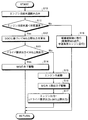
つぎに、本発明の要部であるディーゼルハイブリッド車両10の暖機制御方法について図2に基づいて図1、図3〜図5を参照しつつ説明する。以下の制御は、上記ECUによって実行されるものである。
Next, a warm-up control method for the
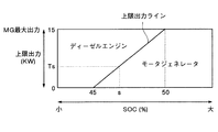
ここで、図2は、ディーゼルハイブリッド車両の暖機制御方法を示すフローチャートである。なお、図2中では、モータジェネレータ17をMGと略記してある。また、図3は、冷間時のバッテリ充電量SOCに応じたモータジェネレータ17の上限出力を示すマップであり、最大出力15KWのモータジェネレータ17を例にしたものである。
Here, FIG. 2 is a flowchart showing a warm-up control method for the diesel hybrid vehicle. In FIG. 2, the
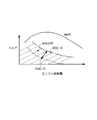
また、図4は、冷間時のバッテリ充電量SOCに応じたモータジェネレータ17の上限出力を示すマップであり、ディーゼルエンジン11による出力分担例を併記したものである。図5は、冷間時のバッテリ充電量SOCに応じたモータジェネレータ17の力行運転領域を示す説明図である。
FIG. 4 is a map showing the upper limit output of the
図2に示すように、先ず、上記エンジン水温センサによって検出されたエンジン冷却水温を読み込む(ステップS10)。つぎに、ディーゼルエンジン11が暖機状態であるか否かを判断するために、読み込まれたエンジン冷却水温が所定の温度(たとえば、60℃)未満であるか否かを判断する(ステップS11)。
As shown in FIG. 2, first, the engine coolant temperature detected by the engine coolant temperature sensor is read (step S10). Next, in order to determine whether or not the
エンジン冷却水温が所定の温度未満であるならば(ステップS11肯定)、冷間始動時等の冷間時であると判断できるので、つぎのステップS12以降の暖機制御を実施する。すなわち、この暖機制御では、モータジェネレータ17の駆動時の廃熱を暖機手段30によって回収してディーゼルエンジン11およびMMT12の双方を暖機するので、バッテリ充電量SOCに応じたモータジェネレータ17の上限出力を考慮する必要がある。
If the engine coolant temperature is lower than the predetermined temperature (Yes at step S11), it can be determined that the engine is cold such as at the time of cold start, and therefore, warm-up control after the next step S12 is performed. That is, in this warm-up control, the waste heat generated when the
そこで、図3および図4に示すマップを用い、バッテリ充電量SOCに基づいてモータジェネレータ17の上限出力を算出する(ステップS12)。すなわち、図3および図4に示すように、たとえば、モータジェネレータ17の最大出力が15KWであり、バッテリ充電量SOCが50%以上である場合には、当該最大出力である15KWを上限出力とする。なお、バッテリ充電量SOCがたとえば45%未満である場合には、バッテリ20の保護のため、モータジェネレータ17の上限出力を0KWとし、駆動させないようにしてある。
Therefore, the upper limit output of the
また、バッテリ充電量SOCが45%〜50%の範囲内にある場合は、図4に示すように、上記0〜15KWを当該バッテリ充電量SOCに応じて比例配分した上限出力とする。たとえば、バッテリ充電量SOCがs(%)である場合には、上限出力ライン上のTs(KW)を上限出力とする。 Further, when the battery charge amount SOC is in the range of 45% to 50%, as shown in FIG. 4, the above 0 to 15 kW is set as the upper limit output proportionally distributed according to the battery charge amount SOC. For example, when the battery charge amount SOC is s (%), Ts (KW) on the upper limit output line is set as the upper limit output.
つぎに、ドライバ要求出力(車両要求出力)がモータジェネレータ17の上限出力未満であるか否かを判断する(ステップS13)。ドライバ要求出力がモータジェネレータ17の上限出力未満であるならば(ステップS13肯定)、モータジェネレータ17のみを当該ドライバ要求出力で駆動し(ステップS14)、上記ステップS10に戻る。
Next, it is determined whether the driver request output (vehicle request output) is less than the upper limit output of the motor generator 17 (step S13). If the driver request output is less than the upper limit output of the motor generator 17 (Yes at Step S13), only the
このときモータジェネレータ17では多量の熱が発生するが、この熱は暖機手段30の冷却水と熱交換される。すなわち、モータジェネレータ17は冷やされ、暖機手段30の冷却水は温められる。温められた冷却水は、ディーゼルエンジン11に送られ、上記ウォータジャケットおよびオイルパン内に設けた配管を流れることにより、エンジン各部とエンジンオイルを温める。
At this time, a large amount of heat is generated in the
そして、ディーゼルエンジン11を経た冷却水は、MMT12に送られ、変速機オイルを温め、当該オイルによりMMT12各部が温められる。ディーゼルエンジン11およびMMT12と熱交換して冷えた冷却水は、再びモータジェネレータ17に戻り、モータジェネレータ17で発生する熱により温められる。
And the cooling water which passed through the
このようにして暖機手段30の冷却水は、冷間時にモータジェネレータ17とディーゼルエンジン11とMMT12とを循環して熱交換するので、ディーゼルエンジン11およびMMT12の早期暖機が図られる。
In this way, the cooling water of the warm-up means 30 is circulated through the
一方、ドライバ要求出力がモータジェネレータ17の上限出力を超えるならば(ステップS13否定)、モータジェネレータ17のみの駆動ではトルク不足となるので、この不足分のトルクを補うべく、モータジェネレータ17とディーゼルエンジン11の出力分担比率を設定して、ディーゼルエンジン11を駆動する必要がある。
On the other hand, if the driver request output exceeds the upper limit output of the motor generator 17 (No at Step S13), the drive with only the
そこで、ディーゼルエンジン11を始動するとともに(ステップS15)、モータジェネレータ17を上記ステップS12で算出された上限出力で駆動し(ステップS16)ディーゼルエンジン11を、上記ドライバ要求出力からモータジェネレータ17の上限出力を差し引いた出力で駆動し(ステップS17)、上記ステップS10に戻る。
Accordingly, the
たとえば、図4に示すように、ドライバ要求出力が、モータジェネレータ17の最大出力である15KWであり、その時のバッテリ充電量SOCがs(%)である場合には、モータジェネレータ17の上限出力はTs(KW)となり、ディーゼルエンジン11が分担する出力は、(15−Ts)KWとなる。
For example, as shown in FIG. 4, when the driver request output is 15 kW which is the maximum output of the
以上のように、エンジンオイルの粘度が高い冷間時では、モータジェネレータ17にてドライバ要求出力のほとんどを分担することにより、燃費悪化条件下でのディーゼルエンジン11の運転を可能な限り控えており、これにより暖機手段30による暖機性向上と燃費の向上とを両立させるようにしている。
As described above, when the engine oil viscosity is high and cold, the
なお、この冷間時でのモータジェネレータ17の力行運転領域の一例を図5に示す。この図5では、モータジェネレータ17の力行運転領域の上限境界線を、バッテリ充電量SOCが大きい場合には一点鎖線で示し、バッテリ充電量SOCが小さい場合には破線で示してある。ハッチングは、バッテリ充電量SOCが大きい場合におけるモータジェネレータ17のみによる力行運転領域を示している。また、バッテリ充電量SOCが大〜小の矢印の範囲にある場合には、ドライバ要求出力に応じてディーゼルエンジン11も出力を分担することとなる。
An example of the power running region of the
エンジン冷却水温が所定の温度を超えているならば(ステップS11否定)、既に暖機が完了していると判断できるので、暖機後の通常制御に移行すればよい(ステップS18)。すなわち、軽負荷運転領域ではモータジェネレータ17により走行し、中高負荷運転領域では、エンジン走行する。
If the engine coolant temperature exceeds the predetermined temperature (No at Step S11), it can be determined that the warm-up has already been completed, and therefore it is sufficient to shift to the normal control after the warm-up (Step S18). That is, the
以上のように、この実施例に係るハイブリッド車両の暖機制御装置によれば、エンジンオイルの粘度が高い冷間時では、主としてモータジェネレータ17により要求出力のほとんどを分担することにより、燃費悪化条件下でのディーゼルエンジン11の運転を控えることができる。したがって、冷間時の燃費悪化を抑制することができる。
As described above, according to the warm-up control device for a hybrid vehicle according to this embodiment, when the engine oil has a high viscosity, the
また、モータジェネレータ17からの廃熱を回収して、ディーゼルエンジン11およびMMT12の暖機に利用しているので、エンジンオイル等の機関各部や変速機オイル等のMMT12各部の暖機を早期に完了させ、低フリクション、低冷却損失な状態でエンジン運転に移行することができる。また、早期の暖機完了により、ディーゼルエンジン11のスモークの発生を抑制することができる。
In addition, since the waste heat from the
なお、上記実施例においては、ディーゼルエンジン11を走行駆動源とするハイブリッド車両について本発明を適用して説明したが、これに限定されず、ガソリンエンジンを走行駆動源とするハイブリッド車両に適用してもよい。
In the above embodiment, the present invention is applied to a hybrid vehicle using the
また、有段自動変速機(MMT12)を備えたハイブリッド車両について本発明を適用して説明したが、これに限定されず、自動変速機(AT)や手動変速機(MT)、無段変速機(CVT)を備えたハイブリッド車両に適用してもよい。 Further, the present invention is applied to the hybrid vehicle including the stepped automatic transmission (MMT12). However, the present invention is not limited to this, and the automatic transmission (AT), the manual transmission (MT), the continuously variable transmission is not limited thereto. You may apply to the hybrid vehicle provided with (CVT).
また、暖機手段30は、ディーゼルエンジン11とMMT12の双方を暖機するものとして説明したが、これに限定されず、ディーゼルエンジン11のみを暖機するように構成してもよい。
Moreover, although the warm-up means 30 demonstrated as what warms up both the
なお、最大出力の小さいモータジェネレータであって、発熱量が比較的少なくその廃熱利用の効果が少ない場合には、必ずしも上記暖機手段30を設けなくてもよい。その場合は、分担比率制御手段としてのECUが、暖機完了が判定されるまでの間、上述したようにモータジェネレータの出力が大きくエンジン出力が小さくなるように分担比率を制御する構成のみを採用すればよい。 When the motor generator has a small maximum output and the amount of heat generated is relatively small and the effect of using the waste heat is small, the warm-up means 30 is not necessarily provided. In that case, only the configuration in which the ECU as the sharing ratio control unit controls the sharing ratio so that the output of the motor generator is large and the engine output is small as described above until the warm-up completion is determined. do it.
以上のように、この発明に係るハイブリッド車両の暖機制御装置は、パラレル式のハイブリッド車両に有用であり、特に、エンジン冷間時の暖機性を向上させ、燃費悪化の抑制を目指すハイブリッド車両に適している。 As described above, the warm-up control device for a hybrid vehicle according to the present invention is useful for a parallel-type hybrid vehicle. In particular, the hybrid vehicle aims to improve warm-up when the engine is cold and suppress deterioration in fuel consumption. Suitable for
10 ディーゼルハイブリッド車両(ハイブリッド車両)
11 ディーゼルエンジン(エンジン)
12 MMT(変速機)
17 モータジェネレータ
20 バッテリ
30 暖機手段
SOC バッテリ充電量
10 Diesel hybrid vehicle (hybrid vehicle)
11 Diesel engine (engine)
12 MMT (transmission)
17 Motor generator 20
Claims (2)
有段または無段の変速機と、
前記エンジン出力による発電またはバッテリ電力による前記エンジン出力のアシストを行うモータジェネレータと、
を備えたハイブリッド車両の暖機制御装置であって、
前記暖機制御装置は、
前記エンジンの暖機状態を判定するエンジン暖機判定手段と、
前記バッテリの充電量および車両要求出力に応じて前記モータジェネレータの出力と前記エンジンの出力との分担比率を制御する分担比率制御手段と、
を備え、
前記分担比率制御手段は、前記エンジン暖機判定手段により暖機完了が判定されるまでの間、前記モータジェネレータの出力が大きく前記エンジン出力が小さくなるように分担比率を制御することを特徴とするハイブリッド車両の暖機制御装置。 An engine as a travel drive source;
A stepped or continuously variable transmission;
A motor generator for assisting the engine output by power generation or battery power by the engine output;
A warm-up control device for a hybrid vehicle equipped with
The warm-up control device
Engine warm-up determination means for determining a warm-up state of the engine;
A sharing ratio control means for controlling a sharing ratio between the output of the motor generator and the output of the engine in accordance with the amount of charge of the battery and the required vehicle output;
With
The share ratio control means controls the share ratio so that the output of the motor generator is large and the engine output is small until the warm-up completion is determined by the engine warm-up determination means. A warm-up control device for hybrid vehicles.
Priority Applications (1)
| Application Number | Priority Date | Filing Date | Title |
|---|---|---|---|
| JP2004115522A JP2005299469A (en) | 2004-04-09 | 2004-04-09 | Hybrid vehicle warm-up control device |
Applications Claiming Priority (1)
| Application Number | Priority Date | Filing Date | Title |
|---|---|---|---|
| JP2004115522A JP2005299469A (en) | 2004-04-09 | 2004-04-09 | Hybrid vehicle warm-up control device |
Publications (1)
| Publication Number | Publication Date |
|---|---|
| JP2005299469A true JP2005299469A (en) | 2005-10-27 |
Family
ID=35331330
Family Applications (1)
| Application Number | Title | Priority Date | Filing Date |
|---|---|---|---|
| JP2004115522A Pending JP2005299469A (en) | 2004-04-09 | 2004-04-09 | Hybrid vehicle warm-up control device |
Country Status (1)
| Country | Link |
|---|---|
| JP (1) | JP2005299469A (en) |
Cited By (21)
| Publication number | Priority date | Publication date | Assignee | Title |
|---|---|---|---|---|
| JP2008126809A (en) * | 2006-11-20 | 2008-06-05 | Toyota Motor Corp | POWER OUTPUT DEVICE, VEHICLE MOUNTING THE SAME, AND METHOD FOR CONTROLLING INTERNAL COMBUSTION ENGINE |
| JP2011032890A (en) * | 2009-07-30 | 2011-02-17 | Honda Motor Co Ltd | Control device for vehicle |
| JP2013001201A (en) * | 2011-06-14 | 2013-01-07 | Toyota Motor Corp | Control device of vehicle drive device |
| JP2013112126A (en) * | 2011-11-28 | 2013-06-10 | Toyota Motor Corp | Controller for vehicle |
| JP2013203287A (en) * | 2012-03-29 | 2013-10-07 | Denso Corp | Control device for hybrid vehicle |
| JP2014196013A (en) * | 2013-03-29 | 2014-10-16 | トヨタ自動車株式会社 | Vehicle |
| CN104295429A (en) * | 2013-07-16 | 2015-01-21 | 福特全球技术公司 | Hybrid vehicle engine warm-up |
| US9187083B2 (en) | 2009-09-16 | 2015-11-17 | Polaris Industries Inc. | System and method for charging an on-board battery of an electric vehicle |
| US9802605B2 (en) | 2009-09-16 | 2017-10-31 | Swissauto Powersport Llc | Electric vehicle and on-board battery charging apparatus therefor |
| US10300786B2 (en) | 2014-12-19 | 2019-05-28 | Polaris Industries Inc. | Utility vehicle |
| US10744868B2 (en) | 2016-06-14 | 2020-08-18 | Polaris Industries Inc. | Hybrid utility vehicle |
| US10780770B2 (en) | 2018-10-05 | 2020-09-22 | Polaris Industries Inc. | Hybrid utility vehicle |
| US11370266B2 (en) | 2019-05-16 | 2022-06-28 | Polaris Industries Inc. | Hybrid utility vehicle |
| JP2023165455A (en) * | 2022-05-06 | 2023-11-16 | トヨタ自動車株式会社 | Vehicle control device |
| US12172518B2 (en) | 2019-04-30 | 2024-12-24 | Polaris Industries Inc. | Vehicle |
| US12187127B2 (en) | 2020-05-15 | 2025-01-07 | Polaris Industries Inc. | Off-road vehicle |
| US12214654B2 (en) | 2021-05-05 | 2025-02-04 | Polaris Industries Inc. | Exhaust assembly for a utility vehicle |
| US12385429B2 (en) | 2022-06-13 | 2025-08-12 | Polaris Industries Inc. | Powertrain for a utility vehicle |
| US12384464B2 (en) | 2020-05-15 | 2025-08-12 | Polaris Industries Inc. | Off-road vehicle |
| US12485981B2 (en) | 2021-03-24 | 2025-12-02 | Polaris Industries Inc. | Electric recreational vehicle |
| US12552246B2 (en) | 2015-05-15 | 2026-02-17 | Polaris Industries Inc. | Utility vehicle |
Citations (5)
| Publication number | Priority date | Publication date | Assignee | Title |
|---|---|---|---|---|
| JPH1122466A (en) * | 1997-07-04 | 1999-01-26 | Nissan Motor Co Ltd | Hybrid electric vehicle cooling system |
| JP2001073765A (en) * | 1999-08-31 | 2001-03-21 | Suzuki Motor Corp | Hybrid vehicle cooling system |
| JP2001206050A (en) * | 1999-12-17 | 2001-07-31 | Robert Bosch Gmbh | Heat exchange device for vehicle heater with hybrid drive |
| JP2001317384A (en) * | 2000-04-28 | 2001-11-16 | Toyota Motor Corp | Internal combustion engine control device for hybrid vehicle |
| JP2003262127A (en) * | 2002-01-04 | 2003-09-19 | Visteon Global Technologies Inc | Power train heat control system and method for hybrid vehicle |
-
2004
- 2004-04-09 JP JP2004115522A patent/JP2005299469A/en active Pending
Patent Citations (5)
| Publication number | Priority date | Publication date | Assignee | Title |
|---|---|---|---|---|
| JPH1122466A (en) * | 1997-07-04 | 1999-01-26 | Nissan Motor Co Ltd | Hybrid electric vehicle cooling system |
| JP2001073765A (en) * | 1999-08-31 | 2001-03-21 | Suzuki Motor Corp | Hybrid vehicle cooling system |
| JP2001206050A (en) * | 1999-12-17 | 2001-07-31 | Robert Bosch Gmbh | Heat exchange device for vehicle heater with hybrid drive |
| JP2001317384A (en) * | 2000-04-28 | 2001-11-16 | Toyota Motor Corp | Internal combustion engine control device for hybrid vehicle |
| JP2003262127A (en) * | 2002-01-04 | 2003-09-19 | Visteon Global Technologies Inc | Power train heat control system and method for hybrid vehicle |
Cited By (30)
| Publication number | Priority date | Publication date | Assignee | Title |
|---|---|---|---|---|
| JP2008126809A (en) * | 2006-11-20 | 2008-06-05 | Toyota Motor Corp | POWER OUTPUT DEVICE, VEHICLE MOUNTING THE SAME, AND METHOD FOR CONTROLLING INTERNAL COMBUSTION ENGINE |
| JP2011032890A (en) * | 2009-07-30 | 2011-02-17 | Honda Motor Co Ltd | Control device for vehicle |
| US9187083B2 (en) | 2009-09-16 | 2015-11-17 | Polaris Industries Inc. | System and method for charging an on-board battery of an electric vehicle |
| US9802605B2 (en) | 2009-09-16 | 2017-10-31 | Swissauto Powersport Llc | Electric vehicle and on-board battery charging apparatus therefor |
| JP2013001201A (en) * | 2011-06-14 | 2013-01-07 | Toyota Motor Corp | Control device of vehicle drive device |
| JP2013112126A (en) * | 2011-11-28 | 2013-06-10 | Toyota Motor Corp | Controller for vehicle |
| JP2013203287A (en) * | 2012-03-29 | 2013-10-07 | Denso Corp | Control device for hybrid vehicle |
| JP2014196013A (en) * | 2013-03-29 | 2014-10-16 | トヨタ自動車株式会社 | Vehicle |
| US20150025721A1 (en) * | 2013-07-16 | 2015-01-22 | Ford Global Technologies, Llc | Hybrid vehicle engine warm-up |
| CN104295429A (en) * | 2013-07-16 | 2015-01-21 | 福特全球技术公司 | Hybrid vehicle engine warm-up |
| US10300786B2 (en) | 2014-12-19 | 2019-05-28 | Polaris Industries Inc. | Utility vehicle |
| US10800250B2 (en) | 2014-12-19 | 2020-10-13 | Polaris Industries Inc. | Utility vehicle |
| US11884148B2 (en) | 2014-12-19 | 2024-01-30 | Polaris Industries Inc. | Utility vehicle |
| US12122228B2 (en) | 2014-12-19 | 2024-10-22 | Polaris Industries Inc. | Utility vehicle |
| US12552246B2 (en) | 2015-05-15 | 2026-02-17 | Polaris Industries Inc. | Utility vehicle |
| US10744868B2 (en) | 2016-06-14 | 2020-08-18 | Polaris Industries Inc. | Hybrid utility vehicle |
| US10780770B2 (en) | 2018-10-05 | 2020-09-22 | Polaris Industries Inc. | Hybrid utility vehicle |
| US12420624B2 (en) | 2018-10-05 | 2025-09-23 | Polaris Industries, Inc. | Hybrid utility vehicle |
| US12172518B2 (en) | 2019-04-30 | 2024-12-24 | Polaris Industries Inc. | Vehicle |
| US11370266B2 (en) | 2019-05-16 | 2022-06-28 | Polaris Industries Inc. | Hybrid utility vehicle |
| US12194808B2 (en) | 2019-05-16 | 2025-01-14 | Polaris Industries Inc. | Hybrid utility vehicle |
| US12311728B2 (en) | 2019-05-16 | 2025-05-27 | Polaris Industries Inc. | Hybrid utility vehicle |
| US12337690B2 (en) | 2020-05-15 | 2025-06-24 | Polaris Industries Inc. | Off-road vehicle |
| US12384464B2 (en) | 2020-05-15 | 2025-08-12 | Polaris Industries Inc. | Off-road vehicle |
| US12187127B2 (en) | 2020-05-15 | 2025-01-07 | Polaris Industries Inc. | Off-road vehicle |
| US12485981B2 (en) | 2021-03-24 | 2025-12-02 | Polaris Industries Inc. | Electric recreational vehicle |
| US12214654B2 (en) | 2021-05-05 | 2025-02-04 | Polaris Industries Inc. | Exhaust assembly for a utility vehicle |
| JP7740121B2 (en) | 2022-05-06 | 2025-09-17 | トヨタ自動車株式会社 | Vehicle control device |
| JP2023165455A (en) * | 2022-05-06 | 2023-11-16 | トヨタ自動車株式会社 | Vehicle control device |
| US12385429B2 (en) | 2022-06-13 | 2025-08-12 | Polaris Industries Inc. | Powertrain for a utility vehicle |
Similar Documents
| Publication | Publication Date | Title |
|---|---|---|
| JP2005299469A (en) | Hybrid vehicle warm-up control device | |
| KR101046550B1 (en) | Hybrid system control unit and hybrid system control method | |
| US8333066B2 (en) | Catalyst temperature increasing apparatus for hybrid vehicle | |
| JP4552921B2 (en) | Hybrid vehicle and control method thereof | |
| CN113646519A (en) | System and method for maintaining thermal aftertreatment while engine is idling | |
| JP2004052672A (en) | Hybrid vehicle and control method thereof | |
| JP3984964B2 (en) | Control method of hybrid vehicle | |
| JP2010038147A (en) | Engine exhaust emission control system | |
| JP5212276B2 (en) | Hybrid car | |
| JP3851296B2 (en) | Control method of diesel hybrid vehicle | |
| JP4080457B2 (en) | Filter clogging suppression control method for diesel hybrid vehicle | |
| JP2009127512A (en) | Vehicle control device | |
| JP4086005B2 (en) | Warm-up control method of low compression ratio engine in diesel hybrid vehicle | |
| JP3894153B2 (en) | Diesel hybrid vehicle engine start control method | |
| CN114412651B (en) | Hybrid vehicle and control method and control device for ignition of catalyst thereof | |
| JP4099160B2 (en) | Motor torque control method for hybrid vehicle | |
| JP2005325804A (en) | Control method for starting hybrid vehicle | |
| JP2005330844A (en) | Vacuum pump control method and vacuum pump mounting structure for diesel hybrid vehicle | |
| JP3905515B2 (en) | Regeneration control method of exhaust purification device in diesel hybrid vehicle | |
| JP3997944B2 (en) | Method for reducing gear rattling noise of drive train gear unit in hybrid vehicle | |
| JP2005325805A (en) | Automatic engine stop / start control system for hybrid vehicles | |
| JPH0779503A (en) | Battery warm-up device for hybrid vehicles | |
| JP7276121B2 (en) | vehicle controller | |
| JP2006220045A (en) | Control method for vehicle deceleration | |
| JP4080460B2 (en) | Control method for engine start of hybrid vehicle |
Legal Events
| Date | Code | Title | Description |
|---|---|---|---|
| A621 | Written request for application examination |
Free format text: JAPANESE INTERMEDIATE CODE: A621 Effective date: 20070312 |
|
| A131 | Notification of reasons for refusal |
Free format text: JAPANESE INTERMEDIATE CODE: A131 Effective date: 20070807 |
|
| A02 | Decision of refusal |
Free format text: JAPANESE INTERMEDIATE CODE: A02 Effective date: 20080108 |