JP4062028B2 - Assembly structure of heat exchanger and shroud - Google Patents
Assembly structure of heat exchanger and shroud Download PDFInfo
- Publication number
- JP4062028B2 JP4062028B2 JP2002272715A JP2002272715A JP4062028B2 JP 4062028 B2 JP4062028 B2 JP 4062028B2 JP 2002272715 A JP2002272715 A JP 2002272715A JP 2002272715 A JP2002272715 A JP 2002272715A JP 4062028 B2 JP4062028 B2 JP 4062028B2
- Authority
- JP
- Japan
- Prior art keywords
- shroud
- bracket
- heat exchanger
- radiator
- assembly structure
- Prior art date
- Legal status (The legal status is an assumption and is not a legal conclusion. Google has not performed a legal analysis and makes no representation as to the accuracy of the status listed.)
- Expired - Fee Related
Links
Images


Classifications
-
- F—MECHANICAL ENGINEERING; LIGHTING; HEATING; WEAPONS; BLASTING
- F28—HEAT EXCHANGE IN GENERAL
- F28F—DETAILS OF HEAT-EXCHANGE AND HEAT-TRANSFER APPARATUS, OF GENERAL APPLICATION
- F28F9/00—Casings; Header boxes; Auxiliary supports for elements; Auxiliary members within casings
- F28F9/001—Casings in the form of plate-like arrangements; Frames enclosing a heat exchange core
- F28F9/002—Casings in the form of plate-like arrangements; Frames enclosing a heat exchange core with fastening means for other structures
-
- F—MECHANICAL ENGINEERING; LIGHTING; HEATING; WEAPONS; BLASTING
- F28—HEAT EXCHANGE IN GENERAL
- F28D—HEAT-EXCHANGE APPARATUS, NOT PROVIDED FOR IN ANOTHER SUBCLASS, IN WHICH THE HEAT-EXCHANGE MEDIA DO NOT COME INTO DIRECT CONTACT
- F28D1/00—Heat-exchange apparatus having stationary conduit assemblies for one heat-exchange medium only, the media being in contact with different sides of the conduit wall, in which the other heat-exchange medium is a large body of fluid, e.g. domestic or motor car radiators
- F28D1/02—Heat-exchange apparatus having stationary conduit assemblies for one heat-exchange medium only, the media being in contact with different sides of the conduit wall, in which the other heat-exchange medium is a large body of fluid, e.g. domestic or motor car radiators with heat-exchange conduits immersed in the body of fluid
- F28D1/04—Heat-exchange apparatus having stationary conduit assemblies for one heat-exchange medium only, the media being in contact with different sides of the conduit wall, in which the other heat-exchange medium is a large body of fluid, e.g. domestic or motor car radiators with heat-exchange conduits immersed in the body of fluid with tubular conduits
- F28D1/0408—Multi-circuit heat exchangers, e.g. integrating different heat exchange sections in the same unit or heat exchangers for more than two fluids
- F28D1/0426—Multi-circuit heat exchangers, e.g. integrating different heat exchange sections in the same unit or heat exchangers for more than two fluids with units having particular arrangement relative to the large body of fluid, e.g. with interleaved units or with adjacent heat exchange units in common air flow or with units extending at an angle to each other or with units arranged around a central element
- F28D1/0435—Combination of units extending one behind the other
-
- F—MECHANICAL ENGINEERING; LIGHTING; HEATING; WEAPONS; BLASTING
- F01—MACHINES OR ENGINES IN GENERAL; ENGINE PLANTS IN GENERAL; STEAM ENGINES
- F01P—COOLING OF MACHINES OR ENGINES IN GENERAL; COOLING OF INTERNAL-COMBUSTION ENGINES
- F01P5/00—Pumping cooling-air or liquid coolants
- F01P5/02—Pumping cooling-air; Arrangements of cooling-air pumps, e.g. fans or blowers
- F01P2005/025—Pumping cooling-air; Arrangements of cooling-air pumps, e.g. fans or blowers using two or more air pumps
-
- F—MECHANICAL ENGINEERING; LIGHTING; HEATING; WEAPONS; BLASTING
- F01—MACHINES OR ENGINES IN GENERAL; ENGINE PLANTS IN GENERAL; STEAM ENGINES
- F01P—COOLING OF MACHINES OR ENGINES IN GENERAL; COOLING OF INTERNAL-COMBUSTION ENGINES
- F01P2070/00—Details
- F01P2070/50—Details mounting fans to heat-exchangers
-
- F—MECHANICAL ENGINEERING; LIGHTING; HEATING; WEAPONS; BLASTING
- F01—MACHINES OR ENGINES IN GENERAL; ENGINE PLANTS IN GENERAL; STEAM ENGINES
- F01P—COOLING OF MACHINES OR ENGINES IN GENERAL; COOLING OF INTERNAL-COMBUSTION ENGINES
- F01P2070/00—Details
- F01P2070/52—Details mounting heat-exchangers
-
- F—MECHANICAL ENGINEERING; LIGHTING; HEATING; WEAPONS; BLASTING
- F28—HEAT EXCHANGE IN GENERAL
- F28D—HEAT-EXCHANGE APPARATUS, NOT PROVIDED FOR IN ANOTHER SUBCLASS, IN WHICH THE HEAT-EXCHANGE MEDIA DO NOT COME INTO DIRECT CONTACT
- F28D21/00—Heat-exchange apparatus not covered by any of the groups F28D1/00 - F28D20/00
- F28D2021/0019—Other heat exchangers for particular applications; Heat exchange systems not otherwise provided for
- F28D2021/008—Other heat exchangers for particular applications; Heat exchange systems not otherwise provided for for vehicles
- F28D2021/0084—Condensers
-
- F—MECHANICAL ENGINEERING; LIGHTING; HEATING; WEAPONS; BLASTING
- F28—HEAT EXCHANGE IN GENERAL
- F28D—HEAT-EXCHANGE APPARATUS, NOT PROVIDED FOR IN ANOTHER SUBCLASS, IN WHICH THE HEAT-EXCHANGE MEDIA DO NOT COME INTO DIRECT CONTACT
- F28D21/00—Heat-exchange apparatus not covered by any of the groups F28D1/00 - F28D20/00
- F28D2021/0019—Other heat exchangers for particular applications; Heat exchange systems not otherwise provided for
- F28D2021/008—Other heat exchangers for particular applications; Heat exchange systems not otherwise provided for for vehicles
- F28D2021/0091—Radiators
- F28D2021/0094—Radiators for recooling the engine coolant
-
- F—MECHANICAL ENGINEERING; LIGHTING; HEATING; WEAPONS; BLASTING
- F28—HEAT EXCHANGE IN GENERAL
- F28F—DETAILS OF HEAT-EXCHANGE AND HEAT-TRANSFER APPARATUS, OF GENERAL APPLICATION
- F28F2275/00—Fastening; Joining
- F28F2275/08—Fastening; Joining by clamping or clipping
- F28F2275/085—Fastening; Joining by clamping or clipping with snap connection
Landscapes
- Engineering & Computer Science (AREA)
- Physics & Mathematics (AREA)
- Thermal Sciences (AREA)
- Mechanical Engineering (AREA)
- General Engineering & Computer Science (AREA)
- Cooling, Air Intake And Gas Exhaust, And Fuel Tank Arrangements In Propulsion Units (AREA)
- Details Of Heat-Exchange And Heat-Transfer (AREA)
- Air-Conditioning For Vehicles (AREA)
Description
【0001】
【発明の属する技術分野】
本発明は、送風機を熱交換器に固定するためのシュラウドと熱交換器との組み付け構造に関するもので、車両に適用して有効である。
【0002】
【従来の技術】
従来は、ラジエータ及びシュラウドを車両取付用のブラケットに固定した後、このラジエータとシュラウド(送風機を含む。)とが一体化されたモジュールを車両に組み付けていた(例えば、特許文献1参照)。
【0003】
【特許文献1】
特開平11−142084号公報
【0004】
【発明が解決しようとする課題】
しかし、特許文献1に記載の発明では、ラジエータにブラケットを固定した後、シュラウドをブラケットに固定する必要があり、必ずしも、組み付け作業性及び分解作業性が高くない。
【0005】
本発明は、上記点に鑑み、第1には、従来と異なる新規な熱交換器及びシュラウドの組み付け構造を提供し、第2には、熱交換器とシュラウドとの組み付け作業性を及び分解作業性を向上させることを目的とする。
【0006】
【課題を解決するための手段】
本発明は、上記目的を達成するために、請求項1に記載の発明では、熱交換器(1)に空気を送風する送風機(5)、送風機(5)を熱交換器(1)に固定するためのシュラウド(4)、熱交換器(1)を車両ボディに取り付けるためのブラケット(3)を有し、熱交換器(1)及びシュラウド(4)の組み付け構造であって、ブラケット(3)とシュラウド(4)とは、ブラケット(3)の上端側に位置して上方向に突出する突起部(3b)により水平方向の変位が規制された状態で、車両ボディの一部により抑えられて鉛直方向の変位が規制され、さらに、シュラウド(4)の下端側は、ブラケット(3)に設けられた支持突起部(3j)にて支持されていることを特徴とする。
【0007】
これにより、熱交換器(1)に組み付けられたブラケット(3)の上にシュラウド(4)を被せるようにしてシュラウド(4)を熱交換器(1)に組み付けるとともに、車両ボディにてシュラウド(4)がブラケット(3)から脱落することを防止するので、熱交換器(1)とシュラウド(4)とを容易に組み付けることができる。
【0008】
したがって、熱交換器(1)とシュラウド(4)の組み付け作業性を及び分解作業性を向上させることができる。
【0012】
請求項2に記載の発明では、熱交換器(1)に空気を送風する送風機(5)、送風機(5)を熱交換器(1)に固定するためのシュラウド(4)、及び熱交換器(1)を車両ボディに取り付けるためのブラケット(3)を有し、熱交換器(1)及びシュラウド(4)の組み付け構造であって、ブラケット(3)とシュラウド(4)とは、ブラケット(3)の上端側に位置して上方向に延びる突起部(3b)により水平方向の変位が規制された状態で、ブラケット及びシュラウド(4)のうち少なくとも一方に設けられた締結手段(3h)により鉛直方向の変位が規制され、さらに、シュラウド(4)の下端側は、ブラケット(3)に設けられた支持突起部(3j)にて支持されていることを特徴とする。
【0013】
これにより、熱交換器(1)に組み付けられたブラケット(3)の上にシュラウド(4)を被せるようにしてシュラウド(4)を熱交換器(1)に組み付けるとともに、締結手段(3h)にてシュラウド(4)がブラケット(3)から脱落することを防止するので、熱交換器(1)とシュラウド(4)とを容易に組み付けることができる。
【0014】
したがって、熱交換器(1)とシュラウド(4)の組み付け作業性を及び分解作業性を向上させることができる。
【0018】
請求項3に記載の発明では、締結手段(3h)は、弾性変位可能な係止突起を有して構成されていることを特徴とするものである。
【0019】
請求項4に記載の発明では、ブラケット(3)に突起部(3b)が設けられ、かつ、シュラウド(4)には突起部(3b)が挿入される挿入穴(4a)が設けられていることを特徴とするものである。
【0020】
因みに、上記各手段の括弧内の符号は、後述する実施形態に記載の具体的手段との対応関係を示す一例である。
【0021】
【発明の実施の形態】
(第1実施形態)
本実施形態は、本発明に係る熱交換器とシュラウドとの組み付け構造を車両用ラジエータと車両用空調装置の室外熱交換器とが一体化されたクーリングモジュールの組み付け構造に適用したものである。
【0022】
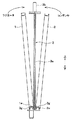
因みに、図1はクーリングモジュールを空気流れ下流側から見た斜視図であり、図2は図1のA部拡大図である。
【0023】
ラジエータ1はエンジン内を循環する冷却水と空気とを熱交換して冷却水を冷却するもので、凝縮器2(図1参照)は圧縮機から吐出した高圧冷媒を冷却凝縮させるものである。
【0024】
また、ラジエータ1と凝縮器2とは略同一構造を有しており、具体的には、図1に示すように、流体、つまりラジエータ1にあっては冷却水、凝縮器2にあっては冷媒が流れる複数本のチューブ1a及びチューブの外表面に接合されて空気との伝熱面積を増大させるフィン1bからなるコア部1c、チューブ1aの長手方向両端部にて複数本のチューブ1aに連通してチューブ1aの長手方向と略直交する方向に延びるヘッダタンク1d、並びにコア部1cの端部に位置してチューブ1aの長手方向と平行に延びてコア部1cを補強するインサート1e等からなるもので、本実施形態では、これらの部品を全てアルミニウム合金製としてろう接に一体化している。
【0025】
なお、図1では、凝縮器2のコア部が見えないため、チューブ、フィン、コア部、ヘッダタンク及びインサートの符号は、ラジエータ1に関するもののみ付した。
【0026】
因みに、「ろう接」とは、例えば「接続・接合技術」(東京電機大学出版局)に記載されているように、ろう材やはんだを用いて母材を溶融させないように接合する技術を言う。因みに、融点が450℃以上の溶加材を用いて接合するときをろう付けと言い、その際の溶加材をろう材と呼び、融点が450℃以下の溶加材を用いて接合するときをはんだ付けと言い、その際の溶加材をはんだと呼ぶ。
【0027】
また、ラジエータ1と凝縮器2とは、それぞれのコア面が所定の隙間を有して対向するように配置されているとともに、図2に示すように、ラジエータ1と凝縮器2と間に挟まれて配置されたブラケット3に固定されており、このブラケット3を介して車両ボディに取り付けられる。
【0028】
ブラケット3は、図3に示すように、ブラケット本体3a、取付ピン3b、取付ステー3c及び及び補強部3d等からなるもので、これら3a〜3dは、樹脂(例えば、ガラス繊維入りナイロン)にて一体成形されている。
【0029】
ここで、ブラケット本体3aは、ラジエータ1のヘッダタンク1d及び凝縮器2のヘッダタンクに対応する部位、つまりラジエータ1及び凝縮器2の端部に対応する部位にて上下方向に延びる帯板状のものであり、取付ステー部3cはブラケット本体3aの上下端にてラジエータ1及び凝縮器2のコア部側に突出する帯板状のものである。
【0030】
また、取付ステー部3cには、クーリングモジュール、つまりブラケット3により一体化されたラジエータ1及び凝縮器2を車両ボディに組み付けるための取付ピン3bが設けられており、この取付ピン3bは取付ステー部3cから上下方向に突出するピン状の突起部である。また、補強部3dは、取付ステー部3cの根元側に設けられて取付ステー部3cとブラケット本体3aとの結合部に発生するモーメントに対向する略三角状もので、この補強部3dには、コア面と直交する方向、つまり空気の流通方向に貫通する複数個の穴部3eが形成されている。
【0031】
なお、本実施形態では、穴部3eの形状を略三角状とすることにより、補強部3dをトラス構造とし、強度が大きく低下することを防止している。
【0032】
ところで、ラジエータ1の上端側は、図5に示すように、インサート1eに設けられた穴1fにブラケット3に設けられたスナップフィット3fを嵌合させることによりブラケット3に固定され、下端側は、図6に示すように、ブラケット3の下端側に形成された突起部3gとインサート1eの断面形状を略コの字状とすることにより形成された凹部とを嵌合させることによりブラケット3に固定される。
【0033】
因みに、スナップフィット3fとは、鍵状に形成された突起部の弾性変形を利用して着脱可能に2つの部材を締結固定する締結手段なすものであり、本実施形態では、スナップフィット3fは、ブラケット3に一体形成されている。
【0034】
なお、凝縮器2の上端側は、図4に示すように、ブラケット3の一部をインサート2eに嵌め込むことによりブラケット3に固定され、下端側は、ラジエータ1と同様に(図6参照)、突起部3gとインサート2eの凹部とを嵌合させることによりブラケット3に固定される。
【0035】
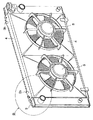
また、ファンシュラウド4の上端側は、図7、8に示すように、ファンシュラウド4に形成された穴部4a(図9、10参照)に取付ピン3bを挿入することによりファンシュラウド4がブラケット3に対して水平方向に変位することが規制されているとともに、図11に示すように、車両ボディの一部をなすアッパメンバ又はラジエータサポート6より抑えられて鉛直方向の変位が規制されている。
【0036】
なお、本実施形態では、ラジエータサポート6よる抑えに加えて、ブラケット3にスナップフィット3hを設けてブラケット3とファンシュラウド4とを係止固定し、クーリングモジュールを車両に組み付けた場合は勿論のこと、搬送途中等のクーリングモジュールを車両に組み付ける前段階においても、ブラケット3に対してファンシュラウド4がずれてしまうことを防止している。
【0037】
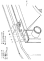
一方、ファンシュラウド4の上端側は、図9、10に示すように、ブラケット3に設けられた支持突起部3jにて支持されている。なお、支持突起部3jは、前端側に傘状のフランジ部を有するもので、ファンシュラウド4に設けられた凹状の溝部4b(図9参照)に支持突起部3jが嵌り込むことにより、ファンシュラウド4が下方側及び水平方向側に変位することが規制される。
【0038】
因みに、ファンシュラウド4とは、ラジエータ1等の熱交換器に冷却風を送風する送風機5(図9参照)を支持するものであり、本実施形態では、支持部材として機能に加えて、送風機5とラジエータ1の隙間を覆って送風機5にて誘起された空気流が送風機5とラジエータ1とを迂回して流れることを防止するものである。
【0039】
次に、クーリングモジュールの組み立て手順について述べる。
【0040】
先ず、凝縮器2にブラケット3を嵌め込むようにして凝縮器2とブラケット3とを組み付け(図4参照)、その後、ラジエータ1をブラケット3に組み付ける(図5参照)。
【0041】
次に、取付ピン3bに穴部4aが嵌り込むようにファンシュラウド4を上方側からクーリングモジュールに組み付け(図9、10参照)、その後、ファンシュラウド4が組み付けられたクーリングモジュールを車両に組み付ける(図11)。
【0042】
なお、クーリングモジュールの下端側は、取付ピン3bを車両ボディ側の取付穴に挿入することにより固定され、上端側は車両ボディ側のブラケット6a(図11)により上方側から抑えられるように固定される。
【0043】
次に、本実施形態作用効果を述べる。
【0044】
本実施形態では、クーリングモジュール、つまりラジエータ1及び凝縮器2に組み付けられたブラケット3の上にファンシュラウド4を被せるようにしてファンシュラウド4をクーリングモジュールに組み付けるとともに、スナップフィット3h及び車両ボディにてファンシュラウド4がブラケット3から脱落することを防止するので、クーリングモジュールとファンシュラウド4とを容易に組み付けることができる。
【0045】
したがって、クーリングモジュールとファンシュラウド4との組み付け作業性を及び分解作業性を向上させることができる。
【0046】
(第2実施形態)
第1実施形態では、車両取付用の取付ピン3bがブラケット3に設けられていたが、本実施形態は、図12に示すように、ラジエータ1のうち上方側のヘッダタンク1dに取付ピン3b及びスナップフィット3hを設け、下方側のヘッダタンク1dに支持突起部3jを設けたものである。
【0047】
なお、本実施形態では、ヘッダタンク1dを樹脂(例えば、ガラス繊維入りナイロン)製として、取付ピン3b及びスナップフィット3h、並びに支持突起部3jをヘッダタンク1dに一体形成している。
【0048】
そして、ファンシュラウド4をラジエータ1に組み付けるに当たっては、第1実施形態と同様に、取付ピン3bに穴部4aが嵌り込むようにファンシュラウド4を上方側からクーリングモジュールに組み付け(図13、14参照)、その後、ファンシュラウド4が組み付けられたクーリングモジュールを車両に組み付ける(図15)。
【0049】
(その他の実施形態)
上述の第1実施形態では、ブラケット本体3a、取付ピン3b、取付ステー部3c及び補強部3dは樹脂にて一体成形したがが、本発明はこれに限定されるものではなく、例えば金属製としてプレス又はダイカストにて製造してもよい。
【0050】
また、上述の第1、2実施形態では、スナップフィット3h及び車両ボディにてファンシュラウド4の鉛直方向の変位を規制したが、本発明は、これに限定されるものではなく、スナップフィット3h及び車両ボディのうちいずれか一方でファンシュラウド4の鉛直方向の変位を規制してもよい。
【0051】
また、第1実施形態は、ブラケットにて異種の熱交換器が一体化された熱交換器モジュールに対しても本発明を実施したものであってが、例えばラジエータ1単体とファンシュラウド4との組み付け構造に対しても適用することができることは言うまでもない。
【0052】
また、第2実施形態は、ラジエータ1単体とファンシュラウド4との組み付け構造であったが、例えばブラケットにて異種の熱交換器が一体化された熱交換器モジュールに対しても実施することができることは言うまでもない。
【0053】
また、上述の実施形態では、鉛直方向の変位を規制する締結手段としてスナップフィット3hを用いたが、本発明はこれに限定されるものではなく、例えばボルトとしてもよい。
【0054】
また、上述の実施形態では、スナップフィット3hがブラケット3又はラジエータ1に設けられていたが、これとは逆に、ファンシュラウド4側にスナップフィット3h等の締結手段を設けてもよい。
【図面の簡単な説明】
【図1】 本発明の第1実施形態に係るクーリングモジュールの斜視図である。
【図2】 図1のA部拡大図である。
【図3】 本発明の実施形態に係るブラケットの正面図である。
【図4】 本発明の第1実施形態に係るクーリングモジュールの組み付け説明図である。
【図5】 本発明の第1実施形態に係るクーリングモジュールの組み付け説明図である。
【図6】 本発明の第1実施形態に係るクーリングモジュールの組み付け説明図である。
【図7】 本発明の第1実施形態に係るクーリングモジュールの組み付け説明図である。
【図8】 本発明の第1実施形態に係るクーリングモジュールの組み付け説明図である。
【図9】 本発明の第1実施形態に係るクーリングモジュールの組み付け説明図である。
【図10】 本発明の第1実施形態に係るクーリングモジュールの組み付け説明図である。
【図11】 本発明の第1実施形態に係るラジエータとファンシュラウドとの特徴を示す斜視図である。
【図12】 本発明の第2実施形態に係るラジエータとファンシュラウドとの組み付け説明図である。
【図13】 本発明の第2実施形態に係るラジエータとファンシュラウドとの組み付け説明図である。
【図14】 本発明の第2実施形態に係るラジエータとファンシュラウドとの組み付け説明図である。
【図15】 本発明の第2実施形態に係るラジエータとファンシュラウドとの組み付け説明図である。
【符号の説明】
1…ラジエータ、3…ブラケット、3b…取付ピン、
3h…スナップフィット、4…ファンシュラウド、
6…ラジエータサポート、6a…ブラケット。[0001]
BACKGROUND OF THE INVENTION
The present invention relates to an assembly structure of a shroud and a heat exchanger for fixing a blower to a heat exchanger, and is effective when applied to a vehicle.
[0002]
[Prior art]
Conventionally, after fixing a radiator and a shroud to a bracket for mounting a vehicle, a module in which the radiator and a shroud (including a blower) are integrated is assembled to a vehicle (see, for example, Patent Document 1).
[0003]
[Patent Document 1]
Japanese Patent Laid-Open No. 11-148204
[Problems to be solved by the invention]
However, in the invention described in
[0005]
In view of the above, the present invention firstly provides a new heat exchanger and shroud assembly structure different from the conventional one, and secondly, the assembly workability of the heat exchanger and the shroud and the disassembly work. The purpose is to improve the performance.
[0006]
[Means for Solving the Problems]
In order to achieve the above object, according to the present invention, the blower (5) for blowing air to the heat exchanger (1) and the blower (5) are fixed to the heat exchanger (1). shroud (4) for the heat exchanger (1) has a bracket (3) for attachment to the vehicle body, the heat exchanger (1) and a assembling structure of the shroud (4), the bracket (3 ) And the shroud (4) are restrained by a part of the vehicle body in a state where the horizontal displacement is restricted by the protruding portion (3b) which is located on the upper end side of the bracket (3) and protrudes upward. Further, the displacement in the vertical direction is restricted, and the lower end side of the shroud (4) is supported by a support projection (3j) provided on the bracket (3).
[0007]
As a result, the shroud (4) is assembled to the heat exchanger (1) so that the shroud (4) is put on the bracket (3) assembled to the heat exchanger (1), and the shroud ( Since 4) prevents the bracket (3) from falling off, the heat exchanger (1) and the shroud (4) can be easily assembled.
[0008]
Therefore, the assembly workability of the heat exchanger (1) and the shroud (4) and the disassembly workability can be improved.
[0012]
In invention of
[0013]
Thus, the shroud (4) is assembled to the heat exchanger (1) so that the shroud (4) is put on the bracket (3) assembled to the heat exchanger (1), and the fastening means (3h) is attached. Since the shroud (4) is prevented from falling off from the bracket (3), the heat exchanger (1) and the shroud (4) can be easily assembled.
[0014]
Therefore, the assembly workability of the heat exchanger (1) and the shroud (4) and the disassembly workability can be improved.
[0018]
The invention according to
[0019]
In the invention described in
[0020]
Incidentally, the reference numerals in parentheses of each means described above are an example showing the correspondence with the specific means described in the embodiments described later.
[0021]
DETAILED DESCRIPTION OF THE INVENTION
(First embodiment)
In this embodiment, the assembly structure of the heat exchanger and the shroud according to the present invention is applied to an assembly structure of a cooling module in which a vehicle radiator and an outdoor heat exchanger of a vehicle air conditioner are integrated.
[0022]
Incidentally, FIG. 1 is a perspective view of the cooling module as seen from the downstream side of the air flow, and FIG. 2 is an enlarged view of part A of FIG.
[0023]
The
[0024]
Further, the
[0025]
In addition, in FIG. 1, since the core part of the
[0026]
Incidentally, “brazing” refers to a technique for joining so as not to melt the base material using brazing material or solder, as described in “Connection / Joint Technology” (Tokyo Denki University Press). . Incidentally, when joining using a filler material having a melting point of 450 ° C. or higher is called brazing, the filler material at that time is called brazing material, and when joining using a filler material having a melting point of 450 ° C. or less. Is called soldering, and the filler material at that time is called solder.
[0027]
Further, the
[0028]
As shown in FIG. 3, the
[0029]
Here, the
[0030]
Further, the mounting
[0031]
In the present embodiment, the shape of the hole 3e is substantially triangular, so that the reinforcing
[0032]
By the way, the upper end side of the
[0033]
Incidentally, the snap fit 3f is a fastening means that fastens and fixes two members detachably using elastic deformation of a key-shaped protrusion, and in this embodiment, the snap fit 3f is It is integrally formed with the
[0034]
As shown in FIG. 4, the upper end side of the
[0035]
Further, as shown in FIGS. 7 and 8, the
[0036]
In addition, in this embodiment, in addition to restraining by the radiator support 6, when the
[0037]
On the other hand, the upper end side of the
[0038]
Incidentally, the
[0039]
Next, the assembly procedure of the cooling module will be described.
[0040]
First, the
[0041]
Next, the
[0042]
The lower end side of the cooling module is fixed by inserting the mounting
[0043]
Next, the effect of this embodiment will be described.
[0044]
In this embodiment, the
[0045]
Therefore, the assembly workability of the cooling module and the
[0046]
(Second Embodiment)
In the first embodiment, the mounting
[0047]
In this embodiment, the
[0048]
When assembling the
[0049]
(Other embodiments)
In the first embodiment described above, the
[0050]
In the first and second embodiments described above, the vertical displacement of the
[0051]
In the first embodiment, the present invention is also applied to a heat exchanger module in which different types of heat exchangers are integrated by a bracket. For example, the
[0052]
Moreover, although 2nd Embodiment was the assembly structure of the
[0053]
In the above-described embodiment, the snap fit 3h is used as the fastening means for restricting the displacement in the vertical direction. However, the present invention is not limited to this, and may be a bolt, for example.
[0054]
In the above-described embodiment, the snap fit 3h is provided on the
[Brief description of the drawings]
FIG. 1 is a perspective view of a cooling module according to a first embodiment of the present invention.
FIG. 2 is an enlarged view of a portion A in FIG.
FIG. 3 is a front view of the bracket according to the embodiment of the present invention.
FIG. 4 is an explanatory diagram of assembly of the cooling module according to the first embodiment of the present invention.
FIG. 5 is an explanatory diagram of assembly of the cooling module according to the first embodiment of the present invention.
FIG. 6 is an explanatory diagram of assembly of the cooling module according to the first embodiment of the present invention.
FIG. 7 is an explanatory diagram of assembly of the cooling module according to the first embodiment of the present invention.
FIG. 8 is an explanatory diagram of assembly of the cooling module according to the first embodiment of the present invention.
FIG. 9 is an explanatory diagram of assembly of the cooling module according to the first embodiment of the present invention.
FIG. 10 is an explanatory diagram of assembly of the cooling module according to the first embodiment of the present invention.
FIG. 11 is a perspective view showing characteristics of the radiator and the fan shroud according to the first embodiment of the present invention.
FIG. 12 is an explanatory diagram of assembly of a radiator and a fan shroud according to the second embodiment of the present invention.
FIG. 13 is an explanatory view of assembly of a radiator and a fan shroud according to the second embodiment of the present invention.
FIG. 14 is an explanatory diagram of assembly of a radiator and a fan shroud according to the second embodiment of the present invention.
FIG. 15 is an explanatory diagram of assembly of a radiator and a fan shroud according to the second embodiment of the present invention.
[Explanation of symbols]
1 ... Radiator, 3 ... Bracket, 3b ... Mounting pin,
3h ... snap fit, 4 ... fan shroud,
6 ... Radiator support, 6a ... Bracket.
Claims (4)
Priority Applications (3)
| Application Number | Priority Date | Filing Date | Title |
|---|---|---|---|
| JP2002272715A JP4062028B2 (en) | 2002-09-19 | 2002-09-19 | Assembly structure of heat exchanger and shroud |
| EP03020561A EP1424533A3 (en) | 2002-09-19 | 2003-09-17 | structure connecting a heat exchanger to a shroud |
| US10/666,056 US7044203B2 (en) | 2002-09-19 | 2003-09-17 | Structure connecting heat exchanger to shroud improving workability in assembling or disassembling them |
Applications Claiming Priority (1)
| Application Number | Priority Date | Filing Date | Title |
|---|---|---|---|
| JP2002272715A JP4062028B2 (en) | 2002-09-19 | 2002-09-19 | Assembly structure of heat exchanger and shroud |
Publications (3)
| Publication Number | Publication Date |
|---|---|
| JP2004108672A JP2004108672A (en) | 2004-04-08 |
| JP2004108672A5 JP2004108672A5 (en) | 2005-09-02 |
| JP4062028B2 true JP4062028B2 (en) | 2008-03-19 |
Family
ID=32063491
Family Applications (1)
| Application Number | Title | Priority Date | Filing Date |
|---|---|---|---|
| JP2002272715A Expired - Fee Related JP4062028B2 (en) | 2002-09-19 | 2002-09-19 | Assembly structure of heat exchanger and shroud |
Country Status (3)
| Country | Link |
|---|---|
| US (1) | US7044203B2 (en) |
| EP (1) | EP1424533A3 (en) |
| JP (1) | JP4062028B2 (en) |
Families Citing this family (37)
| Publication number | Priority date | Publication date | Assignee | Title |
|---|---|---|---|---|
| DE10207025A1 (en) * | 2002-02-20 | 2003-08-28 | Behr Gmbh & Co | Mounting for vehicle radiator comprises clip at top and pivot at bottom |
| JP4062033B2 (en) * | 2002-09-27 | 2008-03-19 | 株式会社デンソー | Heat exchanger module |
| DE10349139A1 (en) * | 2003-10-17 | 2005-05-12 | Behr Gmbh & Co Kg | Arrangement for fastening a fan cowl |
| US20050230089A1 (en) * | 2004-04-05 | 2005-10-20 | Denso Corporation | Heat exchanger capable of preventing heat stress |
| US7775265B2 (en) * | 2004-09-15 | 2010-08-17 | Flex-A-Lite Consolidated, Inc. | Side tank design |
| ATE384925T1 (en) * | 2005-01-28 | 2008-02-15 | Denso Thermal Systems Spa | COOLING DEVICE FOR MOTOR VEHICLES |
| JP4584041B2 (en) * | 2005-06-10 | 2010-11-17 | 本田技研工業株式会社 | Vehicle heat dissipation device |
| DE102005039090A1 (en) * | 2005-08-06 | 2007-02-08 | Behr Gmbh & Co. Kg | Assembly support system |
| US8011420B2 (en) * | 2006-03-13 | 2011-09-06 | Denso International America, Inc. | Condenser attachment bracket |
| US20080047504A1 (en) * | 2006-08-02 | 2008-02-28 | Guido Benvenuto | Fan shroud ring and method for its manufacture |
| US7703730B2 (en) * | 2006-10-20 | 2010-04-27 | Denso International America, Inc. | Fastenerless attachment system applied to vehicle engine cooling module components |
| WO2008115461A2 (en) | 2007-03-16 | 2008-09-25 | Polaris Industries Inc. | Vehicle |
| US8182217B2 (en) * | 2007-03-30 | 2012-05-22 | Denso International America, Inc. | Mechanical fan sub-shroud attachment feature, molded plastic snap feature |
| FR2922823B1 (en) * | 2007-10-25 | 2009-12-18 | Renault Sas | ARRANGEMENT FOR THE MOUNTING OF A HEAT EXCHANGER ON A VERTICAL STRUCTURE ELEMENT FORMING A TECHNICAL FRONT OF A MOTOR VEHICLE. |
| US20090194352A1 (en) * | 2008-01-31 | 2009-08-06 | Sean Plante | Movable Side-By-Side Cooling Package |
| US20090288897A1 (en) * | 2008-05-21 | 2009-11-26 | Adam Louramore | Radiator Bracket With Integrated Hood Pin Receptacle |
| FR2933487B1 (en) * | 2008-07-04 | 2010-11-05 | Tecumseh Europe Sa | DEVICE FOR ASSEMBLING A FAN FOR A REFRIGERATION UNIT |
| US20110100342A1 (en) * | 2009-11-02 | 2011-05-05 | International Engine Intellectual Property Company Llc | Forced convection egr cooling system |
| US8376073B2 (en) * | 2010-02-26 | 2013-02-19 | Nissan North America, Inc. | Vehicle radiator structure |
| US9618281B2 (en) | 2010-04-22 | 2017-04-11 | Denso International America, Inc. | Heat exchange device |
| JP5660024B2 (en) * | 2011-12-27 | 2015-01-28 | 株式会社デンソー | Heat exchanger assembly structure |
| KR101435665B1 (en) * | 2012-03-05 | 2014-09-23 | 한라비스테온공조 주식회사 | Cooling module |
| EP2672214A1 (en) | 2012-06-04 | 2013-12-11 | Alfa Laval Corporate AB | End-piece & plate heat exchanger comprising, and method of making, such end-piece |
| JP5954116B2 (en) * | 2012-10-29 | 2016-07-20 | 株式会社デンソー | bracket |
| DE112015002163T5 (en) | 2014-05-08 | 2017-02-09 | Dana Canada Corporation | Heat exchanger with retractable mounting bracket |
| EP2966393B1 (en) * | 2014-07-07 | 2020-10-21 | Valeo Autosystemy SP. Z.O.O. | An integrated bracket for automotive heat exchanger |
| JP6415890B2 (en) | 2014-08-04 | 2018-10-31 | 株式会社クボタ | Work vehicle |
| FR3047553B1 (en) | 2016-02-05 | 2019-05-17 | Valeo Systemes Thermiques | ASSEMBLY DEVICE BETWEEN A HEAT EXCHANGER OF AN AIR CONDITIONING INSTALLATION AND A COOLING RADIATOR OF THE ENGINE OF A MOTOR VEHICLE. |
| US11173808B2 (en) | 2016-12-22 | 2021-11-16 | Polaris Industies Inc. | Vehicle |
| JP6808587B2 (en) * | 2017-07-18 | 2021-01-06 | 株式会社クボタ | Work machine |
| WO2019017188A1 (en) | 2017-07-18 | 2019-01-24 | 株式会社クボタ | Working machine |
| DE102018200475A1 (en) * | 2018-01-12 | 2019-07-18 | Ford Global Technologies, Llc | Motor vehicle with radiator cover |
| JP6992542B2 (en) | 2018-01-24 | 2022-02-03 | トヨタ自動車株式会社 | Cooling module support structure |
| JP7331335B2 (en) * | 2018-07-24 | 2023-08-23 | 株式会社デンソー | assembly |
| US11951797B2 (en) * | 2021-06-03 | 2024-04-09 | Brose Fahrzeugteile SE & Co. Kommanditgesellschaft, Würzburg | Cooling pack assembly |
| AT526250B1 (en) * | 2023-01-30 | 2024-01-15 | Thomas Euler Rolle | Heat exchanger |
| JP7468736B1 (en) | 2023-03-23 | 2024-04-16 | いすゞ自動車株式会社 | Electric fan device and vehicle |
Family Cites Families (27)
| Publication number | Priority date | Publication date | Assignee | Title |
|---|---|---|---|---|
| US3980132A (en) * | 1975-10-16 | 1976-09-14 | Caterpillar Tractor Co. | Heat exchanger with self-adjusting snap-on fan shroud |
| JPS60119321A (en) * | 1983-11-30 | 1985-06-26 | Nippon Denso Co Ltd | Regenerator with fan shroud |
| JPH032675Y2 (en) * | 1985-03-19 | 1991-01-24 | ||
| JPH02122120U (en) * | 1989-03-20 | 1990-10-05 | ||
| JP2502843Y2 (en) * | 1989-06-27 | 1996-06-26 | カルソニック株式会社 | Fan shroud mounting structure |
| JP2678666B2 (en) * | 1989-07-25 | 1997-11-17 | 本田技研工業株式会社 | Radiator |
| JP3191385B2 (en) * | 1991-07-12 | 2001-07-23 | 株式会社デンソー | Condenser mounting device |
| US5219016A (en) * | 1992-06-15 | 1993-06-15 | General Motors Corporation | Radiator, condenser and fan shroud assembly |
| DE4244037C2 (en) * | 1992-12-24 | 1995-10-05 | Behr Gmbh & Co | Cooling unit for an internal combustion engine |
| DE9319025U1 (en) | 1993-12-11 | 1994-02-03 | Behr Gmbh & Co, 70469 Stuttgart | Heat exchanger with fan cover |
| JP3509920B2 (en) * | 1994-03-15 | 2004-03-22 | 株式会社デンソー | Engine cooling fan cowling mounting structure |
| JP3473095B2 (en) * | 1994-04-21 | 2003-12-02 | マツダ株式会社 | Radiator device for engine |
| DE4425350A1 (en) * | 1994-07-18 | 1996-01-25 | Behr Gmbh & Co | Arrangement for connecting two or more heat exchangers |
| GB9609440D0 (en) * | 1996-05-04 | 1996-07-10 | Ford Motor Co | Radiator and condenser assembly |
| JP4072701B2 (en) * | 1997-03-24 | 2008-04-09 | 株式会社ティラド | Heat exchanger shroud mounting structure |
| JP3799782B2 (en) | 1997-11-11 | 2006-07-19 | 株式会社デンソー | Vehicle heat exchanger device |
| JP3120281B2 (en) * | 1998-03-30 | 2000-12-25 | 東洋ラジエーター株式会社 | Shroud mounting structure for automotive heat exchanger |
| US6237676B1 (en) * | 1998-04-28 | 2001-05-29 | Denso Corporation | Heat exchanger for vehicle air conditioner |
| FR2785379B1 (en) * | 1998-10-29 | 2001-06-15 | Valeo Thermique Moteur Sa | HEAT EXCHANGE MODULE COMPRISING A FAN NOZZLE AND A HEAT EXCHANGER, PARTICULARLY FOR A MOTOR VEHICLE |
| JP3061037U (en) * | 1999-01-26 | 1999-09-14 | 東洋ラジエーター株式会社 | Assembly structure of composite heat exchanger for vehicles |
| US6273182B1 (en) * | 2000-05-19 | 2001-08-14 | Delphi Technologies, Inc. | Heat exchanger mounting |
| US6318450B1 (en) * | 2000-08-22 | 2001-11-20 | Delphi Technologies, Inc. | Fastener free automotive heat exchanger mounting |
| JP4201967B2 (en) * | 2000-09-25 | 2008-12-24 | カルソニックカンセイ株式会社 | Resin member mounting structure |
| JP4461609B2 (en) * | 2000-11-10 | 2010-05-12 | トヨタ自動車株式会社 | Electric fan shroud mounting structure |
| JP2002168588A (en) | 2000-11-30 | 2002-06-14 | Toyo Radiator Co Ltd | Composite heat exchanger for vehicle |
| JP3606203B2 (en) | 2001-01-09 | 2005-01-05 | 日産自動車株式会社 | Motor fan unit mounting structure |
| US6510891B2 (en) * | 2001-04-27 | 2003-01-28 | Delphi Technologies, Inc. | Clip-retainer for heat exchanger |
-
2002
- 2002-09-19 JP JP2002272715A patent/JP4062028B2/en not_active Expired - Fee Related
-
2003
- 2003-09-17 EP EP03020561A patent/EP1424533A3/en not_active Withdrawn
- 2003-09-17 US US10/666,056 patent/US7044203B2/en not_active Expired - Fee Related
Also Published As
| Publication number | Publication date |
|---|---|
| JP2004108672A (en) | 2004-04-08 |
| US20040069442A1 (en) | 2004-04-15 |
| EP1424533A3 (en) | 2005-09-14 |
| EP1424533A2 (en) | 2004-06-02 |
| US7044203B2 (en) | 2006-05-16 |
Similar Documents
| Publication | Publication Date | Title |
|---|---|---|
| JP4062028B2 (en) | Assembly structure of heat exchanger and shroud | |
| JP3043025B2 (en) | Heat exchanger | |
| JP4062033B2 (en) | Heat exchanger module | |
| JP2005188799A (en) | Heat exchanger for vehicle | |
| JP2002277180A (en) | Core segment structure of integral heat exchanger | |
| JP4389793B2 (en) | Refrigerant radiator mounting structure | |
| US6776223B2 (en) | Heat exchanger having bracket mounted on side plate of core unit | |
| US5868196A (en) | Mounting bracket for heat exchanger | |
| JP2007024334A (en) | Heat exchanger | |
| JP4453601B2 (en) | Heat exchanger mounting structure | |
| US6032727A (en) | Heat exchanger with an accessory, and a method of fastening the accessory on the heat exchanger | |
| JPH05215483A (en) | Mounting device for condenser and air guide duct | |
| JP2003202198A (en) | Heat exchanger | |
| KR102538967B1 (en) | Heat exchanger and method of fixing bracket thereof | |
| JP4148113B2 (en) | Heat exchanger module | |
| JP2004132564A (en) | Heat exchanger module | |
| JP3922164B2 (en) | Double heat exchanger | |
| JP2007085573A (en) | Heat exchanger and its manufacturing method | |
| KR100854963B1 (en) | Assembly method of heat exchanger of car air-ventilation | |
| JP5102118B2 (en) | Heat exchanger fixing structure | |
| JP2000280730A (en) | Connecting structure of composite heat exchanger | |
| JP4334297B2 (en) | Bracket mounting structure to header tank of heat exchanger | |
| KR101202673B1 (en) | Assembling structure of heat exchanger | |
| JP2003279284A (en) | Heat exchanger | |
| JP2004066957A (en) | Radiator and front end structure of vehicle |
Legal Events
| Date | Code | Title | Description |
|---|---|---|---|
| A521 | Request for written amendment filed |
Free format text: JAPANESE INTERMEDIATE CODE: A523 Effective date: 20050304 |
|
| A621 | Written request for application examination |
Free format text: JAPANESE INTERMEDIATE CODE: A621 Effective date: 20050304 |
|
| A977 | Report on retrieval |
Free format text: JAPANESE INTERMEDIATE CODE: A971007 Effective date: 20070911 |
|
| A131 | Notification of reasons for refusal |
Free format text: JAPANESE INTERMEDIATE CODE: A131 Effective date: 20070925 |
|
| A521 | Request for written amendment filed |
Free format text: JAPANESE INTERMEDIATE CODE: A523 Effective date: 20071107 |
|
| TRDD | Decision of grant or rejection written | ||
| A01 | Written decision to grant a patent or to grant a registration (utility model) |
Free format text: JAPANESE INTERMEDIATE CODE: A01 Effective date: 20071204 |
|
| A61 | First payment of annual fees (during grant procedure) |
Free format text: JAPANESE INTERMEDIATE CODE: A61 Effective date: 20071217 |
|
| R150 | Certificate of patent or registration of utility model |
Free format text: JAPANESE INTERMEDIATE CODE: R150 |
|
| FPAY | Renewal fee payment (event date is renewal date of database) |
Free format text: PAYMENT UNTIL: 20110111 Year of fee payment: 3 |
|
| FPAY | Renewal fee payment (event date is renewal date of database) |
Free format text: PAYMENT UNTIL: 20120111 Year of fee payment: 4 |
|
| FPAY | Renewal fee payment (event date is renewal date of database) |
Free format text: PAYMENT UNTIL: 20130111 Year of fee payment: 5 |
|
| FPAY | Renewal fee payment (event date is renewal date of database) |
Free format text: PAYMENT UNTIL: 20140111 Year of fee payment: 6 |
|
| R250 | Receipt of annual fees |
Free format text: JAPANESE INTERMEDIATE CODE: R250 |
|
| R250 | Receipt of annual fees |
Free format text: JAPANESE INTERMEDIATE CODE: R250 |
|
| S802 | Written request for registration of partial abandonment of right |
Free format text: JAPANESE INTERMEDIATE CODE: R311802 |
|
| R350 | Written notification of registration of transfer |
Free format text: JAPANESE INTERMEDIATE CODE: R350 |
|
| R250 | Receipt of annual fees |
Free format text: JAPANESE INTERMEDIATE CODE: R250 |
|
| LAPS | Cancellation because of no payment of annual fees |