US8960347B2 - Modular snorkel system for off-road vehicles - Google Patents
Modular snorkel system for off-road vehicles Download PDFInfo
- Publication number
- US8960347B2 US8960347B2 US13/544,251 US201213544251A US8960347B2 US 8960347 B2 US8960347 B2 US 8960347B2 US 201213544251 A US201213544251 A US 201213544251A US 8960347 B2 US8960347 B2 US 8960347B2
- Authority
- US
- United States
- Prior art keywords
- intake
- snorkel
- air
- vehicle
- main body
- Prior art date
- Legal status (The legal status is an assumption and is not a legal conclusion. Google has not performed a legal analysis and makes no representation as to the accuracy of the status listed.)
- Active, expires
Links
Images


Classifications
-
- B—PERFORMING OPERATIONS; TRANSPORTING
- B60—VEHICLES IN GENERAL
- B60K—ARRANGEMENT OR MOUNTING OF PROPULSION UNITS OR OF TRANSMISSIONS IN VEHICLES; ARRANGEMENT OR MOUNTING OF PLURAL DIVERSE PRIME-MOVERS IN VEHICLES; AUXILIARY DRIVES FOR VEHICLES; INSTRUMENTATION OR DASHBOARDS FOR VEHICLES; ARRANGEMENTS IN CONNECTION WITH COOLING, AIR INTAKE, GAS EXHAUST OR FUEL SUPPLY OF PROPULSION UNITS IN VEHICLES
- B60K13/00—Arrangement in connection with combustion air intake or gas exhaust of propulsion units
- B60K13/02—Arrangement in connection with combustion air intake or gas exhaust of propulsion units concerning intake
-
- B—PERFORMING OPERATIONS; TRANSPORTING
- B60—VEHICLES IN GENERAL
- B60Y—INDEXING SCHEME RELATING TO ASPECTS CROSS-CUTTING VEHICLE TECHNOLOGY
- B60Y2200/00—Type of vehicle
- B60Y2200/20—Off-Road Vehicles
Definitions
- This disclosure relates generally to accessories for off-road vehicles such as Jeep® brand vehicles and more particularly to snorkels for raising and/or moving the air intake of such vehicles to inhibit water and dust ingestion by the engine.
- Off-road enthusiasts often fit their off-road vehicles with numerous accessories to enhance the vehicle's ability to traverse extreme terrain or simply to make the vehicle look more rugged.
- Such accessories include, for example, special tires, heavy duty bumpers, stinger bars to help prevent the vehicle from tumbling, high intensity lights, roll bars, and many others.
- Stock vehicles such as Jeep® Wrangler® brand vehicles generally have air intakes that are located in the engine compartment of the vehicle and through which air is drawn into the engine to be mixed with fuel.
- dust raised during use of the stock vehicle can be ingested into the air intake, particularly when off-roading in dry sandy or dusty environments such as deserts or beaches.
- water can be ingested through the air intake when fording streams and rivers that are deeper than the height of the air intake or where a bow wave created by the vehicle rises above the air intake. Ingestion of water is a very serious matter as the water can make its way into the cylinders of the engine resulting in a hydrolock condition, which can ruin an engine virtually instantly.
- Snorkels have long been used to raise the height at which and/or change the position where air is drawn into the engine and thereby to reduce the ingestion of dust into the air intake and to inhibit water from entering the air intake.
- Such snorkels are common, for example, on military and commercial vehicles and also are common accessories added to off-road vehicles by their owners. Some owners add a snorkel because they engage in extreme off-road driving while others add a snorkel because they like the rugged look it lends to a vehicle. In either case, snorkels available for off-road vehicles such as Jeep® brand vehicles have heretofore been considered unsightly by many in that much of the conduit of the snorkel leading to the air intake of the vehicle is visible on the outside of the vehicle.
- a modular snorkel system for an off-road vehicle such as a Jeep® Wrangler® has an air conduit assembly that, when installed, is almost completely hidden behind a fender and inside the engine compartment of the vehicle.
- the conduit assembly comprises a relatively flattened hollow main body having an intake mount formed at an upper end and a cylindrical outlet formed at a lower end.
- the intake mount of the main body replaces a metal cowl piece at the rear top of the vehicle fender and protrudes slightly upwardly from the level of the vehicle's hood.
- the flattened hollow main body extends downwardly from the intake mount between the inner and outer fenders of the vehicle and terminates at the back portion of the wheel well in a cylindrical outlet. Accordingly, the main body is hidden from sight behind the vehicle's fender during normal operation.
- An air tube preferably made of aluminum, is coupled at one end to the cylindrical outlet of the main body at the back portion of the wheel well with a flexible coupling and hose clamps.
- the air tube extends from the outlet of the main body, through the engine compartment adjacent an exhaust manifold of the engine and to an end positioned roughly beneath the air filter box of the engine.
- a specially designed lower air box replaces the lower air box and air inlet of the stock vehicle and is formed with a downwardly extending cylindrical inlet tube.
- a flexible tubular elbow is secured at one end to the end of the air tube roughly beneath the air filter box and at its other end to the downwardly extending cylindrical inlet tube of the lower air box.
- Optional intake modules are attachable to the intake mount to form different configurations of the snorkel system.
- a low intake module can be mounted to the intake mount and it defines an air inlet located roughly at the level of the intake mount. At this location, the air intake is moved back to the rear of the hood and raised slightly to facilitate fording of streams during off road activities.
- a high intake module can be mounted to the intake mount and it extends upwardly to an air intake located at about the level of the roof of the vehicle. At this location, dust clouds raised around the vehicle by off-road activities in dry dusty environments such as deserts are less likely to be ingested into the high air inlet of the snorkel system.
- Other modules such as in-line filter intakes also can be used with the system.
- FIG. 1 is a perspective view showing a prior art stock air inlet configuration of a modern Jeep® Wrangler® brand vehicle.
- FIG. 2 is a perspective view of a portion of a Jeep® Wrangler® brand vehicle with the modular snorkel system of this invention installed and selectively configured with a low intake module according to the invention.
- FIG. 3 is a perspective view of the Jeep® Wrangler® brand vehicle of FIG. 1 with its right fender removed to reveal hidden components of the modular snorkel system normally hidden from view behind the fender.
- FIG. 4 is a perspective view of a portion of a Jeep® Wrangler® brand vehicle with the modular snorkel system of this invention installed and selectively configured with a high intake module according to the invention.
- FIG. 5 is a partially exploded perspective view showing various components of the modular snorkel system in perhaps a clearer fashion.
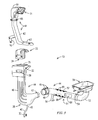
- FIG. 6 is a top perspective view showing a preferred configuration of the specially designed lower air box that replaces the stock lower air box and air inlet of a Jeep® Wrangler® brand vehicle.
- FIG. 1 shows a prior art factory air intake and air filter box of a Jeep® Wrangler® brand vehicle.
- a filter housing 11 comprises an upper cover 12 and a lower air box 13 that are secured together with spring clips 14 to enclose an interior portion that houses an air filter.
- the cover 12 communicates through an air conduit (not visible) with the throttle body of the engine.
- An air intake 17 has an opening between the air filter housing 11 and the fender 18 of the vehicle through which air is drawn by the engine.
- the air intake 17 communicates with the lower air box 13 of the filter housing 11 such that air drawn in through the air intake 17 enters the lower air box, passes through the internal filter within the housing 11 into the upper portion of the air box defined by the cover 12 , and the filtered air is drawn from the upper portion into the engine through the air conduit.
- the location of the factory air inlet in Jeep® Wrangler® brand and other brands of off-road vehicles is problematic for owners who engage in extreme off-road activities that may include fording streams and operating and dry dusty regions where clouds of dust are commonly kicked up around the vehicle.
- fording streams for example, the factory air inlet is located very near the front of the vehicle where water is pushed forward and aside as the vehicle moves through water. Water can thus rise or flow over the hood and become ingested through the air inlet 17 , increasing the chances of a hydrolock condition.
- the factory air inlet 17 is located such that it often is within the midst of dust clouds churned up by the vehicle during operation. Accordingly, much dust can easily be ingested, which can clog the air filter and threaten the engine. It will be appreciated that the factory air intake and filter box of such vehicles leaves much to be desired.
- FIG. 2 illustrates one embodiment of a modular snorkel assembly installed on a Jeep® Wrangler® brand vehicle according to aspects of the present invention.
- the vehicle 21 has a windshield 22 , a hood 23 , a fender 24 , and a forward cowl 26 . From the factory, there are two curved cowl pieces at the rear top of each fender 24 of the vehicle. According to aspects of the present invention, the curved cowl piece on the right side of the vehicle, which is the same side as the air filter box is on, is removed to accommodate the slightly protruding intake assembly 31 of the snorkel system described herein. More specifically, the intake mount 32 of the system projects from below through the opening left by removal of the right side cowl piece of the vehicle. The intake mount 32 is contoured such that it complements and fits neatly within the contours of the hood in front, the windshield frame in back, and the forward cowl to the side.
- the intake mount is formed with a mounting flange 35 ( FIG. 5 ) on its top surface and the mounting flange is configured to receive a variety of optional modules for configuring the snorkel system according to need and taste.
- the snorkel system is configured as a low intake system. More specifically, a low air intake module 33 is mounted to the intake mount 32 covering the mounting flange 35 and is secured to the intake mount 32 with bolts 36 and 37 .
- Bolts 36 are threaded downwardly into recessed nuts molded into the intake mount 32 to tighten the low intake module sealingly against the mounting flange 35 .
- bolts 37 also are threaded into recessed nuts in the intake mount 32 to secure the low intake module against the side of the intake mount and form a rugged rigid structure.
- a metal base plate 38 may be used to stabilize the bolts 37 and may double as a logo plate bearing the logo or trademark of a manufacturer or seller.
- the lower intake module 33 When secured to the intake mount 32 , the lower intake module 33 , in conjunction with the surfaces of the intake mount itself, define an air inlet 34 .
- the air inlet 34 faces downwardly and forces air 39 drawn through the inlet to travel a circuitous path first up through the air inlet, then around toward the mounting flange 35 in the top of the intake mount, then downwardly into the main body of the snorkel behind the finder 24 , as described in more detail below.
- the inventors have found through testing that such a configuration substantially eliminates water leakage through the air inlet 34 and into the main body of the snorkel system in prolonged and driving rains.
- the air inlet 34 is now located above the engine 3 feet behind and 7 inches above the location of the factory air inlet 17 ( FIG. 1 ).
- FIG. 3 shows the snorkel system of this invention installed on a Jeep® Wrangler® brand vehicle with the right fender of the vehicle removed to reveal the normally hidden remaining components of the snorkel system.
- the vehicle has a hood 23 , which is open in this figure to reveal the vehicle's engine 41 . With the outer fender removed, the inner fender 42 is visible as is the shock tower 43 and other frame components of the vehicle.
- the snorkel system 44 comprises a main body 46 having an intake mount formed at its upper end and terminating in a cylindrical outlet 47 .
- the outlet 47 is connected through a flexible coupling 48 and pipe clamps 49 to an end of a metal air tube 51 at the rear of the wheel well.
- the air tube 51 extends through the engine compartment between the exhaust manifold of the engine and the shock tower 43 to a forward end.
- a flexible elbow 53 attaches to the forward end of the air tube 51 and turns upwardly to connect to the lower air box 56 .
- the engine draws air through the low intake module as indicated at 39 , down through the main body 46 , through the air tube 51 and flexible elbow 53 and into the air box, where it passes through an air filter before moving to the throttle body of the engine.
- the main body 46 of the snorkel system extends first downwardly from its exposed intake mount 32 to a lower section 28 and thus defines a generally hollow downwardly extending air passageway that is relatively thin and wide.
- the thickness of the main body is selected so that the main body fits between the inner fender 42 and the outer fender 24 ( FIG. 2 ) and thus normally is hidden from view behind the outer fender.
- the width of this portion is selected such that the cross-sectional area throughout the passageway is at least the minimum cross-sectional air intake area required by the engine. In the case of the Jeep® Wrangler® brand vehicle shown, this minimum cross sectional area is about 6 square inches; however, other vehicles may have other requirements.
- the main body may be formed from any appropriate material through any appropriate fabrication technique, but in the illustrated embodiment is formed of a plastic material through a traditional blow molding process.
- the lower portion 28 of the main body 46 extends to a position that is significantly below the level of the cylindrical outlet 47 of the main body. In this way, the lower section 28 forms a sump within which any water splashed into or otherwise entering the intake of the snorkel assembly 44 is trapped and prevented from being drawn further through the snorkel and possibly into the engine of the vehicle.
- a nipple 45 is formed at the bottom of the main body for draining collected water from the sump and, in this embodiment; a drain tube 40 is coupled to the nipple 45 and terminates in a manual drain valve 30 .
- a user of the vehicle may open the drain valve 30 to allow any water collected in the sump to drain away. When not being used, the drain tube 40 may simply be tucked behind the outside fender and out of sight.
- the cylindrical outlet 47 of the main body which also has an internal cross sectional area of at least the minimum required by the engine, communicates with the rear end of the air tube 51 through a flexible connection 48 , which may, for example, comprise a rubber sleeve.
- the flexible connection 48 is fixed onto the cylindrical outlet 47 and onto the rear end of the air tube 51 by means of hose clamps 49 , which have been tightened around the flexible connection.
- the flexible connection 48 functions to, among other things, help absorb relative vibrations and other movements between the main body 46 and the air tube 51 of the snorkel system. This is important since the air tube is connected to the frame of the vehicle whereas the main body is connected to the body of the vehicle.
- the air tube 51 is made of an appropriate heat resistant material since it passes close to the normally hot exhaust manifold of the engine 41 .
- the air tube 51 is formed of metal, and more specifically of aluminum.
- a heat shield 55 ( FIG. 5 ) is welded or otherwise attached to the air tube 51 on the side of the tube that passes closest to the exhaust manifold and preferably defines an air space between the heat shield and the surface of the air tube 51 . This has been found to maintain the air tube 51 at a cool running temperature even though it passes within an inch or so of the exhaust manifold, which can reach temperatures of 600-700 degrees Fahrenheit.
- the forward end of the air tube 51 is coupled to a flexible elbow 53 and fastened thereto with a tightened hose clamp 54 .
- the elbow 53 extends forwardly from the forward end of the air tube 51 and thence turns upwardly beneath the air box of the vehicle.
- the snorkel system of the invention includes a modified lower air box wherein a cylindrical inlet projects downwardly from the bottom of the lower air box to be received into the upper end of the flexible elbow 53 .
- air can be drawn through the conduit formed by the snorkel system, into the lower air box, through the internal filter of the air box, and into the throttle body of the engine to be mixed with fuel.
- the flexible elbow helps to absorb any relative vibrations or motion between the air tube 51 and the air box, which are attached to different parts of the vehicle.
- FIG. 4 illustrates the modular snorkel system of this invention with a high intake module attached to the intake mount 32 of the main body.
- the intake mount 32 is formed with a rectangular coupling flange 35 that opens into the interior of the intake mount 32 .
- a low intake module 33 was described as being mounted to the intake mount covering the rectangular coupling flange 35 .
- the low intake module is removed and replaced by high intake module 61 that is secured to the intake mount 32 covering the coupling flange by bolts 64 .
- the high intake module 61 comprises a hollow mounting cowl 63 configured to fit sealingly over the coupling flange 35 so that the interior of the mounting cowl is in fluid communication with the main body of the system described above.
- a tubular extension 62 extends upwardly and slightly rearwardly from the rear end of the mounting cowl 63 and is configured to extend along a side of the windshield of the vehicle as shown.
- a bracket 76 secures the tubular extension 62 by being fastened to the vehicle body with bolts 77 , which may already be present on the vehicle.
- the tubular extension 62 terminates in a generally cylindrical open end 67 that preferably has a diameter that is standard in the industry for receiving various accessories such as in-line filters, ram intakes, and the like.
- a ram intake 68 is mounted on the cylindrical open end 67 and is removably secured with a hose clamp 65 .
- the ram intake 68 terminates in a generally forwardly facing inlet 71 through which air is drawn into the snorkel system and ultimately into the engine, as indicated by numeral 72 .
- the inlet 71 in this embodiment is spanned by a grille 63 , which prevents large insects and other debris from being ingested into the snorkel system.
- a logo plate 74 may be applied if desired for decorative effect and/or to display the logo of a company.
- a second logo plate 38 which is used as a support plate when the low intake module 33 is mounted as described above, is merely bolted to the side of the intake mount 32 to cover the mounting holes formed therethrough.
- FIG. 5 illustrates the modular snorkel system of this invention in exploded perspective and shows, perhaps better, many of the features of the various components of the system. Since the components have been described in detail above, they only need be described generally with respect to FIG. 5 .
- the system 10 comprises the main body 46 sized and configured to be hidden within the outer fender of a vehicle. It terminates at its upper end in intake mount 32 , which is formed with a rectangular mounting flange 35 .
- the main body 46 terminates at its other end in cylindrical outlet 47 and the lowermost portion of the main body defines a sump 28 below the level of the cylindrical outlet for trapping moisture.
- a nipple 45 communicates with the sump and is sized to receive a drain hose 40 having a drain valve 30 for draining water from the sump when necessary.
- the air tube 51 has a curved upstream end that is adapted to be coupled to the cylindrical end 47 of the main body with a flexible connector 48 and hose clamps 49 .
- a mounting stanchion 59 is welded or otherwise secured to the air tube 51 and extends downwardly therefrom in this embodiment for being secured with a bolt to the frame of the vehicle.
- a metal heat shield 52 is welded to the air tube at welds 89 and extends around the air tube on the hidden side in FIG. 5 at the location wherein the air tube is closest to the engines exhaust manifold.
- the heat shield 52 preferably is spaced from the surface of the air tube to define an air gap between the heat shield and the air tube.
- An indentation 88 may be formed in the air tube at the location where the air tube extends past the shock tower of the vehicle to avoid interference between the shock tower and the air tube 51 .
- a flexible elbow 53 is coupled to the forward end of the air tube 51 and curves upwardly where it is coupled at its other end to the cylindrical mounting flange 83 ( FIG. 6 ) of the lower air box 56 .
- the intake mount 32 is configured to accept one of a variety of intake modules as described.
- the low intake module 33 and the high intake module 61 are shown as options.
- the invention is not limited to these two modules, however, and a large number of other modules might well be incorporated such as pre-filters, domed intakes, and the like, all within the scope of the invention.
- FIG. 6 is a view from above of the lower air box of the snorkel system that replaces the factory lower air box of the air filter enclosure.
- the lower air box 56 which may be molded of plastic, includes an open top body having a floor with a circular opening 82 formed therethrough.
- a cylindrical mounting flange 83 extends downwardly from the opening 82 and is sized to receive the upper end of the flexible elbow 53 ( FIG. 5 ), which may be secured with a hose clamp or other fastener.
- the lower air box 56 is secured with bolts 81 , which preferable are sealed with sealant as shown.
- Clips 14 are applied to the modified lower air box of this system for locking the factory upper air box to the lower air box 56 with a filter element between them.
- air drawn through the snorkel system enters through the opening 82 in the lower air box, passes through the air filter into the upper air box, and moves into the engine through the throttle body.
- Other types of filter systems such as, for instance, in-line sealed filtration systems may be incorporated in place of the air filter arrangement shown in the preferred embodiments described herein, in which case the factory air box may be eliminated altogether.
- the air tube is illustrated as being made of aluminum in the preferred embodiments. It may, however, be made of another material such as molded plastic that is shaped and contoured to provide a sufficient clearance between the air tube and the hot engine.
- the particular route of the preferred embodiment through the engine bay and then behind the fender is not a limitation of the invention and other routs may be selected.
- the invention is directed to a snorkel system for off-road vehicles wherein the snorkel conduits are hidden from view except for the intake and wherein no irreversible modifications to the body of the vehicle are required for installation.
Landscapes
- Engineering & Computer Science (AREA)
- Chemical & Material Sciences (AREA)
- Combustion & Propulsion (AREA)
- Transportation (AREA)
- Mechanical Engineering (AREA)
- Cooling, Air Intake And Gas Exhaust, And Fuel Tank Arrangements In Propulsion Units (AREA)
Abstract
Description
Claims (14)
Priority Applications (1)
| Application Number | Priority Date | Filing Date | Title |
|---|---|---|---|
| US13/544,251 US8960347B2 (en) | 2012-07-09 | 2012-07-09 | Modular snorkel system for off-road vehicles |
Applications Claiming Priority (1)
| Application Number | Priority Date | Filing Date | Title |
|---|---|---|---|
| US13/544,251 US8960347B2 (en) | 2012-07-09 | 2012-07-09 | Modular snorkel system for off-road vehicles |
Publications (2)
| Publication Number | Publication Date |
|---|---|
| US20140008136A1 US20140008136A1 (en) | 2014-01-09 |
| US8960347B2 true US8960347B2 (en) | 2015-02-24 |
Family
ID=49877650
Family Applications (1)
| Application Number | Title | Priority Date | Filing Date |
|---|---|---|---|
| US13/544,251 Active 2033-02-22 US8960347B2 (en) | 2012-07-09 | 2012-07-09 | Modular snorkel system for off-road vehicles |
Country Status (1)
| Country | Link |
|---|---|
| US (1) | US8960347B2 (en) |
Cited By (29)
| Publication number | Priority date | Publication date | Assignee | Title |
|---|---|---|---|---|
| US9446796B2 (en) * | 2014-12-30 | 2016-09-20 | Kawasaki Jukogyo Kabushiki Kaisha | Utility vehicle |
| US20170130683A1 (en) * | 2015-11-10 | 2017-05-11 | Kenneth Somerville | Device and snorkel air intake comprising device |
| US9683527B2 (en) * | 2015-11-09 | 2017-06-20 | Kyle Tallman | Snorkel apparatus with auxiliary air tube supports |
| US10131222B1 (en) * | 2017-05-05 | 2018-11-20 | Toyota Motor Engineering & Manufacturing North America, Inc. | Snorkel roof drip attachment |
| US10337474B1 (en) | 2018-03-27 | 2019-07-02 | Honda Motor Co., Ltd. | Air intake system |
| USD856373S1 (en) * | 2015-11-09 | 2019-08-13 | Kyle Tallman | Octagonal snorkel |
| US10393076B1 (en) | 2018-08-30 | 2019-08-27 | Toyota Motor North America, Inc. | Tethered air intake snorkel |
| US10428773B1 (en) * | 2018-10-26 | 2019-10-01 | Omix-Ada, Inc. | Snorkel system |
| US10479194B1 (en) * | 2018-10-08 | 2019-11-19 | Honda Motor Co., Ltd. | Over fender air guide and snorkel protection |
| US10752106B1 (en) | 2019-04-30 | 2020-08-25 | Toyota Motor North America, Inc. | Snorkel slide-in attachment to vehicle body member |
| USD896277S1 (en) * | 2018-10-25 | 2020-09-15 | Omix-Ada, Inc. | High-mount snorkel |
| USD896142S1 (en) | 2018-10-23 | 2020-09-15 | Omix-Ada, Inc. | Low mount snorkel |
| USD905117S1 (en) | 2018-10-23 | 2020-12-15 | Omix-Ada, Inc. | Intake ram |
| US10946736B2 (en) | 2018-06-05 | 2021-03-16 | Polaris Industries Inc. | All-terrain vehicle |
| USD927555S1 (en) * | 2020-03-17 | 2021-08-10 | Omix-Ada, Inc. | Snorkel system |
| US11181083B2 (en) | 2019-12-19 | 2021-11-23 | Nissan North America, Inc. | Snorkel installation kit |
| US11203261B2 (en) | 2019-12-10 | 2021-12-21 | Ford Global Technologies, Llc | Systems and methods for controlling air induction to an engine of a vehicle |
| USD943634S1 (en) | 2020-03-26 | 2022-02-15 | Omix-Ada, Inc. | Snorkel system |
| WO2021163711A3 (en) * | 2020-02-09 | 2022-02-17 | Velossa Tech Engineering Inc. | Interchangeable intake manifold assemblies with interchangeable flare housings |
| US11752860B2 (en) | 2015-05-15 | 2023-09-12 | Polaris Industries Inc. | Utility vehicle |
| US20230356127A1 (en) * | 2012-11-01 | 2023-11-09 | Advanced Flow Engineering Inc. | Air Intake Assembly and Methods Thereof |
| USD1019704S1 (en) | 2020-02-09 | 2024-03-26 | Velossa Tech Engineering, Inc. | Ram-air intake |
| US11952971B2 (en) | 2021-12-06 | 2024-04-09 | Ford Global Technologies, Llc | Methods and system for evaluating an engine for hydrolock |
| USD1023061S1 (en) | 2020-02-09 | 2024-04-16 | Velossa Tech Engineering, Inc. | Ram-air intake |
| USD1031782S1 (en) | 2020-02-09 | 2024-06-18 | Velossa Tech Engineering, Inc. | Ram-air intake |
| USD1044872S1 (en) | 2021-12-06 | 2024-10-01 | Danny E. Siems | Air intake tubing for utility terrain vehicle |
| US12337690B2 (en) | 2020-05-15 | 2025-06-24 | Polaris Industries Inc. | Off-road vehicle |
| US12385429B2 (en) | 2022-06-13 | 2025-08-12 | Polaris Industries Inc. | Powertrain for a utility vehicle |
| USD1103845S1 (en) | 2023-01-20 | 2025-12-02 | Polaris Industries Inc. | Grille for an off-road vehicle |
Families Citing this family (30)
| Publication number | Priority date | Publication date | Assignee | Title |
|---|---|---|---|---|
| US20140360794A1 (en) * | 2013-06-10 | 2014-12-11 | Kyle Tallman | Snorkel Apparatus and Method of Use for All-Terrain Vehicles |
| USD752109S1 (en) * | 2014-07-09 | 2016-03-22 | Streetcar ORV LLC | Snorkel |
| US20160030233A1 (en) * | 2014-08-01 | 2016-02-04 | Empire Technology Development Llc | Apparatuses and methods for cooling a surface |
| USD774101S1 (en) * | 2015-04-13 | 2016-12-13 | Ron Delgado | Snorkel |
| JP6627110B2 (en) * | 2015-07-03 | 2020-01-08 | トヨタ車体株式会社 | Vehicle snorkel |
| US9884647B2 (en) | 2015-12-10 | 2018-02-06 | Polaris Industries Inc. | Utility vehicle |
| USD792470S1 (en) * | 2016-04-22 | 2017-07-18 | Centrifugal Universal Filtration Technology (Pty) Ltd | Vehicle snorkel |
| USD788175S1 (en) * | 2016-04-22 | 2017-05-30 | Centrifugal Universal Filtration Technology (Pty) Ltd | Front cover for vehicle snorkel |
| USD805106S1 (en) * | 2016-04-22 | 2017-12-12 | Centrifugal Universal Filtration Technology (Pty) Ltd | Pre-cleaner insert for vehicle snorkel |
| USD787559S1 (en) * | 2016-04-22 | 2017-05-23 | Centrifugal Universal Filtration Technology (Pty) Ltd | Filter housing for vehicle snorkel |
| US11173808B2 (en) | 2016-12-22 | 2021-11-16 | Polaris Industies Inc. | Vehicle |
| DE112017006254T5 (en) * | 2017-01-10 | 2019-09-12 | Ford Global Technologies, Llc | VEHICLE ENTRY-DISTRIBUTION SYSTEM |
| AU201811306S (en) * | 2018-03-06 | 2018-03-28 | Safari R&D Pty Ltd | Air intake snorkel for a vehicle |
| US20190283674A1 (en) * | 2018-03-16 | 2019-09-19 | Omix-Ada | Quick release mirror mount |
| USD883331S1 (en) * | 2019-03-24 | 2020-05-05 | Safari R&D Pty Ltd | Air intake snorkel for a vehicle |
| US11628722B2 (en) | 2019-04-30 | 2023-04-18 | Polaris Industries Inc. | Vehicle |
| USD896844S1 (en) * | 2019-05-20 | 2020-09-22 | Safari R&D Pty Ltd | Air intake snorkel for a vehicle |
| USD882637S1 (en) * | 2019-07-24 | 2020-04-28 | Safari R&D Pty Ltd | Air intake snorkel for a vehicle |
| US11242828B2 (en) | 2019-11-15 | 2022-02-08 | Reinhold E. Kober | Snow bike intake |
| USD947081S1 (en) * | 2020-01-02 | 2022-03-29 | Bravo Deal, S.L. | Air-intake grille for vehicles |
| USD947080S1 (en) * | 2020-01-02 | 2022-03-29 | Bravo Deal, S.L. | Air-intake grille for vehicles |
| US11691674B2 (en) | 2020-05-15 | 2023-07-04 | Polaris Industries Inc. | Off-road vehicle |
| USD967861S1 (en) * | 2020-10-23 | 2022-10-25 | Bravo Deal, S.L. | Air filter for vehicles |
| US20220135005A1 (en) * | 2020-10-29 | 2022-05-05 | Argo AI, LLC | Method and system for diverting ram air to vehicle sensors |
| USD963699S1 (en) * | 2021-03-31 | 2022-09-13 | Bravo Deal, S.L. | Air filter for vehicles |
| USD969170S1 (en) * | 2021-03-31 | 2022-11-08 | Bravo Deal, S.L. | Air filter for vehicles |
| CN115366995A (en) * | 2021-05-21 | 2022-11-22 | 广东东箭汽车科技股份有限公司 | Ventilation radiator and car of engine bonnet |
| USD971262S1 (en) * | 2022-02-11 | 2022-11-29 | Resource Intl Inc. | Snorkel for automotive applications |
| USD1103885S1 (en) | 2022-02-11 | 2025-12-02 | Resource Intl Inc. | Snorkel head assembly |
| US12203431B2 (en) * | 2022-06-15 | 2025-01-21 | Bombardier Recreational Products Inc. | Off-road vehicle air intake system and windshield |
Citations (14)
| Publication number | Priority date | Publication date | Assignee | Title |
|---|---|---|---|---|
| US5671802A (en) * | 1995-10-05 | 1997-09-30 | General Motors Corporation | Electronic control module cooling device |
| US6152096A (en) * | 1999-07-06 | 2000-11-28 | Visteon Global Technologies, Inc. | Storage battery protection by engine air intake system |
| US6287354B1 (en) * | 1998-12-18 | 2001-09-11 | Honda Giken Kogyo Kabushiki Kaisha | Vehicular air cleaner device |
| US6314931B1 (en) * | 1999-09-05 | 2001-11-13 | Honda Giken Kogyo Kabushiki Kaisha | Structure of snorkel duct for rough ground running vehicle |
| US20020023792A1 (en) * | 2000-08-31 | 2002-02-28 | Bombardier Inc. | Air intake for a straddle-type all terrain vehicle |
| US6530443B1 (en) * | 1999-09-03 | 2003-03-11 | Honda Giken Kogyo Kabushiki Kaisha | Structure of attaching heat insulator |
| US20050217625A1 (en) * | 2004-04-05 | 2005-10-06 | Advanced Flow Engineering, Inc. | Heat shielded air intake system |
| US20060065231A1 (en) * | 2004-09-29 | 2006-03-30 | Honda Motor Co., Ltd. | Air cleaner device in vehicle |
| US20060219209A1 (en) * | 2005-03-31 | 2006-10-05 | Honda Motor Co., Ltd. | Saddle-ride type vehicle |
| US20060230728A1 (en) * | 2005-03-31 | 2006-10-19 | Honda Motor Co., Ltd. | Structure of air cleaner box |
| US20070012274A1 (en) * | 2005-06-23 | 2007-01-18 | Honda Motor Co., Ltd. | Air cleaner in all terrain vehicle |
| US20090260906A1 (en) * | 2008-04-17 | 2009-10-22 | Derk Hartland | Automotive Vehicle Engine Apparatus |
| US20100078239A1 (en) * | 2008-09-30 | 2010-04-01 | Kevin Christopher Beloy | Vehicles and methods of controlling intake airflow |
| US20100083928A1 (en) * | 2007-01-29 | 2010-04-08 | Toyota Jidosha Kabushiki Kaisha | Intake system for vehicle internal combustion engine |
-
2012
- 2012-07-09 US US13/544,251 patent/US8960347B2/en active Active
Patent Citations (14)
| Publication number | Priority date | Publication date | Assignee | Title |
|---|---|---|---|---|
| US5671802A (en) * | 1995-10-05 | 1997-09-30 | General Motors Corporation | Electronic control module cooling device |
| US6287354B1 (en) * | 1998-12-18 | 2001-09-11 | Honda Giken Kogyo Kabushiki Kaisha | Vehicular air cleaner device |
| US6152096A (en) * | 1999-07-06 | 2000-11-28 | Visteon Global Technologies, Inc. | Storage battery protection by engine air intake system |
| US6530443B1 (en) * | 1999-09-03 | 2003-03-11 | Honda Giken Kogyo Kabushiki Kaisha | Structure of attaching heat insulator |
| US6314931B1 (en) * | 1999-09-05 | 2001-11-13 | Honda Giken Kogyo Kabushiki Kaisha | Structure of snorkel duct for rough ground running vehicle |
| US20020023792A1 (en) * | 2000-08-31 | 2002-02-28 | Bombardier Inc. | Air intake for a straddle-type all terrain vehicle |
| US20050217625A1 (en) * | 2004-04-05 | 2005-10-06 | Advanced Flow Engineering, Inc. | Heat shielded air intake system |
| US20060065231A1 (en) * | 2004-09-29 | 2006-03-30 | Honda Motor Co., Ltd. | Air cleaner device in vehicle |
| US20060219209A1 (en) * | 2005-03-31 | 2006-10-05 | Honda Motor Co., Ltd. | Saddle-ride type vehicle |
| US20060230728A1 (en) * | 2005-03-31 | 2006-10-19 | Honda Motor Co., Ltd. | Structure of air cleaner box |
| US20070012274A1 (en) * | 2005-06-23 | 2007-01-18 | Honda Motor Co., Ltd. | Air cleaner in all terrain vehicle |
| US20100083928A1 (en) * | 2007-01-29 | 2010-04-08 | Toyota Jidosha Kabushiki Kaisha | Intake system for vehicle internal combustion engine |
| US20090260906A1 (en) * | 2008-04-17 | 2009-10-22 | Derk Hartland | Automotive Vehicle Engine Apparatus |
| US20100078239A1 (en) * | 2008-09-30 | 2010-04-01 | Kevin Christopher Beloy | Vehicles and methods of controlling intake airflow |
Cited By (40)
| Publication number | Priority date | Publication date | Assignee | Title |
|---|---|---|---|---|
| US20230356127A1 (en) * | 2012-11-01 | 2023-11-09 | Advanced Flow Engineering Inc. | Air Intake Assembly and Methods Thereof |
| US9446796B2 (en) * | 2014-12-30 | 2016-09-20 | Kawasaki Jukogyo Kabushiki Kaisha | Utility vehicle |
| US12552246B2 (en) | 2015-05-15 | 2026-02-17 | Polaris Industries Inc. | Utility vehicle |
| US11752860B2 (en) | 2015-05-15 | 2023-09-12 | Polaris Industries Inc. | Utility vehicle |
| USD856373S1 (en) * | 2015-11-09 | 2019-08-13 | Kyle Tallman | Octagonal snorkel |
| US9683527B2 (en) * | 2015-11-09 | 2017-06-20 | Kyle Tallman | Snorkel apparatus with auxiliary air tube supports |
| US10060395B2 (en) * | 2015-11-10 | 2018-08-28 | Kenneth Somerville | Device and snorkel air intake comprising device |
| US20170130683A1 (en) * | 2015-11-10 | 2017-05-11 | Kenneth Somerville | Device and snorkel air intake comprising device |
| US10131222B1 (en) * | 2017-05-05 | 2018-11-20 | Toyota Motor Engineering & Manufacturing North America, Inc. | Snorkel roof drip attachment |
| US10337474B1 (en) | 2018-03-27 | 2019-07-02 | Honda Motor Co., Ltd. | Air intake system |
| US10946736B2 (en) | 2018-06-05 | 2021-03-16 | Polaris Industries Inc. | All-terrain vehicle |
| US10393076B1 (en) | 2018-08-30 | 2019-08-27 | Toyota Motor North America, Inc. | Tethered air intake snorkel |
| US10479194B1 (en) * | 2018-10-08 | 2019-11-19 | Honda Motor Co., Ltd. | Over fender air guide and snorkel protection |
| USD905117S1 (en) | 2018-10-23 | 2020-12-15 | Omix-Ada, Inc. | Intake ram |
| USD896142S1 (en) | 2018-10-23 | 2020-09-15 | Omix-Ada, Inc. | Low mount snorkel |
| USD896277S1 (en) * | 2018-10-25 | 2020-09-15 | Omix-Ada, Inc. | High-mount snorkel |
| DE102019122504B4 (en) | 2018-10-26 | 2023-08-31 | Omix-Ada, Inc. | snorkel system |
| US10711744B2 (en) * | 2018-10-26 | 2020-07-14 | Omix-Ada, Inc. | Snorkel system |
| DE102019122504A1 (en) | 2018-10-26 | 2020-04-30 | Omix-Ada, Inc. | Snorkeling system |
| US10428773B1 (en) * | 2018-10-26 | 2019-10-01 | Omix-Ada, Inc. | Snorkel system |
| US10752106B1 (en) | 2019-04-30 | 2020-08-25 | Toyota Motor North America, Inc. | Snorkel slide-in attachment to vehicle body member |
| US11203261B2 (en) | 2019-12-10 | 2021-12-21 | Ford Global Technologies, Llc | Systems and methods for controlling air induction to an engine of a vehicle |
| US11181083B2 (en) | 2019-12-19 | 2021-11-23 | Nissan North America, Inc. | Snorkel installation kit |
| USD1023061S1 (en) | 2020-02-09 | 2024-04-16 | Velossa Tech Engineering, Inc. | Ram-air intake |
| US12516649B2 (en) | 2020-02-09 | 2026-01-06 | Velossa Tech Engineering Inc. | Interchangeable intake manifold assemblies with interchangeable flare housings |
| WO2021163711A3 (en) * | 2020-02-09 | 2022-02-17 | Velossa Tech Engineering Inc. | Interchangeable intake manifold assemblies with interchangeable flare housings |
| USD1007531S1 (en) | 2020-02-09 | 2023-12-12 | Velossa Tech Engineering, Inc. | Ram-air intake |
| USD1007532S1 (en) | 2020-02-09 | 2023-12-12 | Velossa Tech Engineering, Inc. | Ram-air intake |
| USD1019704S1 (en) | 2020-02-09 | 2024-03-26 | Velossa Tech Engineering, Inc. | Ram-air intake |
| USD1031782S1 (en) | 2020-02-09 | 2024-06-18 | Velossa Tech Engineering, Inc. | Ram-air intake |
| GB2607248A (en) * | 2020-02-09 | 2022-11-30 | Velossa Tech Eng Inc | Interchangeable intake manifold assemblies with interchangeable flare housings |
| GB2607248B (en) * | 2020-02-09 | 2024-10-02 | Velossa Tech Eng | Interchangeable intake manifold assemblies with interchangeable flare housings |
| US12180916B2 (en) | 2020-02-09 | 2024-12-31 | Velossa Tech Engineering Inc. | Interchangeable intake manifold assemblies |
| USD927555S1 (en) * | 2020-03-17 | 2021-08-10 | Omix-Ada, Inc. | Snorkel system |
| USD943634S1 (en) | 2020-03-26 | 2022-02-15 | Omix-Ada, Inc. | Snorkel system |
| US12337690B2 (en) | 2020-05-15 | 2025-06-24 | Polaris Industries Inc. | Off-road vehicle |
| USD1044872S1 (en) | 2021-12-06 | 2024-10-01 | Danny E. Siems | Air intake tubing for utility terrain vehicle |
| US11952971B2 (en) | 2021-12-06 | 2024-04-09 | Ford Global Technologies, Llc | Methods and system for evaluating an engine for hydrolock |
| US12385429B2 (en) | 2022-06-13 | 2025-08-12 | Polaris Industries Inc. | Powertrain for a utility vehicle |
| USD1103845S1 (en) | 2023-01-20 | 2025-12-02 | Polaris Industries Inc. | Grille for an off-road vehicle |
Also Published As
| Publication number | Publication date |
|---|---|
| US20140008136A1 (en) | 2014-01-09 |
Similar Documents
| Publication | Publication Date | Title |
|---|---|---|
| US8960347B2 (en) | Modular snorkel system for off-road vehicles | |
| US11181083B2 (en) | Snorkel installation kit | |
| US10393076B1 (en) | Tethered air intake snorkel | |
| US9062639B1 (en) | Dual inlet air induction system with panel filter for vehicle engine | |
| US8434580B2 (en) | Utility vehicle with air-intake apparatus for engine | |
| CA3166727C (en) | All-terrain vehicle | |
| US8316975B2 (en) | Four wheeled vehicle with air-intake apparatus for engine | |
| US20050217625A1 (en) | Heat shielded air intake system | |
| US10060395B2 (en) | Device and snorkel air intake comprising device | |
| US7571714B2 (en) | Relative configuration of an engine intake pipe for a motorcycle | |
| US5199522A (en) | Air inlet for vehicle engine | |
| US9410512B2 (en) | Air intake apparatus for four wheeled utility vehicle | |
| US7278504B2 (en) | Integrated fan shroud air intake system | |
| US8919480B2 (en) | Motorcycle | |
| US10724482B2 (en) | Air cleaner connecting tube structure | |
| US10711737B2 (en) | Conduit mounting device | |
| WO2016126187A1 (en) | Air intake | |
| US7690461B2 (en) | All terrain vehicle | |
| WO2013095881A1 (en) | Air supply system for a vehicle | |
| JPH06135246A (en) | Auxiliary machine arrangement method into engine room and auxiliary machine arrangement structure | |
| JPS6035122Y2 (en) | Headlamp device for internal combustion engine mounted on agricultural machinery | |
| US8789633B2 (en) | Vehicle including intake assembly having snorkel | |
| US8835759B1 (en) | Support containers and vehicles including same | |
| CN108869115B (en) | Air cleaner unit and engine with air cleaner unit | |
| US20260048653A1 (en) | Modular hood plenum |
Legal Events
| Date | Code | Title | Description |
|---|---|---|---|
| AS | Assignment |
Owner name: OMIX-ADA, INC., GEORGIA Free format text: ASSIGNMENT OF ASSIGNORS INTEREST;ASSIGNOR:BENNETT, PATRICK W.;REEL/FRAME:028851/0480 Effective date: 20120808 |
|
| STCF | Information on status: patent grant |
Free format text: PATENTED CASE |
|
| AS | Assignment |
Owner name: JEFFERIES FINANCE LLC, AS ADMINISTRATIVE AND COLLA Free format text: PATENT SECURITY AGREEMENT (FIRST LIEN);ASSIGNOR:OMIX-ADA, INC.;REEL/FRAME:044947/0542 Effective date: 20171211 |
|
| AS | Assignment |
Owner name: JEFFERIES FINANCE LLC, AS ADMINISTRATIVE AND COLLA Free format text: PATENT SECURITY AGREEMENT (SECOND LIEN);ASSIGNOR:OMIX-ADA, INC.;REEL/FRAME:044967/0572 Effective date: 20171211 |
|
| FEPP | Fee payment procedure |
Free format text: ENTITY STATUS SET TO UNDISCOUNTED (ORIGINAL EVENT CODE: BIG.); ENTITY STATUS OF PATENT OWNER: LARGE ENTITY |
|
| MAFP | Maintenance fee payment |
Free format text: PAYMENT OF MAINTENANCE FEE, 4TH YEAR, LARGE ENTITY (ORIGINAL EVENT CODE: M1551); ENTITY STATUS OF PATENT OWNER: LARGE ENTITY Year of fee payment: 4 |
|
| AS | Assignment |
Owner name: WILMINGTON TRUST, NATIONAL ASSOCIATION, AS COLLATE Free format text: PATENT SECURITY AGREEMENT (INDENTURE);ASSIGNOR:OMIX-ADA, INC.;REEL/FRAME:049677/0724 Effective date: 20190510 Owner name: WILMINGTON TRUST, NATIONAL ASSOCIATION, AS COLLATERAL AGENT, MINNESOTA Free format text: PATENT SECURITY AGREEMENT (INDENTURE);ASSIGNOR:OMIX-ADA, INC.;REEL/FRAME:049677/0724 Effective date: 20190510 |
|
| AS | Assignment |
Owner name: JEFFERIES FINANCE LLC, AS COLLATERAL AGENT, NEW YORK Free format text: PATENT SECURITY AGREEMENT (TL);ASSIGNOR:OMIX-ADA, INC.;REEL/FRAME:055175/0153 Effective date: 20210129 Owner name: BANK OF AMERICA, N.A., AS COLLATERAL AGENT, TEXAS Free format text: PATENT SECURITY AGREEMENT (ABL);ASSIGNOR:OMIX-ADA, INC.;REEL/FRAME:055176/0336 Effective date: 20210129 |
|
| AS | Assignment |
Owner name: OMIX-ADA, INC., GEORGIA Free format text: RELEASE OF FIRST LIEN SECURITY INTEREST IN PATENTS;ASSIGNOR:JEFFERIES FINANCE LLC, AS ADMINISTRATIVE AND COLLATERAL AGENT;REEL/FRAME:055189/0224 Effective date: 20210129 Owner name: OMIX-ADA, INC., GEORGIA Free format text: RELEASE OF SECOND LIEN SECURITY INTEREST IN PATENTS;ASSIGNOR:JEFFERIES FINANCE LLC, AS ADMINISTRATIVE AND COLLATERAL AGENT;REEL/FRAME:055189/0214 Effective date: 20210129 |
|
| AS | Assignment |
Owner name: UNDERCOVER, INC., MISSOURI Free format text: RELEASE BY SECURED PARTY;ASSIGNOR:WILMINGTON TRUST, NATIONAL ASSOCIATION, AS COLLATERAL AGENT;REEL/FRAME:055193/0892 Effective date: 20210129 Owner name: EXTANG CORPORATION, MICHIGAN Free format text: RELEASE BY SECURED PARTY;ASSIGNOR:WILMINGTON TRUST, NATIONAL ASSOCIATION, AS COLLATERAL AGENT;REEL/FRAME:055193/0892 Effective date: 20210129 Owner name: LAURMARK ENTERPRISES, INC., MICHIGAN Free format text: RELEASE BY SECURED PARTY;ASSIGNOR:WILMINGTON TRUST, NATIONAL ASSOCIATION, AS COLLATERAL AGENT;REEL/FRAME:055193/0892 Effective date: 20210129 Owner name: N-FAB, INC., TEXAS Free format text: RELEASE BY SECURED PARTY;ASSIGNOR:WILMINGTON TRUST, NATIONAL ASSOCIATION, AS COLLATERAL AGENT;REEL/FRAME:055193/0892 Effective date: 20210129 Owner name: ADVANTAGE TRUCK ACCESSORIES INC., MICHIGAN Free format text: RELEASE BY SECURED PARTY;ASSIGNOR:WILMINGTON TRUST, NATIONAL ASSOCIATION, AS COLLATERAL AGENT;REEL/FRAME:055193/0892 Effective date: 20210129 Owner name: OMIX-ADA, INC., GEORGIA Free format text: RELEASE BY SECURED PARTY;ASSIGNOR:WILMINGTON TRUST, NATIONAL ASSOCIATION, AS COLLATERAL AGENT;REEL/FRAME:055193/0892 Effective date: 20210129 Owner name: HUSKY LINERS, INC., KANSAS Free format text: RELEASE BY SECURED PARTY;ASSIGNOR:WILMINGTON TRUST, NATIONAL ASSOCIATION, AS COLLATERAL AGENT;REEL/FRAME:055193/0892 Effective date: 20210129 Owner name: RUGGED LINER, INC., MICHIGAN Free format text: RELEASE BY SECURED PARTY;ASSIGNOR:WILMINGTON TRUST, NATIONAL ASSOCIATION, AS COLLATERAL AGENT;REEL/FRAME:055193/0892 Effective date: 20210129 Owner name: LUND MOTION PRODUCTS, INC., GEORGIA Free format text: RELEASE BY SECURED PARTY;ASSIGNOR:WILMINGTON TRUST, NATIONAL ASSOCIATION, AS COLLATERAL AGENT;REEL/FRAME:055193/0892 Effective date: 20210129 Owner name: BUSHWACKER, INC., GEORGIA Free format text: RELEASE BY SECURED PARTY;ASSIGNOR:WILMINGTON TRUST, NATIONAL ASSOCIATION, AS COLLATERAL AGENT;REEL/FRAME:055193/0892 Effective date: 20210129 Owner name: A.R.E. ACCESSORIES LLC, OHIO Free format text: RELEASE BY SECURED PARTY;ASSIGNOR:WILMINGTON TRUST, NATIONAL ASSOCIATION, AS COLLATERAL AGENT;REEL/FRAME:055193/0892 Effective date: 20210129 Owner name: TRUXEDO INC., SOUTH DAKOTA Free format text: RELEASE BY SECURED PARTY;ASSIGNOR:WILMINGTON TRUST, NATIONAL ASSOCIATION, AS COLLATERAL AGENT;REEL/FRAME:055193/0892 Effective date: 20210129 Owner name: ROLL-N-LOCK CORPORATION, GEORGIA Free format text: RELEASE BY SECURED PARTY;ASSIGNOR:WILMINGTON TRUST, NATIONAL ASSOCIATION, AS COLLATERAL AGENT;REEL/FRAME:055193/0892 Effective date: 20210129 Owner name: LUND, INC., GEORGIA Free format text: RELEASE BY SECURED PARTY;ASSIGNOR:WILMINGTON TRUST, NATIONAL ASSOCIATION, AS COLLATERAL AGENT;REEL/FRAME:055193/0892 Effective date: 20210129 Owner name: RETRAX HOLDINGS, LLC, NORTH DAKOTA Free format text: RELEASE BY SECURED PARTY;ASSIGNOR:WILMINGTON TRUST, NATIONAL ASSOCIATION, AS COLLATERAL AGENT;REEL/FRAME:055193/0892 Effective date: 20210129 Owner name: BEDRUG, INC., TENNESSEE Free format text: RELEASE BY SECURED PARTY;ASSIGNOR:WILMINGTON TRUST, NATIONAL ASSOCIATION, AS COLLATERAL AGENT;REEL/FRAME:055193/0892 Effective date: 20210129 Owner name: EXTANG CORPORATION, MICHIGAN Free format text: RELEASE OF SECURITY INTEREST;ASSIGNOR:WILMINGTON TRUST, NATIONAL ASSOCIATION, AS COLLATERAL AGENT;REEL/FRAME:055193/0892 Effective date: 20210129 Owner name: TRUXEDO INC., SOUTH DAKOTA Free format text: RELEASE OF SECURITY INTEREST;ASSIGNOR:WILMINGTON TRUST, NATIONAL ASSOCIATION, AS COLLATERAL AGENT;REEL/FRAME:055193/0892 Effective date: 20210129 Owner name: BEDRUG, INC., TENNESSEE Free format text: RELEASE OF SECURITY INTEREST;ASSIGNOR:WILMINGTON TRUST, NATIONAL ASSOCIATION, AS COLLATERAL AGENT;REEL/FRAME:055193/0892 Effective date: 20210129 Owner name: UNDERCOVER, INC., MISSOURI Free format text: RELEASE OF SECURITY INTEREST;ASSIGNOR:WILMINGTON TRUST, NATIONAL ASSOCIATION, AS COLLATERAL AGENT;REEL/FRAME:055193/0892 Effective date: 20210129 Owner name: RETRAX HOLDINGS, LLC, NORTH DAKOTA Free format text: RELEASE OF SECURITY INTEREST;ASSIGNOR:WILMINGTON TRUST, NATIONAL ASSOCIATION, AS COLLATERAL AGENT;REEL/FRAME:055193/0892 Effective date: 20210129 Owner name: ADVANTAGE TRUCK ACCESSORIES INC., MICHIGAN Free format text: RELEASE OF SECURITY INTEREST;ASSIGNOR:WILMINGTON TRUST, NATIONAL ASSOCIATION, AS COLLATERAL AGENT;REEL/FRAME:055193/0892 Effective date: 20210129 Owner name: LAURMARK ENTERPRISES, INC., MICHIGAN Free format text: RELEASE OF SECURITY INTEREST;ASSIGNOR:WILMINGTON TRUST, NATIONAL ASSOCIATION, AS COLLATERAL AGENT;REEL/FRAME:055193/0892 Effective date: 20210129 Owner name: A.R.E. ACCESSORIES LLC, OHIO Free format text: RELEASE OF SECURITY INTEREST;ASSIGNOR:WILMINGTON TRUST, NATIONAL ASSOCIATION, AS COLLATERAL AGENT;REEL/FRAME:055193/0892 Effective date: 20210129 Owner name: N-FAB, INC., TEXAS Free format text: RELEASE OF SECURITY INTEREST;ASSIGNOR:WILMINGTON TRUST, NATIONAL ASSOCIATION, AS COLLATERAL AGENT;REEL/FRAME:055193/0892 Effective date: 20210129 Owner name: RUGGED LINER, INC., MICHIGAN Free format text: RELEASE OF SECURITY INTEREST;ASSIGNOR:WILMINGTON TRUST, NATIONAL ASSOCIATION, AS COLLATERAL AGENT;REEL/FRAME:055193/0892 Effective date: 20210129 Owner name: HUSKY LINERS, INC., KANSAS Free format text: RELEASE OF SECURITY INTEREST;ASSIGNOR:WILMINGTON TRUST, NATIONAL ASSOCIATION, AS COLLATERAL AGENT;REEL/FRAME:055193/0892 Effective date: 20210129 Owner name: OMIX-ADA, INC., GEORGIA Free format text: RELEASE OF SECURITY INTEREST;ASSIGNOR:WILMINGTON TRUST, NATIONAL ASSOCIATION, AS COLLATERAL AGENT;REEL/FRAME:055193/0892 Effective date: 20210129 Owner name: LUND, INC., GEORGIA Free format text: RELEASE OF SECURITY INTEREST;ASSIGNOR:WILMINGTON TRUST, NATIONAL ASSOCIATION, AS COLLATERAL AGENT;REEL/FRAME:055193/0892 Effective date: 20210129 Owner name: ROLL-N-LOCK CORPORATION, GEORGIA Free format text: RELEASE OF SECURITY INTEREST;ASSIGNOR:WILMINGTON TRUST, NATIONAL ASSOCIATION, AS COLLATERAL AGENT;REEL/FRAME:055193/0892 Effective date: 20210129 Owner name: LUND MOTION PRODUCTS, INC., GEORGIA Free format text: RELEASE OF SECURITY INTEREST;ASSIGNOR:WILMINGTON TRUST, NATIONAL ASSOCIATION, AS COLLATERAL AGENT;REEL/FRAME:055193/0892 Effective date: 20210129 Owner name: BUSHWACKER, INC., GEORGIA Free format text: RELEASE OF SECURITY INTEREST;ASSIGNOR:WILMINGTON TRUST, NATIONAL ASSOCIATION, AS COLLATERAL AGENT;REEL/FRAME:055193/0892 Effective date: 20210129 |
|
| MAFP | Maintenance fee payment |
Free format text: PAYMENT OF MAINTENANCE FEE, 8TH YEAR, LARGE ENTITY (ORIGINAL EVENT CODE: M1552); ENTITY STATUS OF PATENT OWNER: LARGE ENTITY Year of fee payment: 8 |